EP2518275A2 - Moisture monitoring system for gas turbine engines - Google Patents
Moisture monitoring system for gas turbine engines Download PDFInfo
- Publication number
- EP2518275A2 EP2518275A2 EP12166078A EP12166078A EP2518275A2 EP 2518275 A2 EP2518275 A2 EP 2518275A2 EP 12166078 A EP12166078 A EP 12166078A EP 12166078 A EP12166078 A EP 12166078A EP 2518275 A2 EP2518275 A2 EP 2518275A2
- Authority
- EP
- European Patent Office
- Prior art keywords
- moisture
- recited
- composite material
- control
- sensor system
- Prior art date
- Legal status (The legal status is an assumption and is not a legal conclusion. Google has not performed a legal analysis and makes no representation as to the accuracy of the status listed.)
- Granted
Links
Images

Classifications
-
- F—MECHANICAL ENGINEERING; LIGHTING; HEATING; WEAPONS; BLASTING
- F01—MACHINES OR ENGINES IN GENERAL; ENGINE PLANTS IN GENERAL; STEAM ENGINES
- F01D—NON-POSITIVE DISPLACEMENT MACHINES OR ENGINES, e.g. STEAM TURBINES
- F01D17/00—Regulating or controlling by varying flow
- F01D17/02—Arrangement of sensing elements
-
- F—MECHANICAL ENGINEERING; LIGHTING; HEATING; WEAPONS; BLASTING
- F01—MACHINES OR ENGINES IN GENERAL; ENGINE PLANTS IN GENERAL; STEAM ENGINES
- F01D—NON-POSITIVE DISPLACEMENT MACHINES OR ENGINES, e.g. STEAM TURBINES
- F01D21/00—Shutting-down of machines or engines, e.g. in emergency; Regulating, controlling, or safety means not otherwise provided for
- F01D21/14—Shutting-down of machines or engines, e.g. in emergency; Regulating, controlling, or safety means not otherwise provided for responsive to other specific conditions
-
- G—PHYSICS
- G01—MEASURING; TESTING
- G01N—INVESTIGATING OR ANALYSING MATERIALS BY DETERMINING THEIR CHEMICAL OR PHYSICAL PROPERTIES
- G01N27/00—Investigating or analysing materials by the use of electric, electrochemical, or magnetic means
- G01N27/02—Investigating or analysing materials by the use of electric, electrochemical, or magnetic means by investigating impedance
- G01N27/04—Investigating or analysing materials by the use of electric, electrochemical, or magnetic means by investigating impedance by investigating resistance
- G01N27/12—Investigating or analysing materials by the use of electric, electrochemical, or magnetic means by investigating impedance by investigating resistance of a solid body in dependence upon absorption of a fluid; of a solid body in dependence upon reaction with a fluid, for detecting components in the fluid
- G01N27/121—Investigating or analysing materials by the use of electric, electrochemical, or magnetic means by investigating impedance by investigating resistance of a solid body in dependence upon absorption of a fluid; of a solid body in dependence upon reaction with a fluid, for detecting components in the fluid for determining moisture content, e.g. humidity, of the fluid
-
- F—MECHANICAL ENGINEERING; LIGHTING; HEATING; WEAPONS; BLASTING
- F05—INDEXING SCHEMES RELATING TO ENGINES OR PUMPS IN VARIOUS SUBCLASSES OF CLASSES F01-F04
- F05D—INDEXING SCHEME FOR ASPECTS RELATING TO NON-POSITIVE-DISPLACEMENT MACHINES OR ENGINES, GAS-TURBINES OR JET-PROPULSION PLANTS
- F05D2270/00—Control
- F05D2270/01—Purpose of the control system
- F05D2270/11—Purpose of the control system to prolong engine life
-
- F—MECHANICAL ENGINEERING; LIGHTING; HEATING; WEAPONS; BLASTING
- F05—INDEXING SCHEMES RELATING TO ENGINES OR PUMPS IN VARIOUS SUBCLASSES OF CLASSES F01-F04
- F05D—INDEXING SCHEME FOR ASPECTS RELATING TO NON-POSITIVE-DISPLACEMENT MACHINES OR ENGINES, GAS-TURBINES OR JET-PROPULSION PLANTS
- F05D2270/00—Control
- F05D2270/30—Control parameters, e.g. input parameters
- F05D2270/311—Air humidity
-
- Y—GENERAL TAGGING OF NEW TECHNOLOGICAL DEVELOPMENTS; GENERAL TAGGING OF CROSS-SECTIONAL TECHNOLOGIES SPANNING OVER SEVERAL SECTIONS OF THE IPC; TECHNICAL SUBJECTS COVERED BY FORMER USPC CROSS-REFERENCE ART COLLECTIONS [XRACs] AND DIGESTS
- Y02—TECHNOLOGIES OR APPLICATIONS FOR MITIGATION OR ADAPTATION AGAINST CLIMATE CHANGE
- Y02T—CLIMATE CHANGE MITIGATION TECHNOLOGIES RELATED TO TRANSPORTATION
- Y02T50/00—Aeronautics or air transport
- Y02T50/60—Efficient propulsion technologies, e.g. for aircraft
Definitions
- the present disclosure relates to gas turbine engines, and more particularly to a moisture monitoring system therefor.
- Composite materials such as Ceramic and Organic Matrix Composites continue to become more prevalent in advanced aircraft gas turbine engines due to their relatively low weight and high strength. These materials, however, are moisture sensitive which may affect flight operations.
- a moisture monitoring system includes a sensor system operable to sense a moisture level in a composite material structure; a control in communication with the sensor system to determine moisture data from the moisture level; and a cockpit display in communication with the control, the cockpit display operable to display the moisture data.
- a gas turbine engine includes a composite material structure; a sensor system operable to sense a moisture level in the composite material structure and a control in communication with the sensor system to determine moisture data from the moisture level.
- a method of adjusting flight operations includes determining a moisture level within a composite material structure of a gas turbine engine and communicating moisture data related to the moisture level to an aircrew.
- FIG. 1 schematically illustrates a gas turbine engine 20.
- the gas turbine engine 20 is disclosed herein as a two-spool turbofan that generally incorporates a fan section 22, a compressor section 24, a combustor section 26, a turbine section 28, an augmenter section 30 and a nozzle section 32.
- the sections are defined along a central longitudinal engine axis A.
- FIG. 1 depicted as an augmented low bypass gas turbine engine in the disclosed non-limiting embodiment, it should be understood that the concepts described herein are applicable to other gas turbine engines including geared architecture engines, direct drive turbofans, turboshaft engines and others.
- the compressor section 24, the combustor section 26 and the turbine section 28 are generally referred to as the engine core.
- the fan section 22 and a low pressure turbine 34 of the turbine section 28 are coupled by a first shaft 36 to define a low spool.
- the compressor section 24 and a high pressure turbine 38 of the turbine section 28 are coupled by a second shaft 40 to define a high spool.
- An outer engine case structure 42 and an inner engine structure 44 define a generally annular secondary flow path 46 around a core flow path 48 of the engine core. It should be understood that various structure within the engine may define the outer engine case structure 42 and the inner engine structure 44 which essentially define an exoskeleton to support the core engine therein.
- Air which enters the fan section 22 is divided between a core flow through the core flow path 48 and a secondary flow through the secondary flow path 46.
- the core flow passes through the combustor section 26, the turbine section 28, then the augmentor section 30 where fuel may be selectively injected and burned to generate additional thrust through the nozzle section 32.
- the secondary flow may be utilized for a multiple of purposes to include, for example, cooling and pressurization.
- the secondary flow as defined herein is any flow different from the primary combustion gas exhaust core flow.
- the secondary flow passes through an annulus defined by the outer engine case structure 42 and the inner engine structure 44 then may be at least partially injected into the core flow adjacent the nozzle section 32.
- the outer engine case structure 42 and the inner engine structure 44 as well as other engine structures are often manufactured of Ceramic Matrix Composite, Organic Matrix Composite materials and combinations thereof which are moisture sensitive.
- Ceramic Matrix Composite and the Organic Matrix Composite materials will hereinafter be referred to herein as composite materials but it should be understood that any such moisture sensitive materials and structured are also contemplated.
- a moisture monitoring system 50 interfaces with the gas turbine engine 20 in real time to ensure that the moisture content of the composite material is at an acceptable dryness level and that the aircraft may become airborne and maneuver as soon as possibly for emergent situations.
- the moisture monitoring system 50 generally includes a control 52 and a sensor system 54 in communication with the control 52.
- the sensor system 54 senses a moisture level and the control 52 determines moisture data from the moisture level for communication to the aircrew.
- the control 52 typically includes a processor 52A, a memory 52B, and an interface 52C.
- the processor 52A may be any type of microprocessor having desired performance characteristics.
- the memory 52B may include any type of computer readable medium which stores the data and control algorithms described herein.
- the interface 52C may include any system that facilitates communication with the sensor system 54 as well as other systems.
- control 52 may be a Full Authority Digital Electronic Control (FADEC), a portion of a flight control computer (FCC), a stand-alone control module or other controller.
- FADEC Full Authority Digital Electronic Control
- FCC flight control computer
- stand-alone control module or other controller The sensor system 54 may include but not be limited to dielectric moisture meters.
- the sensor system 54 may include a multiple of sensors strategically placed in the composite material structures throughout the engine 20.
- the sensor system 54 may be specifically located at a high stress location such as a flange 42F, 44F which typically provide an interface between engine case sections and are typically subject to significant bending moments. It should be understood that the sensor system 54 may include any number of sensors positioned at multiple locations.
- the sensor system 54 is directly embedded within the composite material structures.
- the outer engine case structure 42 and the inner engine structure 44 are illustrated herein, it should be understood that any composite material structure will benefit herefrom.
- the sensor system 54 may include mountable sensors 56 each of which may include a dielectric moisture meter 58 imbedded or otherwise located in a composite material coupon 60 that is similar or identical in composition to the composite material structures to be monitored ( Figure 3 ).
- the composite material coupon 60 may then be removably or otherwise mounted to the composite material structures at a desired location in a replaceable manner. That is, the mountable sensors 56 need not be imbedded directly into the composite material structures as discussed above but are separately mounted thereto.
- the control 52 executes a moisture monitoring algorithm 62.
- the functions of the algorithm 62 are disclosed in terms of functional block diagrams in Figure 4 , and it should be understood by those skilled in the art with the benefit of this disclosure that these functions may be enacted in either dedicated hardware circuitry or programmed software routines capable of execution in a microprocessor based electronics control embodiment. When implemented as programmed software routines, the functions of algorithm 62 may be tangibly embodied in memory 52B for execution by processor 52A.
- the moisture monitoring system 50 communicates with the aircrew through a cockpit display 64 such as a multi-function display to provide moisture data to the aircrew in real time.
- the moisture data may be of various forms usable by the aircrew such as an a alert, a warning light, a condition status, or other symbology or control functionality which apprises the aircrew of the composite material structure moisture state.
- the system 50 communicates a required idle time prior to takeoff. For example, a countdown time may be presented to the aircrew which counts down to a takeoff time or to a particular G limit capability. Since moisture data is determined essentially in real time, the system 50 readily accounts for any local weather anomalies for each individual vehicle.
- the system 50 displays flight limits such as a G limit which allows essentially immediate take off in emergent situations but alerts an aircrew to the G limit which may be exerted while the composite material dries.
- This permits an aircrew to initiate a mission under restricted G conditions until the composite material dries to full G capability.
- This is compared to current practices of awaiting a calculated predetermined idle time period on the ground to assure an acceptable moisture level but which may be longer than actually required because the calculate time is based on worst case conditions and is not real time or weather correlated. While the conventional method may be refined to account for average regional weather conditions and other factors, maximum efficiency is still not provided in real time which may make a critical time difference for military aircraft in emergent situations.
- system 50 communicates directly with a flight control computer 66 to limit the aircraft flight envelop through modification of flight control laws while the composite material is drying to assure the composite material structures are not inadvertently overstressed
Landscapes
- Engineering & Computer Science (AREA)
- Mechanical Engineering (AREA)
- General Engineering & Computer Science (AREA)
- Chemical & Material Sciences (AREA)
- Chemical Kinetics & Catalysis (AREA)
- Electrochemistry (AREA)
- Physics & Mathematics (AREA)
- Health & Medical Sciences (AREA)
- Life Sciences & Earth Sciences (AREA)
- Analytical Chemistry (AREA)
- Biochemistry (AREA)
- General Health & Medical Sciences (AREA)
- General Physics & Mathematics (AREA)
- Immunology (AREA)
- Pathology (AREA)
- Investigating Or Analyzing Materials By The Use Of Electric Means (AREA)
- Testing Of Devices, Machine Parts, Or Other Structures Thereof (AREA)
Abstract
Description
- The present disclosure relates to gas turbine engines, and more particularly to a moisture monitoring system therefor.
- Composite materials such as Ceramic and Organic Matrix Composites continue to become more prevalent in advanced aircraft gas turbine engines due to their relatively low weight and high strength. These materials, however, are moisture sensitive which may affect flight operations.
- A moisture monitoring system according to an exemplary aspect of the present disclosure includes a sensor system operable to sense a moisture level in a composite material structure; a control in communication with the sensor system to determine moisture data from the moisture level; and a cockpit display in communication with the control, the cockpit display operable to display the moisture data.
- A gas turbine engine according to an exemplary aspect of the present disclosure includes a composite material structure; a sensor system operable to sense a moisture level in the composite material structure and a control in communication with the sensor system to determine moisture data from the moisture level.
- A method of adjusting flight operations according to an exemplary aspect of the present disclosure includes determining a moisture level within a composite material structure of a gas turbine engine and communicating moisture data related to the moisture level to an aircrew.
- Various features will become apparent to those skilled in the art from the following detailed description of the disclosed non-limiting embodiment. The drawings that accompany the detailed description can be briefly described as follows:
-
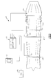
Figure 1 is a general perspective view an exemplary gas turbine engine embodiment for use with the present disclosure; -
Figure 2 is a block diagram of a moisture monitoring system; -
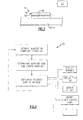
Figure 3 is a schematic view of a sensor for the moisture monitoring system of an exemplary module used to implement an engine power anticipation algorithm; and -
Figure 4 is a flowchart illustrating operation of the moisture monitoring system. -
Figure 1 schematically illustrates agas turbine engine 20. Thegas turbine engine 20 is disclosed herein as a two-spool turbofan that generally incorporates afan section 22, a compressor section 24, acombustor section 26, aturbine section 28, anaugmenter section 30 and anozzle section 32. The sections are defined along a central longitudinal engine axis A. Although depicted as an augmented low bypass gas turbine engine in the disclosed non-limiting embodiment, it should be understood that the concepts described herein are applicable to other gas turbine engines including geared architecture engines, direct drive turbofans, turboshaft engines and others. - The compressor section 24, the
combustor section 26 and theturbine section 28 are generally referred to as the engine core. Thefan section 22 and alow pressure turbine 34 of theturbine section 28 are coupled by afirst shaft 36 to define a low spool. The compressor section 24 and ahigh pressure turbine 38 of theturbine section 28 are coupled by asecond shaft 40 to define a high spool. - An outer
engine case structure 42 and aninner engine structure 44 define a generally annular secondary flow path 46 around acore flow path 48 of the engine core. It should be understood that various structure within the engine may define the outerengine case structure 42 and theinner engine structure 44 which essentially define an exoskeleton to support the core engine therein. - Air which enters the
fan section 22 is divided between a core flow through thecore flow path 48 and a secondary flow through the secondary flow path 46. The core flow passes through thecombustor section 26, theturbine section 28, then theaugmentor section 30 where fuel may be selectively injected and burned to generate additional thrust through thenozzle section 32. The secondary flow may be utilized for a multiple of purposes to include, for example, cooling and pressurization. The secondary flow as defined herein is any flow different from the primary combustion gas exhaust core flow. The secondary flow passes through an annulus defined by the outerengine case structure 42 and theinner engine structure 44 then may be at least partially injected into the core flow adjacent thenozzle section 32. - The outer
engine case structure 42 and theinner engine structure 44 as well as other engine structures are often manufactured of Ceramic Matrix Composite, Organic Matrix Composite materials and combinations thereof which are moisture sensitive. The Ceramic Matrix Composite and the Organic Matrix Composite materials will hereinafter be referred to herein as composite materials but it should be understood that any such moisture sensitive materials and structured are also contemplated. - With reference to
Figure 2 , amoisture monitoring system 50 interfaces with thegas turbine engine 20 in real time to ensure that the moisture content of the composite material is at an acceptable dryness level and that the aircraft may become airborne and maneuver as soon as possibly for emergent situations. Themoisture monitoring system 50 generally includes acontrol 52 and asensor system 54 in communication with thecontrol 52. Thesensor system 54 senses a moisture level and thecontrol 52 determines moisture data from the moisture level for communication to the aircrew. - The
control 52 typically includes aprocessor 52A, amemory 52B, and aninterface 52C. Theprocessor 52A may be any type of microprocessor having desired performance characteristics. Thememory 52B may include any type of computer readable medium which stores the data and control algorithms described herein. Theinterface 52C may include any system that facilitates communication with thesensor system 54 as well as other systems. - In one non-limiting embodiment, the
control 52 may be a Full Authority Digital Electronic Control (FADEC), a portion of a flight control computer (FCC), a stand-alone control module or other controller. Thesensor system 54 may include but not be limited to dielectric moisture meters. - The
sensor system 54 may include a multiple of sensors strategically placed in the composite material structures throughout theengine 20. In one non-limiting embodiment, thesensor system 54 may be specifically located at a high stress location such as aflange sensor system 54 may include any number of sensors positioned at multiple locations. - In one disclosed non-limiting embodiment, the
sensor system 54 is directly embedded within the composite material structures. Although the outerengine case structure 42 and theinner engine structure 44 are illustrated herein, it should be understood that any composite material structure will benefit herefrom. - In another disclosed non-limiting embodiment, the
sensor system 54 may includemountable sensors 56 each of which may include adielectric moisture meter 58 imbedded or otherwise located in acomposite material coupon 60 that is similar or identical in composition to the composite material structures to be monitored (Figure 3 ). Thecomposite material coupon 60 may then be removably or otherwise mounted to the composite material structures at a desired location in a replaceable manner. That is, themountable sensors 56 need not be imbedded directly into the composite material structures as discussed above but are separately mounted thereto. - The
control 52 executes amoisture monitoring algorithm 62. The functions of thealgorithm 62 are disclosed in terms of functional block diagrams inFigure 4 , and it should be understood by those skilled in the art with the benefit of this disclosure that these functions may be enacted in either dedicated hardware circuitry or programmed software routines capable of execution in a microprocessor based electronics control embodiment. When implemented as programmed software routines, the functions ofalgorithm 62 may be tangibly embodied inmemory 52B for execution byprocessor 52A. - The
moisture monitoring system 50 communicates with the aircrew through acockpit display 64 such as a multi-function display to provide moisture data to the aircrew in real time. The moisture data may be of various forms usable by the aircrew such as an a alert, a warning light, a condition status, or other symbology or control functionality which apprises the aircrew of the composite material structure moisture state. - In another non-limiting embodiment, the
system 50 communicates a required idle time prior to takeoff. For example, a countdown time may be presented to the aircrew which counts down to a takeoff time or to a particular G limit capability. Since moisture data is determined essentially in real time, thesystem 50 readily accounts for any local weather anomalies for each individual vehicle. - In another non-limiting embodiment, the
system 50 displays flight limits such as a G limit which allows essentially immediate take off in emergent situations but alerts an aircrew to the G limit which may be exerted while the composite material dries. This permits an aircrew to initiate a mission under restricted G conditions until the composite material dries to full G capability. This is compared to current practices of awaiting a calculated predetermined idle time period on the ground to assure an acceptable moisture level but which may be longer than actually required because the calculate time is based on worst case conditions and is not real time or weather correlated. While the conventional method may be refined to account for average regional weather conditions and other factors, maximum efficiency is still not provided in real time which may make a critical time difference for military aircraft in emergent situations. - In another non-limiting embodiment, the
system 50 communicates directly with aflight control computer 66 to limit the aircraft flight envelop through modification of flight control laws while the composite material is drying to assure the composite material structures are not inadvertently overstressed - It should be understood that like reference numerals identify corresponding or similar elements throughout the several drawings. It should also be understood that although a particular component arrangement is disclosed in the illustrated embodiment, other arrangements will benefit herefrom.
- Although particular step sequences are shown, described, and claimed, it should be understood that steps may be performed in any order, separated or combined unless otherwise indicated and will still benefit from the present disclosure.
- The foregoing description is exemplary rather than defined by the limitations within. Various non-limiting embodiments are disclosed herein, however, one of ordinary skill in the art would recognize that various modifications and variations in light of the above teachings will fall within the scope of the appended claims. It is therefore to be understood that within the scope of the appended claims, the disclosure may be practiced other than as specifically described. For that reason the appended claims should be studied to determine true scope and content.
Claims (15)
- A moisture monitoring system for a gas turbine engine comprising:a composite material structure;a sensor system operable to sense a moisture level in said composite material structure; anda control in communication with said sensor system to determine moisture data from the moisture level.
- The system as recited in claim 1, wherein said sensor system includes a dielectric moisture meter.
- The system as recited in claim 1 or 2, wherein said sensor system is embedded within said composite material structure,
- The system as recited in claim 1 or 2, wherein said sensor system is embedded within a composite material coupon, said composite material coupon being mounted to said composite material structure.
- The system as recited in claim 1, 2, 3 or 4, wherein said composite material structure is an outer engine case structure of the gas turbine engine; preferably wherein said sensor system is located adjacent a flange of said outer engine case structure.
- The system as recited in claim 1, 2, 3 or 4, wherein said composite material structure is an inner engine structure.
- The system as recited in any preceding claim, wherein said control is a Full Authority Digital Electronic Control (FADEC).
- The system as recited in any preceding claim comprising:a cockpit display in communication with said control, said cockpit display operable to display said moisture data.
- The system as recited in any preceding claim, wherein said moisture data includes a G limit.
- The system as recited in any preceding claim, wherein said moisture data includes an idle time prior to takeoff; and/or wherein said moisture data includes a time; and/or wherein said moisture data includes a countdown time.
- The system as recited in any preceding claim, further comprising a flight control computer in communication with said control to limit an aircraft flight envelope in response to said moisture level.
- A method of adjusting flight operations comprising:determining a moisture level within a composite material structure of a gas turbine engine; andcommunicating moisture data related to the moisture level to an aircrew.
- The method as recited in claim 12, further comprising:communicating an idle time as the moisture data.
- The method as recited in claim 12 or 13, further comprising:communicating a G limit as the moisture data.
- The method as recited in claim 12, 13 or 14, further comprising:limiting an aircraft flight envelop in response to said moisture level.
Applications Claiming Priority (1)
| Application Number | Priority Date | Filing Date | Title |
|---|---|---|---|
| US13/097,012 US20120277968A1 (en) | 2011-04-28 | 2011-04-28 | Moisture monitoring system for gas turbine engines |
Publications (3)
| Publication Number | Publication Date |
|---|---|
| EP2518275A2 true EP2518275A2 (en) | 2012-10-31 |
| EP2518275A3 EP2518275A3 (en) | 2017-10-04 |
| EP2518275B1 EP2518275B1 (en) | 2019-09-18 |
Family
ID=46062084
Family Applications (1)
| Application Number | Title | Priority Date | Filing Date |
|---|---|---|---|
| EP12166078.1A Active EP2518275B1 (en) | 2011-04-28 | 2012-04-27 | Moisture monitoring system for gas turbine engines |
Country Status (2)
| Country | Link |
|---|---|
| US (1) | US20120277968A1 (en) |
| EP (1) | EP2518275B1 (en) |
Cited By (1)
| Publication number | Priority date | Publication date | Assignee | Title |
|---|---|---|---|---|
| WO2014197030A3 (en) * | 2013-03-12 | 2015-02-05 | United Technologies Corporation | Expanding shell flow control device |
Family Cites Families (8)
| Publication number | Priority date | Publication date | Assignee | Title |
|---|---|---|---|---|
| US4221962A (en) * | 1978-04-24 | 1980-09-09 | Northrop Corporation | Fiber-optic moisture sensor for composite structures |
| US4379406A (en) * | 1980-09-25 | 1983-04-12 | Bennewitz Paul F | Relative humidity detector systems and method of increasing the calibration period of relative humidity detector systems |
| US6313646B1 (en) * | 1999-02-02 | 2001-11-06 | Dacco Sci, Inc. | In-situ electrochemical-based moisture sensor for detecting moisture in composite and bonded structures |
| US6446357B2 (en) * | 2000-06-30 | 2002-09-10 | Whirlpool Corporation | Fuzzy logic control for an electric clothes dryer |
| CN1259141C (en) * | 2000-07-05 | 2006-06-14 | 株式会社山本制作所 | Rice washing device and non-washing rice manufacturing device |
| US6894512B2 (en) * | 2003-03-24 | 2005-05-17 | Israel Aircraft Industries Ltd. | Method for detecting hidden corrosion and a sensor for use in the same |
| US7236120B2 (en) * | 2005-03-31 | 2007-06-26 | United States Of America As Represented By The Secretary Of Commerce, The National Institute Of Standards And Technology | Ultra-wideband detector systems for detecting moisture in building walls |
| ITTO20070176A1 (en) * | 2007-03-08 | 2008-09-09 | Alenia Aeronautica Spa | ARTICLE OF COMPOSITE MATERIAL WITH TEMPERATURE AND HUMIDITY CONTROL, AND PROCEDURES FOR THE USE OF SUCH ITEM |
-
2011
- 2011-04-28 US US13/097,012 patent/US20120277968A1/en not_active Abandoned
-
2012
- 2012-04-27 EP EP12166078.1A patent/EP2518275B1/en active Active
Non-Patent Citations (1)
| Title |
|---|
| None |
Cited By (1)
| Publication number | Priority date | Publication date | Assignee | Title |
|---|---|---|---|---|
| WO2014197030A3 (en) * | 2013-03-12 | 2015-02-05 | United Technologies Corporation | Expanding shell flow control device |
Also Published As
| Publication number | Publication date |
|---|---|
| US20120277968A1 (en) | 2012-11-01 |
| EP2518275B1 (en) | 2019-09-18 |
| EP2518275A3 (en) | 2017-10-04 |
Similar Documents
| Publication | Publication Date | Title |
|---|---|---|
| EP3418504B1 (en) | Method for health monitoring and gas turbine engine | |
| EP3070562B1 (en) | Gas turbine engine health determination | |
| US20260117709A1 (en) | Controlling a compressor of a turbine engine | |
| US10309317B2 (en) | Air turbine starter pressure monitor system | |
| EP1444428B1 (en) | Method and system for preventing surge events in a gas turbine engine | |
| US12291344B2 (en) | Aircraft performance optimization based on engine performance monitoring | |
| US10822996B2 (en) | Gas turbine engine health determination | |
| US20120316748A1 (en) | Method And Device For Monitoring A Turbine Engine Of An Aircraft | |
| EP1788223B1 (en) | Turbine engine arrangements and control | |
| US11618580B2 (en) | Hybrid electric aircraft engine | |
| EP2589782B1 (en) | Aircraft jet engine system for optimizing power usage from damaged fan blades and corresponding method | |
| EP3450700A1 (en) | Vibration control for a gas turbine engine | |
| US20060241886A1 (en) | Method and apparatus for gas turbine engine ignition systems | |
| CA3019301C (en) | Shaft shear detection for gas turbine engines | |
| EP2518275B1 (en) | Moisture monitoring system for gas turbine engines | |
| EP3219965B1 (en) | Takeoff power management system and method for gas turbine engines | |
| EP3106649B1 (en) | Aircraft gas turbine propulsion engine control without aircraft total air temperature sensors | |
| US12110825B1 (en) | Systems and method for detecting and responding to icing conditions in gas turbine engines | |
| EP4223997B1 (en) | Method and apparatus for measuring compressor bleed flow | |
| EP3447253B1 (en) | Fan stress tracking for turbofan gas turbine engines | |
| EP4273040A1 (en) | Systems and methods for controlling noise in aircraft powered by hybrid-electric gas turbine engines | |
| US20140178175A1 (en) | Air turbine starter monitor system |
Legal Events
| Date | Code | Title | Description |
|---|---|---|---|
| PUAI | Public reference made under article 153(3) epc to a published international application that has entered the european phase |
Free format text: ORIGINAL CODE: 0009012 |
|
| AK | Designated contracting states |
Kind code of ref document: A2 Designated state(s): AL AT BE BG CH CY CZ DE DK EE ES FI FR GB GR HR HU IE IS IT LI LT LU LV MC MK MT NL NO PL PT RO RS SE SI SK SM TR |
|
| AX | Request for extension of the european patent |
Extension state: BA ME |
|
| RAP1 | Party data changed (applicant data changed or rights of an application transferred) |
Owner name: UNITED TECHNOLOGIES CORPORATION |
|
| PUAL | Search report despatched |
Free format text: ORIGINAL CODE: 0009013 |
|
| AK | Designated contracting states |
Kind code of ref document: A3 Designated state(s): AL AT BE BG CH CY CZ DE DK EE ES FI FR GB GR HR HU IE IS IT LI LT LU LV MC MK MT NL NO PL PT RO RS SE SI SK SM TR |
|
| AX | Request for extension of the european patent |
Extension state: BA ME |
|
| RIC1 | Information provided on ipc code assigned before grant |
Ipc: F01D 21/14 20060101ALI20170830BHEP Ipc: G01N 27/12 20060101ALI20170830BHEP Ipc: F01D 17/02 20060101AFI20170830BHEP |
|
| STAA | Information on the status of an ep patent application or granted ep patent |
Free format text: STATUS: REQUEST FOR EXAMINATION WAS MADE |
|
| 17P | Request for examination filed |
Effective date: 20180323 |
|
| RBV | Designated contracting states (corrected) |
Designated state(s): AL AT BE BG CH CY CZ DE DK EE ES FI FR GB GR HR HU IE IS IT LI LT LU LV MC MK MT NL NO PL PT RO RS SE SI SK SM TR |
|
| GRAP | Despatch of communication of intention to grant a patent |
Free format text: ORIGINAL CODE: EPIDOSNIGR1 |
|
| STAA | Information on the status of an ep patent application or granted ep patent |
Free format text: STATUS: GRANT OF PATENT IS INTENDED |
|
| INTG | Intention to grant announced |
Effective date: 20190405 |
|
| GRAS | Grant fee paid |
Free format text: ORIGINAL CODE: EPIDOSNIGR3 |
|
| GRAA | (expected) grant |
Free format text: ORIGINAL CODE: 0009210 |
|
| STAA | Information on the status of an ep patent application or granted ep patent |
Free format text: STATUS: THE PATENT HAS BEEN GRANTED |
|
| AK | Designated contracting states |
Kind code of ref document: B1 Designated state(s): AL AT BE BG CH CY CZ DE DK EE ES FI FR GB GR HR HU IE IS IT LI LT LU LV MC MK MT NL NO PL PT RO RS SE SI SK SM TR |
|
| REG | Reference to a national code |
Ref country code: GB Ref legal event code: FG4D |
|
| REG | Reference to a national code |
Ref country code: CH Ref legal event code: EP |
|
| REG | Reference to a national code |
Ref country code: DE Ref legal event code: R096 Ref document number: 602012064046 Country of ref document: DE |
|
| REG | Reference to a national code |
Ref country code: AT Ref legal event code: REF Ref document number: 1181549 Country of ref document: AT Kind code of ref document: T Effective date: 20191015 |
|
| REG | Reference to a national code |
Ref country code: IE Ref legal event code: FG4D |
|
| REG | Reference to a national code |
Ref country code: NL Ref legal event code: MP Effective date: 20190918 |
|
| PG25 | Lapsed in a contracting state [announced via postgrant information from national office to epo] |
Ref country code: NO Free format text: LAPSE BECAUSE OF FAILURE TO SUBMIT A TRANSLATION OF THE DESCRIPTION OR TO PAY THE FEE WITHIN THE PRESCRIBED TIME-LIMIT Effective date: 20191218 Ref country code: LT Free format text: LAPSE BECAUSE OF FAILURE TO SUBMIT A TRANSLATION OF THE DESCRIPTION OR TO PAY THE FEE WITHIN THE PRESCRIBED TIME-LIMIT Effective date: 20190918 Ref country code: BG Free format text: LAPSE BECAUSE OF FAILURE TO SUBMIT A TRANSLATION OF THE DESCRIPTION OR TO PAY THE FEE WITHIN THE PRESCRIBED TIME-LIMIT Effective date: 20191218 Ref country code: FI Free format text: LAPSE BECAUSE OF FAILURE TO SUBMIT A TRANSLATION OF THE DESCRIPTION OR TO PAY THE FEE WITHIN THE PRESCRIBED TIME-LIMIT Effective date: 20190918 Ref country code: SE Free format text: LAPSE BECAUSE OF FAILURE TO SUBMIT A TRANSLATION OF THE DESCRIPTION OR TO PAY THE FEE WITHIN THE PRESCRIBED TIME-LIMIT Effective date: 20190918 Ref country code: HR Free format text: LAPSE BECAUSE OF FAILURE TO SUBMIT A TRANSLATION OF THE DESCRIPTION OR TO PAY THE FEE WITHIN THE PRESCRIBED TIME-LIMIT Effective date: 20190918 |
|
| REG | Reference to a national code |
Ref country code: LT Ref legal event code: MG4D |
|
| PG25 | Lapsed in a contracting state [announced via postgrant information from national office to epo] |
Ref country code: GR Free format text: LAPSE BECAUSE OF FAILURE TO SUBMIT A TRANSLATION OF THE DESCRIPTION OR TO PAY THE FEE WITHIN THE PRESCRIBED TIME-LIMIT Effective date: 20191219 Ref country code: AL Free format text: LAPSE BECAUSE OF FAILURE TO SUBMIT A TRANSLATION OF THE DESCRIPTION OR TO PAY THE FEE WITHIN THE PRESCRIBED TIME-LIMIT Effective date: 20190918 Ref country code: RS Free format text: LAPSE BECAUSE OF FAILURE TO SUBMIT A TRANSLATION OF THE DESCRIPTION OR TO PAY THE FEE WITHIN THE PRESCRIBED TIME-LIMIT Effective date: 20190918 Ref country code: LV Free format text: LAPSE BECAUSE OF FAILURE TO SUBMIT A TRANSLATION OF THE DESCRIPTION OR TO PAY THE FEE WITHIN THE PRESCRIBED TIME-LIMIT Effective date: 20190918 |
|
| REG | Reference to a national code |
Ref country code: AT Ref legal event code: MK05 Ref document number: 1181549 Country of ref document: AT Kind code of ref document: T Effective date: 20190918 |
|
| PG25 | Lapsed in a contracting state [announced via postgrant information from national office to epo] |
Ref country code: IT Free format text: LAPSE BECAUSE OF FAILURE TO SUBMIT A TRANSLATION OF THE DESCRIPTION OR TO PAY THE FEE WITHIN THE PRESCRIBED TIME-LIMIT Effective date: 20190918 Ref country code: NL Free format text: LAPSE BECAUSE OF FAILURE TO SUBMIT A TRANSLATION OF THE DESCRIPTION OR TO PAY THE FEE WITHIN THE PRESCRIBED TIME-LIMIT Effective date: 20190918 Ref country code: AT Free format text: LAPSE BECAUSE OF FAILURE TO SUBMIT A TRANSLATION OF THE DESCRIPTION OR TO PAY THE FEE WITHIN THE PRESCRIBED TIME-LIMIT Effective date: 20190918 Ref country code: PT Free format text: LAPSE BECAUSE OF FAILURE TO SUBMIT A TRANSLATION OF THE DESCRIPTION OR TO PAY THE FEE WITHIN THE PRESCRIBED TIME-LIMIT Effective date: 20200120 Ref country code: PL Free format text: LAPSE BECAUSE OF FAILURE TO SUBMIT A TRANSLATION OF THE DESCRIPTION OR TO PAY THE FEE WITHIN THE PRESCRIBED TIME-LIMIT Effective date: 20190918 Ref country code: EE Free format text: LAPSE BECAUSE OF FAILURE TO SUBMIT A TRANSLATION OF THE DESCRIPTION OR TO PAY THE FEE WITHIN THE PRESCRIBED TIME-LIMIT Effective date: 20190918 Ref country code: ES Free format text: LAPSE BECAUSE OF FAILURE TO SUBMIT A TRANSLATION OF THE DESCRIPTION OR TO PAY THE FEE WITHIN THE PRESCRIBED TIME-LIMIT Effective date: 20190918 Ref country code: RO Free format text: LAPSE BECAUSE OF FAILURE TO SUBMIT A TRANSLATION OF THE DESCRIPTION OR TO PAY THE FEE WITHIN THE PRESCRIBED TIME-LIMIT Effective date: 20190918 |
|
| PG25 | Lapsed in a contracting state [announced via postgrant information from national office to epo] |
Ref country code: CZ Free format text: LAPSE BECAUSE OF FAILURE TO SUBMIT A TRANSLATION OF THE DESCRIPTION OR TO PAY THE FEE WITHIN THE PRESCRIBED TIME-LIMIT Effective date: 20190918 Ref country code: SM Free format text: LAPSE BECAUSE OF FAILURE TO SUBMIT A TRANSLATION OF THE DESCRIPTION OR TO PAY THE FEE WITHIN THE PRESCRIBED TIME-LIMIT Effective date: 20190918 Ref country code: SK Free format text: LAPSE BECAUSE OF FAILURE TO SUBMIT A TRANSLATION OF THE DESCRIPTION OR TO PAY THE FEE WITHIN THE PRESCRIBED TIME-LIMIT Effective date: 20190918 Ref country code: IS Free format text: LAPSE BECAUSE OF FAILURE TO SUBMIT A TRANSLATION OF THE DESCRIPTION OR TO PAY THE FEE WITHIN THE PRESCRIBED TIME-LIMIT Effective date: 20200224 |
|
| REG | Reference to a national code |
Ref country code: DE Ref legal event code: R097 Ref document number: 602012064046 Country of ref document: DE |
|
| PLBE | No opposition filed within time limit |
Free format text: ORIGINAL CODE: 0009261 |
|
| STAA | Information on the status of an ep patent application or granted ep patent |
Free format text: STATUS: NO OPPOSITION FILED WITHIN TIME LIMIT |
|
| PG2D | Information on lapse in contracting state deleted |
Ref country code: IS |
|
| PG25 | Lapsed in a contracting state [announced via postgrant information from national office to epo] |
Ref country code: DK Free format text: LAPSE BECAUSE OF FAILURE TO SUBMIT A TRANSLATION OF THE DESCRIPTION OR TO PAY THE FEE WITHIN THE PRESCRIBED TIME-LIMIT Effective date: 20190918 Ref country code: IS Free format text: LAPSE BECAUSE OF FAILURE TO SUBMIT A TRANSLATION OF THE DESCRIPTION OR TO PAY THE FEE WITHIN THE PRESCRIBED TIME-LIMIT Effective date: 20200119 |
|
| 26N | No opposition filed |
Effective date: 20200619 |
|
| PG25 | Lapsed in a contracting state [announced via postgrant information from national office to epo] |
Ref country code: SI Free format text: LAPSE BECAUSE OF FAILURE TO SUBMIT A TRANSLATION OF THE DESCRIPTION OR TO PAY THE FEE WITHIN THE PRESCRIBED TIME-LIMIT Effective date: 20190918 |
|
| PG25 | Lapsed in a contracting state [announced via postgrant information from national office to epo] |
Ref country code: MC Free format text: LAPSE BECAUSE OF FAILURE TO SUBMIT A TRANSLATION OF THE DESCRIPTION OR TO PAY THE FEE WITHIN THE PRESCRIBED TIME-LIMIT Effective date: 20190918 |
|
| REG | Reference to a national code |
Ref country code: CH Ref legal event code: PL |
|
| PG25 | Lapsed in a contracting state [announced via postgrant information from national office to epo] |
Ref country code: LU Free format text: LAPSE BECAUSE OF NON-PAYMENT OF DUE FEES Effective date: 20200427 Ref country code: CH Free format text: LAPSE BECAUSE OF NON-PAYMENT OF DUE FEES Effective date: 20200430 Ref country code: LI Free format text: LAPSE BECAUSE OF NON-PAYMENT OF DUE FEES Effective date: 20200430 |
|
| REG | Reference to a national code |
Ref country code: BE Ref legal event code: MM Effective date: 20200430 |
|
| PG25 | Lapsed in a contracting state [announced via postgrant information from national office to epo] |
Ref country code: BE Free format text: LAPSE BECAUSE OF NON-PAYMENT OF DUE FEES Effective date: 20200430 |
|
| PG25 | Lapsed in a contracting state [announced via postgrant information from national office to epo] |
Ref country code: IE Free format text: LAPSE BECAUSE OF NON-PAYMENT OF DUE FEES Effective date: 20200427 |
|
| PG25 | Lapsed in a contracting state [announced via postgrant information from national office to epo] |
Ref country code: TR Free format text: LAPSE BECAUSE OF FAILURE TO SUBMIT A TRANSLATION OF THE DESCRIPTION OR TO PAY THE FEE WITHIN THE PRESCRIBED TIME-LIMIT Effective date: 20190918 Ref country code: MT Free format text: LAPSE BECAUSE OF FAILURE TO SUBMIT A TRANSLATION OF THE DESCRIPTION OR TO PAY THE FEE WITHIN THE PRESCRIBED TIME-LIMIT Effective date: 20190918 Ref country code: CY Free format text: LAPSE BECAUSE OF FAILURE TO SUBMIT A TRANSLATION OF THE DESCRIPTION OR TO PAY THE FEE WITHIN THE PRESCRIBED TIME-LIMIT Effective date: 20190918 |
|
| PG25 | Lapsed in a contracting state [announced via postgrant information from national office to epo] |
Ref country code: MK Free format text: LAPSE BECAUSE OF FAILURE TO SUBMIT A TRANSLATION OF THE DESCRIPTION OR TO PAY THE FEE WITHIN THE PRESCRIBED TIME-LIMIT Effective date: 20190918 |
|
| REG | Reference to a national code |
Ref country code: DE Ref legal event code: R081 Ref document number: 602012064046 Country of ref document: DE Owner name: RAYTHEON TECHNOLOGIES CORPORATION (N.D.GES.D.S, US Free format text: FORMER OWNER: UNITED TECHNOLOGIES CORPORATION, FARMINGTON, CONN., US Ref country code: DE Ref legal event code: R081 Ref document number: 602012064046 Country of ref document: DE Owner name: RTX CORPORATION (N.D.GES.D. STAATES DELAWARE),, US Free format text: FORMER OWNER: UNITED TECHNOLOGIES CORPORATION, FARMINGTON, CONN., US |
|
| P01 | Opt-out of the competence of the unified patent court (upc) registered |
Effective date: 20230520 |
|
| PGFP | Annual fee paid to national office [announced via postgrant information from national office to epo] |
Ref country code: DE Payment date: 20250319 Year of fee payment: 14 |
|
| REG | Reference to a national code |
Ref country code: DE Ref legal event code: R081 Ref document number: 602012064046 Country of ref document: DE Owner name: RTX CORPORATION (N.D.GES.D. STAATES DELAWARE),, US Free format text: FORMER OWNER: RAYTHEON TECHNOLOGIES CORPORATION (N.D.GES.D.STAATES DELAWARE), ARLINGTON, VA, US |
|
| PGFP | Annual fee paid to national office [announced via postgrant information from national office to epo] |
Ref country code: GB Payment date: 20260319 Year of fee payment: 15 |
|
| PGFP | Annual fee paid to national office [announced via postgrant information from national office to epo] |
Ref country code: FR Payment date: 20260320 Year of fee payment: 15 |