EP2517993B1 - Web winders and/or methods of operating a web winder - Google Patents
Web winders and/or methods of operating a web winder Download PDFInfo
- Publication number
- EP2517993B1 EP2517993B1 EP20120166056 EP12166056A EP2517993B1 EP 2517993 B1 EP2517993 B1 EP 2517993B1 EP 20120166056 EP20120166056 EP 20120166056 EP 12166056 A EP12166056 A EP 12166056A EP 2517993 B1 EP2517993 B1 EP 2517993B1
- Authority
- EP
- European Patent Office
- Prior art keywords
- spindle
- endless band
- turret
- winding
- rotation
- Prior art date
- Legal status (The legal status is an assumption and is not a legal conclusion. Google has not performed a legal analysis and makes no representation as to the accuracy of the status listed.)
- Not-in-force
Links
- 238000000034 method Methods 0.000 title claims description 14
- 238000004804 winding Methods 0.000 claims description 45
- 230000007246 mechanism Effects 0.000 claims description 41
- 238000006073 displacement reaction Methods 0.000 claims description 3
- 238000004519 manufacturing process Methods 0.000 description 3
- RTAQQCXQSZGOHL-UHFFFAOYSA-N Titanium Chemical compound [Ti] RTAQQCXQSZGOHL-UHFFFAOYSA-N 0.000 description 2
- 230000009471 action Effects 0.000 description 2
- 230000009467 reduction Effects 0.000 description 2
- 238000012423 maintenance Methods 0.000 description 1
- 230000003252 repetitive effect Effects 0.000 description 1
- 230000001360 synchronised effect Effects 0.000 description 1
Images








Classifications
-
- B—PERFORMING OPERATIONS; TRANSPORTING
- B65—CONVEYING; PACKING; STORING; HANDLING THIN OR FILAMENTARY MATERIAL
- B65H—HANDLING THIN OR FILAMENTARY MATERIAL, e.g. SHEETS, WEBS, CABLES
- B65H19/00—Changing the web roll
- B65H19/22—Changing the web roll in winding mechanisms or in connection with winding operations
- B65H19/2207—Changing the web roll in winding mechanisms or in connection with winding operations the web roll being driven by a winding mechanism of the centre or core drive type
- B65H19/2215—Turret-type with two roll supports
-
- B—PERFORMING OPERATIONS; TRANSPORTING
- B65—CONVEYING; PACKING; STORING; HANDLING THIN OR FILAMENTARY MATERIAL
- B65H—HANDLING THIN OR FILAMENTARY MATERIAL, e.g. SHEETS, WEBS, CABLES
- B65H2403/00—Power transmission; Driving means
- B65H2403/20—Belt drives
-
- B—PERFORMING OPERATIONS; TRANSPORTING
- B65—CONVEYING; PACKING; STORING; HANDLING THIN OR FILAMENTARY MATERIAL
- B65H—HANDLING THIN OR FILAMENTARY MATERIAL, e.g. SHEETS, WEBS, CABLES
- B65H2403/00—Power transmission; Driving means
- B65H2403/90—Machine drive
- B65H2403/94—Other features of machine drive
- B65H2403/942—Bidirectional powered handling device
Definitions
- the invention relates to web winders and/or methods of operating a web winder.
- Slitter rewinding machines are known.
- a prior art example of the Applicant's own slitter rewinding machine is in the marketplace well-known under the reference Titan CT610 (Titan CT610 is a trademark of the applicant).
- Titan CT610 is a trademark of the applicant.
- the turreting function is carried out by two turrets located adjacent one above the other at the unloading portion of the machine. Prior to arriving at this portion of the web winder, the web is slit in a number of sections. Each turret incorporates two spindles.
- the spindle closest to the slitter which is often referred to as the inboard spindle is employed for rewinding the web whilst the spindle further away from the slitter which is often referred to as the outboard spindle is employed to allow unloading of the rewound packages or rolls.
- Rotation of the turret causes the spindles' positions to be exchanged.
- pairs of turrets are synchronously rotated by a common motor mechanism.
- Each individual spindle is equipped with its own rewinding motor so that when a spindle is in its rewinding position, winding can immediately take place and when a spindle is in its unloading position, the motor mechanism operating in conjunction with the spindle is primarily idle.
- EP2039634 A known prior art document has been published as EP2039634 .
- the closest prior art is represented by GB 1 382 136 .
- prior art slitter rewinder machines are overly complex.
- One aspect of the invention is to offer alternative configurations which allow simplification of the mechanisms.
- a simplification of the drive mechanism would allow reductions in overall weight of the machines.
- a further problem which has been identified with regard to the prior art is that rewind mandrels on a turret are generally driven at the same speeds. Changes in configuration would allow a greater range of operation capabilities for individual slitter rewinder machines. Such greater flexibility would also allow improved slitter rewinders to have reduced maintenance times.
- the application seeks to remove the traditional limits on rewind roll diameter imposed by previous designs. Any increase in rewind roll diameters would allow greater productivity and flexibility of production.
- the invention provides a web winder comprising a frame; at least one turret rotatably mounted in said frame; said turret incorporating a plate from which first and second winding spindles extend; said turret being rotatable between a first position where said first spindle is in a winding position and said second spindle is in an unloading position; and a second position where said first spindle is in an unloading position and said second spindle is in a winding position; wherein said turret incorporates a driving mechanism configured to engage with whichever spindle is in said winding position; whereby whichever spindle is in said winding position is driven by said mechanism; said driving mechanism incorporating a winding motor which drives the displacement of an endless band which engages a portion of whichever spindle is in the winding position; characterised in that said first and second spindle are provided within the path defined by said endless band; one of said spindles being in contact with the endless band in
- This configuration is particularly advantageous because it allows simplification of the winding mechanism. This will reduce the configuration of the electrical supply to the driving mechanism. It is also particularly advantageous as providing a relatively compact mechanism which is ideally suited for handling large packages of web material.
- the path of said endless band is defined between said first spindle in the winding position on one side of the path, and at least two pulleys at the opposite side of the path.
- said path is further defined by two guide rollers equipped with a tensioner.
- said path is further defined by two guide rollers equipped with a tensioner.
- said driving mechanism incorporates a winding motor which drives the displacement of an endless band which engages a portion of whichever spindle is in the winding position.
- Said endless band may be a drive belt.
- said winding motor drives a first endless band and a second endless band which are arranged in sequence; said first endless band being arranged between said motor and a pulley and said second endless band being arranged between said pulley and a portion of said spindle to drive said spindle.
- regularly spaced-apart guide rollers are provided to engage said endless band. This configuration allows the tension in the belt or band to be maintained during the turreting rotation. It also allows the belt to be sufficiently spaced apart to allow spindles to be displaced to and from their winding engagement position.
- two oppositely located guide rollers are provided to engage said endless band and a tensioner is arranged between said guide rollers. This configuration is particularly advantageous in order to maintain the tension and appropriate engagement to the spindle.
- said spindles incorporate means for locking one or more roll cores on a spindle; and said winder further comprises a motor configured to drive the rotation of said spindles when in said unload position in the opposite direction of the winding direction of the spindle in the winding position; whereby roll cores are unlocked from their corresponding spindle prior to unloading.
- a motor configured to drive the rotation of said spindles when in said unload position in the opposite direction of the winding direction of the spindle in the winding position; whereby roll cores are unlocked from their corresponding spindle prior to unloading.
- said motor drives the rotation of an endless band which is brought to and from a portion of a spindle in the unloading position; whereby once the band, in use, engages said portion of a spindle, rotation of said spindle arises.
- Said spindle portion incorporates a gear with corresponding teeth; and said endless band may be a chain, the chain being configured to mesh with the teeth of said gear. This allows rapid rotational engagement with the spindle at the unloading station for short bursts of rotation.
- the winder incorporates N turrets and M motors are provided to drive the rotation of said turrets. This allows neighbouring turrets to be rotated independently if necessary. This configuration will also allow simultaneous rotation provided the control of the turrets and motors synchronise the rotation.
- said plate is a gear and said motor is coupled to said gear via a gear. This allows simplified connection between a driving motor and a plate.
- said winder incorporates a controller which is configured to asynchronously rotate turrets. This configuration is particularly advantageous since it will allow a first turret to rotate a rewound package into a position to avoid collision when the second turret with its rewound package is rotated.
- said controller is configured to rotate a first turret by an angle greater than 90° but less than 180° and thereafter rotate a second turret by an angle greater than 90° but less than 180° prior to the turret's completing their rotation between first and second positions.
- This configuration is also particularly advantageous in order to advantageously position one turret relative to the other when displacing rewound packages to their unloading positions.
- the invention provides a method of operating a web winder according to any of the preceding aspects, comprising the steps of:
- the method further comprises the step of driving the rotation of said spindles when in said unloading position in the opposite direction of the winding direction of the spindle in the winding position. Whereby roller cores are unlocked from their corresponding spindle prior to unloading. This reduces or entirely removes the need for manual intervention with rewound packages. It allows for removal or rewound packages at a greater velocity than would otherwise be expected.
- said web winder incorporates at least two levering turrets and the method comprises the step of asynchronously rotating said turrets. This allows relatively larger rewound packages to be produced within the design constraints of a turret.
- said method comprises the step of rotating a first turret by an angle greater than 90° but less than 180° and thereafter rotating a second turret by an angle greater than 90° but less than 180° prior to the turrets completing their rotation between first and second positions.
- the invention provides a web winder comprising a frame. At least two turrets rotatably mounted in said frame; said turrets incorporating a plate from which first and second winding spindles extend; said turrets being rotatable between a first position where said first spindle is in a winding position and said second spindle is in an unloading position; and a second position where said first spindle is in an unloading position and said second spindle is in a winding position; characterised in that each turret incorporates a separate driving mechanism configured to rotate its corresponding turret independently from any neighbouring turret.
- a controller is provided to asynchronously rotate. This configuration would be particularly advantageous in order to allow turreting to occur with rewound packages of greater diameter than would otherwise be achievable for a given spacing between adjacent turrets.
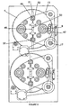
- FIG. 1 shows a pair of turrets and their corresponding drive mechanisms arranged in a support frame 1.
- Turrets 2 and 3 are identical, therefore for simplicity the turreting mechanism of turret 2 is the only one described in any detail.
- Turret 2 is rotatably mounted on supporting frame 1 and incorporates a geared turreting plate 4 which supports spindles 5 and 6.
- Turreting plate 4 incorporates an array of closely contiguous gear teeth 7 projecting radially outwards and disposed about the circumference of the disc-shaped plate. These teeth progressively narrow in width in order to readily mesh with corresponding teeth 8 of a drive wheel 9 which is driven by turreting motor 10.
- the turreting motor is secured onto support frame 1 or another appropriately configured support and drives the rotation of turret 2 independently from the rotation of turret 3 which has its own drive mechanism.
- a primary drive motor 11 is secured to the support frame 1 or another appropriately configured support.
- This motor may preferably be an electric motor which has sufficient power properties to carry out the rewinding operations. Whilst not visible in the figure, the motor 11 incorporates a motor output shaft which drives the rotation of an associated pulley.
- Primary drive belt 12 transmits the rotation from the output shaft pulley to an intermediary pulley assembly 14.
- the intermediary pulley assembly 14, as shown in figure 2 is formed from two juxtaposed pulleys for synchronous rotation respectively referenced 15 and 16. Pulley 15 is of greater diameter than pulley 16. Pulley 15 receives the primary drive belt 12 whilst pulley 16 receives the secondary drive belt 13.
- the intermediary pulley assembly is mounted relative to the support frame and about a shaft 17.
- the secondary drive belt 13 primarily engages pulley 18 of spindle 5 when spindle 5 is in its rewind position.
- Pulley 18 is synchronously rotatable with spindle 5.
- a further pulley 19 is located remotely from both pulley 18 and intermediary pulley assembly 14 so that secondary drive belt 13 is sufficiently spaced apart to allow the turret rotation as the spindles exchange positions.
- spindle pulley 18 and further pulley 19 a number of rollers 21, 22, 23, 24, 25 and 26 are disposed about a circular path on said turret plate 4. These rollers are provided to engage the drive belt 13 particularly during the rotation of the turreting plate 4. Rollers 22 and 25 operate as part of a drive belt tensioning mechanism.
- Rollers 22 and 25 are displaceable in or relative to a channel 27 extending radially across the diameter of plate 4.
- the other rollers 21, 23, 24 and 26 incorporate a shaft such as shaft 28 about which roller 21 is rotatable and which secures the roller to the turreting plate 4.
- Roller 25 by contrast is secured to a mount 29 located beneath the roller.
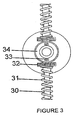
- a boss 30 projects from the mount and roller assembly into an end portion of a helical spring 31 which extends in channel 27 (see figure 1 ).
- the spring is secured against a nut 32.
- the nut is displaceable on the threaded rod 33 which is locked into a spigot 34 which is integral with the turreting plate 4.
- the tension of the spring 31 may be adjusted. Consequently, by adjusting the tension in spring 31, the tension in secondary drive belt 13 is adjusted.
- a similar tensioning mechanism is employed for both roller 22 and 25. This configuration allows the secondary drive belt 13 to engage with the pulley 18 of spindle 5 in order to drive the rewinding operation.
- the secondary drive belt remains in its position in order to allow the rewinding to be effected on spindle 6 once the turret has gone through a rotation of 180°.
- a secondary drive mechanism Whilst the entire rewinding operation of a turret is driven by the primary drive motor 11, a secondary drive mechanism is provided at the unloading side of the turret.
- This secondary drive mechanism incorporates a motor which may be preferably coupled to a gearbox and which may also preferably be an electric motor.
- the motor and gear box assembly 35 drives the rotation of a drive chain 36 (as shown in figure 4 ).
- the drive chain 36 is held between two sprockets 37 and 38.
- Sprocket 38 is driven whilst sprocket 37 is a non-driven follower.
- the chain and sprocket assembly is secured to a lever 39 which is pivotally attached to a supporting member which may be an integral part of the motor and gearbox assembly.
- an actuator 41 is employed to displace the drive chain to and from gear 42 provided on spindle 6.
- the lever causes the drive chain to engage the gear 42, the spindle is rotated for a short period of time.
- the short period of time is usually selected to be sufficient to cause the ball locks, which known machines are already equipped with, to unlock.
- Actuator 41 may be any form of actuator but may preferably be a pneumatic cylinder which attaches at one end to the lever and at another end to a spigot 43 to secure the actuator to the supporting frame.
- Other forms of actuator may incorporate a threaded longitudinally extendable contraption, an electric actuator, or a hydraulic ram.
- the non-driven sprocket is held in an oblong aperture 44 of the lever 39.
- the oblong aperture 44 allows the tension of the chain to be adjusted provided the manner in which the sprocket is secured to the lever is adjustable.
- the lever incorporates two longitudinal portions, the first extending from the bearing upwards and the second being offset laterally in order to provide sufficient clearance for the upper pulley 19.
- a secondary drive mechanism incorporates an electric motor which may have a rating of 500 Watts in order to drive a gearbox.
- the turreting motor provided for each turret may be an electric motor with a rating of 200 Watts and is configured to mesh directly with the gear ring on the geared turreting plate 4.
- this embodiment shows the secondary drive mechanism fitted to the unloading station of the turret, this mechanism is optional.
- the invention envisages a web winder which may incorporate individual driving mechanisms for each turret and/or a drive mechanism for rewinding which engages and disengages with spindles as they are brought to and from their rewinding position.
- Figures 5 show a number of views of a turret through various phases of operation.
- Figure 5A shows spindle 5 in its rewinding position and spindle 6 in its unloading position.
- primary drive belt 12 causes the rotation of secondary drive belt 13.
- the machine is equipped with the means to stop automatically when the set diameter of the rewound rolls is accomplished.
- the turreting motor 10 causes the rotation of its associated gear 9 which causes the turret plate 4 to rotate as indicated by arrow 45.
- Figure 5B shows the turret having rotated by 90°. In this configuration, the guide rollers and drive belt tension assembly collaborate to maintain the tension in the secondary belt 13.
- Figure 5C shows the turret having completed a 180° rotation.
- the rotation induced by motor 10 stops.
- the spindle 6 is now ready for rewinding whilst spindle 5 is outboard and ready to be unloaded.
- Spindle 6 will already be fitted with rewind cores in order to allow rewinding to take place.
- the cylinder 41 retracts, causing lever 39 to engage the drive chain 36 with the rewind spindle drive gear 42.
- the electric motor with gearbox 35 is enabled.
- the gearbox moves the drive chain slowly to ensure the drive chain and rewind spindle drive gear have positive engagement.
- the rewind spindle drive gear is rotated in the opposite direction to rewinding as shown by arrow 46 when contrasted with arrow 47.
- the rotation in the direction shown by arrow 46 will cause the ball locks to unlock and allow the rewound rolls to be removed from the spindle.
- the primary drive electric motor 11 starts when the inboard spindle begins to rewind.
- FIGS 6 , 7 and 8 all show an alternative embodiment of the invention where the belt tensioning assembly and the optional secondary drive mechanism have been modified when compared to the embodiment of the previous figures. Other components have remained identical and are therefore not described in any detail in the context of this new embodiment.
- the drive belt tensioning mechanism 48 incorporates two rollers 49 and 50 which engage secondary drive belt 13 at opposite ends of the drive belt tensioning mechanism.
- a back plate 51 is housed in a machined channel extending across the diameter of the geared turreting plate 4.
- the tension roller block 52 is attached to the back plate 51.
- a threaded rod 53 incorporates internal threading at both ends and is attached by an upper and lower bracket 54 and 55 to the geared turreting plate 4.
- Rods 56 and 57 are screwed into each end of the threaded rod. These rods incorporate an eye 58 and 59. One eye end rod is right hand thread and the other is left hand thread. Each eye end rod is fitted with a nut such as nuts 60 and 61 for locking the nut into position. The tension may be adjusted by loosening the lock nut and subsequently tightening the lock nut once an appropriate tension level is reached.
- FIG. 8 shows the details of an optional secondary drive mechanism generally referenced 62.
- this mechanism incorporates an electric motor 63 which drives a lower sprocket 63 which is joined to an upper sprocket 65 by a chain 66.
- the chain may be brought into contact with the gear ring 42 of spindle 6.
- the upper sprocket is non-driven.
- a lever 67 is rotatably mounted to the drive belt pulley assembly shaft 17.
- the lever is T-shaped with a main upwardly extending portion with two laterally extending portions 68 and 69.
- the upper sprocket 65 is secured to portion 69 whilst an end portion 71 of a pneumatic cylinder is rotatably secured to portion 68.
- Opposite end 72 of cylinder 70 secures the cylinder to a support frame.
- lever 67 is caused to bring chain 66 in contact with gear 42.
- lever 67 retracts, lever 67 disengages chain 66.
- Figures 9 show a turret at various stages of operation.
- Figure 9A shows spindle 5 in the rewinding position. Means may be provided to automatically stop the machine when a set diameter of rewound rolls is reached. Motor 10 then initiates causing the rotation of gear 9 and the consequential rotation of plate 4.
- Figure 9B shows the turret having rotated by 90° whilst Figure 9C shows the turret having rotated by 180°.
- the guide rollers' pulleys maintain the turreting assembly drive belt tension and length.
- Figure 9E shows a view where the cylinder 70 retracts pulling lever 67 and disengages the drive chain from the outboard spindle.
- the electric motor with gearbox is disabled and the outboard rewind mandrel drive gear stops rotating.
- the inboard rewind spindle is caused to accelerate to the set maximum running speed.
- an appropriately configured control system allows a first turret to rotate independently from a second turret. This would allow rewound rolls to be of greater diameter than would otherwise be possible for a given geometry of web winder and rewound rolls. Alternatively, it would allow adjacent turrets to be located closer than would otherwise be possible for a given diameter size of production.
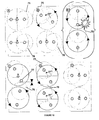
- Figures 10 show a possible sequence of independent rotations which may be followed to achieve the improvements.
- an upper and lower turret holds rewound rolls such as roll 75 and 76.
- the view shown illustrates only one roll per spindle, in practice, a plurality of rolls is provided on each spindle.
- the upper turret may be rotated by 150°.
- the lower turret is rotated by 150° which allows rewound roll 76 to clear spindle 77 of the upper turret.
- rewound rolls 75 and 76 can now be readily brought into the outboard position for unloading as shown in Figure 10E .
- Figure 11 shows an alternative embodiment to the embodiment of figure 1 .
- this configuration instead of providing rollers arranged in a circular array, there are provided only two oppositely disposed rollers 22 and 25 both of which are secured to tensioners of the kind described in detail in figure 3 .
- Figures 12 show a turret at various stages of operation.
- Figure 12A shows spindle 5 in the rewinding position. Means may be provided to automatically stop the machine when a set diameter of rewound rolls is reached. Motor 10 then initiates causing the rotation of gear 9 and the consequential rotation of plate 4.
- Figure 12B shows the turret having rotated by 90° whilst Figure 12C shows the turret having rotated by 180°. As shown in Figure 12B the two guide rollers' pulleys and tensioners maintain the turreting assembly drive belt tension and length.
- Figure 12E shows a view where the cylinder 70 extends pushing lever 67 and disengages the drive chain from the outboard spindle.
- the electric motor with gearbox is disabled and the outboard rewind mandrel drive gear stops rotating.
- the inboard rewind spindle is caused to accelerate to the set maximum running speed.
Landscapes
- Replacement Of Web Rolls (AREA)
Description
- The invention relates to web winders and/or methods of operating a web winder.
- Slitter rewinding machines are known. For example, a prior art example of the Applicant's own slitter rewinding machine is in the marketplace well-known under the reference Titan CT610 (Titan CT610 is a trademark of the applicant). In such machines, the turreting function is carried out by two turrets located adjacent one above the other at the unloading portion of the machine. Prior to arriving at this portion of the web winder, the web is slit in a number of sections. Each turret incorporates two spindles. The spindle closest to the slitter which is often referred to as the inboard spindle is employed for rewinding the web whilst the spindle further away from the slitter which is often referred to as the outboard spindle is employed to allow unloading of the rewound packages or rolls. Rotation of the turret causes the spindles' positions to be exchanged. In the prior art arrangement, pairs of turrets are synchronously rotated by a common motor mechanism. Each individual spindle is equipped with its own rewinding motor so that when a spindle is in its rewinding position, winding can immediately take place and when a spindle is in its unloading position, the motor mechanism operating in conjunction with the spindle is primarily idle.
- A known prior art document has been published as
EP2039634 . - The closest prior art is represented by
GB 1 382 136 - Generally, prior art slitter rewinder machines are overly complex. One aspect of the invention is to offer alternative configurations which allow simplification of the mechanisms. In particular, a simplification of the drive mechanism would allow reductions in overall weight of the machines. A further problem which has been identified with regard to the prior art is that rewind mandrels on a turret are generally driven at the same speeds. Changes in configuration would allow a greater range of operation capabilities for individual slitter rewinder machines. Such greater flexibility would also allow improved slitter rewinders to have reduced maintenance times. In certain aspects, the application seeks to remove the traditional limits on rewind roll diameter imposed by previous designs. Any increase in rewind roll diameters would allow greater productivity and flexibility of production.
- Problems with existing turreting functions have been identified which are addressed which are alternative configurations of slitter rewinders.
- The following specific problems are identified in the prior art:
- Existing slitter rewinding machines have the drawback of rewinding only to a diameter which allows sufficient clearance between rolls of neighbouring turrets so that during simultaneous turreting no collision occurs. If adequate clearance is not provided, overlapping rolls would collide due to the minute imperfections in a roll. Necessarily increasing the distance between neighbouring turrets in order to allow increased roll diameter is not desirable since this would increase manufacturing costs and the floor space the machine would occupy.
- Since each existing rewind mandrel or spindle incorporates a dedicated rewind motor the equipment required to maintain electrical supply to each rewind motor is particularly complex as the motors will move through 180° when the rewind mandrels are turreted.
- In an existing machine rewind mandrels are mounted through the turreting plate. An integral spigot protrudes from the turreting plate centre point. The turreting plate integral spigot accommodates the complicated arrangement of electrical brushes and the belt driven turreting pulley. This means that when the rewind mandrels turret, the rewind motors and belts will have to turret around the turreting plate spigot. To avoid the electrical cable supplying the rewind motors getting tangles around the turreting plate spigot, a complicated and expensive arrangement of brushes is used.
- A single mechanism is used to turret both rewind turrets at the same time.
- The problems and drawbacks outlined with regard to the prior art are only part of the problems the invention seeks to address. Other problems will become apparent to the skilled person when implementing the embodiments which follow.
- In a first broad independent aspect, the invention provides a web winder comprising a frame; at least one turret rotatably mounted in said frame; said turret incorporating a plate from which first and second winding spindles extend; said turret being rotatable between a first position where said first spindle is in a winding position and said second spindle is in an unloading position; and a second position where said first spindle is in an unloading position and said second spindle is in a winding position; wherein said turret incorporates a driving mechanism configured to engage with whichever spindle is in said winding position; whereby whichever spindle is in said winding position is driven by said mechanism; said driving mechanism incorporating a winding motor which drives the displacement of an endless band which engages a portion of whichever spindle is in the winding position; characterised in that said first and second spindle are provided within the path defined by said endless band; one of said spindles being in contact with the endless band in the winding position whilst the other spindle is spaced from the endless band whilst remaining within the path defined by said endless band.
- This configuration is particularly advantageous because it allows simplification of the winding mechanism. This will reduce the configuration of the electrical supply to the driving mechanism. It is also particularly advantageous as providing a relatively compact mechanism which is ideally suited for handling large packages of web material.
- In a subsidiary aspect, the path of said endless band is defined between said first spindle in the winding position on one side of the path, and at least two pulleys at the opposite side of the path. This configuration provides a substantially triangular path in at least one embodiment.
- In a subsidiary aspect, said path is further defined by two guide rollers equipped with a tensioner. In this configuration, there is an advantageous reduction in the potential number of rollers whilst retaining a spindle enveloping path arrangement.
- In a subsidiary aspect in accordance with the first broad independent aspect, said driving mechanism incorporates a winding motor which drives the displacement of an endless band which engages a portion of whichever spindle is in the winding position. Said endless band may be a drive belt. This configuration is particularly advantageous in allowing repetitive engagement and disengagement of the driving mechanism with whichever spindle is in the winding position. It also achieves advantageous control of the winding rotation.
- In a further subsidiary aspect, said winding motor drives a first endless band and a second endless band which are arranged in sequence; said first endless band being arranged between said motor and a pulley and said second endless band being arranged between said pulley and a portion of said spindle to drive said spindle. This configuration is particularly advantageous in terms of achieving the necessary torque on a spindle.
- In a further subsidiary aspect, regularly spaced-apart guide rollers are provided to engage said endless band. This configuration allows the tension in the belt or band to be maintained during the turreting rotation. It also allows the belt to be sufficiently spaced apart to allow spindles to be displaced to and from their winding engagement position.
- In a further subsidiary aspect, two oppositely located guide rollers are provided to engage said endless band and a tensioner is arranged between said guide rollers. This configuration is particularly advantageous in order to maintain the tension and appropriate engagement to the spindle.
- In a further subsidiary aspect, said spindles incorporate means for locking one or more roll cores on a spindle; and said winder further comprises a motor configured to drive the rotation of said spindles when in said unload position in the opposite direction of the winding direction of the spindle in the winding position; whereby roll cores are unlocked from their corresponding spindle prior to unloading. This avoids or at least limits any requirement for manual intervention for unlocking the rolls. This would reduce the requirements for spindles having to be at an easily accessible height for an operator to manually unlock rolls.
- In a further subsidiary aspect, said motor drives the rotation of an endless band which is brought to and from a portion of a spindle in the unloading position; whereby once the band, in use, engages said portion of a spindle, rotation of said spindle arises. Said spindle portion incorporates a gear with corresponding teeth; and said endless band may be a chain, the chain being configured to mesh with the teeth of said gear. This allows rapid rotational engagement with the spindle at the unloading station for short bursts of rotation.
- In a further subsidiary aspect, the winder incorporates N turrets and M motors are provided to drive the rotation of said turrets. This allows neighbouring turrets to be rotated independently if necessary. This configuration will also allow simultaneous rotation provided the control of the turrets and motors synchronise the rotation.
- In a further subsidiary aspect, said plate is a gear and said motor is coupled to said gear via a gear. This allows simplified connection between a driving motor and a plate.
- In a further subsidiary aspect, said winder incorporates a controller which is configured to asynchronously rotate turrets. This configuration is particularly advantageous since it will allow a first turret to rotate a rewound package into a position to avoid collision when the second turret with its rewound package is rotated.
- In a further subsidiary aspect, said controller is configured to rotate a first turret by an angle greater than 90° but less than 180° and thereafter rotate a second turret by an angle greater than 90° but less than 180° prior to the turret's completing their rotation between first and second positions. This configuration is also particularly advantageous in order to advantageously position one turret relative to the other when displacing rewound packages to their unloading positions.
- In a second broad independent aspect, the invention provides a method of operating a web winder according to any of the preceding aspects, comprising the steps of:
- Providing a winding mechanism configured to drive whichever spindle is in a winding position;
- Engaging a first spindle to drive its winding rotation; and
- Disengaging said first spindle and engaging said second spindle by rotating said turret. This method reduces the complexity of operation.
- In a further subsidiary aspect, the method further comprises the step of driving the rotation of said spindles when in said unloading position in the opposite direction of the winding direction of the spindle in the winding position. Whereby roller cores are unlocked from their corresponding spindle prior to unloading. This reduces or entirely removes the need for manual intervention with rewound packages. It allows for removal or rewound packages at a greater velocity than would otherwise be expected.
- In a further subsidiary aspect, said web winder incorporates at least two levering turrets and the method comprises the step of asynchronously rotating said turrets. This allows relatively larger rewound packages to be produced within the design constraints of a turret.
- In a further subsidiary aspect, said method comprises the step of rotating a first turret by an angle greater than 90° but less than 180° and thereafter rotating a second turret by an angle greater than 90° but less than 180° prior to the turrets completing their rotation between first and second positions. This method provides an optimal range for avoiding collision during asynchronous turreting.
- In a further broad independent aspect, the invention provides a web winder comprising a frame. At least two turrets rotatably mounted in said frame; said turrets incorporating a plate from which first and second winding spindles extend; said turrets being rotatable between a first position where said first spindle is in a winding position and said second spindle is in an unloading position; and a second position where said first spindle is in an unloading position and said second spindle is in a winding position; characterised in that each turret incorporates a separate driving mechanism configured to rotate its corresponding turret independently from any neighbouring turret. A controller is provided to asynchronously rotate. This configuration would be particularly advantageous in order to allow turreting to occur with rewound packages of greater diameter than would otherwise be achievable for a given spacing between adjacent turrets.
-
-
Figure 1 shows an elevation view of two neighbouring turrets and their corresponding drive mechanism. -
Figure 2 shows a side elevation of an assembly of pulleys. -
Figure 3 shows an elevation view of a portion of a tensioner. -
Figure 4 shows an exploded view of an unlocking mechanism. -
Figures 5 show respective elevation views of a turret at different stages of operation as the turret rotates by 180°. -
Figure 6 shows an elevation view of turrets with an alternative unlocking mechanism. -
Figure 7 shows an alternative embodiment of a tensioner in an elevation view. -
Figure 8 shows an alternative embodiment of an unlocking mechanism operating on a spindle in the unloading position. -
Figures 9 show a sequence of elevation views of a turret at different stages of the turreting operation. -
Figures 10 show a plurality of schematic views of an asynchronous turreting operation. -
Figure 11 shows an elevation view of two neighbouring turrets and their corresponding drive mechanism in accordance with a second embodiment of the invention. -
Figures 12 show a sequence of elevation views of a turret at different stages of the turreting operation in accordance with a second embodiment of the invention. -
Figure 1 shows a pair of turrets and their corresponding drive mechanisms arranged in a support frame 1.Turrets turret 2 is the only one described in any detail.Turret 2 is rotatably mounted on supporting frame 1 and incorporates a gearedturreting plate 4 which supportsspindles Turreting plate 4 incorporates an array of closelycontiguous gear teeth 7 projecting radially outwards and disposed about the circumference of the disc-shaped plate. These teeth progressively narrow in width in order to readily mesh withcorresponding teeth 8 of adrive wheel 9 which is driven by turretingmotor 10. The turreting motor is secured onto support frame 1 or another appropriately configured support and drives the rotation ofturret 2 independently from the rotation ofturret 3 which has its own drive mechanism. - A
primary drive motor 11 is secured to the support frame 1 or another appropriately configured support. This motor may preferably be an electric motor which has sufficient power properties to carry out the rewinding operations. Whilst not visible in the figure, themotor 11 incorporates a motor output shaft which drives the rotation of an associated pulley. In order to increase the torque applied on the rewinding spindle, a combination of aprimary drive belt 12 and asecondary drive belt 13 is envisaged.Primary drive belt 12 transmits the rotation from the output shaft pulley to anintermediary pulley assembly 14. Theintermediary pulley assembly 14, as shown infigure 2 , is formed from two juxtaposed pulleys for synchronous rotation respectively referenced 15 and 16.Pulley 15 is of greater diameter thanpulley 16.Pulley 15 receives theprimary drive belt 12 whilstpulley 16 receives thesecondary drive belt 13. The intermediary pulley assembly is mounted relative to the support frame and about ashaft 17. - The
secondary drive belt 13 primarily engagespulley 18 ofspindle 5 whenspindle 5 is in its rewind position.Pulley 18 is synchronously rotatable withspindle 5. Afurther pulley 19 is located remotely from bothpulley 18 andintermediary pulley assembly 14 so thatsecondary drive belt 13 is sufficiently spaced apart to allow the turret rotation as the spindles exchange positions. In addition to thepulley assembly 14,spindle pulley 18 andfurther pulley 19, a number ofrollers turret plate 4. These rollers are provided to engage thedrive belt 13 particularly during the rotation of theturreting plate 4.Rollers Rollers channel 27 extending radially across the diameter ofplate 4. Theother rollers shaft 28 about whichroller 21 is rotatable and which secures the roller to theturreting plate 4.Roller 25 by contrast is secured to amount 29 located beneath the roller. - As shown in
Figure 3 , aboss 30 projects from the mount and roller assembly into an end portion of ahelical spring 31 which extends in channel 27 (seefigure 1 ). At the opposite end ofspring 31, the spring is secured against anut 32. The nut is displaceable on the threadedrod 33 which is locked into aspigot 34 which is integral with theturreting plate 4. By rotating or causing the rotation ofnut 32, the tension of thespring 31 may be adjusted. Consequently, by adjusting the tension inspring 31, the tension insecondary drive belt 13 is adjusted. A similar tensioning mechanism is employed for bothroller secondary drive belt 13 to engage with thepulley 18 ofspindle 5 in order to drive the rewinding operation. During the rotation of the turret in order to causespindle 5 to exchange its position withspindle 6, the secondary drive belt remains in its position in order to allow the rewinding to be effected onspindle 6 once the turret has gone through a rotation of 180°. - Whilst the entire rewinding operation of a turret is driven by the
primary drive motor 11, a secondary drive mechanism is provided at the unloading side of the turret. This secondary drive mechanism incorporates a motor which may be preferably coupled to a gearbox and which may also preferably be an electric motor. The motor andgear box assembly 35 drives the rotation of a drive chain 36 (as shown infigure 4 ). Thedrive chain 36 is held between twosprockets Sprocket 38 is driven whilstsprocket 37 is a non-driven follower. The chain and sprocket assembly is secured to alever 39 which is pivotally attached to a supporting member which may be an integral part of the motor and gearbox assembly. This may be facilitated by the provision of abearing 40 at one extremity of the lever. At the opposite extremity of the lever, anactuator 41 is employed to displace the drive chain to and fromgear 42 provided onspindle 6. When the lever causes the drive chain to engage thegear 42, the spindle is rotated for a short period of time. The short period of time is usually selected to be sufficient to cause the ball locks, which known machines are already equipped with, to unlock.Actuator 41 may be any form of actuator but may preferably be a pneumatic cylinder which attaches at one end to the lever and at another end to aspigot 43 to secure the actuator to the supporting frame. Other forms of actuator may incorporate a threaded longitudinally extendable contraption, an electric actuator, or a hydraulic ram. The non-driven sprocket is held in anoblong aperture 44 of thelever 39. Theoblong aperture 44 allows the tension of the chain to be adjusted provided the manner in which the sprocket is secured to the lever is adjustable. The lever incorporates two longitudinal portions, the first extending from the bearing upwards and the second being offset laterally in order to provide sufficient clearance for theupper pulley 19. - A secondary drive mechanism incorporates an electric motor which may have a rating of 500 Watts in order to drive a gearbox. The turreting motor provided for each turret may be an electric motor with a rating of 200 Watts and is configured to mesh directly with the gear ring on the geared
turreting plate 4. - Whilst this embodiment shows the secondary drive mechanism fitted to the unloading station of the turret, this mechanism is optional. The invention envisages a web winder which may incorporate individual driving mechanisms for each turret and/or a drive mechanism for rewinding which engages and disengages with spindles as they are brought to and from their rewinding position.
-
Figures 5 show a number of views of a turret through various phases of operation.Figure 5A showsspindle 5 in its rewinding position andspindle 6 in its unloading position. In this configuration,primary drive belt 12 causes the rotation ofsecondary drive belt 13. The machine is equipped with the means to stop automatically when the set diameter of the rewound rolls is accomplished. At which point, theturreting motor 10 causes the rotation of its associatedgear 9 which causes theturret plate 4 to rotate as indicated byarrow 45.Figure 5B shows the turret having rotated by 90°. In this configuration, the guide rollers and drive belt tension assembly collaborate to maintain the tension in thesecondary belt 13. -
Figure 5C shows the turret having completed a 180° rotation. When the turret reaches this position the rotation induced bymotor 10 stops. Thespindle 6 is now ready for rewinding whilstspindle 5 is outboard and ready to be unloaded.Spindle 6 will already be fitted with rewind cores in order to allow rewinding to take place. - As the rewinding takes place on
spindle 6, as shown inFigure 5D , thecylinder 41 retracts, causinglever 39 to engage thedrive chain 36 with the rewindspindle drive gear 42. Just before the drive chain and rewind spindle drive gear engage, the electric motor withgearbox 35 is enabled. The gearbox moves the drive chain slowly to ensure the drive chain and rewind spindle drive gear have positive engagement. The rewind spindle drive gear is rotated in the opposite direction to rewinding as shown byarrow 46 when contrasted witharrow 47. The rotation in the direction shown byarrow 46 will cause the ball locks to unlock and allow the rewound rolls to be removed from the spindle. The primary driveelectric motor 11 starts when the inboard spindle begins to rewind. - In
Figure 5E , the machine accelerates causing the rewinding operation to reach its maximum running speed. Thecylinder 41 extends pushinglever 39 and disengaging thedrive chain 36 from theoutboard spindle gear 42. The electric motor withgearbox 35 is disabled and the outboard spindle stops rotating. -
Figures 6 ,7 and8 all show an alternative embodiment of the invention where the belt tensioning assembly and the optional secondary drive mechanism have been modified when compared to the embodiment of the previous figures. Other components have remained identical and are therefore not described in any detail in the context of this new embodiment. The drivebelt tensioning mechanism 48 incorporates tworollers secondary drive belt 13 at opposite ends of the drive belt tensioning mechanism. Aback plate 51 is housed in a machined channel extending across the diameter of the gearedturreting plate 4. Thetension roller block 52 is attached to theback plate 51. A threadedrod 53 incorporates internal threading at both ends and is attached by an upper andlower bracket turreting plate 4.Rods eye nuts -
Figure 8 shows the details of an optional secondary drive mechanism generally referenced 62. As in the previous embodiment, this mechanism incorporates anelectric motor 63 which drives alower sprocket 63 which is joined to anupper sprocket 65 by achain 66. The chain may be brought into contact with thegear ring 42 ofspindle 6. The upper sprocket is non-driven. Alever 67 is rotatably mounted to the drive beltpulley assembly shaft 17. The lever is T-shaped with a main upwardly extending portion with two laterally extendingportions upper sprocket 65 is secured toportion 69 whilst anend portion 71 of a pneumatic cylinder is rotatably secured toportion 68. Oppositeend 72 ofcylinder 70 secures the cylinder to a support frame. As the cylinder extends,lever 67 is caused to bringchain 66 in contact withgear 42. Ascylinder 70 retracts,lever 67disengages chain 66. -
Figures 9 show a turret at various stages of operation.Figure 9A showsspindle 5 in the rewinding position. Means may be provided to automatically stop the machine when a set diameter of rewound rolls is reached.Motor 10 then initiates causing the rotation ofgear 9 and the consequential rotation ofplate 4.Figure 9B shows the turret having rotated by 90° whilstFigure 9C shows the turret having rotated by 180°. As shown inFigure 9B the guide rollers' pulleys maintain the turreting assembly drive belt tension and length. - In
Figure 9D , thecylinder 70 extends pushinglever 67 to engage thedrive chain 66 with thegear 42 ofspindle 5. Just before thedrive chain 66 andgear 42 engage the electric motor withgearbox 35 is enabled. This moves the drive chain slowly to make sure the drive chain and spindle have positive engagement. The gear is rotated in the opposite direction to the rewinding as indicated byarrow 73. This action unlocks the ball locks and allows the rewound rolls to be removed from the spindle. The primary driveelectric motor 11 starts and the inboard rewind spindle begins to rewind. -
Figure 9E shows a view where thecylinder 70 retracts pullinglever 67 and disengages the drive chain from the outboard spindle. In this configuration, the electric motor with gearbox is disabled and the outboard rewind mandrel drive gear stops rotating. The inboard rewind spindle is caused to accelerate to the set maximum running speed. - By incorporating individual means for rotating turrets as part of each turret, an appropriately configured control system allows a first turret to rotate independently from a second turret. This would allow rewound rolls to be of greater diameter than would otherwise be possible for a given geometry of web winder and rewound rolls. Alternatively, it would allow adjacent turrets to be located closer than would otherwise be possible for a given diameter size of production.
-
Figures 10 show a possible sequence of independent rotations which may be followed to achieve the improvements. InFigure 10A , an upper and lower turret holds rewound rolls such asroll Figure 10B the upper turret may be rotated by 150°. Subsequently as shown inFigure 10C , the lower turret is rotated by 150° which allows rewoundroll 76 toclear spindle 77 of the upper turret. As shown inFigure 10D rewound rolls 75 and 76 can now be readily brought into the outboard position for unloading as shown inFigure 10E . In this configuration had both turrets been rotated at the same time, rewoundroll 76 would have collided as shown inFigure 10B1 . Whilst the embodiment has selected an initial rotation of 150°, alternative angles of rotation might be selected in order to allow sufficient clearance between the upper turret and the rewound roll or rolls of the lower turret. It is to be understood that the terms upper and lower may be interchanged for further inventive configurations. -
Figure 11 shows an alternative embodiment to the embodiment offigure 1 . In this configuration, instead of providing rollers arranged in a circular array, there are provided only two oppositely disposedrollers figure 3 . -
Figures 12 show a turret at various stages of operation.Figure 12A showsspindle 5 in the rewinding position. Means may be provided to automatically stop the machine when a set diameter of rewound rolls is reached.Motor 10 then initiates causing the rotation ofgear 9 and the consequential rotation ofplate 4.Figure 12B shows the turret having rotated by 90° whilstFigure 12C shows the turret having rotated by 180°. As shown inFigure 12B the two guide rollers' pulleys and tensioners maintain the turreting assembly drive belt tension and length. - In
Figure 12D , thecylinder 70contracts pulling lever 67 to engage thedrive chain 66 with thegear 42 ofspindle 5. Just before thedrive chain 66 andgear 42 engage the electric motor withgearbox 35 is enabled. This moves the drive chain slowly to make sure the drive chain and spindle have positive engagement. The gear is rotated in the opposite direction to the rewinding as indicated byarrow 73. This action unlocks the ball locks and allows the rewound rolls to be removed from the spindle. The primary driveelectric motor 11 starts and the inboard rewind spindle begins to rewind. -
Figure 12E shows a view where thecylinder 70 extends pushinglever 67 and disengages the drive chain from the outboard spindle. In this configuration, the electric motor with gearbox is disabled and the outboard rewind mandrel drive gear stops rotating. The inboard rewind spindle is caused to accelerate to the set maximum running speed.
Claims (15)
- A web winder comprising a frame (1); at least one turret (2, 3) rotatably mounted in said frame (1); said turret (2, 3) incorporating a plate (4) from which first and second winding spindles (5, 6) extend; said turret (2, 3) being rotatable between a first position where said first spindle (5) is in a winding position and said second spindle (6) is in an unloading position; and a second position where said first spindle (5) is in an unloading position and said second spindle (6) is in a winding position; wherein said turret (2, 3) incorporates a driving mechanism (11, 12, 13) configured to engage with whichever spindle (5, 6) is in said winding position; whereby whichever spindle is in said winding position is driven by said mechanism; said driving mechanism incorporating a winding motor (11) which drives the displacement of an endless band (13) which engages a portion of whichever spindle (5, 6) is in the winding position; characterised in that said first and second spindle are provided within the path defined by said endless band; one of said spindles being in contact with the endless band in the winding position whilst the other spindle is spaced from the endless band whilst remaining within the path defined by said endless band.
- A web winder according to claim 1, wherein the path of said endless band is defined between said first spindle (5) in the winding position on one side of the path, and at least two pulleys (14, 19) at the opposite side of the path.
- A web winder according to claim 2, wherein said path is further defined by two guide rollers (22, 25) equipped with a tensioner (48).
- A web winder according to any of the preceding claims, wherein:• said endless band (13) is a drive belt; and/or• said winding motor (11) drives a first endless band (12) and a second endless band (13) which are arranged in sequence; said first endless band (12) being arranged between said motor (11) and a pulley (14, 15) and said second endless band (13) being arranged between said pulley (14, 15) and a portion of said spindle (5, 6) to drive said spindle (5, 6); and/or• regularly spaced apart guide rollers (21, 22, 23, 24, 25, 26) are provided to engage said endless band (13).
- A web winder according to any of the preceding claims, wherein said spindles (5, 6) incorporate means for locking one or more roll cores on a spindle (5, 6); and said winder further comprises a motor (35) configured to drive the rotation of said spindles when in said unload position in the opposite direction of the winding direction of the spindle in the winding position; whereby roll cores are unlocked from their corresponding spindle (5, 6) prior to unloading.
- A web winder according to claim 5, wherein said motor (35) drives the rotation of an endless band (36) which is brought to and from a portion of a spindle (5, 6) in the unloading position; whereby once the band, in use, engages said portion of a spindle rotation of said spindle arises.
- A web winder according to claim 6, wherein said spindle portion incorporates a gear (42) with corresponding teeth; and said endless band (36) is a chain; the chain being configured to mesh with the teeth of said gear.
- A web winder according to any of the preceding claims, wherein the winder incorporates N turrets and N motors (10) are provided to drive the rotation of said turrets.
- A web winder according to claim 8, wherein said plate (4) is a gear and said motor (10) is coupled to said gear via a gear (9).
- A web winder according to either claim 8 or claim 9, wherein said winder incorporates a controller which is configured to asynchronously rotate said turrets (2, 3).
- A web winder according to claim 10, wherein said controller is configured to rotate a first turret by an angle greater than 90 degrees but less than 180 degrees and thereafter rotate a second turret by an angle greater than 90 degrees but less than 180 degrees prior to the turrets completing their rotation between first and second positions.
- A method of operating a web winder according to any of the preceding claims, comprising the steps of:- providing a winding mechanism (11, 12, 13) configured to drive whichever spindle (5, 6) is in a winding position;- providing said first and second spindle within the path defined by said endless band; one of said spindles being in contact with the endless band in the winding position whilst the other spindle is spaced from the endless band whilst remaining within the path defined by said endless band;- engaging a first spindle (5) to drive its winding rotation; and- disengaging said first spindle (5) and engaging said second spindle by rotating said turret.
- A method according to claim 12, further comprising the step of driving the rotation of said spindles when in said unloading position in the opposite direction of the winding direction of the spindle in the winding position; whereby roll cores are unlocked from their corresponding spindle (5, 6) prior to unloading.
- A method according to either claim 12 or claim 13, wherein said web winder incorporates at least two neighbouring turrets (2, 3), and the method comprises the step of asynchronously rotating said turrets.
- A method according to claim 14, wherein said method comprises the step of rotating a first turret by an angle greater than 90 degrees but less than 180 degrees and thereafter rotating a second turret by an angle greater than 90 degrees but less than 180 degrees prior to the turrets completing their rotation between first and second positions.
Priority Applications (1)
| Application Number | Priority Date | Filing Date | Title |
|---|---|---|---|
| EP20120166056 EP2517993B1 (en) | 2011-04-27 | 2012-04-27 | Web winders and/or methods of operating a web winder |
Applications Claiming Priority (2)
| Application Number | Priority Date | Filing Date | Title |
|---|---|---|---|
| EP11163919A EP2517992A1 (en) | 2011-04-27 | 2011-04-27 | Web Winders and/or Methods of Operating a Web Winder |
| EP20120166056 EP2517993B1 (en) | 2011-04-27 | 2012-04-27 | Web winders and/or methods of operating a web winder |
Publications (2)
| Publication Number | Publication Date |
|---|---|
| EP2517993A1 EP2517993A1 (en) | 2012-10-31 |
| EP2517993B1 true EP2517993B1 (en) | 2014-12-24 |
Family
ID=45977300
Family Applications (2)
| Application Number | Title | Priority Date | Filing Date |
|---|---|---|---|
| EP11163919A Ceased EP2517992A1 (en) | 2011-04-27 | 2011-04-27 | Web Winders and/or Methods of Operating a Web Winder |
| EP20120166056 Not-in-force EP2517993B1 (en) | 2011-04-27 | 2012-04-27 | Web winders and/or methods of operating a web winder |
Family Applications Before (1)
| Application Number | Title | Priority Date | Filing Date |
|---|---|---|---|
| EP11163919A Ceased EP2517992A1 (en) | 2011-04-27 | 2011-04-27 | Web Winders and/or Methods of Operating a Web Winder |
Country Status (1)
| Country | Link |
|---|---|
| EP (2) | EP2517992A1 (en) |
Family Cites Families (6)
| Publication number | Priority date | Publication date | Assignee | Title |
|---|---|---|---|---|
| US2943806A (en) * | 1956-07-05 | 1960-07-05 | Black Clawson Co | Paper machinery |
| US3279716A (en) * | 1963-09-09 | 1966-10-18 | William F Huck | Continuous web winding rollstand |
| GB1382136A (en) * | 1972-07-17 | 1975-01-29 | Cuckson Scovill Pty Ltd | Winding machine for spools of textile tape |
| US4269370A (en) * | 1979-10-19 | 1981-05-26 | Carter Equipment Co., Inc. | Apparatus for continuous automatic spooling of motion picture film |
| US5779180A (en) * | 1996-10-18 | 1998-07-14 | Fmc Corporation | Winder for use with bag-making machine |
| ES2392188T3 (en) * | 2007-09-20 | 2012-12-05 | Atlas Converting Equipment Limited | Fabric winders and methods to operate them |
-
2011
- 2011-04-27 EP EP11163919A patent/EP2517992A1/en not_active Ceased
-
2012
- 2012-04-27 EP EP20120166056 patent/EP2517993B1/en not_active Not-in-force
Also Published As
| Publication number | Publication date |
|---|---|
| EP2517992A1 (en) | 2012-10-31 |
| EP2517993A1 (en) | 2012-10-31 |
Similar Documents
| Publication | Publication Date | Title |
|---|---|---|
| US9975654B2 (en) | Apparatus and method for changing unwinding units in a wrapping machine, and unwinding apparatus | |
| US5909856A (en) | Duplex slitter/rewinder with automatic splicing and surface/center winding | |
| JPH11506409A (en) | Mandrel cupping assembly for revolving winder | |
| JPH11506085A (en) | Mandrel support device for rotating winder | |
| JPH11506084A (en) | Swivel assembly | |
| JPH11506088A (en) | Turning winder control method | |
| JP2015530330A (en) | Spring driven reel | |
| JP6302571B2 (en) | Apparatus and method for winding strip material | |
| CN111960185B (en) | Double-station automatic disc-changing winding machine | |
| MX2014011395A (en) | Web rewinding apparatus with a cupping assembly. | |
| CN202796430U (en) | Pay-off tensioning device used for winding of transformer coil | |
| EP2517993A1 (en) | Web winders and/or methods of operating a web winder | |
| CN111824863B (en) | Winding wheel and winding machine having the same | |
| JPH11506086A (en) | Web take-up device | |
| CN109217587A (en) | A high-efficiency motor coil winding method | |
| JP4195187B2 (en) | Winding device for continuous sheet-like product for forming rolls | |
| CA2607292C (en) | Method of continuously rolling a product exiting from an upstream roll stand at a velocity higher than the take in velocity of a downstream roll stand | |
| CN211564084U (en) | Light continuous crimping machine | |
| US4986484A (en) | Method to store filiform products and relative device to store filiform products | |
| CN115352954A (en) | Automatic winding and coiling device for cored wires | |
| MX2014012591A (en) | Mandrel cupping assembly. | |
| CN219688862U (en) | Automatic reel replacement equipment that send of packing area | |
| JP2004168410A (en) | Packaging device for coil | |
| KR102025690B1 (en) | Apparatus for winding strip | |
| WO2008116311A9 (en) | Web processing system with adjustable multiple slit web separation and redirection system and/or with automatic rewind and/or automatic unwind roll transfer system |
Legal Events
| Date | Code | Title | Description |
|---|---|---|---|
| PUAI | Public reference made under article 153(3) epc to a published international application that has entered the european phase |
Free format text: ORIGINAL CODE: 0009012 |
|
| AK | Designated contracting states |
Kind code of ref document: A1 Designated state(s): AL AT BE BG CH CY CZ DE DK EE ES FI FR GB GR HR HU IE IS IT LI LT LU LV MC MK MT NL NO PL PT RO RS SE SI SK SM TR |
|
| AX | Request for extension of the european patent |
Extension state: BA ME |
|
| 17P | Request for examination filed |
Effective date: 20130227 |
|
| GRAP | Despatch of communication of intention to grant a patent |
Free format text: ORIGINAL CODE: EPIDOSNIGR1 |
|
| INTG | Intention to grant announced |
Effective date: 20140722 |
|
| RIN1 | Information on inventor provided before grant (corrected) |
Inventor name: GONZALO, MARCOS Inventor name: CUGNONI, DANIEL |
|
| GRAS | Grant fee paid |
Free format text: ORIGINAL CODE: EPIDOSNIGR3 |
|
| GRAA | (expected) grant |
Free format text: ORIGINAL CODE: 0009210 |
|
| AK | Designated contracting states |
Kind code of ref document: B1 Designated state(s): AL AT BE BG CH CY CZ DE DK EE ES FI FR GB GR HR HU IE IS IT LI LT LU LV MC MK MT NL NO PL PT RO RS SE SI SK SM TR |
|
| REG | Reference to a national code |
Ref country code: GB Ref legal event code: FG4D |
|
| REG | Reference to a national code |
Ref country code: CH Ref legal event code: EP |
|
| REG | Reference to a national code |
Ref country code: IE Ref legal event code: FG4D |
|
| REG | Reference to a national code |
Ref country code: AT Ref legal event code: REF Ref document number: 703006 Country of ref document: AT Kind code of ref document: T Effective date: 20150115 |
|
| REG | Reference to a national code |
Ref country code: DE Ref legal event code: R096 Ref document number: 602012004451 Country of ref document: DE Effective date: 20150219 |
|
| REG | Reference to a national code |
Ref country code: NL Ref legal event code: VDEP Effective date: 20141224 |
|
| PG25 | Lapsed in a contracting state [announced via postgrant information from national office to epo] |
Ref country code: NO Free format text: LAPSE BECAUSE OF FAILURE TO SUBMIT A TRANSLATION OF THE DESCRIPTION OR TO PAY THE FEE WITHIN THE PRESCRIBED TIME-LIMIT Effective date: 20150324 Ref country code: LT Free format text: LAPSE BECAUSE OF FAILURE TO SUBMIT A TRANSLATION OF THE DESCRIPTION OR TO PAY THE FEE WITHIN THE PRESCRIBED TIME-LIMIT Effective date: 20141224 Ref country code: FI Free format text: LAPSE BECAUSE OF FAILURE TO SUBMIT A TRANSLATION OF THE DESCRIPTION OR TO PAY THE FEE WITHIN THE PRESCRIBED TIME-LIMIT Effective date: 20141224 |
|
| REG | Reference to a national code |
Ref country code: LT Ref legal event code: MG4D |
|
| PG25 | Lapsed in a contracting state [announced via postgrant information from national office to epo] |
Ref country code: SE Free format text: LAPSE BECAUSE OF FAILURE TO SUBMIT A TRANSLATION OF THE DESCRIPTION OR TO PAY THE FEE WITHIN THE PRESCRIBED TIME-LIMIT Effective date: 20141224 Ref country code: HR Free format text: LAPSE BECAUSE OF FAILURE TO SUBMIT A TRANSLATION OF THE DESCRIPTION OR TO PAY THE FEE WITHIN THE PRESCRIBED TIME-LIMIT Effective date: 20141224 Ref country code: RS Free format text: LAPSE BECAUSE OF FAILURE TO SUBMIT A TRANSLATION OF THE DESCRIPTION OR TO PAY THE FEE WITHIN THE PRESCRIBED TIME-LIMIT Effective date: 20141224 Ref country code: LV Free format text: LAPSE BECAUSE OF FAILURE TO SUBMIT A TRANSLATION OF THE DESCRIPTION OR TO PAY THE FEE WITHIN THE PRESCRIBED TIME-LIMIT Effective date: 20141224 Ref country code: GR Free format text: LAPSE BECAUSE OF FAILURE TO SUBMIT A TRANSLATION OF THE DESCRIPTION OR TO PAY THE FEE WITHIN THE PRESCRIBED TIME-LIMIT Effective date: 20150325 |
|
| REG | Reference to a national code |
Ref country code: AT Ref legal event code: MK05 Ref document number: 703006 Country of ref document: AT Kind code of ref document: T Effective date: 20141224 |
|
| PG25 | Lapsed in a contracting state [announced via postgrant information from national office to epo] |
Ref country code: NL Free format text: LAPSE BECAUSE OF FAILURE TO SUBMIT A TRANSLATION OF THE DESCRIPTION OR TO PAY THE FEE WITHIN THE PRESCRIBED TIME-LIMIT Effective date: 20141224 |
|
| PG25 | Lapsed in a contracting state [announced via postgrant information from national office to epo] |
Ref country code: CZ Free format text: LAPSE BECAUSE OF FAILURE TO SUBMIT A TRANSLATION OF THE DESCRIPTION OR TO PAY THE FEE WITHIN THE PRESCRIBED TIME-LIMIT Effective date: 20141224 Ref country code: RO Free format text: LAPSE BECAUSE OF FAILURE TO SUBMIT A TRANSLATION OF THE DESCRIPTION OR TO PAY THE FEE WITHIN THE PRESCRIBED TIME-LIMIT Effective date: 20141224 Ref country code: SK Free format text: LAPSE BECAUSE OF FAILURE TO SUBMIT A TRANSLATION OF THE DESCRIPTION OR TO PAY THE FEE WITHIN THE PRESCRIBED TIME-LIMIT Effective date: 20141224 Ref country code: EE Free format text: LAPSE BECAUSE OF FAILURE TO SUBMIT A TRANSLATION OF THE DESCRIPTION OR TO PAY THE FEE WITHIN THE PRESCRIBED TIME-LIMIT Effective date: 20141224 Ref country code: ES Free format text: LAPSE BECAUSE OF FAILURE TO SUBMIT A TRANSLATION OF THE DESCRIPTION OR TO PAY THE FEE WITHIN THE PRESCRIBED TIME-LIMIT Effective date: 20141224 |
|
| PG25 | Lapsed in a contracting state [announced via postgrant information from national office to epo] |
Ref country code: PL Free format text: LAPSE BECAUSE OF FAILURE TO SUBMIT A TRANSLATION OF THE DESCRIPTION OR TO PAY THE FEE WITHIN THE PRESCRIBED TIME-LIMIT Effective date: 20141224 Ref country code: AT Free format text: LAPSE BECAUSE OF FAILURE TO SUBMIT A TRANSLATION OF THE DESCRIPTION OR TO PAY THE FEE WITHIN THE PRESCRIBED TIME-LIMIT Effective date: 20141224 Ref country code: IS Free format text: LAPSE BECAUSE OF FAILURE TO SUBMIT A TRANSLATION OF THE DESCRIPTION OR TO PAY THE FEE WITHIN THE PRESCRIBED TIME-LIMIT Effective date: 20150424 |
|
| REG | Reference to a national code |
Ref country code: DE Ref legal event code: R097 Ref document number: 602012004451 Country of ref document: DE |
|
| PG25 | Lapsed in a contracting state [announced via postgrant information from national office to epo] |
Ref country code: DK Free format text: LAPSE BECAUSE OF FAILURE TO SUBMIT A TRANSLATION OF THE DESCRIPTION OR TO PAY THE FEE WITHIN THE PRESCRIBED TIME-LIMIT Effective date: 20141224 |
|
| PLBE | No opposition filed within time limit |
Free format text: ORIGINAL CODE: 0009261 |
|
| STAA | Information on the status of an ep patent application or granted ep patent |
Free format text: STATUS: NO OPPOSITION FILED WITHIN TIME LIMIT |
|
| PG25 | Lapsed in a contracting state [announced via postgrant information from national office to epo] |
Ref country code: MC Free format text: LAPSE BECAUSE OF FAILURE TO SUBMIT A TRANSLATION OF THE DESCRIPTION OR TO PAY THE FEE WITHIN THE PRESCRIBED TIME-LIMIT Effective date: 20141224 Ref country code: LU Free format text: LAPSE BECAUSE OF FAILURE TO SUBMIT A TRANSLATION OF THE DESCRIPTION OR TO PAY THE FEE WITHIN THE PRESCRIBED TIME-LIMIT Effective date: 20150427 |
|
| REG | Reference to a national code |
Ref country code: CH Ref legal event code: PL |
|
| 26N | No opposition filed |
Effective date: 20150925 |
|
| REG | Reference to a national code |
Ref country code: IE Ref legal event code: MM4A |
|
| PG25 | Lapsed in a contracting state [announced via postgrant information from national office to epo] |
Ref country code: CH Free format text: LAPSE BECAUSE OF NON-PAYMENT OF DUE FEES Effective date: 20150430 Ref country code: LI Free format text: LAPSE BECAUSE OF NON-PAYMENT OF DUE FEES Effective date: 20150430 |
|
| REG | Reference to a national code |
Ref country code: FR Ref legal event code: ST Effective date: 20151231 |
|
| PG25 | Lapsed in a contracting state [announced via postgrant information from national office to epo] |
Ref country code: FR Free format text: LAPSE BECAUSE OF NON-PAYMENT OF DUE FEES Effective date: 20150430 Ref country code: SI Free format text: LAPSE BECAUSE OF FAILURE TO SUBMIT A TRANSLATION OF THE DESCRIPTION OR TO PAY THE FEE WITHIN THE PRESCRIBED TIME-LIMIT Effective date: 20141224 |
|
| PG25 | Lapsed in a contracting state [announced via postgrant information from national office to epo] |
Ref country code: IE Free format text: LAPSE BECAUSE OF NON-PAYMENT OF DUE FEES Effective date: 20150427 |
|
| PG25 | Lapsed in a contracting state [announced via postgrant information from national office to epo] |
Ref country code: BE Free format text: LAPSE BECAUSE OF FAILURE TO SUBMIT A TRANSLATION OF THE DESCRIPTION OR TO PAY THE FEE WITHIN THE PRESCRIBED TIME-LIMIT Effective date: 20141224 |
|
| PG25 | Lapsed in a contracting state [announced via postgrant information from national office to epo] |
Ref country code: MT Free format text: LAPSE BECAUSE OF FAILURE TO SUBMIT A TRANSLATION OF THE DESCRIPTION OR TO PAY THE FEE WITHIN THE PRESCRIBED TIME-LIMIT Effective date: 20141224 |
|
| PG25 | Lapsed in a contracting state [announced via postgrant information from national office to epo] |
Ref country code: HU Free format text: LAPSE BECAUSE OF FAILURE TO SUBMIT A TRANSLATION OF THE DESCRIPTION OR TO PAY THE FEE WITHIN THE PRESCRIBED TIME-LIMIT; INVALID AB INITIO Effective date: 20120427 Ref country code: SM Free format text: LAPSE BECAUSE OF FAILURE TO SUBMIT A TRANSLATION OF THE DESCRIPTION OR TO PAY THE FEE WITHIN THE PRESCRIBED TIME-LIMIT Effective date: 20141224 Ref country code: BG Free format text: LAPSE BECAUSE OF FAILURE TO SUBMIT A TRANSLATION OF THE DESCRIPTION OR TO PAY THE FEE WITHIN THE PRESCRIBED TIME-LIMIT Effective date: 20141224 |
|
| PG25 | Lapsed in a contracting state [announced via postgrant information from national office to epo] |
Ref country code: CY Free format text: LAPSE BECAUSE OF FAILURE TO SUBMIT A TRANSLATION OF THE DESCRIPTION OR TO PAY THE FEE WITHIN THE PRESCRIBED TIME-LIMIT Effective date: 20141224 |
|
| PG25 | Lapsed in a contracting state [announced via postgrant information from national office to epo] |
Ref country code: PT Free format text: LAPSE BECAUSE OF FAILURE TO SUBMIT A TRANSLATION OF THE DESCRIPTION OR TO PAY THE FEE WITHIN THE PRESCRIBED TIME-LIMIT Effective date: 20150424 |
|
| PG25 | Lapsed in a contracting state [announced via postgrant information from national office to epo] |
Ref country code: TR Free format text: LAPSE BECAUSE OF FAILURE TO SUBMIT A TRANSLATION OF THE DESCRIPTION OR TO PAY THE FEE WITHIN THE PRESCRIBED TIME-LIMIT Effective date: 20141224 |
|
| PG25 | Lapsed in a contracting state [announced via postgrant information from national office to epo] |
Ref country code: MK Free format text: LAPSE BECAUSE OF FAILURE TO SUBMIT A TRANSLATION OF THE DESCRIPTION OR TO PAY THE FEE WITHIN THE PRESCRIBED TIME-LIMIT Effective date: 20141224 |
|
| PG25 | Lapsed in a contracting state [announced via postgrant information from national office to epo] |
Ref country code: AL Free format text: LAPSE BECAUSE OF FAILURE TO SUBMIT A TRANSLATION OF THE DESCRIPTION OR TO PAY THE FEE WITHIN THE PRESCRIBED TIME-LIMIT Effective date: 20141224 |
|
| PGFP | Annual fee paid to national office [announced via postgrant information from national office to epo] |
Ref country code: IT Payment date: 20220801 Year of fee payment: 11 Ref country code: GB Payment date: 20220801 Year of fee payment: 11 Ref country code: DE Payment date: 20220829 Year of fee payment: 11 |
|
| REG | Reference to a national code |
Ref country code: DE Ref legal event code: R119 Ref document number: 602012004451 Country of ref document: DE |
|
| GBPC | Gb: european patent ceased through non-payment of renewal fee |
Effective date: 20230427 |
|
| PG25 | Lapsed in a contracting state [announced via postgrant information from national office to epo] |
Ref country code: GB Free format text: LAPSE BECAUSE OF NON-PAYMENT OF DUE FEES Effective date: 20230427 |
|
| PG25 | Lapsed in a contracting state [announced via postgrant information from national office to epo] |
Ref country code: GB Free format text: LAPSE BECAUSE OF NON-PAYMENT OF DUE FEES Effective date: 20230427 Ref country code: DE Free format text: LAPSE BECAUSE OF NON-PAYMENT OF DUE FEES Effective date: 20231103 |
|
| PG25 | Lapsed in a contracting state [announced via postgrant information from national office to epo] |
Ref country code: IT Free format text: LAPSE BECAUSE OF NON-PAYMENT OF DUE FEES Effective date: 20230427 |