EP2517627A1 - Radiographic image capturing apparatus - Google Patents
Radiographic image capturing apparatus Download PDFInfo
- Publication number
- EP2517627A1 EP2517627A1 EP12165678A EP12165678A EP2517627A1 EP 2517627 A1 EP2517627 A1 EP 2517627A1 EP 12165678 A EP12165678 A EP 12165678A EP 12165678 A EP12165678 A EP 12165678A EP 2517627 A1 EP2517627 A1 EP 2517627A1
- Authority
- EP
- European Patent Office
- Prior art keywords
- image capturing
- compression plate
- target object
- holding member
- compression
- Prior art date
- Legal status (The legal status is an assumption and is not a legal conclusion. Google has not performed a legal analysis and makes no representation as to the accuracy of the status listed.)
- Granted
Links
Images









Classifications
-
- A—HUMAN NECESSITIES
- A61—MEDICAL OR VETERINARY SCIENCE; HYGIENE
- A61B—DIAGNOSIS; SURGERY; IDENTIFICATION
- A61B6/00—Apparatus or devices for radiation diagnosis; Apparatus or devices for radiation diagnosis combined with radiation therapy equipment
- A61B6/04—Positioning of patients; Tiltable beds or the like
- A61B6/0407—Supports, e.g. tables or beds, for the body or parts of the body
- A61B6/0414—Supports, e.g. tables or beds, for the body or parts of the body with compression means
-
- A—HUMAN NECESSITIES
- A61—MEDICAL OR VETERINARY SCIENCE; HYGIENE
- A61B—DIAGNOSIS; SURGERY; IDENTIFICATION
- A61B10/00—Instruments for taking body samples for diagnostic purposes; Other methods or instruments for diagnosis, e.g. for vaccination diagnosis, sex determination or ovulation-period determination; Throat striking implements
- A61B10/02—Instruments for taking cell samples or for biopsy
- A61B10/0233—Pointed or sharp biopsy instruments
- A61B10/0266—Pointed or sharp biopsy instruments means for severing sample
- A61B10/0275—Pointed or sharp biopsy instruments means for severing sample with sample notch, e.g. on the side of inner stylet
-
- A—HUMAN NECESSITIES
- A61—MEDICAL OR VETERINARY SCIENCE; HYGIENE
- A61B—DIAGNOSIS; SURGERY; IDENTIFICATION
- A61B6/00—Apparatus or devices for radiation diagnosis; Apparatus or devices for radiation diagnosis combined with radiation therapy equipment
- A61B6/50—Apparatus or devices for radiation diagnosis; Apparatus or devices for radiation diagnosis combined with radiation therapy equipment specially adapted for specific body parts; specially adapted for specific clinical applications
- A61B6/502—Apparatus or devices for radiation diagnosis; Apparatus or devices for radiation diagnosis combined with radiation therapy equipment specially adapted for specific body parts; specially adapted for specific clinical applications for diagnosis of breast, i.e. mammography
-
- A—HUMAN NECESSITIES
- A61—MEDICAL OR VETERINARY SCIENCE; HYGIENE
- A61B—DIAGNOSIS; SURGERY; IDENTIFICATION
- A61B90/00—Instruments, implements or accessories specially adapted for surgery or diagnosis and not covered by any of the groups A61B1/00 - A61B50/00, e.g. for luxation treatment or for protecting wound edges
- A61B90/10—Instruments, implements or accessories specially adapted for surgery or diagnosis and not covered by any of the groups A61B1/00 - A61B50/00, e.g. for luxation treatment or for protecting wound edges for stereotaxic surgery, e.g. frame-based stereotaxis
- A61B90/14—Fixators for body parts, e.g. skull clamps; Constructional details of fixators, e.g. pins
- A61B90/17—Fixators for body parts, e.g. skull clamps; Constructional details of fixators, e.g. pins for soft tissue, e.g. breast-holding devices
-
- A—HUMAN NECESSITIES
- A61—MEDICAL OR VETERINARY SCIENCE; HYGIENE
- A61B—DIAGNOSIS; SURGERY; IDENTIFICATION
- A61B10/00—Instruments for taking body samples for diagnostic purposes; Other methods or instruments for diagnosis, e.g. for vaccination diagnosis, sex determination or ovulation-period determination; Throat striking implements
- A61B10/0041—Detection of breast cancer
-
- A—HUMAN NECESSITIES
- A61—MEDICAL OR VETERINARY SCIENCE; HYGIENE
- A61B—DIAGNOSIS; SURGERY; IDENTIFICATION
- A61B6/00—Apparatus or devices for radiation diagnosis; Apparatus or devices for radiation diagnosis combined with radiation therapy equipment
- A61B6/02—Arrangements for diagnosis sequentially in different planes; Stereoscopic radiation diagnosis
- A61B6/022—Stereoscopic imaging
-
- A—HUMAN NECESSITIES
- A61—MEDICAL OR VETERINARY SCIENCE; HYGIENE
- A61B—DIAGNOSIS; SURGERY; IDENTIFICATION
- A61B6/00—Apparatus or devices for radiation diagnosis; Apparatus or devices for radiation diagnosis combined with radiation therapy equipment
- A61B6/02—Arrangements for diagnosis sequentially in different planes; Stereoscopic radiation diagnosis
- A61B6/025—Tomosynthesis
-
- A—HUMAN NECESSITIES
- A61—MEDICAL OR VETERINARY SCIENCE; HYGIENE
- A61B—DIAGNOSIS; SURGERY; IDENTIFICATION
- A61B6/00—Apparatus or devices for radiation diagnosis; Apparatus or devices for radiation diagnosis combined with radiation therapy equipment
- A61B6/04—Positioning of patients; Tiltable beds or the like
- A61B6/0487—Motor-assisted positioning
-
- A—HUMAN NECESSITIES
- A61—MEDICAL OR VETERINARY SCIENCE; HYGIENE
- A61B—DIAGNOSIS; SURGERY; IDENTIFICATION
- A61B6/00—Apparatus or devices for radiation diagnosis; Apparatus or devices for radiation diagnosis combined with radiation therapy equipment
- A61B6/44—Constructional features of apparatus for radiation diagnosis
- A61B6/4429—Constructional features of apparatus for radiation diagnosis related to the mounting of source units and detector units
- A61B6/4452—Constructional features of apparatus for radiation diagnosis related to the mounting of source units and detector units the source unit and the detector unit being able to move relative to each other
-
- A—HUMAN NECESSITIES
- A61—MEDICAL OR VETERINARY SCIENCE; HYGIENE
- A61B—DIAGNOSIS; SURGERY; IDENTIFICATION
- A61B6/00—Apparatus or devices for radiation diagnosis; Apparatus or devices for radiation diagnosis combined with radiation therapy equipment
- A61B6/48—Diagnostic techniques
- A61B6/488—Diagnostic techniques involving pre-scan acquisition
-
- A—HUMAN NECESSITIES
- A61—MEDICAL OR VETERINARY SCIENCE; HYGIENE
- A61B—DIAGNOSIS; SURGERY; IDENTIFICATION
- A61B6/00—Apparatus or devices for radiation diagnosis; Apparatus or devices for radiation diagnosis combined with radiation therapy equipment
- A61B6/58—Testing, adjusting or calibrating thereof
- A61B6/582—Calibration
- A61B6/583—Calibration using calibration phantoms
-
- A—HUMAN NECESSITIES
- A61—MEDICAL OR VETERINARY SCIENCE; HYGIENE
- A61B—DIAGNOSIS; SURGERY; IDENTIFICATION
- A61B90/00—Instruments, implements or accessories specially adapted for surgery or diagnosis and not covered by any of the groups A61B1/00 - A61B50/00, e.g. for luxation treatment or for protecting wound edges
- A61B90/10—Instruments, implements or accessories specially adapted for surgery or diagnosis and not covered by any of the groups A61B1/00 - A61B50/00, e.g. for luxation treatment or for protecting wound edges for stereotaxic surgery, e.g. frame-based stereotaxis
- A61B90/11—Instruments, implements or accessories specially adapted for surgery or diagnosis and not covered by any of the groups A61B1/00 - A61B50/00, e.g. for luxation treatment or for protecting wound edges for stereotaxic surgery, e.g. frame-based stereotaxis with guides for needles or instruments, e.g. arcuate slides or ball joints
Definitions
- the present invention relates to a radiographic image capturing apparatus for compressing a target object to be examined of an examinee, irradiating the target object with radiation, and then detecting and converting radiation that has passed through the target object into a radiographic image.
- a biopsy procedure has widely been performed in which a sampling needle is inserted into a target object to be examined in order to extract a tissue sample from a test region in the target object.
- a biopsy apparatus for carrying out such a biopsy procedure is incorporated in a radiographic image capturing apparatus for capturing radiographic images of target objects to be examined.
- the radiographic image capturing apparatus operates in the following manner.
- a target object to be examined such as the breast of a patient or a phantom that simulates a breast, is placed on an image capturing base (holding member) and is compressed by a compression plate (compression member), and then the target object is irradiated with radiation.
- Radiation that has passed through the target object is converted into a radiographic image by a radiation detector. Based on the position of a test region in the target object, which is obtained from the radiographic image, a sampling needle is inserted into the target object to remove a sample tissue of the test region.
- Two processes are available in the art for inserting a sampling needle into a target object.
- the sampling needle is inserted through an opening in the compression plate into the target object, along a direction in which the target object is compressed by the compression plate, i.e., along a direction toward the holding member.
- the other process which may be referred to as a lateral approach process, inserts the sampling needle laterally into a side area of the target object, which is compressed by the compression plate.
- the sampling needle in a case where the target object is viewed in front elevation, the sampling needle pierces a side area of the target object along a horizontal direction thereof. Therefore, the compression plate does not need to have an opening therein for allowing the sampling needle to pass therethrough.
- the target object is compressed under uniform pressure along the horizontal direction, in a case where the sampling needle is inserted into the side area of the target object perpendicularly to the direction in which the target object is compressed, the target object is likely to become positionally displaced in a direction away from the side area that is pierced by the sampling needle.
- the pressure applied to compress the target object tends to be stronger, so as to prevent the target object from being unduly positionally displaced.
- Such increased pressure, which is applied to the target object poses a greater burden on the target object.
- Japanese Laid-Open Patent Publication No. 2009-207681 and U.S. Patent Application Publication No. 2009/0135997 disclose methods of compressing a target object.
- a compression plate is tilted along a depth-wise direction of the target object to compress and hold the target object obliquely to the depth-wise direction.
- the compressing method disclosed in U.S. Patent Application Publication No. 2009/0135997 uses two rods that extend in a depth-wise direction of the target object. The two rods support respective opposite ends of a flexible sheet and are displaced toward the image capturing base until they reach the same height, whereupon the target object held on the image capturing base is covered with the sheet.
- a radiographic image capturing apparatus comprising a radiation source for applying radiation to a target object to be examined, a radiation detector for detecting radiation that has passed through the target object and for converting the detected radiation into a radiographic image, a holding member for holding the target object, and a compression member, which is capable of being displaced toward the holding member for compressing the target object held by the holding member while the compression member is tilted with respect to the holding member along lateral directions of the target object as viewed in front elevation.
- the compression member Since the compression member is tilted with respect to the holding member along lateral directions of the target object as viewed in front elevation, the surfaces of the compression member and the holding member, which compress the target object, are tilted with respect to each other across the target object. Therefore, pressure that is applied to the target object from the compression member and the holding member is distributed unevenly along the lateral directions.
- the target object is prevented from being unduly positionally displaced, despite the piercing force that the target object receives from the sampling needle.
- the sampling needle is accurately inserted into the target object with respect to a test region therein, whereby the sampling needle can reliably and efficiently remove a sample tissue from the test region.
- the compression member compresses the target object held by the holding member while the compression member is tilted with respect to the holding member along the lateral directions of the target object, the pressure that is applied to the target object from the compression member and the holding member is unevenly distributed along the lateral directions.
- the compressed target object is prevented from being unduly positionally displaced during a lateral approach biopsy procedure.
- preventing the compressed target object from being unduly positionally displaced is effective to avoid compressing the target object under excessively high pressure, so that undue stress on the target object can be reduced.
- the radiographic image capturing apparatus may further include a sampling needle for piercing a side region of the target object compressed by the compression member along a piercing direction to remove a sample tissue from a test region in the target object, and a tilted direction determiner for determining a tilted direction in which the compression member is tilted with respect to the holding member based on the piercing direction. Therefore, the tilted direction in which the compression member is tilted with respect to the holding member is determined based on the piercing direction along which the side portion of the target object is pierced. Consequently, the target object is effectively prevented from being unduly positionally displaced when the sampling needle pierces the target object.
- the tilted direction determiner may determine the tilted direction such that the distance between the holding member and the compression member becomes progressively smaller from the side region of the target object toward an opposite side region thereof. Accordingly, the pressure under which the target object is compressed is relatively low on one side of the target object where the compression member and the holding member are widely spaced from each other, whereas the pressure under which the target object is compressed on the other side of the target object is relatively high where the compression member and the holding member are in close proximity to each other.
- the target object is reliably prevented from being unduly positionally displaced toward the other side along the one lateral direction.
- the radiographic image capturing apparatus may further include a piercing direction determiner for determining the piercing direction of the sampling needle with respect to the target object based on a present position of the sampling needle. Since the piercing direction determiner automatically determines the piercing direction, the tilted direction can easily be determined.
- the compression member may further comprise a compression plate, which is displaceable from the radiation source toward the holding member, or a compression plate, which is displaceable from the radiation source toward the holding member and a first spacer interposed between the compression plate and the target object, or a compression sheet, which is displaceable from the radiation source toward the holding member.
- the holding member may comprise an image capturing base that houses the radiation detector therein for holding the target object, or an image capturing base that houses the radiation detector therein for holding the target object and a second spacer, which is interposed between the image capturing base and the target object.
- Radiographic image capturing apparatus according to preferred embodiments of the present invention will be described in detail below with reference to FIGS. 1 through 28B .
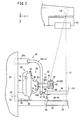
- a mammographic apparatus 10 which serves as a radiographic image capturing apparatus according to an embodiment of the present invention, basically includes an upstanding base 12, a vertical arm 16 fixed to the distal end of a horizontal swing shaft 14 (second rotational shaft) disposed substantially centrally on the base 12, a radiation source housing unit 26 accommodating a radiation source 24 therein for applying radiation 22 to a breast 20 (see FIG. 2 ) as a target object to be examined of an examinee 18, the radiation source housing unit 26 being fixed to an upper end of the arm 16, and an image capturing base 30 (holding member) fixed to a lower end of the arm 16 and housing therein a solid-state detector 28 (see FIG. 2 ) for detecting radiation 22 that has passed through the breast 20.
- the arm 16 has a vertical groove 32 defined in a side surface (front side) thereof, which faces toward the examinee 18 in the direction indicated by the arrow Y and extends in the directions indicated by the arrow Z.
- a compression plate support 34 is vertically movably supported on the arm 16 for displacement along the groove 32 in the directions indicated by the arrow Z.
- the compression plate support 34 includes a proximal end portion 34a inserted in the groove 32 and held in fitting engagement with a mount (not shown) in the groove 32.
- the proximal end portion 34a is disposed between the radiation source housing unit 26 and the image capturing base 30.
- the compression plate support 34 also includes two intermediate bars 34b, 34c extending from the free end of the proximal end portion 34a toward the image capturing base 30, and a joint 34d interconnecting distal ends of the intermediate bars 34b, 34c.
- the joint 34d is coupled to a rotational shaft 36 (first rotational shaft) extending in the direction indicated by the arrow Y (also referred to as a depth-wise direction of the breast 20).
- a compression plate 38 (compression member) for compressing and holding the breast 20 against the image capturing base 30 is pivotally supported on the distal end of the rotational shaft 36.
- the joint 34d houses therein a motor 47 (rotary actuator) for rotating the rotational shaft 36 about its axis. By energization of the motor 47, the motor 47 rotates the rotational shaft 36 about its axis, thereby turning the compression plate 38 about the axis of the rotational shaft 36.
- a display control panel 40 for displaying image capturing conditions including an image capturing region, etc., of the examinee 18, ID information of the examinee 18, etc., and for setting such items of information as necessary.
- the arm 16 to which the radiation source housing unit 26 and the image capturing base 30 are secured, is angularly moved about the swing shaft 14, an image capturing direction with respect to the breast 20 of the examinee 18 is adjusted.
- the radiation source housing unit 26 is coupled to the arm 16 by a hinge 42, so as to be angularly movable in the directions indicated by the arrow ⁇ independently of the image capturing base 30.
- Handles 44 are mounted on respective sides of the arm 16, which face away from each other along the directions indicated by the arrow ⁇ , i.e., the horizontal direction of the breast 20.
- the handles 44 are gripped by the examinee 18.
- the arm 16 has two holes 46 defined in the front side thereof near the image capturing base 30, one on each side of the groove 32.
- the mammographic apparatus 10 incorporates therein a biopsy apparatus 52 having a biopsy needle 50 (sampling needle) for sampling a sample tissue from a biopsy region 48 (test region) of the breast 20.
- the biopsy apparatus 52 includes a biopsy needle mount 54 with the biopsy needle 50 mounted thereon, and a biopsy needle moving mechanism 56 for moving the biopsy needle mount 54 in order to position the biopsy needle 50 at a desired position.
- the biopsy apparatus 52 is omitted from illustration.
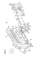
- the biopsy needle moving mechanism 56 includes a main unit 59 disposed on the image capturing base 30 with two base members 58 interposed therebetween.
- Two arms 60 are mounted on respective side surfaces of the main unit 59, which face away from each other along the directions indicated by the arrow X.
- the arms 60 extend toward the arm 16 and have respective rods 62 that fit into respective holes 46 provided in the arm 16.
- the main unit 59 which is disposed on the image capturing base 30 with the two base members 58 interposed therebetween and with the two rods 62 fitted into the respective holes 46, is fixed in position between the arm 16 and the intermediate bars 34b, 34c, such that the main unit 59 is disposed in facing relation to the examinee 18.
- the main unit 59 includes an upstanding rear member 64, which extends in the directions indicated by the arrow Z and is disposed near the arm 16, a front member 66 mounted on a front side of the rear member 64 (facing the examinee 18), a moving unit 68 mounted on a front side of the front member 66, and another moving unit 70 mounted on a front side of the moving unit 68.
- a knob 72 is disposed on a side surface of the main unit 59, at the boundary between the rear member 64 and the front member 66.
- Two knobs 74, 76 are disposed on a side surface of the moving unit 68.
- Three rods 78, 80, 82 are mounted on a front side of the moving unit 70 and extend along the directions indicated by the arrow Y.
- a flat holder 84 is mounted on distal ends of the rods 78, 80, 82.
- the rear member 64 comprises a thin member having a relatively large recess defined therein that faces toward the examinee 18.
- the front member 66 also is a thin member having a relatively large recess defined therein that faces toward the arm 16.
- the respective recesses jointly make up a relatively large closed space in the main unit 59, which accommodates a moving mechanism therein comprising machine elements (not shown) for moving the biopsy needle 50.
- the moving unit 68 is capable of being moved by the moving mechanism in directions indicated by the arrow Z with respect to the front member 66.
- the moving unit 70 is capable of being moved by the moving mechanism in directions indicated by the arrow X with respect to the moving unit 68.
- the holder 84 is movable in directions indicated by the arrow Y upon the rods 78, 80, 82 being moved by the moving mechanism in directions indicated by the arrow Y.
- Machine elements of the moving mechanism may be made up from gears, worm gears, racks, and pinions of a known nature for moving the various components of the main unit 59 referred to above in respective directions indicated by the arrows X, Y, Z.
- the knobs 72, 74, 76 are operatively coupled to the moving mechanism.
- rotational power from the knob 72 is transmitted to the moving mechanism, which then displaces the moving unit 68 in the directions indicated by the arrow Z.
- rotational power of the knob 74 is transmitted to the moving mechanism, which then displaces the moving unit 70 in the directions indicated by the arrow X.
- rotational power from the knob 76 is transmitted to the moving mechanism, which then displaces the rods 78, 80, 82 in the directions indicated by the arrow Y.
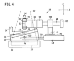
- An arm support 86 which is U-shaped as viewed in side elevation in FIG. 2 , is fixed to the holder 84.
- An arm 88 which extends in the directions indicated by the arrow X, has an end 90 pivotally supported on the arm support 86.
- the arm support 86 comprises a U-shaped component including a flat member attached to the holder 84, and a pair of upper and lower wings that project from respective upper and lower ends of the flat member toward the examinee 18.
- the end 90 of the arm 88 is substantially U-shaped and is held in contact with inner surfaces of the arm support 86.
- a vertical pivot pin 92 extends through the upper and lower wings of the arm support 86 and through the U-shaped end 90 of the arm 88, thereby joining the arm support 86 and the arm 88 to each other.
- the U-shaped end 90 of the arm 88 is angularly movable about the pivot pin 92.
- a knob 94 is disposed on the upper wing of the arm support 86 and extends therethrough so as to come into abutment against the end 90 of the arm 88.
- the knob 94 is externally threaded and held in threaded engagement with an internally threaded surface of the upper wing of the arm support 86. In a case where the doctor or radiological technician turns the knob 94 until the lower end of the knob 94 abuts against the end 90 of the arm 88, both the arm 88 and the end 90 of the arm 88 are secured in position angularly about the pivot pin 92.
- the arm 88 has another end 96, to which a rectangular rod 98 is fixed that extends in the directions indicated by the arrow X.
- the rod 98 has a distal end joined to an end block 102.
- a slider 106 is slidably supported on the rod 98 for sliding movement between the other end 96 and the end block 102.
- the slider 106 may be moved automatically by a motor-driven cylinder, or may be displaced manually by the doctor or radiological technician.
- the slider 106 is coupled to an attachment 120 in the form of a flat plate by a support member 118, which extends downwardly from the slider 106 toward the image capturing base 30.
- the biopsy needle mount 54 is attached to the attachment 120.
- the biopsy needle 50 includes a sampler 122 for attracting and sampling tissue, such as calcified tissue, from the biopsy region 48 of the breast 20.
- the biopsy needle moving mechanism 56 moves the moving unit 68 in the directions indicated by the arrow Z, moves the moving unit 70 in the directions indicated by the arrow X, and moves the rods 78, 80, 82 together with the holder 84 in the directions indicated by the arrow Y.
- the end 90 of the arm 88 is pivotally supported by the pivot pin 92, which extends through the arm support 86 that is fixed to the holder 84.
- the slider 106 is slidable in the directions indicated by the arrow X along the rod 98, which extends between and is joined to the other end 96 of the arm 88 and the end block 102.
- the biopsy needle mount 54, with the biopsy needle 50 mounted thereon, is connected to the slider 106 by the support member 118 and the attachment 120.
- the biopsy needle 50 is moved in respective directions indicated by the arrows X, Y, Z, and if the slider 106 is slidably displaced along the rod 98 between the other end 96 of the arm 88 and the end block 102, the biopsy needle 50 is moved in the directions indicated by the arrow X. If the end 90 of the arm 88 is angularly moved about the pivot pin 92, the biopsy needle 50 is moved angularly in the X-Y plane, i.e., a plane defined by the arrows X and Y.
- the compression plate 38 is tilted with respect to the image capturing base 30 along the directions indicated by the arrow X, i.e., along lateral or horizontal directions of the breast 20. If the breast 20 is compressed by the compression plate 38, which is tilted as described above, pressure applied to the breast 20 from the compression plate 38 and the image capturing base 30 is unevenly distributed along the directions indicated by the arrow X.
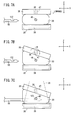
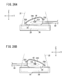
- FIGS. 6A through 9C certain components are schematically illustrated for the purpose of explaining characteristic functions of the present embodiment, i.e., functions for compressing the breast 20 with the compression plate 38, which is tilted with respect to the image capturing base 30.
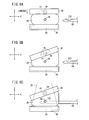
- FIGS. 6A through 7C show two examples in which the image capturing base 30 and the compression plate 38, which lie parallel to each other along the directions indicated by the arrow X, compress the breast 20 therebetween, and thereafter, the compression plate 38 is tilted relatively to the image capturing base 30 to compress the breast 20 while the compression plate 38 remains in a tilted condition.
- the compression plate 38 is tilted downward to the left with respect to the image capturing base 30 along the directions indicated by the arrow X, so as to compress the breast 20 while the compression plate 38 is in a tilted state.
- the image capturing base 30 and the compression plate 38 initially lie parallel to each other along the directions indicated by the arrow X with the breast 20 interposed therebetween. Then, as shown in FIG. 6A , the compression plate 38 is lowered toward the image capturing base 30, thereby compressing and holding the breast 20 on the image capturing base 30. At this time, since the image capturing base 30 and the compression plate 38 lie parallel to each other, pressure that is applied to the breast 20 from the compression plate 38 and the image capturing base 30 is uniformly distributed along the directions indicated by the arrow X.
- the motor 47 is energized to turn the rotational shaft 36 about its axis counterclockwise in a - ⁇ direction, as shown in FIG. 6B .
- the compression plate 38 also is turned in the - ⁇ direction and is tilted downward to the left in FIG. 6B with respect to the image capturing base 30.
- the breast 20 is compressed obliquely downward to the left by the tilted compression plate 38 and the image capturing base 30.
- pressure that is applied to the breast 20 from the compression plate 38 and the image capturing base 30 is relatively high at the left region of the breast 20, and is relatively low at the right region of the breast 20 along the directions indicated by the arrow X, and hence the pressure is unevenly distributed along the directions indicated by the arrow X.
- the biopsy needle 50 is inserted into the right region of the breast 20 along the leftward direction as indicated by the arrow X. Since the left region of the breast 20 is compressed firmly under a higher pressure by the compression plate 38 and the image capturing base 30, which are in close proximity to each other, even if a piercing force is applied to the breast 20 from the biopsy needle 50 while piercing the right region of the breast 20 along the leftward direction as indicated by the arrow X, the breast 20 is prevented from being unduly positionally displaced to the left in FIG. 6C .
- radiation 22 is applied to the breast 20 in order to acquire a radiographic image of the breast.
- radiation 22 may be applied to the breast 20 in order to acquire a radiographic image while the breast 20 is compressed by the compression plate 38 and the image capturing base 30, which lie parallel to each other, as shown in FIG. 6A . Radiation is not applied to the breast 20 while the compression plate 38 undergoes movement or is turned, or while the biopsy needle 50 undergoes movement.
- the compression plate 38 is tilted downward to the right with respect to the image capturing base 30 along the directions indicated by the arrow X, whereupon the compression plate 38 compresses the breast 20 while the compression plate 38 is in a tilted state.
- the compression plate 38 and the biopsy needle 50 move in patterns, which are a reversal of the movement of the compression plate 38 and the biopsy needle 50 shown in FIGS. 6A through 6C .
- the image capturing base 30 and the compression plate 38 initially lie parallel to each other along the directions indicated by the arrow X with the breast 20 interposed therebetween. Then, as shown in FIG. 7A , the compression plate 38 is lowered toward the image capturing base 30, thereby compressing and holding the breast 20 on the image capturing base 30. Then, the motor 47 is energized to turn the rotational shaft 36 about its axis clockwise in a + ⁇ direction, as shown in FIG. 7B . Thus, the compression plate 38 is tilted downward to the right in FIG. 7B with respect to the image capturing base 30. As a result, the breast 20 is compressed obliquely downward to the right by the tilted compression plate 38 and the image capturing base 30.
- the breast 20 Since the right region of the breast 20 is compressed firmly under higher pressure by the compression plate 38 and the image capturing base 30, which are in close proximity to each other, even if a piercing force is applied to the breast 20 from the biopsy needle 50, which pierces the right region of the breast 20 along the leftward direction indicated by the arrow X, the breast 20 is prevented from being unduly positionally displaced to the right in FIG. 7C .
- FIGS. 8A through 9C show two examples, which differ from the two examples shown in FIGS. 6A through 7C , in that the compression plate 38, which is spaced from the breast 20 and the image capturing base 30, is tilted with respect to the image capturing base 2 along the directions indicated by the arrow X, whereupon the breast 20 is compressed obliquely by the tilted compression plate 38 and the image capturing base 30.
- the compression plate 38 is tilted downward to the left with respect to the image capturing base 30 along the directions indicated by the arrow X.
- the compression plate 38 compresses the breast 20 while the compression plate 38 is in a tilted state.
- the motor 47 is energized to turn the rotational shaft 36 about its axis counterclockwise in the - ⁇ direction.
- the compression plate 38 is also turned in the - ⁇ direction, and tilted downward to the left in FIG. 8B with respect to the image capturing base 30.
- the tilted compression plate 38 is lowered toward the image capturing base 30, thereby compressing and holding the breast 20 on the image capturing base 30.
- the breast 20 is compressed obliquely downward to the left in FIG. 8B by the tilted compression plate 38 and the image capturing base 30.
- the breast 20 Since the left region of the breast 20 is compressed firmly under the higher pressure by the compression plate 38 and the image capturing base 30, which are brought into close proximity with each other, even if a piercing force is applied to the breast 20 from the biopsy needle 50, which pierces the right region of the breast 20 along the leftward direction indicated by the arrow X, the breast 20 is prevented from being unduly positionally displaced to the left in FIG. 8C .
- the compression plate 38 is tilted downward to the right with respect to the image capturing base 30 along the directions indicated by the arrow X, and the compression plate 38 compresses the breast 20 while the compression plate 38 is tilted.
- the compression plate 38 and the biopsy needle 50 move in patterns, which are a reversal of the movement of the compression plate 38 and the biopsy needle 50 shown in FIGS. 8A through 8C .
- the motor 47 is energized to turn the rotational shaft 36 about its axis counterclockwise in the + ⁇ direction, thereby tilting the compression plate 38 downward to the right in FIG. 9A with respect to the image capturing base 30.
- the tilted compression plate 38 is lowered toward the image capturing base 30, thereby compressing and holding the breast 20 on the image capturing base 30.
- the breast 20 is compressed obliquely downward to the right in FIG. 9B by the tilted compression plate 38 and the image capturing base 30.
- the breast 20 Since the right region of the breast 20 is strongly compressed under the higher pressure by the compression plate 38 and the image capturing base 30, which are brought into close proximity with each other, even if the piercing force is applied to the breast 20 from the biopsy needle 50, which pierces the left region of the breast 20 along the leftward direction indicated by the arrow X, the breast 20 is prevented from being unduly positionally displaced to the right in FIG. 9C .
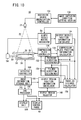
- FIG. 10 shows in block form the mammographic apparatus 10 shown in FIG. 1 .
- the mammographic apparatus 10 includes an image capturing condition setting section 130, a radiation source energization controller 132, a biopsy needle position information calculator 134, a compression plate controller 136, a compression plate position information calculator 138, a detector controller 140, an image information storage unit 142, a CAD (computer aided diagnosis) processor 144, a display unit 146, a biopsy region selector 148, a biopsy region position information calculator 150, a piercing direction determiner 152, a tilted direction determiner 154, and a traveled distance calculator 156.
- CAD computer aided diagnosis
- the image capturing condition setting section 130 sets image capturing conditions including a tube current and a tube voltage of the radiation source 24, an irradiation dose and an irradiation time for the radiation 22, an image capturing method, and an image capturing sequence, etc.
- the radiation source energization controller 132 controls energization of the radiation source 24 according to the image capturing conditions.
- the biopsy needle moving mechanism 56 outputs information concerning the distance that the biopsy needle 50 has moved or turned, e.g., information concerning the angular displacement of gears or the like of the non-illustrated moving mechanism, to the biopsy needle position information calculator 134. Based on such information from the biopsy needle moving mechanism 56, the biopsy needle position information calculator 134 calculates the three-dimensional position (present position) of the tip end of the biopsy needle 50.
- the compression plate controller 136 moves the compression plate support 34 and the compression plate 38 in directions indicated by the arrow Z and/or energizes the motor 47 in order to turn the compression plate 38 about the rotational shaft 36 in the + ⁇ direction or the - ⁇ direction.
- the compression plate position information calculator 138 calculates the position of the compression plate 38, which has been moved and/or turned by the compression plate controller 136 with respect to the image capturing base 30. Since the compression plate 38 compresses and holds the breast 20 with respect to the image capturing base 30, the position information of the compression plate 38 represents the thickness of the breast 20 as the breast 20 is compressed, and the tilt angle at which the compression plate 38 is tilted with respect to the image capturing base 30.
- the detector controller 140 controls the solid-state detector 28 to acquire a radiographic image of the breast 20, which is converted from the radiation 22, and stores the acquired radiographic image in the image information storage unit 142.
- the CAD processor 144 processes the radiographic image stored in the image information storage unit 142, and displays the processed radiographic image on the display unit 146 and the display control panel 40.
- the mammographic apparatus 10 performs either a scout image capturing process, in which the radiation source 24, which is disposed on the vertical axis (i.e., along the directions indicated by the arrow Z) of the solid-state detector 28, applies radiation 22 to the breast 20, or a stereographic image capturing process, in which the radiation source 24, which is disposed at certain angles after the radiation source housing unit 26 has been turned along the directions indicated by the arrow ⁇ , applies radiation 22 to the breast 20.
- the solid-state detector 28 detects radiation 22 that has passed through the breast 20 in the scout image capturing process or the stereographic image capturing process, and converts the detected radiation 22 into one or more radiographic images.
- the biopsy region selector 148 comprises a pointing device such as a mouse or the like.
- the doctor or radiological technician in charge who has viewed the displayed contents (e.g., two radiographic images produced by the stereographic image capturing process) on the display unit 146 and/or the display control panel 40 can select one of a plurality of biopsy regions 48 in the displayed two radiographic images from which tissue is to be removed, using the pointing device as the biopsy region selector 148. More specifically, the doctor or radiological technician selects a biopsy region 48 in one of the two radiographic images, and also selects a corresponding biopsy region 48 in the other of the two radiographic images.
- the biopsy region position information calculator 150 calculates the three-dimensional position of the biopsy region 48 based on positions of the biopsy region 48 that have been selected in the two radiographic images by the biopsy region selector 148.
- the three-dimensional position of the biopsy region 48 can be calculated according to a known three-dimensional position calculating scheme for stereographic image capturing processes.
- the piercing direction determiner 152 judges the piercing direction in which the biopsy needle 50 pierces the breast 20 based on the three-dimensional position of the tip end of the biopsy needle 50, which has been calculated by the biopsy needle position information calculator 134, the position of the compression plate 38, which has been calculated by the compression plate position information calculator 138, and/or the three-dimensional position of the biopsy region 48, which has been calculated by the biopsy region position information calculator 150.
- the piercing direction determiner 152 specifies the piercing direction in which the biopsy needle 50 pierces the breast 20, using the three-dimensional position of the tip end of the biopsy needle 50 and the position of the breast 20, based on the position of the compression plate 38.
- the piercing direction determiner 152 can also specify the piercing direction in which the biopsy needle 50 pierces the breast 20 based on the three-dimensional position of the tip end of the biopsy needle 50 and the three-dimensional position of the biopsy region 48, which has been calculated by the biopsy region position information calculator 150.
- the piercing direction determiner 152 can also specify the piercing direction in which the biopsy needle 50 pierces the breast 20 based on the three-dimensional position of the tip end of the biopsy needle 50, the position of the compression plate 38, and the three-dimensional position of the biopsy region 48.
- the tilted direction determiner 154 determines the tilted direction in which the compression plate 38 is tilted with respect to the image capturing base 30, based on the piercing direction in which the biopsy needle 50 pierces the breast 20, as determined by the piercing direction determiner 152, and the position of the compression plate 38 with respect to the image capturing base 30.
- the tilted direction determiner 154 decides that the compression plate 38 should be tilted downward to the left with respect to the image capturing base 30, whereas, if the biopsy needle 50 pierces the left region of the breast 20 (see FIGS. 7A and 9A ), the tilted direction determiner 154 decides that the compression plate 38 should be tilted downward to the right with respect to the image capturing base 30.
- the compression plate controller 136 energizes the motor 47 according to the tilted direction, as determined by the tilted direction determiner 154, so as to tilt the compression plate 38 in the determined tilting direction.
- the traveled distance calculator 156 calculates the distance by which the biopsy needle 50 moves with respect to the biopsy region 48, based on the three-dimensional position of the biopsy region 48, which has been calculated by the biopsy region position information calculator 150, the three-dimensional position of the tip end of the biopsy needle 50, which has been calculated by the biopsy needle position information calculator 134, the position of the compression plate 38, which has been calculated by the compression plate position information calculator 138 (the thickness of the breast 20), the piercing direction of the biopsy needle 50, which has been determined by the piercing direction determiner 152, and the tilted direction of the compression plate 38, which has been determined by the tilted direction determiner 154.
- the biopsy needle moving mechanism 56 moves the biopsy needle 50, in order to enable a tissue sample to be removed from the biopsy region 48 according to a lateral approach biopsy procedure.
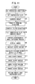
- the mammographic apparatus 10 is basically constructed as described above. Next, operations of the mammographic apparatus 10 will be described below with reference to the flowchart shown in FIG. 11 , as well as with reference to FIGS. 1 through 10 .
- the mammographic apparatus 10 performs a stereographic image capturing process after compressing the breast 20 between the image capturing base 30 and the compression plate 38, and thereafter, the mammographic apparatus 10 performs a lateral approach biopsy procedure on the breast 20 based on radiographic images generated by the stereographic image capturing process.
- a lateral approach biopsy procedure performed on the breast 20 after the breast 20 has been compressed and held in position will be described, first with reference to the examples shown in FIGS. 6A through 7C , and then with reference to the examples shown in FIGS. 8A through 9C .
- step S1 shown in FIG. 11 the image capturing condition setting section 130 (see FIG. 10 ) sets image capturing conditions including a tube current and a tube voltage of the radiation source 24, an irradiation dose and an irradiation time for the radiation 22, an image capturing method, and an image capturing sequence, etc., depending on characteristics of the breast 20.
- the image capturing conditions are set in the radiation source energization controller 132.
- step S2 the doctor or radiological technician inserts the rods 62 respectively into the holes 46 (see FIGS. 1 and 2 ), so as to place the biopsy apparatus 52 (see FIG. 3 ) including the main unit 59 in a given position on the image capturing base 30, and then inserts the proximal end portion 34a of the compression plate support 34 into the groove 32.
- step S3 the breast 20 of the examinee 18 is compressed by the image capturing base 30 and the compression plate 38. More specifically, the breast 20 is placed in a given position (i.e., at a position facing the compression plate 38) on the image capturing base 30, and then the compression plate controller 136 moves the compression plate 38, which lies parallel to the image capturing base 30, toward the image capturing base 30 in the downward direction indicated by the arrow Z, thereby compressing the breast 20. The breast 20 is compressed by the image capturing base 30 and the compression plate 38 under a uniform pressure along the directions indicated by the arrow X.
- the compression plate position information calculator 138 calculates the position information of the compression plate 38 with respect to the image capturing base 30.
- step S4 the biopsy needle moving mechanism 56 outputs information concerning the distance that the biopsy needle 50 is to move or turn to the biopsy needle position information calculator 134.
- the biopsy needle position information calculator 134 calculates the three-dimensional position of the tip end of the biopsy needle 50.
- the piercing direction determiner 152 judges the piercing direction in which the biopsy needle 50 pierces the breast 20 based on the three-dimensional position of the tip end of the biopsy needle 50, which has been calculated by the biopsy needle position information calculator 134, and the position of the compression plate 38, which has been calculated by the compression plate position information calculator 138.
- step S5 the tilted direction determiner 154 determines the tilted direction in which the compression plate 38 is tilted with respect to the image capturing base 30 based on the piercing direction in which the biopsy needle 50 pierces the breast 20, which has been determined by the piercing direction determiner 152, and the position of the compression plate 38, which has been calculated by the compression plate position information calculator 138.
- step S6 the compression plate controller 136 energizes the motor 47 in accordance with the tilted direction, which was determined by the tilted direction determiner 154.
- the motor 47 which is energized, turns the rotational shaft 36 about its axis, thereby tilting the compression plate 38 with respect to the image capturing base 30 in the tilted direction along the directions indicated by the arrow X, whereupon the breast 20 is compressed obliquely downward by the tilted compression plate 38 and the image capturing base 30. Consequently, pressure that is applied to the breast 20 from the compression plate 38 and the image capturing base 30 is distributed unevenly along the directions indicated by the arrow X.
- the breast 20 which is compressed obliquely downward, is ready to be imaged in the stereographic image capturing process.
- step S7 the mammographic apparatus 10 energizes the radiation source 24 in order to perform a stereographic image capturing process on the breast 20. More specifically, the radiation source housing unit 26 is turned about the hinge 42 (see FIG. 1 ) in the ⁇ directions, so as to place the radiation source 24 successively at two different angular positions. In a case where the radiation source 24 has been placed successively at each of the two angular positions, the radiation source 24 emits radiation 22, which passes through the breast 20 and is applied to the solid-state detector 28 in the image capturing base 30. The solid-state detector 28 detects two radiographic images of the breast 20 based on radiation 22 that is transmitted through the breast 20.
- the detector controller 140 controls the solid-state detector 28 so as to acquire two radiographic images of the breast 20, and then stores the acquired two radiographic images in the image information storage unit 142.
- step S8 the CAD processor 144 processes the two radiographic images, which are stored in the image information storage unit 142, and displays the processed radiographic images on the display unit 146 and the display control panel 40.
- step S9 the doctor or radiological technician selects one of a plurality of biopsy regions 48 in the two radiographic images displayed on the display unit 146 and/or the display control panel 40, from which a tissue sample is to be removed, using the biopsy region selector 148, which is a pointing device such as a mouse.
- the biopsy region selector 148 which is a pointing device such as a mouse.
- the biopsy region position information calculator 150 calculates the three-dimensional position of the selected biopsy region 48 based on the position of the selected biopsy region 48 in the two radiographic images.
- the traveled distance calculator 156 calculates the distance by which the biopsy needle 50 moves with respect to the biopsy region 48, based on the three-dimensional position of the biopsy region 48, which has been calculated by the biopsy region position information calculator 150, the three-dimensional position of the tip end of the biopsy needle 50, which has been calculated by the biopsy needle position information calculator 134, the position of the compression plate 38, which has been calculated by the compression plate position information calculator 138, the piercing direction of the biopsy needle 50, which has been determined by the piercing direction determiner 152, and the tilted direction of the compression plate 38, which has been determined by the tilted direction determiner 154.
- the biopsy needle moving mechanism 56 moves the biopsy needle 50 based on the distance, which has been calculated by the traveled distance calculator 156, by which the biopsy needle 50 moves with respect to the biopsy region 48.
- the biopsy needle moving mechanism 56 causes the main unit 59 thereof to control movement of the biopsy needle 50 in the directions indicated by the arrows X, Y, Z, so as to position the biopsy needle 50 in a position that faces toward the biopsy region 48, i.e., in a position facing toward the biopsy region 48 along the directions indicated by the arrow X.
- the slider 106 is moved along the rod 98 in the directions indicated by the arrow X in order to move the biopsy needle 50 toward a side region of the breast 20.
- the biopsy needle 50 pierces the side region of the breast 20.
- step S13 the biopsy needle 50 starts a suction process to extract a sample tissue from the biopsy region 48 through the sampler 122.
- the biopsy needle moving mechanism 56 retracts the biopsy needle 50 until the biopsy needle 50 is pulled out from the breast 20, whereupon the lateral approach biopsy procedure is brought to an end.
- step S15 the compression plate 38 is elevated to release the breast 20 from the compressed state.
- the mammographic apparatus 10 operates as described above in the examples shown in FIGS. 6A through 7C .
- the mammographic apparatus 10 operates in the examples shown in FIGS. 8A through 9C in the following manner. After step S2, step S3 is skipped, and steps S4, S5 are carried out.
- step S6 the compression plate controller 136 energizes the motor 47 according to the tilted direction decided by the tilted direction determiner 154.
- the motor 47 which is energized, turns the rotational shaft 36 about its axis, thereby tilting the compression plate 38 with respect to the image capturing base 30 along the directions indicated by the arrow X, while the compression plate 38 is spaced away from the image capturing base 30.
- the breast 20 is compressed by the tilted compression plate 38 and the image capturing base 30. More specifically, after the breast 20 has been placed in a given position on the image capturing base 30, the compression plate controller 136 moves the compression plate 38 downwardly toward the image capturing base 30 in the direction indicated by the arrow Z, whereupon the breast 20 is compressed obliquely downward by the tilted compression plate 38 and the image capturing base 30. Consequently, pressure that is applied to the breast 20 from the compression plate 38 and the image capturing base 30 is distributed unevenly along the directions indicated by the arrow X.
- steps S7 through S15 are carried out successively as described above.
- the compression plate 38 is tilted with respect to the image capturing base 30 along the directions indicated by the arrow X, i.e., along lateral or horizontal directions of the breast 20.
- the upper surface of the image capturing base 30 and the lower surface of the compression plate 38, each of which serves as a surface for compressing the breast 20 are tilted with respect to the breast 20.
- pressure applied to the breast 20 from the image capturing base 30 and the compression plate 38 is distributed unevenly along the directions indicated by the arrow X.
- the biopsy needle 50 is accurately inserted into the breast 20 with respect to the biopsy region 48, so as to enable the biopsy needle 50 to reliably and efficiently remove a sample tissue from the biopsy region 48.
- the compression plate 38 compresses the breast 20 while the compression plate 38 is tilted along lateral or horizontal directions, i.e., in the directions indicated by the arrow X, with respect to the image capturing base 30, pressure that is applied to the breast 20 from the image capturing base 30 and the compression plate 38 is distributed unevenly along the directions indicated by the arrow X.
- the compressed breast 20 is prevented from being unduly positionally displaced during the lateral approach biopsy procedure.
- Preventing the compressed breast 20 from being unduly positionally displaced is effective to avoid compressing the breast 20 under an excessively high pressure, so that any undue stresses on the examinee 18 and the breast 20 of the examinee 18 can be reduced.
- the tilted direction determiner 154 determines the tilted direction in which the compression plate 38 is tilted with respect to the image capturing base 30, based on the piercing direction in which the biopsy needle 50 pieces the breast 20, as determined by the piercing direction determiner 152, the breast 20 is efficiently prevented from being unduly positionally displaced when the breast 20 is pierced by the biopsy needle 50.
- the tilted direction determiner 154 determines the tilted direction in which the compression plate 38 is tilted with respect to the image capturing base 30, such that the distance between the image capturing base 30 and the compression plate 38 becomes progressively smaller from one side to the other side of the breast 20.
- the pressure under which the breast 20 is compressed is relatively low on one side of the breast 20 where the compression plate 38 and the image capturing base 30 are spaced widely from each other, whereas the pressure under which the breast 20 is compressed is relatively high on the other side of the breast 20 where the compression plate 38 and the image capturing base 30 are in close proximity to each other.
- the one side of the breast 20 is pierced by the biopsy needle 50 along one of the directions indicated by the arrow X
- the other side of the breast 20 is compressed or held down in position under a relatively high pressure, the breast 20 is reliably prevented from being unduly positionally displaced toward the other side along the one direction indicated by the arrow X.
- the piercing direction determiner 152 automatically judges the piercing direction in which the biopsy needle 50 pierces the breast 20 based on the three-dimensional position (present position) of the biopsy needle 50, which has been calculated by the biopsy needle position information calculator 134.
- the tilted direction determiner 154 can easily and accurately determine the tilted direction in which the compression plate 38 is tilted with respect to the image capturing base 30, based on the piercing direction as determined by the piercing direction determiner 152.
- the motor 47 rotates the rotational shaft 36, which extends in the directions indicated by the arrow Y, i.e., the depth-wise direction of the breast 20, to turn the compression plate 38, thereby easily tilting the compression plate 38 with respect to the image capturing base 30.
- the mammographic apparatus 10 may tilt the compression plate 38 with respect to the image capturing base 30 after the breast 20 has been compressed by the compression plate 38 and the image capturing base 30, or alternatively, may compress the breast 20 between the compression plate 38 and the image capturing base 30 after the compression plate 38 has been tilted with respect to the image capturing base 30. In either case, the breast 20 is compressed and held under an uneven pressure along the directions indicated by the arrow X.
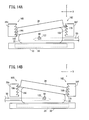
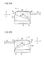
- FIGS. 12 through 14B show a first modification, which differs from the above embodiment ( FIGS. 1 through 11 ), in that distal-end portions 34e, 34f extend toward the examinee 18 respectively from distal ends of the intermediate bars 34b, 34c of the compression plate support 34, and the compression plate 38 is tiltably mounted on the distal-end portions 34e, 34f.
- tilted state maintaining mechanisms 160, 162 which serve to tilt the compression plate 38 with respect to the image capturing base 30, and to hold or maintain the compression plate 38 tilted with respect to the image capturing base 30, are disposed between side surfaces of the distal-end portions 34e, 34f, which face toward the compression plate 38, and side surfaces of the compression plate 38, which face toward the distal-end portions 34e, 34f.
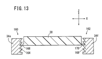
- the tilted state maintaining mechanisms 160, 162 are analogous to a lock structure of a band for fastening a plurality of cables (cable tie). As shown in FIG. 13 , the tilted state maintaining mechanisms 160, 162 have respective sets of engaging grooves 164, 168 disposed on respective side surfaces of the distal-end portions 34e, 34f, which face toward the compression plate 38 and are arrayed along the directions indicated by the arrow Z, and respective fingers 166, 170 disposed on respective side surfaces of the compression plate 38 for engagement in selected ones of the engaging grooves 164, 168.
- Each of the engaging grooves 164, 168 is defined by a tapered surface, which is inclined obliquely downward, and a horizontal surface that extends in the directions indicated by the arrow X.
- the fingers 166, 170 can be held on the respective horizontal surfaces.
- the fingers 166, 170 have a length, which is large enough to be held on the horizontal surfaces of the engaging grooves 164, 168, and a thickness, which is sufficiently smaller than the compression plate 38, so as to enable the fingers 166, 170 to be flexible.
- the fingers 166, 170 engage within the horizontal surfaces of certain engaging grooves 164, 168, which are at the same height.
- the doctor or radiological technician presses the left side of the compression plate 38 toward the image capturing base 30.
- a distal end of the flexible finger 166 is curved upwardly along the tapered surface toward the compression plate 38 about the proximal end thereof, which is joined to the compression plate 38.
- the finger 166 then is released out of engagement with the engaging groove 164, thereby allowing the left side of the compression plate 38 to descend toward the image capturing base 30 under the pressing force.
- the finger 166 is taken out from the engaging groove 164 and is inserted into the next lower engaging groove 164. Immediately thereafter, the finger 166 snaps out of the curved state, whereby the distal end of the finger 166 moves along the tapered surface of the next lower engaging groove 164 about the proximal end thereof, until the finger 166 hits against the horizontal surface of the next lower engaging groove 164. Upon the finger 166 hitting against the horizontal surface of the next lower engaging groove 164, the finger 166 is held in the next lower engaging groove 164. As a result, the compression plate 38 is tilted downward to the left in FIG. 14A , and is maintained in such a tilted state.
- FIG. 14A shows the finger 166, which engages in the lowermost engaging groove 164 of the distal-end portion 34e.
- the doctor or radiological technician continuously presses the left side of the compression plate 38, so as to angularly displace the compression plate 38 from the horizontal state shown in FIG. 13 to the tilted state shown in FIG. 14A .
- FIG. 14B shows the finger 170, which engages in the lowermost engaging groove 168 of the distal-end portion 34f.
- the doctor or radiological technician continuously presses the right side of the compression plate 38, so as to angularly displace the compression plate 38 from the horizontal state shown in FIG. 13 to the tilted state shown in FIG. 14B .
- the compression plate 38 can be tilted with respect to the image capturing base 30, the advantages of the above embodiment can easily be achieved. Furthermore, since the compression plate 38 can be maintained in a tilted state by the tilted state maintaining mechanisms 160, 162, the breast 20 can reliably be kept in a compressed state.
- the doctor or radiological technician presses the right or left side of the compression plate 38 from above in order to tilt the compression plate 38 downward to the right or left with respect to the image capturing base 30.
- a pressing mechanism (not shown) may also be used to automatically press the compression plate 38.
- the tilted direction which is determined by the tilted direction determiner 154, preferably is displayed on the display unit 146 and/or the display control panel 40.
- the doctor or radiological technician can easily recognize the region (right or left side) of the compression plate 38 that is to be pressed, and hence can easily and accurately carry out the process of tilting the compression plate 38.
- Each of the engaging grooves 164, 168 is defined by a tapered surface, which extends from the horizontal surface upwardly toward the side surface of the compression plate 38. Therefore, although the fingers 166, 170 can be lowered toward the image capturing base 30, the fingers 166, 170 are prevented from moving upwardly by the tapered surfaces.
- the doctor or radiological technician may use a pin (not shown) in order to curve the tip ends of the fingers 166, 170 toward the compression plate 38, whereupon the compression plate 38 can be moved to a desired height.
- FIGS. 15 through 17B show a second modification, which differs from the above embodiment ( FIGS. 1 through 11 ) and the first modification ( FIGS. 12 through 14B ), in that the compression plate 38 is tiltably mounted on the joint 34d by tilted state maintaining mechanisms 180, 182, which are disposed between the joint 34d of the compression plate support 34 and a side surface of the compression plate 38 that faces toward the joint 34d.
- a side surface of the joint 34d which faces toward the compression plate 38, i.e., which confronts the chest wall 124 of the examinee 18, has two holes 184, 194 defined therein for receiving respective arms 188, 198 that extend respectively from left and right sides of the compression plate 38 toward the joint 34d.
- the holes 184, 194 include respective sets of engaging grooves 186, 196 provided in respective outer side surfaces that partially define the holes 184, 194, and which are arrayed along the directions indicated by the arrow Z.
- the arms 188, 198 have respective fingers 190, 200, which are engageable in selected ones of the engaging grooves 186, 196.
- the fingers 190, 200 and the engaging grooves 186, 196 jointly make up the tilted state maintaining mechanisms 180, 182, respectively.
- the tilted state maintaining mechanisms 180, 182 possess substantially the same functions as the tilted state maintaining mechanisms 160, 162 according to the first modification.
- each of the engaging grooves 186, 196 is defined by a tapered surface, which is inclined obliquely downward, and a horizontal surface extending in the directions indicated by the arrow X, such that the fingers 190, 200 are capable of being held on the respective horizontal surfaces.
- the fingers 190, 200 have a length large enough to be held on the horizontal surfaces of the engaging grooves 186, 196, and a thickness that is sufficiently smaller than the arms 188, 198 so as to enable the fingers 190, 200 to be flexible.
- the arms 188, 198 are inserted into the respective holes 184, 194, whereupon the fingers 190, 200 come into engagement with the horizontal surfaces of the engaging grooves 186, 196, which are at the same height, as shown in FIG. 16 .
- the compression plate 38 and the joint 34d have retaining mechanisms (not shown) for retaining the arms 188, 198 in the holes 184, 194, and for preventing removal thereof in a case where the arms 188, 198 have been inserted into the holes 184, 194 to install the compression plate 38 on the compression plate support 34.
- the doctor or radiological technician presses the left side of the compression plate 38 toward the image capturing base 30.
- a distal end of the flexible finger 190 is curved upwardly along the tapered surface toward the compression plate 38 about the proximal end thereof, which is joined to the arm 188 of the compression plate 38.
- the finger 190 is released from engagement with the engaging groove 186, thereby allowing the left side of the compression plate 38 to descend toward the image capturing base 30 under the pressing force.
- the finger 190 is taken out from the engaging groove 186 and is placed in the next lower engaging groove 186.
- the finger 190 snaps out of the curved state, whereupon the distal end of the finger 190 moves along the tapered surface of the next lower engaging groove 186 about the proximal end thereof, until the finger 190 comes into abutment against the horizontal surface of the next lower engaging groove 186.
- the finger 190 is held in the next lower engaging groove 186.
- the compression plate 38 is tilted downward to the left in FIG. 17A , and is maintained in the tilted state.
- the doctor or radiological technician may continuously press the left side of the compression plate 38 so as to angularly displace the compression plate 38 from the horizontal state shown in FIG. 16 to the tilted state shown in FIG. 17A .
- FIG. 17B shows the finger 200, which engages in the lowermost engaging groove 196 of the hole 194.
- the doctor or radiological technician continuously presses the right side of the compression plate 38, so as to angularly displace the compression plate 38 from the horizontal state shown in FIG. 16 to the tilted state shown in FIG. 17B .
- the advantages of the above embodiment and the first modification can easily be achieved, because the compression plate 38 is capable of being tilted with respect to the image capturing base 30.
- pressing mechanisms (not shown) may be used to automatically press the compression plate 38.
- the tilted direction which is determined by the tilted direction determiner 154, may be displayed on the display unit 146 and/or the display control panel 40, and the doctor or radiological technician may use a pin (not shown) in order to move the compression plate 38 to a desired height.
- FIGS. 18A and 18B show a third modification, which differs from the above embodiment ( FIGS. 1 through 11 ) and the first and second modifications ( FIGS. 12 through 17B ), in that the compression plate 38 is coupled to the compression plate support 34 by a shaft 210.
- the biopsy apparatus is free of the rotational shaft 36 and the motor 47.
- the compression plate 38 is coupled to the compression plate support 34 by the shaft 210, while the compression plate 38 is tilted downward to the left or right along the directions indicated by the arrow X with respect to the image capturing base 30.
- the third modification offers the same advantages as the above embodiment, because the breast 20 is compressed and held by the tilted compression plate 38 and the image capturing base 30.
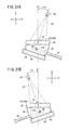
- FIGS. 19A and 19B show a fourth modification, which differs from the third modification ( FIGS. 18A and 18B ), in that a lower surface 212 of the compression plate 38 is constructed as a slanted surface, which is inclined with respect to the image capturing base 30. If the compression plate 38 is lowered toward the image capturing base 30, the breast 20 is obliquely compressed and held by the upper surface of the image capturing base 30 and the slanted lower surface 212 of the compression plate 38, which is tilted with respect to the image capturing base 30.
- the lower surface 212 of the compression plate 38 is constructed as a slanted surface, which is inclined with respect to the image capturing base 30, thereby keeping the compression plate 38 tilted with respect to the upper surface of the image capturing base 30. Therefore, simply by the compression plate 38 being displaced toward the image capturing base 30, the breast 20 is compressed and held under an uneven pressure along the directions indicated by the arrow X. As a result, the fourth modification offers the same advantages as the above embodiment and the first through third modifications.
- FIGS. 20A and 20B show a fifth modification, which differs from the fourth modification ( FIGS. 19A and 19B ), in that the compression plate 38 has a lower surface 214 constructed as a stepped slanted surface.
- the compression plate 38 has a lower surface 214 constructed as a stepped slanted surface.
- the lower surface 214 of the compression plate 38 is constructed as a slanted surface inclined with respect to the image capturing base 30, simply by the compression plate 38 being displaced toward the image capturing base 30, the breast 20 is compressed and held under an uneven pressure along the directions indicated by the arrow X.
- FIGS. 21A and 21B show a sixth modification, which differs from the above embodiment ( FIGS. 1 through 11 ) as well as the first through fifth modifications ( FIGS. 12 through 20B ), in that the arm 16 is turned about the swing shaft 14 in order to tilt the radiation source housing unit 26, which houses the radiation source 24 therein, and the image capturing base 30 with respect to the compression plate 38.
- the compression plate 38 is tiltably coupled to the compression plate support 34 by the rotational shaft 36, or alternatively, the compression plate 38 is coupled to the compression plate support 34 by the shaft 210 while the compression plate 38 is tilted.
- the motor 47 is energized to turn the rotational shaft 36, so as to keep the compression plate 38 substantially horizontal along the directions indicated by the arrow X. Therefore, the image capturing base 30 is tilted with respect to the compression plate 38.
- the compression plate 38 is coupled to the compression plate support 34 by the shaft 210 while the compression plate 38 is tilted, then in accordance with the tilted direction determined by the tilted direction determiner 154, the arm 16 is turned about the swing shaft 14 in order to turn the radiation source 24 and the image capturing base 30 through an angle of - ⁇ or + ⁇ . At this time, the compression plate 38 lies substantially horizontally along the directions indicated by the arrow X, and therefore, the image capturing base 30 is tilted with respect to the compression plate 38.
- the sixth modification offers the same advantages as the above embodiment and the first through fifth modifications.
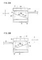
- FIGS. 22A and 22B show a seventh modification, which differs from the above embodiment ( FIGS. 1 through 11 ) and the first through sixth modifications ( FIGS. 12 through 21B ), in that a spacer 220 (first spacer) is disposed on a side surface of the compression plate 38 to face toward the breast 20, and has a lower surface 222 constructed as a slanted surface, which is inclined with respect to the image capturing base 30.
- a spacer 220 first spacer
- the breast 20 is compressed obliquely and held between the upper surface of the image capturing base 30 and the slanted lower surface 222 of the spacer 220.
- the lower surface 222 of the spacer 220 is constructed as a slanted surface, which is inclined with respect to the image capturing base 30, thereby keeping the spacer 220 tilted with respect to the upper surface of the image capturing base 30. Therefore, simply by displacing the compression plate 38 and the spacer 220 toward the image capturing base 30, the breast 20 is compressed and held under an uneven pressure along the directions indicated by the arrow X. As a result, the seventh modification offers the same advantages as the above embodiment and the first through fifth modifications.
- FIGS. 23A and 23B show an eighth modification, which differs from the seventh modification ( FIGS. 22A and 22B ), in that a spacer 230 (second spacer) is disposed on an upper surface of the image capturing base 30 that faces toward the breast 20.
- the spacer 230 has an upper surface 232 constructed as a slanted surface, which is inclined with respect to the compression plate 38.
- the compression plate 38 is lowered toward the spacer 230 and the image capturing base 30, the breast 20 is obliquely compressed and held by the upper surface 232 of the spacer 230 and the compression plate 38.
- the upper surface 232 of the spacer 230 is constructed as a slanted surface, which is inclined with respect to the compression plate 38, thereby keeping the spacer 230 tilted with respect to the compression plate 38. Therefore, simply by displacing the compression plate 38 toward the spacer 230 and the image capturing base 30, the breast 20 is compressed and held under an uneven pressure along the directions indicated by the arrow X. As a result, the eighth modification offers the same advantages as the above embodiment and the first through seventh modifications.
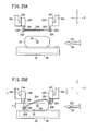
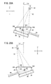
- FIGS. 24 through 26B show a ninth modification, which differs from the above embodiment ( FIGS. 1 through 11 ) and the first through eighth modifications ( FIGS. 12 through 23B ), in that motor-driven cylinders 240, 242 (first and second rod movement controllers) are mounted respectively on the distal-end portions 34e, 34f of the compression plate support 34. Respective rods 246, 252 of the motor-driven cylinders 240, 242 are moved toward and away from the image capturing base 30.
- the rods 246, 252 displace a flexible compression sheet 244 (compression member), which is made of resin, toward the image capturing base 30.
- Tubular members 248, 254 are fixed to distal ends of the respective rods 246, 252 of the motor-driven cylinders 240, 242, and rods 250, 256 (first and second rods) extend from the respective tubular members 248, 254 toward the examinee 18. Lateral opposite ends of the compression sheet 244 are spaced from each other along the directions indicated by the arrow X, and are supported respectively by the rods 250, 256.
- the respective rods 246, 252 of the motor-driven cylinders 240, 242 are retracted to the same height above the image capturing base 30.
- the rods 250, 256, which are connected to the rods 246, 252 by the respective tubular members 248, 254, also are retracted to the same height above the image capturing base 30.
- the compression sheet 244 lies substantially parallel to the image capturing base 30 along the directions indicated by the arrow X.
- the motor-driven cylinders 240, 242 are actuated to displace the respective rods 246, 252 toward the image capturing base 30 by different distances. For example, as shown in FIG. 25B , if the distance that the rod 246 is moved is greater than the distance that the rod 252 is moved by ⁇ Z, then the tubular member 248 and the rod 250 are lowered toward the image capturing base 30 by a greater distance ⁇ Z than the tubular member 254 and the rod 256.
- the compression sheet 244 which is supported by the rods 250, 256, is tilted downward to the left in FIGS. 25B and 26A with respect to the image capturing base 30 while covering the upper portion of the breast 20.
- the breast 20 is compressed and held by the tilted compression sheet 244 and the image capturing base 30 under an uneven pressure along the directions indicated by the arrow X.
- FIGS. 25B and 26A illustrate that the compression sheet 244 compresses and holds the breast 20 while the compression sheet 244 is tilted downward to the left with respect to the image capturing base 30.
- FIG. 26B illustrates that the compression sheet 244 compresses and holds the breast 20 while the compression sheet 244 is tilted downward to the right with respect to the image capturing base 30.
- the distance that the rod 252 moves is greater than the distance that the rod 246 moves, thereby tilting the compression sheet 244 downward to the right while the tilted compression sheet 244 compresses and holds the breast 20.
- the compression sheet 244 is tilted with respect to the image capturing base 30 in a case where the motor-driven cylinders 240, 242 are operated to move the rods 250, 256 by different distances toward the image capturing base 30. Consequently, the breast 20 is compressed and held under an uneven pressure along the directions indicated by the arrow X.
- the ninth modification offers the same advantages as the above embodiment and the first through eighth modifications.
- FIGS. 27A and 27B show a tenth modification, which differs from the ninth modification ( FIGS. 24 through 26B ), in that the breast 20 is compressed and held by the compression sheet 244 according to the ninth modification, together with the spacer 230 according to the eighth modification ( FIGS. 23A and 23B ).
- the spacer 230 has an upper surface 232, which is slanted with respect to the compression sheet 244.
- the motor-driven cylinders 240, 242 lower the rods 246, 252 the same distance toward the image capturing base 30.
- the compression sheet 244 covers the upper surface of the breast 20 substantially horizontally along the directions indicated by the arrow X. As a result, the breast 20 is compressed and held under an uneven pressure along the directions indicated by the arrow X, both by the slanted upper surface 232 of the spacer 230 and by the substantially horizontal compression sheet 244.
- the tenth modification thus offers the same advantages as the eighth and ninth modifications.
- FIGS. 28A and 28B show an eleventh modification, which differs from the ninth and tenth modifications ( FIGS. 24 through 27B ), in that the arm 16 is turned about the swing shaft 14 according to the sixth modification ( FIGS. 21A and 21B ), in order to tilt the radiation source housing unit 26 housing the radiation source 24 and the image capturing base 30 with respect to the compression sheet 244.
- the radiation source 24 and the image capturing base 30 are turned through an angle of - ⁇ or + ⁇ . If the motor-driven cylinders 240, 242 lower the rods 246, 252 toward the image capturing base 30, so as to keep the compression sheet 244 substantially horizontal along the directions indicated by the arrow X, the image capturing base 30 is slanted with respect to the substantially horizontal compression sheet 244, thereby compressing and holding the breast 20 under an uneven pressure along the directions indicated by the arrow X.
- the eleventh modification thus offers the same advantages as the sixth, ninth, and tenth modifications.
- the breast 20 of the examinee 18 is compressed and held in position on the image capturing base 30.
- the mammographic apparatus 10 according to the present invention may also be used to compress and hold a phantom, which acts as a target object that simulates the breast 20.
- the phantom is used for training doctors in carrying out biopsies.
- the phantom contains a substance that simulates tissue of the biopsy region 48.
- the mammographic apparatus 10 Upon the mammographic apparatus 10 compressing and holding the phantom, the mammographic apparatus 10 tilts the compression plate 38 with respect to the image capturing base 30 along lateral directions (i.e., the directions indicated by the arrow X) as viewed in front elevation, and compresses and holds the phantom between the tilted compression plate 38 and the image capturing base 30. Then, according to the lateral approach biopsy procedure, a side region of the phantom is pierced by the biopsy needle 50 to remove the substance as a simulated sample tissue from the phantom.
- lateral directions i.e., the directions indicated by the arrow X
Landscapes
- Health & Medical Sciences (AREA)
- Life Sciences & Earth Sciences (AREA)
- Medical Informatics (AREA)
- Engineering & Computer Science (AREA)
- Surgery (AREA)
- Veterinary Medicine (AREA)
- Public Health (AREA)
- General Health & Medical Sciences (AREA)
- Pathology (AREA)
- Animal Behavior & Ethology (AREA)
- Biomedical Technology (AREA)
- Heart & Thoracic Surgery (AREA)
- Molecular Biology (AREA)
- Nuclear Medicine, Radiotherapy & Molecular Imaging (AREA)
- High Energy & Nuclear Physics (AREA)
- Radiology & Medical Imaging (AREA)
- Optics & Photonics (AREA)
- Physics & Mathematics (AREA)
- Biophysics (AREA)
- Oral & Maxillofacial Surgery (AREA)
- Dentistry (AREA)
- Neurosurgery (AREA)
- Apparatus For Radiation Diagnosis (AREA)
Abstract
Description
- The present invention relates to a radiographic image capturing apparatus for compressing a target object to be examined of an examinee, irradiating the target object with radiation, and then detecting and converting radiation that has passed through the target object into a radiographic image.
- Heretofore, a biopsy procedure has widely been performed in which a sampling needle is inserted into a target object to be examined in order to extract a tissue sample from a test region in the target object. More specifically, a biopsy apparatus for carrying out such a biopsy procedure is incorporated in a radiographic image capturing apparatus for capturing radiographic images of target objects to be examined. The radiographic image capturing apparatus, with the biopsy apparatus incorporated therein, operates in the following manner. A target object to be examined, such as the breast of a patient or a phantom that simulates a breast, is placed on an image capturing base (holding member) and is compressed by a compression plate (compression member), and then the target object is irradiated with radiation. Radiation that has passed through the target object is converted into a radiographic image by a radiation detector. Based on the position of a test region in the target object, which is obtained from the radiographic image, a sampling needle is inserted into the target object to remove a sample tissue of the test region.
- Two processes are available in the art for inserting a sampling needle into a target object. According to one of the processes, which may be referred to as a vertical approach process, the sampling needle is inserted through an opening in the compression plate into the target object, along a direction in which the target object is compressed by the compression plate, i.e., along a direction toward the holding member. The other process, which may be referred to as a lateral approach process, inserts the sampling needle laterally into a side area of the target object, which is compressed by the compression plate.
- According to the lateral approach process, in a case where the target object is viewed in front elevation, the sampling needle pierces a side area of the target object along a horizontal direction thereof. Therefore, the compression plate does not need to have an opening therein for allowing the sampling needle to pass therethrough. However, since the target object is compressed under uniform pressure along the horizontal direction, in a case where the sampling needle is inserted into the side area of the target object perpendicularly to the direction in which the target object is compressed, the target object is likely to become positionally displaced in a direction away from the side area that is pierced by the sampling needle.
- According to the lateral approach process, therefore, compared to the vertical approach process, the pressure applied to compress the target object tends to be stronger, so as to prevent the target object from being unduly positionally displaced. Such increased pressure, which is applied to the target object, poses a greater burden on the target object.
- Japanese Laid-Open Patent Publication No.
2009-207681 U.S. Patent Application Publication No. 2009/0135997 disclose methods of compressing a target object. According to the compressing method disclosed in Japanese Laid-Open Patent Publication No.2009-207681 U.S. Patent Application Publication No. 2009/0135997 uses two rods that extend in a depth-wise direction of the target object. The two rods support respective opposite ends of a flexible sheet and are displaced toward the image capturing base until they reach the same height, whereupon the target object held on the image capturing base is covered with the sheet. - If the compressing method disclosed in Japanese Laid-Open Patent Publication No.
2009-207681 U.S. Patent Application Publication No. 2009/0135997 is applied to a radiographic image capturing apparatus in which a lateral approach biopsy procedure is carried out, then since two rods are displaced toward the image capturing base until the rods reach the same height, the pressure applied to the target object also is uniform along the horizontal direction of the target object. - Consequently, even if a lateral approach biopsy procedure is applied in order to compress the target object in the disclosed compressing methods, in a case where the sampling needle is inserted into the target object along the horizontal direction, the compressed target object tends to be positionally displaced by the inserted sampling needle.
- It is an object of the present invention to provide a radiographic image capturing apparatus, which is capable of preventing a compressed target object from being positionally displaced upon a lateral approach biopsy procedure being performed on the target object.
- To achieve the above object, there is provided in accordance with the present invention a radiographic image capturing apparatus comprising a radiation source for applying radiation to a target object to be examined, a radiation detector for detecting radiation that has passed through the target object and for converting the detected radiation into a radiographic image, a holding member for holding the target object, and a compression member, which is capable of being displaced toward the holding member for compressing the target object held by the holding member while the compression member is tilted with respect to the holding member along lateral directions of the target object as viewed in front elevation.
- Since the compression member is tilted with respect to the holding member along lateral directions of the target object as viewed in front elevation, the surfaces of the compression member and the holding member, which compress the target object, are tilted with respect to each other across the target object. Therefore, pressure that is applied to the target object from the compression member and the holding member is distributed unevenly along the lateral directions.
- If a portion of the target object where the pressure applied to the target object is relatively low is pierced by a sampling needle along one of the lateral directions, then since the other portion of the target object is compressed and held down in position under a relatively high pressure, the target object is prevented from being unduly positionally displaced, despite the piercing force that the target object receives from the sampling needle. As a consequence, the sampling needle is accurately inserted into the target object with respect to a test region therein, whereby the sampling needle can reliably and efficiently remove a sample tissue from the test region.
- According to the present invention, therefore, since the compression member compresses the target object held by the holding member while the compression member is tilted with respect to the holding member along the lateral directions of the target object, the pressure that is applied to the target object from the compression member and the holding member is unevenly distributed along the lateral directions. As a result, the compressed target object is prevented from being unduly positionally displaced during a lateral approach biopsy procedure. Further, preventing the compressed target object from being unduly positionally displaced is effective to avoid compressing the target object under excessively high pressure, so that undue stress on the target object can be reduced.
- The radiographic image capturing apparatus may further include a sampling needle for piercing a side region of the target object compressed by the compression member along a piercing direction to remove a sample tissue from a test region in the target object, and a tilted direction determiner for determining a tilted direction in which the compression member is tilted with respect to the holding member based on the piercing direction. Therefore, the tilted direction in which the compression member is tilted with respect to the holding member is determined based on the piercing direction along which the side portion of the target object is pierced. Consequently, the target object is effectively prevented from being unduly positionally displaced when the sampling needle pierces the target object.
- In a case where the sampling needle pierces the side region of the target object, the tilted direction determiner may determine the tilted direction such that the distance between the holding member and the compression member becomes progressively smaller from the side region of the target object toward an opposite side region thereof. Accordingly, the pressure under which the target object is compressed is relatively low on one side of the target object where the compression member and the holding member are widely spaced from each other, whereas the pressure under which the target object is compressed on the other side of the target object is relatively high where the compression member and the holding member are in close proximity to each other. In a case where the one side of the target object is pierced by the sampling needle along one of the lateral directions, since the other side of the target object is compressed or held down in position under a relatively high pressure, the target object is reliably prevented from being unduly positionally displaced toward the other side along the one lateral direction.
- The radiographic image capturing apparatus may further include a piercing direction determiner for determining the piercing direction of the sampling needle with respect to the target object based on a present position of the sampling needle. Since the piercing direction determiner automatically determines the piercing direction, the tilted direction can easily be determined.
- The compression member may further comprise a compression plate, which is displaceable from the radiation source toward the holding member, or a compression plate, which is displaceable from the radiation source toward the holding member and a first spacer interposed between the compression plate and the target object, or a compression sheet, which is displaceable from the radiation source toward the holding member. The holding member may comprise an image capturing base that houses the radiation detector therein for holding the target object, or an image capturing base that houses the radiation detector therein for holding the target object and a second spacer, which is interposed between the image capturing base and the target object.
- With the compression member and the holding member being constructed as described above, the following arrangements [1] through [9] for the radiographic image capturing apparatus may be provided.
- [1] The radiographic image capturing apparatus may include a first rotational shaft extending in a depth-wise direction of the target object and which is coupled to the compression plate, and a rotary actuator for rotating the compression plate about the first rotational shaft, so as to tilt the compression plate with respect to the holding member. The compression plate can thus be easily tilted with respect to the holding member.
- [2] The radiographic image capturing apparatus may include a tilted state maintaining mechanism for keeping the compression plate in a tilted state where the compression plate is tilted such that an end or an opposite end thereof is closer to the holding member across the target object as viewed in front elevation. The target object can thus reliably be kept in a compressed state.
- [3] In [1] or [2], after the target object has been compressed by the compression plate and the holding member, the compression plate may be tilted with respect to the holding member, or alternatively, after the compression plate has been tilted with respect to the holding member, the target object may be compressed by the tilted compression plate and the holding member. In either case, the target object is compressed and held under an uneven pressure along the lateral directions thereof.
- [4] The compression plate may have a surface that faces toward the target object and is constructed as a slanted surface, which is inclined with respect to the holding member, wherein the target object is compressed by the holding member and the slanted surface of the compression plate. In this manner, the target object can be compressed and held under an uneven pressure along the lateral directions thereof, simply by the compression plate being displaced toward the holding member.
- [5] The first spacer may have a surface that faces toward the target object and is constructed as a slanted surface, which is inclined with respect to the holding member, wherein the target object is compressed by the holding member and the slanted surface of the first spacer. With this arrangement, the target object can also be compressed and held under an uneven pressure along the lateral directions thereof, simply by the compression plate and the first spacer being displaced toward the holding member.
- [6] The second spacer may have a surface that faces toward the target object and is constructed as a slanted surface, which is inclined with respect to the compression member, wherein the target object is compressed by the compression member and the slanted surface of the second spacer. With this arrangement, the target object can also be compressed and held under an uneven pressure along the lateral directions thereof, simply by the compression member being displaced toward the second spacer.
- [7] The radiographic image capturing apparatus may further include a first rod, which extends in a depth-wise direction of the target object as viewed in front elevation and supports an end of the compression sheet, a second rod, which extends in the depth-wise direction of the target object and supports an opposite end of the compression sheet, a first rod movement controller for moving the first rod toward and away from the holding member, and a second rod movement controller for moving the second rod toward and away from the holding member.
The compression sheet may be tilted with respect to the holding member in a case where the first rod movement controller moves the first rod with respect to the holding member and the second rod movement controller moves the second rod with respect to the holding member. In this manner, even if the compression sheet is used, the target object can be compressed and held under an uneven pressure along the lateral directions thereof. - [8] In [7], the first rod movement controller and the second rod movement controller may move the first rod and the second rod to respective different heights above the holding member, for thereby tilting the compression sheet with respect to the holding member. In this manner, the target object can be compressed and held under an uneven pressure along the lateral directions thereof.
- [9] The radiographic image capturing apparatus may further include a radiation source housing unit housing the radiation source therein, an arm connecting the radiation source housing unit and the image capturing base to each other, a compression member support supporting the compression member for movement with respect to the arm, and a second rotational shaft coupled to the arm.
The arm may be turned about the second rotational shaft to tilt the image capturing base with respect to the compression member. If the arm, the radiation source housing unit, and the image capturing base are turned in unison, the image capturing base is tilted with respect to the compression member for thereby compressing and holding the target object under an uneven pressure along the lateral directions thereof.
The above and other objects, features, and advantages of the present invention will become more apparent from the following description when taken in conjunction with the accompanying drawings in which preferred embodiments of the present invention are shown by way of illustrative example. -
-
FIG. 1 is a perspective view of a mammographic apparatus as a radiographic image capturing apparatus according to an embodiment of the present invention; -
FIG. 2 is an enlarged fragmentary side elevational view of the mammographic apparatus shown inFIG. 1 ; -
FIG. 3 is a perspective view of a biopsy apparatus including a biopsy needle, which is incorporated in the mammographic apparatus shown inFIG. 1 ; -
FIG. 4 is a front elevational view showing the manner in which a biopsy needle is inserted into a compressed breast; -
FIG. 5 is a plan view showing the manner in which the biopsy needle is inserted into the compressed breast; -
FIG. 6A is a front elevational view showing the manner in which the breast is compressed by a compression plate and an image capturing base; -
FIG. 6B is a front elevational view showing the manner in which the breast is compressed by the compression plate, which is tilted with respect to the image capturing base; -
FIG. 6C is a front elevational view showing the manner in which the biopsy needle is inserted into the compressed breast; -
FIG. 7A is a front elevational view showing the manner in which the breast is compressed by the compression plate and the image capturing base; -
FIG. 7B is a front elevational view showing the manner in which the breast is compressed by the compression plate, which is tilted with respect to the image capturing base; -
FIG. 7C is a front elevational view showing the manner in which the biopsy needle is inserted into the compressed breast; -
FIG. 8A is a front elevational view showing the manner in which the compression plate is tilted with respect to the image capturing base; -
FIG. 8B is a front elevational view showing the manner in which the breast is compressed by the tilted compression plate and the image capturing base; -
FIG. 8C is a front elevational view showing the manner in which the biopsy needle is inserted into the compressed breast; -
FIG. 9A is a front elevational view showing the manner in which the compression plate is tilted with respect to the image capturing base; -
FIG. 9B is a front elevational view showing the manner in which the breast is compressed by the tilted compression plate and the image capturing base; -
FIG. 9C is a front elevational view showing the manner in which the biopsy needle is inserted into the compressed breast; -
FIG. 10 is a block diagram of the mammographic apparatus shown inFIG. 1 ; -
FIG. 11 is a flowchart of an operation sequence of the mammographic apparatus shown inFIG. 1 ; -
FIG. 12 is a perspective view of a mammographic apparatus according to a first modification; -
FIG. 13 is a cross-sectional view taken along line XIII-XIII ofFIG. 12 , showing tilted state maintaining mechanisms; -
FIGS. 14A and 14B are front elevational views showing the manner in which a biopsy needle is inserted into a breast, which is compressed by tilted compression plates and an image capturing base according to the first modification; -
FIG. 15 is a perspective view of a mammographic apparatus according to a second modification; -
FIG. 16 is a fragmentary front elevational view of tilted state maintaining mechanisms according to the second modification; -
FIGS. 17A and 17B are front elevational views showing the manner in which a biopsy needle is inserted into a breast, which is compressed by tilted compression plates and an image capturing base according to the second modification; -
FIGS. 18A and 18B are front elevational views showing the manner in which a biopsy needle is inserted into a breast, which is compressed by a tilted compression plate and an image capturing base according to a third modification; -
FIGS. 19A and 19B are front elevational views showing the manner in which a biopsy needle is inserted into a breast, which is compressed by a slanted surface of a compression plate and an image capturing base according to a fourth modification; -
FIGS. 20A and 20B are front elevational views showing the manner in which a biopsy needle is inserted into a breast, which is compressed by a slanted surface of a compression plate and an image capturing base according to a fifth modification; -
FIGS. 21A and 21B are front elevational views showing the manner in which a biopsy needle is inserted into a breast, which is compressed by a compression plate and an image capturing base while the image capturing base and a radiation source are turned or tilted with respect to the compression plate according to a sixth modification; -
FIGS. 22A and 22B are front elevational views showing the manner in which a biopsy needle is inserted into a breast, which is compressed by a slanted surface of a spacer on a compression plate and an image capturing base according to a seventh modification; -
FIGS. 23A and 23B are front elevational views showing the manner in which a biopsy needle is inserted into a breast, which is compressed by a slanted surface of a spacer on an image capturing base and a compression plate according to an eighth modification; -
FIG. 24 is a perspective view of a mammographic apparatus according to a ninth modification; -
FIG. 25A is a front elevational view showing a breast prior to being compressed by a compression sheet and an image capturing base of the mammographic apparatus shown inFIG. 24 ; -
FIG. 25B is a front elevational view showing a breast, which is compressed and held in position by the compression sheet and the image capturing base of the mammographic apparatus shown inFIG. 24 ; -
FIGS. 26A and 26B are front elevational view showing the manner in which a biopsy needle is inserted into a breast, which is compressed and held in position by the compression sheet and the image capturing base of the mammographic apparatus shown inFIG. 24 ; -
FIGS. 27A and 27B are front elevational views showing the manner in which a biopsy needle is inserted into a breast, which is compressed by a slanted surface of a spacer on an image capturing base and a compression sheet according to a tenth modification; and -
FIGS. 28A and 28B are front elevational views showing the manner in which a biopsy needle is inserted into a breast, which is compressed by a compression sheet and an image capturing base while the image capturing base and a radiation source are turned or tilted with respect to the compression sheet according to an eleventh modification. - Radiographic image capturing apparatus according to preferred embodiments of the present invention will be described in detail below with reference to
FIGS. 1 through 28B . - As shown in
FIGS. 1 and2 , amammographic apparatus 10, which serves as a radiographic image capturing apparatus according to an embodiment of the present invention, basically includes anupstanding base 12, avertical arm 16 fixed to the distal end of a horizontal swing shaft 14 (second rotational shaft) disposed substantially centrally on thebase 12, a radiationsource housing unit 26 accommodating aradiation source 24 therein for applyingradiation 22 to a breast 20 (seeFIG. 2 ) as a target object to be examined of anexaminee 18, the radiationsource housing unit 26 being fixed to an upper end of thearm 16, and an image capturing base 30 (holding member) fixed to a lower end of thearm 16 and housing therein a solid-state detector 28 (seeFIG. 2 ) for detectingradiation 22 that has passed through thebreast 20. - The
arm 16 has avertical groove 32 defined in a side surface (front side) thereof, which faces toward theexaminee 18 in the direction indicated by the arrow Y and extends in the directions indicated by the arrow Z. Acompression plate support 34 is vertically movably supported on thearm 16 for displacement along thegroove 32 in the directions indicated by the arrow Z. - The
compression plate support 34 includes aproximal end portion 34a inserted in thegroove 32 and held in fitting engagement with a mount (not shown) in thegroove 32. Theproximal end portion 34a is disposed between the radiationsource housing unit 26 and theimage capturing base 30. Thecompression plate support 34 also includes twointermediate bars proximal end portion 34a toward theimage capturing base 30, and a joint 34d interconnecting distal ends of theintermediate bars breast 20 against theimage capturing base 30 is pivotally supported on the distal end of therotational shaft 36. The joint 34d houses therein a motor 47 (rotary actuator) for rotating therotational shaft 36 about its axis. By energization of themotor 47, themotor 47 rotates therotational shaft 36 about its axis, thereby turning thecompression plate 38 about the axis of therotational shaft 36. - To the
base 12, there is connected adisplay control panel 40 for displaying image capturing conditions including an image capturing region, etc., of theexaminee 18, ID information of theexaminee 18, etc., and for setting such items of information as necessary. - In a case where the
arm 16, to which the radiationsource housing unit 26 and theimage capturing base 30 are secured, is angularly moved about theswing shaft 14, an image capturing direction with respect to thebreast 20 of theexaminee 18 is adjusted. The radiationsource housing unit 26 is coupled to thearm 16 by ahinge 42, so as to be angularly movable in the directions indicated by the arrow θ independently of theimage capturing base 30. -
Handles 44 are mounted on respective sides of thearm 16, which face away from each other along the directions indicated by the arrow ×, i.e., the horizontal direction of thebreast 20. Thehandles 44 are gripped by theexaminee 18. Thearm 16 has twoholes 46 defined in the front side thereof near theimage capturing base 30, one on each side of thegroove 32. - As shown in
FIGS. 2 through 5 , themammographic apparatus 10 incorporates therein abiopsy apparatus 52 having a biopsy needle 50 (sampling needle) for sampling a sample tissue from a biopsy region 48 (test region) of thebreast 20. Thebiopsy apparatus 52 includes abiopsy needle mount 54 with thebiopsy needle 50 mounted thereon, and a biopsyneedle moving mechanism 56 for moving thebiopsy needle mount 54 in order to position thebiopsy needle 50 at a desired position. InFIG. 1 , thebiopsy apparatus 52 is omitted from illustration. - The biopsy
needle moving mechanism 56 includes amain unit 59 disposed on theimage capturing base 30 with twobase members 58 interposed therebetween. - Two
arms 60 are mounted on respective side surfaces of themain unit 59, which face away from each other along the directions indicated by the arrow X. Thearms 60 extend toward thearm 16 and haverespective rods 62 that fit intorespective holes 46 provided in thearm 16. Themain unit 59, which is disposed on theimage capturing base 30 with the twobase members 58 interposed therebetween and with the tworods 62 fitted into therespective holes 46, is fixed in position between thearm 16 and theintermediate bars main unit 59 is disposed in facing relation to theexaminee 18. - The
main unit 59 includes an upstandingrear member 64, which extends in the directions indicated by the arrow Z and is disposed near thearm 16, afront member 66 mounted on a front side of the rear member 64 (facing the examinee 18), a movingunit 68 mounted on a front side of thefront member 66, and another movingunit 70 mounted on a front side of the movingunit 68. Aknob 72 is disposed on a side surface of themain unit 59, at the boundary between therear member 64 and thefront member 66. Twoknobs unit 68. Threerods unit 70 and extend along the directions indicated by the arrow Y. Aflat holder 84 is mounted on distal ends of therods - The
rear member 64 comprises a thin member having a relatively large recess defined therein that faces toward theexaminee 18. Thefront member 66 also is a thin member having a relatively large recess defined therein that faces toward thearm 16. In a case where thefront member 66 is mounted on therear member 64, the respective recesses jointly make up a relatively large closed space in themain unit 59, which accommodates a moving mechanism therein comprising machine elements (not shown) for moving thebiopsy needle 50. - The moving
unit 68 is capable of being moved by the moving mechanism in directions indicated by the arrow Z with respect to thefront member 66. The movingunit 70 is capable of being moved by the moving mechanism in directions indicated by the arrow X with respect to the movingunit 68. Theholder 84 is movable in directions indicated by the arrow Y upon therods main unit 59 referred to above in respective directions indicated by the arrows X, Y, Z. - The
knobs mammographic apparatus 10 turns theknob 72, rotational power from theknob 72 is transmitted to the moving mechanism, which then displaces the movingunit 68 in the directions indicated by the arrow Z. In a case where the doctor or radiological technician turns theknob 74, rotational power of theknob 74 is transmitted to the moving mechanism, which then displaces the movingunit 70 in the directions indicated by the arrow X. In a case where the doctor or radiological technician turns theknob 76, rotational power from theknob 76 is transmitted to the moving mechanism, which then displaces therods - An
arm support 86, which is U-shaped as viewed in side elevation inFIG. 2 , is fixed to theholder 84. Anarm 88, which extends in the directions indicated by the arrow X, has anend 90 pivotally supported on thearm support 86. - More specifically, the
arm support 86 comprises a U-shaped component including a flat member attached to theholder 84, and a pair of upper and lower wings that project from respective upper and lower ends of the flat member toward theexaminee 18. Theend 90 of thearm 88 is substantially U-shaped and is held in contact with inner surfaces of thearm support 86. Avertical pivot pin 92 extends through the upper and lower wings of thearm support 86 and through theU-shaped end 90 of thearm 88, thereby joining thearm support 86 and thearm 88 to each other. TheU-shaped end 90 of thearm 88 is angularly movable about thepivot pin 92. - A
knob 94 is disposed on the upper wing of thearm support 86 and extends therethrough so as to come into abutment against theend 90 of thearm 88. Theknob 94 is externally threaded and held in threaded engagement with an internally threaded surface of the upper wing of thearm support 86. In a case where the doctor or radiological technician turns theknob 94 until the lower end of theknob 94 abuts against theend 90 of thearm 88, both thearm 88 and theend 90 of thearm 88 are secured in position angularly about thepivot pin 92. - The
arm 88 has anotherend 96, to which arectangular rod 98 is fixed that extends in the directions indicated by the arrow X. Therod 98 has a distal end joined to anend block 102. Aslider 106 is slidably supported on therod 98 for sliding movement between theother end 96 and theend block 102. Theslider 106 may be moved automatically by a motor-driven cylinder, or may be displaced manually by the doctor or radiological technician. - The
slider 106 is coupled to anattachment 120 in the form of a flat plate by asupport member 118, which extends downwardly from theslider 106 toward theimage capturing base 30. Thebiopsy needle mount 54 is attached to theattachment 120. - The
biopsy needle 50 includes asampler 122 for attracting and sampling tissue, such as calcified tissue, from thebiopsy region 48 of thebreast 20. - As described above, upon actuation of the moving mechanism in the
main unit 59, the biopsyneedle moving mechanism 56 moves the movingunit 68 in the directions indicated by the arrow Z, moves the movingunit 70 in the directions indicated by the arrow X, and moves therods holder 84 in the directions indicated by the arrow Y. Theend 90 of thearm 88 is pivotally supported by thepivot pin 92, which extends through thearm support 86 that is fixed to theholder 84. Theslider 106 is slidable in the directions indicated by the arrow X along therod 98, which extends between and is joined to theother end 96 of thearm 88 and theend block 102. Thebiopsy needle mount 54, with thebiopsy needle 50 mounted thereon, is connected to theslider 106 by thesupport member 118 and theattachment 120. - Accordingly, if the moving mechanism in the
main unit 59 is actuated, thebiopsy needle 50 is moved in respective directions indicated by the arrows X, Y, Z, and if theslider 106 is slidably displaced along therod 98 between theother end 96 of thearm 88 and theend block 102, thebiopsy needle 50 is moved in the directions indicated by the arrow X. If theend 90 of thearm 88 is angularly moved about thepivot pin 92, thebiopsy needle 50 is moved angularly in the X-Y plane, i.e., a plane defined by the arrows X and Y. - According to the present embodiment, as shown in
FIG. 4 , in a case where thebreast 20 is viewed in front elevation from the chest wall 124 (seeFIG. 2 ) of theexaminee 18, thecompression plate 38 is tilted with respect to theimage capturing base 30 along the directions indicated by the arrow X, i.e., along lateral or horizontal directions of thebreast 20. If thebreast 20 is compressed by thecompression plate 38, which is tilted as described above, pressure applied to thebreast 20 from thecompression plate 38 and theimage capturing base 30 is unevenly distributed along the directions indicated by the arrow X. - More specifically, as shown in
FIG. 4 , upon themotor 47 being energized to turn therotational shaft 36 about its axis and to tilt thecompression plate 38 downward to the left with respect to theimage capturing base 30, i.e., counterclockwise about therotational shaft 36, the left area of thecompression plate 38 is brought into close proximity to theimage capturing base 30, whereas the right area of thecompression plate 38 remains spaced away from theimage capturing base 30. Therefore, pressure applied to thebreast 20 from thecompression plate 38 and theimage capturing base 30 is relatively high at the left region of thebreast 20, and is relatively low at the right region of thebreast 20. - As shown in
FIGS. 4 and5 , if a lateral approach biopsy procedure is carried out to insert thebiopsy needle 50 laterally into the right region of thebreast 20 where the applied pressure is relatively low, since the left region of thebreast 20 where the applied pressure is relatively high is compressed firmly by thecompression plate 38 and theimage capturing base 30, thebreast 20 is prevented from being unduly positionally displaced by the force (piercing force) applied from thebiopsy needle 50 to thebreast 20 in the leftward direction, as indicated by the arrow X. - Different examples by which the
breast 20 is compressed in themammographic apparatus 10 shown inFIGS. 1 through 5 will be described below with reference toFIGS. 6A through 9C . InFIGS. 6A through 9C , certain components are schematically illustrated for the purpose of explaining characteristic functions of the present embodiment, i.e., functions for compressing thebreast 20 with thecompression plate 38, which is tilted with respect to theimage capturing base 30. -
FIGS. 6A through 7C show two examples in which theimage capturing base 30 and thecompression plate 38, which lie parallel to each other along the directions indicated by the arrow X, compress thebreast 20 therebetween, and thereafter, thecompression plate 38 is tilted relatively to theimage capturing base 30 to compress thebreast 20 while thecompression plate 38 remains in a tilted condition. - In the example shown in
FIGS. 6A through 6C , thecompression plate 38 is tilted downward to the left with respect to theimage capturing base 30 along the directions indicated by the arrow X, so as to compress thebreast 20 while thecompression plate 38 is in a tilted state. - More specifically, the
image capturing base 30 and thecompression plate 38 initially lie parallel to each other along the directions indicated by the arrow X with thebreast 20 interposed therebetween. Then, as shown inFIG. 6A , thecompression plate 38 is lowered toward theimage capturing base 30, thereby compressing and holding thebreast 20 on theimage capturing base 30. At this time, since theimage capturing base 30 and thecompression plate 38 lie parallel to each other, pressure that is applied to thebreast 20 from thecompression plate 38 and theimage capturing base 30 is uniformly distributed along the directions indicated by the arrow X. - While the
breast 20 is being compressed as described above, themotor 47 is energized to turn therotational shaft 36 about its axis counterclockwise in a -Φ direction, as shown inFIG. 6B . Thecompression plate 38 also is turned in the -Φ direction and is tilted downward to the left inFIG. 6B with respect to theimage capturing base 30. As a result, thebreast 20 is compressed obliquely downward to the left by the tiltedcompression plate 38 and theimage capturing base 30. Consequently, pressure that is applied to thebreast 20 from thecompression plate 38 and theimage capturing base 30 is relatively high at the left region of thebreast 20, and is relatively low at the right region of thebreast 20 along the directions indicated by the arrow X, and hence the pressure is unevenly distributed along the directions indicated by the arrow X. - While the
breast 20 is compressed obliquely downward to the left, as shown inFIG. 6C , thebiopsy needle 50 is inserted into the right region of thebreast 20 along the leftward direction as indicated by the arrow X. Since the left region of thebreast 20 is compressed firmly under a higher pressure by thecompression plate 38 and theimage capturing base 30, which are in close proximity to each other, even if a piercing force is applied to thebreast 20 from thebiopsy needle 50 while piercing the right region of thebreast 20 along the leftward direction as indicated by the arrow X, thebreast 20 is prevented from being unduly positionally displaced to the left inFIG. 6C . - As shown in
FIG. 6C ,radiation 22 is applied to thebreast 20 in order to acquire a radiographic image of the breast. However,radiation 22 may be applied to thebreast 20 in order to acquire a radiographic image while thebreast 20 is compressed by thecompression plate 38 and theimage capturing base 30, which lie parallel to each other, as shown inFIG. 6A . Radiation is not applied to thebreast 20 while thecompression plate 38 undergoes movement or is turned, or while thebiopsy needle 50 undergoes movement. - In the example shown in
FIGS. 7A through 7C , thecompression plate 38 is tilted downward to the right with respect to theimage capturing base 30 along the directions indicated by the arrow X, whereupon thecompression plate 38 compresses thebreast 20 while thecompression plate 38 is in a tilted state. Basically, inFIGS. 7A through 7C , thecompression plate 38 and thebiopsy needle 50 move in patterns, which are a reversal of the movement of thecompression plate 38 and thebiopsy needle 50 shown inFIGS. 6A through 6C . - More specifically, the
image capturing base 30 and thecompression plate 38 initially lie parallel to each other along the directions indicated by the arrow X with thebreast 20 interposed therebetween. Then, as shown inFIG. 7A , thecompression plate 38 is lowered toward theimage capturing base 30, thereby compressing and holding thebreast 20 on theimage capturing base 30. Then, themotor 47 is energized to turn therotational shaft 36 about its axis clockwise in a +Φ direction, as shown inFIG. 7B . Thus, thecompression plate 38 is tilted downward to the right inFIG. 7B with respect to theimage capturing base 30. As a result, thebreast 20 is compressed obliquely downward to the right by the tiltedcompression plate 38 and theimage capturing base 30. Consequently, pressure that is applied to thebreast 20 from thecompression plate 38 and theimage capturing base 30 is relatively high at the right region of thebreast 20, and is relatively low at the left region of thebreast 20, along the directions indicated by the arrow X. Hence, the pressure is distributed unevenly along the directions indicated by the arrow X. Then, as shown inFIG. 7C , thebiopsy needle 50 is inserted into the left region of thebreast 20 along the rightward direction indicated by the arrow X. Since the right region of thebreast 20 is compressed firmly under higher pressure by thecompression plate 38 and theimage capturing base 30, which are in close proximity to each other, even if a piercing force is applied to thebreast 20 from thebiopsy needle 50, which pierces the right region of thebreast 20 along the leftward direction indicated by the arrow X, thebreast 20 is prevented from being unduly positionally displaced to the right inFIG. 7C . -
FIGS. 8A through 9C show two examples, which differ from the two examples shown inFIGS. 6A through 7C , in that thecompression plate 38, which is spaced from thebreast 20 and theimage capturing base 30, is tilted with respect to theimage capturing base 2 along the directions indicated by the arrow X, whereupon thebreast 20 is compressed obliquely by the tiltedcompression plate 38 and theimage capturing base 30. - In the example shown in
FIGS. 8A through 8C , thecompression plate 38 is tilted downward to the left with respect to theimage capturing base 30 along the directions indicated by the arrow X. Thecompression plate 38 compresses thebreast 20 while thecompression plate 38 is in a tilted state. - As shown in
FIG. 8A , while thecompression plate 38 is spaced from theimage capturing base 30, themotor 47 is energized to turn therotational shaft 36 about its axis counterclockwise in the -Φ direction. Thecompression plate 38 is also turned in the -Φ direction, and tilted downward to the left inFIG. 8B with respect to theimage capturing base 30. Then, the tiltedcompression plate 38 is lowered toward theimage capturing base 30, thereby compressing and holding thebreast 20 on theimage capturing base 30. At this time, thebreast 20 is compressed obliquely downward to the left inFIG. 8B by the tiltedcompression plate 38 and theimage capturing base 30. Consequently, pressure applied to thebreast 20 from thecompression plate 38 and theimage capturing base 30 is relatively high at the left region of thebreast 20 and relatively low at the right region of thebreast 20 along the directions indicated by the arrow X, and hence the pressure is distributed unevenly along the directions indicated by the arrow X. Then, as shown inFIG. 8C , thebiopsy needle 50 is inserted into the right region of thebreast 20 along the leftward direction indicated by the arrow X. Since the left region of thebreast 20 is compressed firmly under the higher pressure by thecompression plate 38 and theimage capturing base 30, which are brought into close proximity with each other, even if a piercing force is applied to thebreast 20 from thebiopsy needle 50, which pierces the right region of thebreast 20 along the leftward direction indicated by the arrow X, thebreast 20 is prevented from being unduly positionally displaced to the left inFIG. 8C . - In the example shown in
FIGS. 9A through 9C , thecompression plate 38 is tilted downward to the right with respect to theimage capturing base 30 along the directions indicated by the arrow X, and thecompression plate 38 compresses thebreast 20 while thecompression plate 38 is tilted. Basically, inFIGS. 9A through 9C , thecompression plate 38 and thebiopsy needle 50 move in patterns, which are a reversal of the movement of thecompression plate 38 and thebiopsy needle 50 shown inFIGS. 8A through 8C . - As shown in
FIG. 9A , while thecompression plate 38 is spaced from theimage capturing base 30, themotor 47 is energized to turn therotational shaft 36 about its axis counterclockwise in the +Φ direction, thereby tilting thecompression plate 38 downward to the right inFIG. 9A with respect to theimage capturing base 30. Then, as shown inFIG. 9B , the tiltedcompression plate 38 is lowered toward theimage capturing base 30, thereby compressing and holding thebreast 20 on theimage capturing base 30. Thebreast 20 is compressed obliquely downward to the right inFIG. 9B by the tiltedcompression plate 38 and theimage capturing base 30. Consequently, pressure that is applied to thebreast 20 from thecompression plate 38 and theimage capturing base 30 is relatively high at the right region of thebreast 20 and relatively low at the left region of thebreast 20 along the directions indicated by the arrow X, and hence the pressure is distributed unevenly along the directions indicated by the arrow X. Then, as shown inFIG. 9C , thebiopsy needle 50 is inserted into the left region of thebreast 20 along the rightward direction indicated by the arrow X. Since the right region of thebreast 20 is strongly compressed under the higher pressure by thecompression plate 38 and theimage capturing base 30, which are brought into close proximity with each other, even if the piercing force is applied to thebreast 20 from thebiopsy needle 50, which pierces the left region of thebreast 20 along the leftward direction indicated by the arrow X, thebreast 20 is prevented from being unduly positionally displaced to the right inFIG. 9C . -
FIG. 10 shows in block form themammographic apparatus 10 shown inFIG. 1 . - As shown in
FIG. 10 , themammographic apparatus 10 includes an image capturingcondition setting section 130, a radiationsource energization controller 132, a biopsy needleposition information calculator 134, acompression plate controller 136, a compression plateposition information calculator 138, adetector controller 140, an image information storage unit 142, a CAD (computer aided diagnosis) processor 144, adisplay unit 146, abiopsy region selector 148, a biopsy regionposition information calculator 150, a piercingdirection determiner 152, a tilteddirection determiner 154, and a traveleddistance calculator 156. - The image capturing
condition setting section 130 sets image capturing conditions including a tube current and a tube voltage of theradiation source 24, an irradiation dose and an irradiation time for theradiation 22, an image capturing method, and an image capturing sequence, etc. The radiationsource energization controller 132 controls energization of theradiation source 24 according to the image capturing conditions. - Once the biopsy
needle moving mechanism 56 has moved and/or turned thebiopsy needle 50 to a certain position, the biopsyneedle moving mechanism 56 outputs information concerning the distance that thebiopsy needle 50 has moved or turned, e.g., information concerning the angular displacement of gears or the like of the non-illustrated moving mechanism, to the biopsy needleposition information calculator 134. Based on such information from the biopsyneedle moving mechanism 56, the biopsy needleposition information calculator 134 calculates the three-dimensional position (present position) of the tip end of thebiopsy needle 50. - The
compression plate controller 136 moves thecompression plate support 34 and thecompression plate 38 in directions indicated by the arrow Z and/or energizes themotor 47 in order to turn thecompression plate 38 about therotational shaft 36 in the +Φ direction or the -Φ direction. The compression plateposition information calculator 138 calculates the position of thecompression plate 38, which has been moved and/or turned by thecompression plate controller 136 with respect to theimage capturing base 30. Since thecompression plate 38 compresses and holds thebreast 20 with respect to theimage capturing base 30, the position information of thecompression plate 38 represents the thickness of thebreast 20 as thebreast 20 is compressed, and the tilt angle at which thecompression plate 38 is tilted with respect to theimage capturing base 30. - The
detector controller 140 controls the solid-state detector 28 to acquire a radiographic image of thebreast 20, which is converted from theradiation 22, and stores the acquired radiographic image in the image information storage unit 142. The CAD processor 144 processes the radiographic image stored in the image information storage unit 142, and displays the processed radiographic image on thedisplay unit 146 and thedisplay control panel 40. - The
mammographic apparatus 10 performs either a scout image capturing process, in which theradiation source 24, which is disposed on the vertical axis (i.e., along the directions indicated by the arrow Z) of the solid-state detector 28, appliesradiation 22 to thebreast 20, or a stereographic image capturing process, in which theradiation source 24, which is disposed at certain angles after the radiationsource housing unit 26 has been turned along the directions indicated by the arrow θ, appliesradiation 22 to thebreast 20. The solid-state detector 28 detectsradiation 22 that has passed through thebreast 20 in the scout image capturing process or the stereographic image capturing process, and converts the detectedradiation 22 into one or more radiographic images. - In the scout image capturing process, one radiographic image, which is captured when the
radiation source 24 is disposed at one image capturing angle (θ = 0°) is stored in the image information storage unit 142. In the stereographic image capturing process, two radiographic images, which are captured when theradiation source 24 is disposed at two respective image capturing angles (two angles, i.e., stereographic angles, taken from among the angles θ = 0°, +θ, and -θ) are stored in the image information storage unit 142. - The
biopsy region selector 148 comprises a pointing device such as a mouse or the like. The doctor or radiological technician in charge who has viewed the displayed contents (e.g., two radiographic images produced by the stereographic image capturing process) on thedisplay unit 146 and/or thedisplay control panel 40 can select one of a plurality ofbiopsy regions 48 in the displayed two radiographic images from which tissue is to be removed, using the pointing device as thebiopsy region selector 148. More specifically, the doctor or radiological technician selects abiopsy region 48 in one of the two radiographic images, and also selects acorresponding biopsy region 48 in the other of the two radiographic images. - The biopsy region
position information calculator 150 calculates the three-dimensional position of thebiopsy region 48 based on positions of thebiopsy region 48 that have been selected in the two radiographic images by thebiopsy region selector 148. The three-dimensional position of thebiopsy region 48 can be calculated according to a known three-dimensional position calculating scheme for stereographic image capturing processes. - The piercing
direction determiner 152 judges the piercing direction in which thebiopsy needle 50 pierces thebreast 20 based on the three-dimensional position of the tip end of thebiopsy needle 50, which has been calculated by the biopsy needleposition information calculator 134, the position of thecompression plate 38, which has been calculated by the compression plateposition information calculator 138, and/or the three-dimensional position of thebiopsy region 48, which has been calculated by the biopsy regionposition information calculator 150. - More specifically, since the direction in which the
biopsy needle 50 pierces thebreast 20 can be estimated from the positional relationship between the tip end of thebiopsy needle 50 and thecompression plate 38, the piercingdirection determiner 152 specifies the piercing direction in which thebiopsy needle 50 pierces thebreast 20, using the three-dimensional position of the tip end of thebiopsy needle 50 and the position of thebreast 20, based on the position of thecompression plate 38. - Furthermore, since the piercing direction in which the
biopsy needle 50 pierces thebreast 20 can be estimated from the positional relationship between the tip end of thebiopsy needle 50 and thecompression plate 38, the piercingdirection determiner 152 can also specify the piercing direction in which thebiopsy needle 50 pierces thebreast 20 based on the three-dimensional position of the tip end of thebiopsy needle 50 and the three-dimensional position of thebiopsy region 48, which has been calculated by the biopsy regionposition information calculator 150. - Moreover, the piercing
direction determiner 152 can also specify the piercing direction in which thebiopsy needle 50 pierces thebreast 20 based on the three-dimensional position of the tip end of thebiopsy needle 50, the position of thecompression plate 38, and the three-dimensional position of thebiopsy region 48. - The tilted
direction determiner 154 determines the tilted direction in which thecompression plate 38 is tilted with respect to theimage capturing base 30, based on the piercing direction in which thebiopsy needle 50 pierces thebreast 20, as determined by the piercingdirection determiner 152, and the position of thecompression plate 38 with respect to theimage capturing base 30. - More specifically, if the
biopsy needle 50 pierces the right region of the breast 20 (seeFIGS. 6A and8A ), the tilteddirection determiner 154 decides that thecompression plate 38 should be tilted downward to the left with respect to theimage capturing base 30, whereas, if thebiopsy needle 50 pierces the left region of the breast 20 (seeFIGS. 7A and9A ), the tilteddirection determiner 154 decides that thecompression plate 38 should be tilted downward to the right with respect to theimage capturing base 30. Thecompression plate controller 136 energizes themotor 47 according to the tilted direction, as determined by the tilteddirection determiner 154, so as to tilt thecompression plate 38 in the determined tilting direction. - The traveled
distance calculator 156 calculates the distance by which thebiopsy needle 50 moves with respect to thebiopsy region 48, based on the three-dimensional position of thebiopsy region 48, which has been calculated by the biopsy regionposition information calculator 150, the three-dimensional position of the tip end of thebiopsy needle 50, which has been calculated by the biopsy needleposition information calculator 134, the position of thecompression plate 38, which has been calculated by the compression plate position information calculator 138 (the thickness of the breast 20), the piercing direction of thebiopsy needle 50, which has been determined by the piercingdirection determiner 152, and the tilted direction of thecompression plate 38, which has been determined by the tilteddirection determiner 154. - Based on the calculated distance by which the
biopsy needle 50 is to move with respect to thebiopsy region 48, the biopsyneedle moving mechanism 56 moves thebiopsy needle 50, in order to enable a tissue sample to be removed from thebiopsy region 48 according to a lateral approach biopsy procedure. - The
mammographic apparatus 10 according to the present embodiment is basically constructed as described above. Next, operations of themammographic apparatus 10 will be described below with reference to the flowchart shown inFIG. 11 , as well as with reference toFIGS. 1 through 10 . - By way of example, the
mammographic apparatus 10 performs a stereographic image capturing process after compressing thebreast 20 between theimage capturing base 30 and thecompression plate 38, and thereafter, themammographic apparatus 10 performs a lateral approach biopsy procedure on thebreast 20 based on radiographic images generated by the stereographic image capturing process. In the flowchart shown inFIG. 11 , a lateral approach biopsy procedure performed on thebreast 20 after thebreast 20 has been compressed and held in position will be described, first with reference to the examples shown inFIGS. 6A through 7C , and then with reference to the examples shown inFIGS. 8A through 9C . - In step S1 shown in
FIG. 11 , the image capturing condition setting section 130 (seeFIG. 10 ) sets image capturing conditions including a tube current and a tube voltage of theradiation source 24, an irradiation dose and an irradiation time for theradiation 22, an image capturing method, and an image capturing sequence, etc., depending on characteristics of thebreast 20. The image capturing conditions are set in the radiationsource energization controller 132. - In step S2, the doctor or radiological technician inserts the
rods 62 respectively into the holes 46 (seeFIGS. 1 and2 ), so as to place the biopsy apparatus 52 (seeFIG. 3 ) including themain unit 59 in a given position on theimage capturing base 30, and then inserts theproximal end portion 34a of thecompression plate support 34 into thegroove 32. - In step S3, the
breast 20 of theexaminee 18 is compressed by theimage capturing base 30 and thecompression plate 38. More specifically, thebreast 20 is placed in a given position (i.e., at a position facing the compression plate 38) on theimage capturing base 30, and then thecompression plate controller 136 moves thecompression plate 38, which lies parallel to theimage capturing base 30, toward theimage capturing base 30 in the downward direction indicated by the arrow Z, thereby compressing thebreast 20. Thebreast 20 is compressed by theimage capturing base 30 and thecompression plate 38 under a uniform pressure along the directions indicated by the arrow X. The compression plateposition information calculator 138 calculates the position information of thecompression plate 38 with respect to theimage capturing base 30. - In step S4, the biopsy
needle moving mechanism 56 outputs information concerning the distance that thebiopsy needle 50 is to move or turn to the biopsy needleposition information calculator 134. Based on information from the biopsyneedle moving mechanism 56, the biopsy needleposition information calculator 134 calculates the three-dimensional position of the tip end of thebiopsy needle 50. The piercingdirection determiner 152 judges the piercing direction in which thebiopsy needle 50 pierces thebreast 20 based on the three-dimensional position of the tip end of thebiopsy needle 50, which has been calculated by the biopsy needleposition information calculator 134, and the position of thecompression plate 38, which has been calculated by the compression plateposition information calculator 138. - In step S5, the tilted
direction determiner 154 determines the tilted direction in which thecompression plate 38 is tilted with respect to theimage capturing base 30 based on the piercing direction in which thebiopsy needle 50 pierces thebreast 20, which has been determined by the piercingdirection determiner 152, and the position of thecompression plate 38, which has been calculated by the compression plateposition information calculator 138. - In step S6, the
compression plate controller 136 energizes themotor 47 in accordance with the tilted direction, which was determined by the tilteddirection determiner 154. Themotor 47, which is energized, turns therotational shaft 36 about its axis, thereby tilting thecompression plate 38 with respect to theimage capturing base 30 in the tilted direction along the directions indicated by the arrow X, whereupon thebreast 20 is compressed obliquely downward by the tiltedcompression plate 38 and theimage capturing base 30. Consequently, pressure that is applied to thebreast 20 from thecompression plate 38 and theimage capturing base 30 is distributed unevenly along the directions indicated by the arrow X. - At this time, the
breast 20, which is compressed obliquely downward, is ready to be imaged in the stereographic image capturing process. - In step S7, the
mammographic apparatus 10 energizes theradiation source 24 in order to perform a stereographic image capturing process on thebreast 20. More specifically, the radiationsource housing unit 26 is turned about the hinge 42 (seeFIG. 1 ) in the θ directions, so as to place theradiation source 24 successively at two different angular positions. In a case where theradiation source 24 has been placed successively at each of the two angular positions, theradiation source 24 emitsradiation 22, which passes through thebreast 20 and is applied to the solid-state detector 28 in theimage capturing base 30. The solid-state detector 28 detects two radiographic images of thebreast 20 based onradiation 22 that is transmitted through thebreast 20. - The
detector controller 140 controls the solid-state detector 28 so as to acquire two radiographic images of thebreast 20, and then stores the acquired two radiographic images in the image information storage unit 142. - In step S8, the CAD processor 144 processes the two radiographic images, which are stored in the image information storage unit 142, and displays the processed radiographic images on the
display unit 146 and thedisplay control panel 40. - In step S9, the doctor or radiological technician selects one of a plurality of
biopsy regions 48 in the two radiographic images displayed on thedisplay unit 146 and/or thedisplay control panel 40, from which a tissue sample is to be removed, using thebiopsy region selector 148, which is a pointing device such as a mouse. - In step S10, once a desired
biopsy region 48 has been selected, the biopsy regionposition information calculator 150 calculates the three-dimensional position of the selectedbiopsy region 48 based on the position of the selectedbiopsy region 48 in the two radiographic images. The traveleddistance calculator 156 calculates the distance by which thebiopsy needle 50 moves with respect to thebiopsy region 48, based on the three-dimensional position of thebiopsy region 48, which has been calculated by the biopsy regionposition information calculator 150, the three-dimensional position of the tip end of thebiopsy needle 50, which has been calculated by the biopsy needleposition information calculator 134, the position of thecompression plate 38, which has been calculated by the compression plateposition information calculator 138, the piercing direction of thebiopsy needle 50, which has been determined by the piercingdirection determiner 152, and the tilted direction of thecompression plate 38, which has been determined by the tilteddirection determiner 154. - In step S11, the biopsy
needle moving mechanism 56 moves thebiopsy needle 50 based on the distance, which has been calculated by the traveleddistance calculator 156, by which thebiopsy needle 50 moves with respect to thebiopsy region 48. The biopsyneedle moving mechanism 56 causes themain unit 59 thereof to control movement of thebiopsy needle 50 in the directions indicated by the arrows X, Y, Z, so as to position thebiopsy needle 50 in a position that faces toward thebiopsy region 48, i.e., in a position facing toward thebiopsy region 48 along the directions indicated by the arrow X. Then, theslider 106 is moved along therod 98 in the directions indicated by the arrow X in order to move thebiopsy needle 50 toward a side region of thebreast 20. Then, in step S12, thebiopsy needle 50 pierces the side region of thebreast 20. - Upon the
sampler 122 of thebiopsy needle 50 reaching a position near thebiopsy region 48, in step S13, thebiopsy needle 50 starts a suction process to extract a sample tissue from thebiopsy region 48 through thesampler 122. Thereafter, in step S14, the biopsyneedle moving mechanism 56 retracts thebiopsy needle 50 until thebiopsy needle 50 is pulled out from thebreast 20, whereupon the lateral approach biopsy procedure is brought to an end. Then in step S15, thecompression plate 38 is elevated to release thebreast 20 from the compressed state. - In this manner, the
mammographic apparatus 10 operates as described above in the examples shown inFIGS. 6A through 7C . - The
mammographic apparatus 10 operates in the examples shown inFIGS. 8A through 9C in the following manner. After step S2, step S3 is skipped, and steps S4, S5 are carried out. - Then, in step S6, the
compression plate controller 136 energizes themotor 47 according to the tilted direction decided by the tilteddirection determiner 154. Themotor 47, which is energized, turns therotational shaft 36 about its axis, thereby tilting thecompression plate 38 with respect to theimage capturing base 30 along the directions indicated by the arrow X, while thecompression plate 38 is spaced away from theimage capturing base 30. - Then, the
breast 20 is compressed by the tiltedcompression plate 38 and theimage capturing base 30. More specifically, after thebreast 20 has been placed in a given position on theimage capturing base 30, thecompression plate controller 136 moves thecompression plate 38 downwardly toward theimage capturing base 30 in the direction indicated by the arrow Z, whereupon thebreast 20 is compressed obliquely downward by the tiltedcompression plate 38 and theimage capturing base 30. Consequently, pressure that is applied to thebreast 20 from thecompression plate 38 and theimage capturing base 30 is distributed unevenly along the directions indicated by the arrow X. - Thereafter, steps S7 through S15 are carried out successively as described above.
- With the
mammographic apparatus 10 according to the present embodiment, as described above, in a case where thebreast 20 is viewed in front elevation from thechest wall 124 of theexaminee 18, thecompression plate 38 is tilted with respect to theimage capturing base 30 along the directions indicated by the arrow X, i.e., along lateral or horizontal directions of thebreast 20. At this time, the upper surface of theimage capturing base 30 and the lower surface of thecompression plate 38, each of which serves as a surface for compressing thebreast 20, are tilted with respect to thebreast 20. As a result, pressure applied to thebreast 20 from theimage capturing base 30 and thecompression plate 38 is distributed unevenly along the directions indicated by the arrow X. - If a portion of the
breast 20 where the pressure applied thereto is relatively low is pierced by thebiopsy needle 50 along one of the directions indicated by the arrow X, then since the other portion of thebreast 20 is compressed or held down in position under a relatively high pressure, thebreast 20 is prevented from being unduly positionally displaced despite the piercing force that thebreast 20 receives from thebiopsy needle 50. As a consequence, thebiopsy needle 50 is accurately inserted into thebreast 20 with respect to thebiopsy region 48, so as to enable thebiopsy needle 50 to reliably and efficiently remove a sample tissue from thebiopsy region 48. - According to the present embodiment, as described above, inasmuch as the
compression plate 38 compresses thebreast 20 while thecompression plate 38 is tilted along lateral or horizontal directions, i.e., in the directions indicated by the arrow X, with respect to theimage capturing base 30, pressure that is applied to thebreast 20 from theimage capturing base 30 and thecompression plate 38 is distributed unevenly along the directions indicated by the arrow X. As a result, the compressedbreast 20 is prevented from being unduly positionally displaced during the lateral approach biopsy procedure. Preventing thecompressed breast 20 from being unduly positionally displaced is effective to avoid compressing thebreast 20 under an excessively high pressure, so that any undue stresses on theexaminee 18 and thebreast 20 of theexaminee 18 can be reduced. - Since the tilted
direction determiner 154 determines the tilted direction in which thecompression plate 38 is tilted with respect to theimage capturing base 30, based on the piercing direction in which thebiopsy needle 50 pieces thebreast 20, as determined by the piercingdirection determiner 152, thebreast 20 is efficiently prevented from being unduly positionally displaced when thebreast 20 is pierced by thebiopsy needle 50. At this time, the tilteddirection determiner 154 determines the tilted direction in which thecompression plate 38 is tilted with respect to theimage capturing base 30, such that the distance between theimage capturing base 30 and thecompression plate 38 becomes progressively smaller from one side to the other side of thebreast 20. Accordingly, the pressure under which thebreast 20 is compressed is relatively low on one side of thebreast 20 where thecompression plate 38 and theimage capturing base 30 are spaced widely from each other, whereas the pressure under which thebreast 20 is compressed is relatively high on the other side of thebreast 20 where thecompression plate 38 and theimage capturing base 30 are in close proximity to each other. In a case where the one side of thebreast 20 is pierced by thebiopsy needle 50 along one of the directions indicated by the arrow X, since the other side of thebreast 20 is compressed or held down in position under a relatively high pressure, thebreast 20 is reliably prevented from being unduly positionally displaced toward the other side along the one direction indicated by the arrow X. - The piercing
direction determiner 152 automatically judges the piercing direction in which thebiopsy needle 50 pierces thebreast 20 based on the three-dimensional position (present position) of thebiopsy needle 50, which has been calculated by the biopsy needleposition information calculator 134. The tilteddirection determiner 154 can easily and accurately determine the tilted direction in which thecompression plate 38 is tilted with respect to theimage capturing base 30, based on the piercing direction as determined by the piercingdirection determiner 152. - The
motor 47 rotates therotational shaft 36, which extends in the directions indicated by the arrow Y, i.e., the depth-wise direction of thebreast 20, to turn thecompression plate 38, thereby easily tilting thecompression plate 38 with respect to theimage capturing base 30. - The
mammographic apparatus 10 may tilt thecompression plate 38 with respect to theimage capturing base 30 after thebreast 20 has been compressed by thecompression plate 38 and theimage capturing base 30, or alternatively, may compress thebreast 20 between thecompression plate 38 and theimage capturing base 30 after thecompression plate 38 has been tilted with respect to theimage capturing base 30. In either case, thebreast 20 is compressed and held under an uneven pressure along the directions indicated by the arrow X. - Modifications, i.e., first through eleventh modifications, of the present invention will be described below with reference to
FIGS. 12 through 28B . Parts of the first through eleventh modifications, which are identical to those of the above embodiment shown inFIGS. 1 through 11 , are denoted by identical reference characters, and such features will not be described in detail below. -
FIGS. 12 through 14B show a first modification, which differs from the above embodiment (FIGS. 1 through 11 ), in that distal-end portions examinee 18 respectively from distal ends of theintermediate bars compression plate support 34, and thecompression plate 38 is tiltably mounted on the distal-end portions - According to the first modification, tilted
state maintaining mechanisms compression plate 38 with respect to theimage capturing base 30, and to hold or maintain thecompression plate 38 tilted with respect to theimage capturing base 30, are disposed between side surfaces of the distal-end portions compression plate 38, and side surfaces of thecompression plate 38, which face toward the distal-end portions - More specifically, the tilted
state maintaining mechanisms FIG. 13 , the tiltedstate maintaining mechanisms grooves end portions compression plate 38 and are arrayed along the directions indicated by the arrow Z, andrespective fingers compression plate 38 for engagement in selected ones of the engaginggrooves - Each of the engaging
grooves fingers fingers grooves compression plate 38, so as to enable thefingers - According to the first modification, as shown in
FIG. 13 , for maintaining thecompression plate 38 along the directions indicated by the arrow X in parallel with theimage capturing base 30, thefingers engaging grooves - For tilting the
compression plate 38 downward to the left inFIG. 14A with respect to theimage capturing base 30, the doctor or radiological technician presses the left side of thecompression plate 38 toward theimage capturing base 30. Under such an applied pressing force, a distal end of theflexible finger 166 is curved upwardly along the tapered surface toward thecompression plate 38 about the proximal end thereof, which is joined to thecompression plate 38. Thefinger 166 then is released out of engagement with the engaginggroove 164, thereby allowing the left side of thecompression plate 38 to descend toward theimage capturing base 30 under the pressing force. - As a result, the
finger 166 is taken out from the engaginggroove 164 and is inserted into the next lowerengaging groove 164. Immediately thereafter, thefinger 166 snaps out of the curved state, whereby the distal end of thefinger 166 moves along the tapered surface of the next lowerengaging groove 164 about the proximal end thereof, until thefinger 166 hits against the horizontal surface of the next lowerengaging groove 164. Upon thefinger 166 hitting against the horizontal surface of the next lowerengaging groove 164, thefinger 166 is held in the next lowerengaging groove 164. As a result, thecompression plate 38 is tilted downward to the left inFIG. 14A , and is maintained in such a tilted state. -
FIG. 14A shows thefinger 166, which engages in the lowermostengaging groove 164 of the distal-end portion 34e. In order to bring thefinger 166 into engagement with the lowermostengaging groove 164, the doctor or radiological technician continuously presses the left side of thecompression plate 38, so as to angularly displace thecompression plate 38 from the horizontal state shown inFIG. 13 to the tilted state shown inFIG. 14A . -
FIG. 14B shows thefinger 170, which engages in the lowermostengaging groove 168 of the distal-end portion 34f. In order to bring thefinger 170 into engagement with the lowermostengaging groove 168, the doctor or radiological technician continuously presses the right side of thecompression plate 38, so as to angularly displace thecompression plate 38 from the horizontal state shown inFIG. 13 to the tilted state shown inFIG. 14B . - According to the first modification, because the
compression plate 38 can be tilted with respect to theimage capturing base 30, the advantages of the above embodiment can easily be achieved. Furthermore, since thecompression plate 38 can be maintained in a tilted state by the tiltedstate maintaining mechanisms breast 20 can reliably be kept in a compressed state. - In the first modification, the doctor or radiological technician presses the right or left side of the
compression plate 38 from above in order to tilt thecompression plate 38 downward to the right or left with respect to theimage capturing base 30. However, a pressing mechanism (not shown) may also be used to automatically press thecompression plate 38. - The tilted direction, which is determined by the tilted
direction determiner 154, preferably is displayed on thedisplay unit 146 and/or thedisplay control panel 40. By observing the displayed tilted direction, the doctor or radiological technician can easily recognize the region (right or left side) of thecompression plate 38 that is to be pressed, and hence can easily and accurately carry out the process of tilting thecompression plate 38. - Each of the engaging
grooves compression plate 38. Therefore, although thefingers image capturing base 30, thefingers compression plate 38, the doctor or radiological technician may use a pin (not shown) in order to curve the tip ends of thefingers compression plate 38, whereupon thecompression plate 38 can be moved to a desired height. -
FIGS. 15 through 17B show a second modification, which differs from the above embodiment (FIGS. 1 through 11 ) and the first modification (FIGS. 12 through 14B ), in that thecompression plate 38 is tiltably mounted on the joint 34d by tiltedstate maintaining mechanisms compression plate support 34 and a side surface of thecompression plate 38 that faces toward the joint 34d. - More specifically, a side surface of the joint 34d, which faces toward the
compression plate 38, i.e., which confronts thechest wall 124 of theexaminee 18, has twoholes respective arms compression plate 38 toward the joint 34d. Theholes grooves holes arms respective fingers grooves - The
fingers grooves state maintaining mechanisms state maintaining mechanisms state maintaining mechanisms - More specifically, each of the engaging
grooves fingers fingers grooves arms fingers - According to the second modification, for maintaining the
compression plate 38 parallel to theimage capturing base 30 along the directions indicated by the arrow X, thearms respective holes fingers grooves FIG. 16 . Thecompression plate 38 and the joint 34d have retaining mechanisms (not shown) for retaining thearms holes arms holes compression plate 38 on thecompression plate support 34. - For tilting the
compression plate 38 downward to the left inFIG. 17A with respect to theimage capturing base 30, the doctor or radiological technician presses the left side of thecompression plate 38 toward theimage capturing base 30. Under such an applied pressing force, a distal end of theflexible finger 190 is curved upwardly along the tapered surface toward thecompression plate 38 about the proximal end thereof, which is joined to thearm 188 of thecompression plate 38. At this time, thefinger 190 is released from engagement with the engaginggroove 186, thereby allowing the left side of thecompression plate 38 to descend toward theimage capturing base 30 under the pressing force. - As a result, the
finger 190 is taken out from the engaginggroove 186 and is placed in the next lowerengaging groove 186. Immediately thereafter, thefinger 190 snaps out of the curved state, whereupon the distal end of thefinger 190 moves along the tapered surface of the next lowerengaging groove 186 about the proximal end thereof, until thefinger 190 comes into abutment against the horizontal surface of the next lowerengaging groove 186. In a case where thefinger 190 abuts against the horizontal surface of the next lowerengaging groove 186, thefinger 190 is held in the next lowerengaging groove 186. As a result, thecompression plate 38 is tilted downward to the left inFIG. 17A , and is maintained in the tilted state. - In
FIG. 17A , the doctor or radiological technician may continuously press the left side of thecompression plate 38 so as to angularly displace thecompression plate 38 from the horizontal state shown inFIG. 16 to the tilted state shown inFIG. 17A . -
FIG. 17B shows thefinger 200, which engages in the lowermostengaging groove 196 of thehole 194. In order to bring thefinger 200 into engagement with the lowermostengaging groove 196, the doctor or radiological technician continuously presses the right side of thecompression plate 38, so as to angularly displace thecompression plate 38 from the horizontal state shown inFIG. 16 to the tilted state shown inFIG. 17B . - According to the second modification, the advantages of the above embodiment and the first modification can easily be achieved, because the
compression plate 38 is capable of being tilted with respect to theimage capturing base 30. According to the second modification, as with the first modification, pressing mechanisms (not shown) may be used to automatically press thecompression plate 38. Further, the tilted direction, which is determined by the tilteddirection determiner 154, may be displayed on thedisplay unit 146 and/or thedisplay control panel 40, and the doctor or radiological technician may use a pin (not shown) in order to move thecompression plate 38 to a desired height. -
FIGS. 18A and 18B show a third modification, which differs from the above embodiment (FIGS. 1 through 11 ) and the first and second modifications (FIGS. 12 through 17B ), in that thecompression plate 38 is coupled to thecompression plate support 34 by ashaft 210. According to the third modification, the biopsy apparatus is free of therotational shaft 36 and themotor 47. Thecompression plate 38 is coupled to thecompression plate support 34 by theshaft 210, while thecompression plate 38 is tilted downward to the left or right along the directions indicated by the arrow X with respect to theimage capturing base 30. - The third modification offers the same advantages as the above embodiment, because the
breast 20 is compressed and held by the tiltedcompression plate 38 and theimage capturing base 30. -
FIGS. 19A and 19B show a fourth modification, which differs from the third modification (FIGS. 18A and 18B ), in that alower surface 212 of thecompression plate 38 is constructed as a slanted surface, which is inclined with respect to theimage capturing base 30. If thecompression plate 38 is lowered toward theimage capturing base 30, thebreast 20 is obliquely compressed and held by the upper surface of theimage capturing base 30 and the slantedlower surface 212 of thecompression plate 38, which is tilted with respect to theimage capturing base 30. - As described above, the
lower surface 212 of thecompression plate 38 is constructed as a slanted surface, which is inclined with respect to theimage capturing base 30, thereby keeping thecompression plate 38 tilted with respect to the upper surface of theimage capturing base 30. Therefore, simply by thecompression plate 38 being displaced toward theimage capturing base 30, thebreast 20 is compressed and held under an uneven pressure along the directions indicated by the arrow X. As a result, the fourth modification offers the same advantages as the above embodiment and the first through third modifications. -
FIGS. 20A and 20B show a fifth modification, which differs from the fourth modification (FIGS. 19A and 19B ), in that thecompression plate 38 has alower surface 214 constructed as a stepped slanted surface. Inasmuch as thelower surface 214 of thecompression plate 38 is constructed as a slanted surface inclined with respect to theimage capturing base 30, simply by thecompression plate 38 being displaced toward theimage capturing base 30, thebreast 20 is compressed and held under an uneven pressure along the directions indicated by the arrow X. -
FIGS. 21A and 21B show a sixth modification, which differs from the above embodiment (FIGS. 1 through 11 ) as well as the first through fifth modifications (FIGS. 12 through 20B ), in that thearm 16 is turned about theswing shaft 14 in order to tilt the radiationsource housing unit 26, which houses theradiation source 24 therein, and theimage capturing base 30 with respect to thecompression plate 38. - The
compression plate 38 is tiltably coupled to thecompression plate support 34 by therotational shaft 36, or alternatively, thecompression plate 38 is coupled to thecompression plate support 34 by theshaft 210 while thecompression plate 38 is tilted. - According to the tilted direction, which is determined by the tilted
direction determiner 154, thearm 16 is turned about theswing shaft 14 so as to turn theradiation source 24 and theimage capturing base 30 from a position ω = 0°, i.e., a vertical position along the directions indicated by the arrow Z, through an angle of -ω or +ω. Themotor 47 is energized to turn therotational shaft 36, so as to keep thecompression plate 38 substantially horizontal along the directions indicated by the arrow X. Therefore, theimage capturing base 30 is tilted with respect to thecompression plate 38. - If the
compression plate 38 is coupled to thecompression plate support 34 by theshaft 210 while thecompression plate 38 is tilted, then in accordance with the tilted direction determined by the tilteddirection determiner 154, thearm 16 is turned about theswing shaft 14 in order to turn theradiation source 24 and theimage capturing base 30 through an angle of -ω or +ω. At this time, thecompression plate 38 lies substantially horizontally along the directions indicated by the arrow X, and therefore, theimage capturing base 30 is tilted with respect to thecompression plate 38. - In any case, since the
image capturing base 30 is tilted with respect to thecompression plate 38, thebreast 20 is compressed and held under an uneven pressure along the directions indicated by the arrow X. As a result, the sixth modification offers the same advantages as the above embodiment and the first through fifth modifications. -
FIGS. 22A and 22B show a seventh modification, which differs from the above embodiment (FIGS. 1 through 11 ) and the first through sixth modifications (FIGS. 12 through 21B ), in that a spacer 220 (first spacer) is disposed on a side surface of thecompression plate 38 to face toward thebreast 20, and has alower surface 222 constructed as a slanted surface, which is inclined with respect to theimage capturing base 30. - If the
compression plate 38 and thespacer 220 are lowered toward theimage capturing base 30, thebreast 20 is compressed obliquely and held between the upper surface of theimage capturing base 30 and the slantedlower surface 222 of thespacer 220. - As described above, the
lower surface 222 of thespacer 220 is constructed as a slanted surface, which is inclined with respect to theimage capturing base 30, thereby keeping thespacer 220 tilted with respect to the upper surface of theimage capturing base 30. Therefore, simply by displacing thecompression plate 38 and thespacer 220 toward theimage capturing base 30, thebreast 20 is compressed and held under an uneven pressure along the directions indicated by the arrow X. As a result, the seventh modification offers the same advantages as the above embodiment and the first through fifth modifications. -
FIGS. 23A and 23B show an eighth modification, which differs from the seventh modification (FIGS. 22A and 22B ), in that a spacer 230 (second spacer) is disposed on an upper surface of theimage capturing base 30 that faces toward thebreast 20. Thespacer 230 has anupper surface 232 constructed as a slanted surface, which is inclined with respect to thecompression plate 38. - If the
compression plate 38 is lowered toward thespacer 230 and theimage capturing base 30, thebreast 20 is obliquely compressed and held by theupper surface 232 of thespacer 230 and thecompression plate 38. - As described above, the
upper surface 232 of thespacer 230 is constructed as a slanted surface, which is inclined with respect to thecompression plate 38, thereby keeping thespacer 230 tilted with respect to thecompression plate 38. Therefore, simply by displacing thecompression plate 38 toward thespacer 230 and theimage capturing base 30, thebreast 20 is compressed and held under an uneven pressure along the directions indicated by the arrow X. As a result, the eighth modification offers the same advantages as the above embodiment and the first through seventh modifications. -
FIGS. 24 through 26B show a ninth modification, which differs from the above embodiment (FIGS. 1 through 11 ) and the first through eighth modifications (FIGS. 12 through 23B ), in that motor-drivencylinders 240, 242 (first and second rod movement controllers) are mounted respectively on the distal-end portions compression plate support 34.Respective rods cylinders image capturing base 30. Further, in a case where the motor-drivencylinders respective rods image capturing base 30 in a downward direction as indicated by the arrow Z, therods image capturing base 30. -
Tubular members respective rods cylinders rods 250, 256 (first and second rods) extend from the respectivetubular members examinee 18. Lateral opposite ends of thecompression sheet 244 are spaced from each other along the directions indicated by the arrow X, and are supported respectively by therods - In a case where the
compression sheet 244 is spaced by a wide margin from thebreast 20 and theimage capturing base 30, as shown inFIG. 25A , therespective rods cylinders image capturing base 30. Therods rods tubular members image capturing base 30. At this time, thecompression sheet 244 lies substantially parallel to theimage capturing base 30 along the directions indicated by the arrow X. - For compressing and holding the
breast 20 with thecompression sheet 244 and theimage capturing base 30, the motor-drivencylinders respective rods image capturing base 30 by different distances. For example, as shown inFIG. 25B , if the distance that therod 246 is moved is greater than the distance that therod 252 is moved by ΔZ, then thetubular member 248 and therod 250 are lowered toward theimage capturing base 30 by a greater distance ΔZ than thetubular member 254 and therod 256. - Therefore, the
compression sheet 244, which is supported by therods FIGS. 25B and26A with respect to theimage capturing base 30 while covering the upper portion of thebreast 20. As a result, thebreast 20 is compressed and held by the tiltedcompression sheet 244 and theimage capturing base 30 under an uneven pressure along the directions indicated by the arrow X. -
FIGS. 25B and26A illustrate that thecompression sheet 244 compresses and holds thebreast 20 while thecompression sheet 244 is tilted downward to the left with respect to theimage capturing base 30. On the other hand,FIG. 26B illustrates that thecompression sheet 244 compresses and holds thebreast 20 while thecompression sheet 244 is tilted downward to the right with respect to theimage capturing base 30. InFIG. 26B , the distance that therod 252 moves is greater than the distance that therod 246 moves, thereby tilting thecompression sheet 244 downward to the right while the tiltedcompression sheet 244 compresses and holds thebreast 20. - According to the ninth embodiment, the
compression sheet 244 is tilted with respect to theimage capturing base 30 in a case where the motor-drivencylinders rods image capturing base 30. Consequently, thebreast 20 is compressed and held under an uneven pressure along the directions indicated by the arrow X. As a result, the ninth modification offers the same advantages as the above embodiment and the first through eighth modifications. -
FIGS. 27A and 27B show a tenth modification, which differs from the ninth modification (FIGS. 24 through 26B ), in that thebreast 20 is compressed and held by thecompression sheet 244 according to the ninth modification, together with thespacer 230 according to the eighth modification (FIGS. 23A and 23B ). - The
spacer 230 has anupper surface 232, which is slanted with respect to thecompression sheet 244. The motor-drivencylinders rods image capturing base 30. Thecompression sheet 244 covers the upper surface of thebreast 20 substantially horizontally along the directions indicated by the arrow X. As a result, thebreast 20 is compressed and held under an uneven pressure along the directions indicated by the arrow X, both by the slantedupper surface 232 of thespacer 230 and by the substantiallyhorizontal compression sheet 244. The tenth modification thus offers the same advantages as the eighth and ninth modifications. -
FIGS. 28A and 28B show an eleventh modification, which differs from the ninth and tenth modifications (FIGS. 24 through 27B ), in that thearm 16 is turned about theswing shaft 14 according to the sixth modification (FIGS. 21A and 21B ), in order to tilt the radiationsource housing unit 26 housing theradiation source 24 and theimage capturing base 30 with respect to thecompression sheet 244. - Upon the
arm 16 being turned about theswing shaft 14, theradiation source 24 and theimage capturing base 30 are turned through an angle of -ω or +ω. If the motor-drivencylinders rods image capturing base 30, so as to keep thecompression sheet 244 substantially horizontal along the directions indicated by the arrow X, theimage capturing base 30 is slanted with respect to the substantiallyhorizontal compression sheet 244, thereby compressing and holding thebreast 20 under an uneven pressure along the directions indicated by the arrow X. The eleventh modification thus offers the same advantages as the sixth, ninth, and tenth modifications. - In the above embodiment and modifications, the
breast 20 of theexaminee 18 is compressed and held in position on theimage capturing base 30. However, themammographic apparatus 10 according to the present invention may also be used to compress and hold a phantom, which acts as a target object that simulates thebreast 20. The phantom is used for training doctors in carrying out biopsies. The phantom contains a substance that simulates tissue of thebiopsy region 48. - Upon the
mammographic apparatus 10 compressing and holding the phantom, themammographic apparatus 10 tilts thecompression plate 38 with respect to theimage capturing base 30 along lateral directions (i.e., the directions indicated by the arrow X) as viewed in front elevation, and compresses and holds the phantom between the tiltedcompression plate 38 and theimage capturing base 30. Then, according to the lateral approach biopsy procedure, a side region of the phantom is pierced by thebiopsy needle 50 to remove the substance as a simulated sample tissue from the phantom.
Claims (14)
- A radiographic image capturing apparatus (10) comprising:a radiation source (24) for applying radiation (22) to a target object (20) to be examined;a radiation detector (28) for detecting radiation (22) that has passed through the target object (20) and for converting the detected radiation (22) into a radiographic image;a holding member (30, 230) for holding the target object (20); anda compression member (38, 220, 244), which is capable of being displaced toward the holding member (30, 230) for compressing the target object (20) held by the holding member (30, 230) while the compression member (38, 220, 244) is tilted with respect to the holding member (30, 230) along lateral directions of the target object (20) as viewed in front elevation.
- The radiographic image capturing apparatus (10) according to claim 1, further comprising:a sampling needle (50) for piercing a side region of the target object (20), which is compressed by the compression member (38, 220, 244), along a piercing direction to remove a sample tissue from a test region (48) in the target object (20); anda tilted direction determiner (154) for determining a tilted direction in which the compression member (38, 220, 244) is tilted with respect to the holding member (30, 230) based on the piercing direction.
- The radiographic image capturing apparatus (10) according to claim 2, wherein upon the sampling needle (50) piercing the side region of the target object (20), the tilted direction determiner (154) determines the tilted direction such that the distance between the holding member (30, 230) and the compression member (38, 220, 244) becomes progressively smaller from the side region of the target object (20) toward an opposite side region thereof.
- The radiographic image capturing apparatus (10) according to claim 2 or 3, further comprising:a piercing direction determiner (152) for determining the piercing direction of the sampling needle (50) with respect to the target object (20) based on a present position of the sampling needle (50).
- The radiographic image capturing apparatus (10) according to any one of claims 1 through 4, wherein the compression member (38, 220, 244) comprises a compression plate (38), which is displaceable from the radiation source (24) toward the holding member (30, 230), or a compression plate (38), which is displaceable from the radiation source (24) toward the holding member (30, 230) and a first spacer (220) interposed between the compression plate (38) and the target object (20), or a compression sheet (244), which is displaceable from the radiation source (24) toward the holding member (30, 230); and
the holding member (30, 230) comprises an image capturing base (30) that houses the radiation detector (28) therein for holding the target object (20), or an image capturing base (30) that houses the radiation detector (28) therein for holding the target object (20) and a second spacer (230), which is interposed between the image capturing base (30) and the target object (20). - The radiographic image capturing apparatus (10) according to claim 5, further comprising:a first rotational shaft (36) extending in a depth-wise direction of the target object (20) and which is coupled to the compression plate (38); anda rotary actuator (47) for rotating the compression plate (38) about the first rotational shaft (36), so as to tilt the compression plate (38) with respect to the holding member (30, 230).
- The radiographic image capturing apparatus (10) according to claim 5, further comprising:a tilted state maintaining mechanism (160, 162, 180, 182) for maintaining the compression plate (38) in a tilted state where the compression plate (38) is tilted, such that an end or an opposite end thereof is closer to the holding member (30) across the target object (20) as viewed in front elevation.
- The radiographic image capturing apparatus (10) according to claim 6 or 7, wherein after the target object (20) has been compressed by the compression plate (38) and the holding member (30, 230), the compression plate (38) is tilted with respect to the holding member (30, 230), or alternatively, after the compression plate (38) has been tilted with respect to the holding member (30, 230), the target object (20) is compressed by the tilted compression plate (38) and the holding member (30, 230).
- The radiographic image capturing apparatus (10) according to claim 5, wherein the compression plate (38) has a surface (212, 214) that faces toward the target object (20) and is constructed as a slanted surface, which is inclined with respect to the holding member (30, 230), wherein the target object (20) is compressed by the holding member (30, 230) and the slanted surface (212, 214) of the compression plate (38).
- The radiographic image capturing apparatus (10) according to claim 5, wherein the first spacer (220) has a surface (222) that faces toward the target object (20) and is constructed as a slanted surface, which is inclined with respect to the holding member (30), wherein the target object (20) is compressed by the holding member (30) and the slanted surface (222) of the first spacer (220).
- The radiographic image capturing apparatus (10) according to claim 5, wherein the second spacer (230) has a surface (232) that faces toward the target object (20) and is constructed as a slanted surface, which is inclined with respect to the compression member (38, 244), wherein the target object (20) is compressed by the compression member (38, 244) and the slanted surface (232) of the second spacer (230).
- The radiographic image capturing apparatus (10) according to claim 5, further comprising:a first rod (250), which extends in a depth-wise direction of the target object (20) as viewed in front elevation and supports an end of the compression sheet (244), and a second rod (256), which extends in the depth-wise direction of the target object (20) and supports an opposite end of the compression sheet (244);a first rod movement controller (240) for moving the first rod (250) toward and away from the holding member (30, 230); anda second rod movement controller (242) for moving the second rod (256) toward and away from the holding member (30, 230),wherein the compression sheet (244) is tilted with respect to the holding member (30, 230) upon the first rod movement controller (240) moving the first rod (250) with respect to the holding member (30, 230) and the second rod movement controller (242) moving the second rod (256) with respect to the holding member (30, 230).
- The radiographic image capturing apparatus (10) according to claim 12, wherein the first rod movement controller (240) and the second rod movement controller (242) move the first rod (250) and the second rod (256) to respective different heights above the holding member (30, 230), for thereby tilting the compression sheet (244) with respect to the holding member (30, 230).
- The radiographic image capturing apparatus (10) according to claim 5, further comprising:a radiation source housing unit (26) housing the radiation source (24) therein;an arm (16) connecting the radiation source housing unit (26) and the image capturing base (30) to each other;a compression member support (34) supporting the compression member (38, 244) for movement with respect to the arm (16); anda second rotational shaft (14) coupled to the arm (16),wherein the arm (16) is turned about the second rotational shaft (14) to tilt the image capturing base (30) with respect to the compression member (38, 244).
Applications Claiming Priority (1)
| Application Number | Priority Date | Filing Date | Title |
|---|---|---|---|
| JP2011099367A JP5355619B2 (en) | 2011-04-27 | 2011-04-27 | Radiation imaging equipment |
Publications (2)
| Publication Number | Publication Date |
|---|---|
| EP2517627A1 true EP2517627A1 (en) | 2012-10-31 |
| EP2517627B1 EP2517627B1 (en) | 2015-08-26 |
Family
ID=46045867
Family Applications (1)
| Application Number | Title | Priority Date | Filing Date |
|---|---|---|---|
| EP12165678.9A Not-in-force EP2517627B1 (en) | 2011-04-27 | 2012-04-26 | Radiographic image capturing apparatus |
Country Status (4)
| Country | Link |
|---|---|
| US (1) | US8848865B2 (en) |
| EP (1) | EP2517627B1 (en) |
| JP (1) | JP5355619B2 (en) |
| CN (1) | CN102755169B (en) |
Cited By (1)
| Publication number | Priority date | Publication date | Assignee | Title |
|---|---|---|---|---|
| IT202200002660A1 (en) * | 2022-02-14 | 2023-08-14 | Ims Giotto S P A | MEDICAL ANALYSIS EQUIPMENT AND RELATED METHOD |
Families Citing this family (44)
| Publication number | Priority date | Publication date | Assignee | Title |
|---|---|---|---|---|
| WO2007095330A2 (en) | 2006-02-15 | 2007-08-23 | Hologic Inc | Breast biopsy and needle localization using tomosynthesis systems |
| EP2485651B1 (en) | 2009-10-08 | 2020-12-23 | Hologic, Inc. | Needle breast biopsy system |
| US9757080B2 (en) | 2010-10-06 | 2017-09-12 | Samsung Electronics Co., Ltd. | Radiographic system and control method thereof |
| KR101417780B1 (en) | 2010-10-06 | 2014-07-09 | 삼성전자 주식회사 | Radiographic apparatus and method for moving the same |
| US8755492B2 (en) | 2010-10-06 | 2014-06-17 | Samsung Electronics Co., Ltd. | Radiographic apparatus and control method thereof |
| JP5087124B2 (en) * | 2010-10-18 | 2012-11-28 | 富士フイルム株式会社 | Biopsy device, spatial range measurement device, and spatial range measurement method |
| CA2829349C (en) | 2011-03-08 | 2021-02-09 | Hologic, Inc. | System and method for dual energy and/or contrast enhanced breast imaging for screening, diagnosis and biopsy |
| ES2795416T3 (en) | 2011-09-16 | 2020-11-23 | Hologic Inc | Lateral Arm System for Breast Biopsy |
| US12042134B2 (en) * | 2011-09-16 | 2024-07-23 | Hologic, Inc. | Breast biopsy lateral arm system |
| US11259759B2 (en) | 2011-11-18 | 2022-03-01 | Hologic Inc. | X-ray mammography and/or breast tomosynthesis using a compression paddle |
| JP6157491B2 (en) | 2011-11-18 | 2017-07-05 | ホロジック, インコーポレイテッドHologic, Inc. | X-ray mammography and / or breast tomosynthesis using a compression paddle with an inflatable jacket to improve contrast and patient comfort |
| JP2014534042A (en) | 2011-11-27 | 2014-12-18 | ホロジック, インコーポレイテッドHologic, Inc. | System and method for generating 2D images using mammography and / or tomosynthesis image data |
| US9805507B2 (en) | 2012-02-13 | 2017-10-31 | Hologic, Inc | System and method for navigating a tomosynthesis stack using synthesized image data |
| JP6388347B2 (en) * | 2013-03-15 | 2018-09-12 | ホロジック, インコーポレイテッドHologic, Inc. | Tomosynthesis guided biopsy in prone position |
| EP2967473B1 (en) | 2013-03-15 | 2020-02-19 | Hologic, Inc. | System and method for navigating a tomosynthesis stack including automatic focusing |
| US10856831B2 (en) * | 2013-03-29 | 2020-12-08 | General Electric Company | Mammography device and method of photographing object to be inspected using the same |
| US10130322B2 (en) * | 2013-03-29 | 2018-11-20 | General Electric Company | Mammography device and method of controlling position alignment thereof |
| CN105228526B (en) * | 2013-03-29 | 2018-06-08 | 通用电气公司 | Mammography apparatus |
| JP6506769B2 (en) | 2014-02-28 | 2019-04-24 | ホロジック, インコーポレイテッドHologic, Inc. | System and method for generating and displaying tomosynthesis image slabs |
| JP6200839B2 (en) * | 2014-03-19 | 2017-09-20 | 富士フイルム株式会社 | Breast thickness measuring device, breast thickness measuring method and radiography system |
| EP3215017B1 (en) * | 2014-11-07 | 2021-01-06 | Hologic, Inc. | Pivoting paddle apparatus for mammography/tomosynthesis x-ray system |
| JP6611428B2 (en) * | 2014-12-09 | 2019-11-27 | キヤノン株式会社 | Mammography system |
| US10542951B2 (en) * | 2015-07-23 | 2020-01-28 | General Electric Company | Systems, methods, and devices for simplified high quality imaging of biopsy samples on a mammography machine |
| CN106344056B (en) * | 2016-09-19 | 2019-07-12 | 东软医疗系统股份有限公司 | Can laterally free movement plate for forcing component and mammary machine |
| EP3868302B1 (en) | 2016-11-08 | 2023-12-06 | Hologic, Inc. | Imaging with curved compression elements |
| EP3600047A1 (en) | 2017-03-30 | 2020-02-05 | Hologic, Inc. | System and method for hierarchical multi-level feature image synthesis and representation |
| CN110621233B (en) | 2017-03-30 | 2023-12-12 | 豪洛捷公司 | Methods for processing breast tissue image data |
| ES3014459T3 (en) | 2017-08-11 | 2025-04-22 | Hologic Inc | Breast compression paddle |
| EP3664713A4 (en) | 2017-08-11 | 2021-04-28 | Hologic, Inc. | BREAST COMPRESSION PLATE WITH ACCESS CORNERS |
| DE202018006903U1 (en) | 2017-08-16 | 2024-07-29 | Hologic Inc. | Techniques for patient motion artifact compensation in breast imaging |
| WO2020068851A1 (en) | 2018-09-24 | 2020-04-02 | Hologic, Inc. | Breast mapping and abnormality localization |
| JP7362446B2 (en) * | 2019-11-22 | 2023-10-17 | キヤノンメディカルシステムズ株式会社 | mammography equipment |
| JP7310923B2 (en) * | 2019-12-16 | 2023-07-19 | 株式会社島津製作所 | Subject fixture for X-ray imaging and X-ray imaging system |
| JP7742349B2 (en) | 2020-01-24 | 2025-09-19 | ホロジック, インコーポレイテッド | Horizontally displaceable foam breast compression paddles |
| JP7671776B2 (en) | 2020-03-27 | 2025-05-02 | ホロジック, インコーポレイテッド | System and method for identifying regions of interest in multiple imaging modalities - Patents.com |
| US12505645B2 (en) | 2020-03-27 | 2025-12-23 | Hologic, Inc. | Systems and methods for correlating regions of interest in multiple imaging modalities |
| KR20240000563A (en) | 2021-04-26 | 2024-01-02 | 홀로직, 인크. | Systems and methods for measuring the thickness of foam compression elements |
| US12254586B2 (en) | 2021-10-25 | 2025-03-18 | Hologic, Inc. | Auto-focus tool for multimodality image review |
| CN118318247A (en) | 2021-11-29 | 2024-07-09 | 豪洛捷公司 | System and method for correlating objects of interest |
| CA3263359A1 (en) | 2022-08-29 | 2024-03-07 | Hologic, Inc. | Systems and methods for lateral treatments of the breast |
| US12490950B2 (en) * | 2023-04-17 | 2025-12-09 | GE Precision Healthcare LLC | Biopsy positioner for mammography imaging system |
| USD1107232S1 (en) | 2023-08-29 | 2025-12-23 | Hologic, Inc. | Lateral adapter for biopsy system |
| USD1107231S1 (en) | 2023-08-29 | 2025-12-23 | Hologic, Inc. | Biopsy system and lateral adapter |
| USD1107233S1 (en) | 2023-08-29 | 2025-12-23 | Hologic, Inc. | Biopsy system and controller |
Citations (5)
| Publication number | Priority date | Publication date | Assignee | Title |
|---|---|---|---|---|
| US20020061090A1 (en) * | 2000-11-23 | 2002-05-23 | Siemens Elema Ab | X-ray mammography apparatus with a compression plate that automatically adjusts to uniformly apply pressure |
| US6928315B1 (en) * | 2000-05-21 | 2005-08-09 | Mirabel Medical Systems Ltd. | Apparatus for impedance imaging coupled with another modality |
| US20080080668A1 (en) * | 2006-09-29 | 2008-04-03 | Fujifilm Corporation | Mammographic apparatus, breast compression plate, and breast fixing method |
| US20090135997A1 (en) | 2006-03-27 | 2009-05-28 | Hologic, Inc. | Breast Compression For Digital Mammography, Tomosynthesis And Other Modalities |
| JP2009207681A (en) | 2008-03-04 | 2009-09-17 | Toshiba Corp | Mammography apparatus |
Family Cites Families (16)
| Publication number | Priority date | Publication date | Assignee | Title |
|---|---|---|---|---|
| JPS5555690Y2 (en) * | 1977-07-13 | 1980-12-24 | ||
| JPS5420676A (en) | 1977-07-15 | 1979-02-16 | Mitsubishi Electric Corp | Production of semiconductor heat-sensitive switching elements |
| FI80996C (en) * | 1988-05-26 | 1991-10-25 | Automed Oy | Mammography method and apparatus |
| JPH03110400U (en) * | 1990-02-27 | 1991-11-12 | ||
| US6122542A (en) * | 1998-11-25 | 2000-09-19 | Rubicor Medical, Inc. | Breast stabilization devices and imaging and interventional methods using the same |
| EP1800316A4 (en) | 2004-09-15 | 2009-03-18 | Scient Biospy Ltd | Breast cancer detection and biopsy |
| KR100607844B1 (en) | 2004-09-17 | 2006-08-02 | 주식회사 케이티맥스 | Manual massage device with sound pressure and close function |
| EP3106094B1 (en) * | 2004-11-26 | 2021-09-08 | Hologic, Inc. | Integrated multi-mode mammography/tomosynthesis x-ray system |
| JP4597936B2 (en) * | 2005-10-06 | 2010-12-15 | 富士フイルム株式会社 | Breast imaging device |
| JP4598135B2 (en) * | 2005-10-06 | 2010-12-15 | 富士フイルム株式会社 | Breast imaging device |
| US7742796B2 (en) | 2005-10-25 | 2010-06-22 | General Electric Company | Breast immobilization device and method of imaging the breast |
| US7676019B2 (en) | 2007-01-31 | 2010-03-09 | Sectra Mamea Ab | Compression arrangement |
| JP2009082399A (en) * | 2007-09-28 | 2009-04-23 | Fujifilm Corp | Medical imaging apparatus and medical imaging method |
| JP2009226203A (en) * | 2008-02-28 | 2009-10-08 | Fujifilm Corp | Radiation image capturing system, radiation image capturing method, and program |
| JP5456988B2 (en) | 2008-05-30 | 2014-04-02 | 富士フイルム株式会社 | Mammography apparatus and photographing system using the same |
| JP2010088586A (en) | 2008-10-06 | 2010-04-22 | Toshiba Corp | Mammography system |
-
2011
- 2011-04-27 JP JP2011099367A patent/JP5355619B2/en not_active Expired - Fee Related
-
2012
- 2012-04-26 EP EP12165678.9A patent/EP2517627B1/en not_active Not-in-force
- 2012-04-26 US US13/456,884 patent/US8848865B2/en active Active
- 2012-04-27 CN CN201210128535.8A patent/CN102755169B/en not_active Expired - Fee Related
Patent Citations (5)
| Publication number | Priority date | Publication date | Assignee | Title |
|---|---|---|---|---|
| US6928315B1 (en) * | 2000-05-21 | 2005-08-09 | Mirabel Medical Systems Ltd. | Apparatus for impedance imaging coupled with another modality |
| US20020061090A1 (en) * | 2000-11-23 | 2002-05-23 | Siemens Elema Ab | X-ray mammography apparatus with a compression plate that automatically adjusts to uniformly apply pressure |
| US20090135997A1 (en) | 2006-03-27 | 2009-05-28 | Hologic, Inc. | Breast Compression For Digital Mammography, Tomosynthesis And Other Modalities |
| US20080080668A1 (en) * | 2006-09-29 | 2008-04-03 | Fujifilm Corporation | Mammographic apparatus, breast compression plate, and breast fixing method |
| JP2009207681A (en) | 2008-03-04 | 2009-09-17 | Toshiba Corp | Mammography apparatus |
Cited By (2)
| Publication number | Priority date | Publication date | Assignee | Title |
|---|---|---|---|---|
| IT202200002660A1 (en) * | 2022-02-14 | 2023-08-14 | Ims Giotto S P A | MEDICAL ANALYSIS EQUIPMENT AND RELATED METHOD |
| EP4226861A1 (en) * | 2022-02-14 | 2023-08-16 | IMS Giotto S.p.A. | Medical analysis apparatus and relative method |
Also Published As
| Publication number | Publication date |
|---|---|
| CN102755169B (en) | 2014-09-24 |
| US8848865B2 (en) | 2014-09-30 |
| US20120277625A1 (en) | 2012-11-01 |
| JP2012228419A (en) | 2012-11-22 |
| JP5355619B2 (en) | 2013-11-27 |
| EP2517627B1 (en) | 2015-08-26 |
| CN102755169A (en) | 2012-10-31 |
Similar Documents
| Publication | Publication Date | Title |
|---|---|---|
| EP2517627B1 (en) | Radiographic image capturing apparatus | |
| US8467495B2 (en) | Radiographic image capturing apparatus and radiographic image capturing method | |
| US12193886B2 (en) | Needle breast biopsy system and method of use | |
| US8744552B2 (en) | Biopsy apparatus | |
| JP5373450B2 (en) | Biopsy device and method of operating biopsy device | |
| US20100113970A1 (en) | Biopsy device | |
| US8838207B2 (en) | Radiographic image capturing apparatus | |
| US20160183887A1 (en) | Biopsy apparatus and operation method thereof | |
| US20100249647A1 (en) | Radiographic image capturing apparatus, biopsy apparatus, radiographic image capturing method, and biopsy method | |
| JP4303962B2 (en) | Diagnostic imaging intervention device | |
| CN102429678A (en) | Radiographic image capturing system and bioptic method using radiographic image capturing system | |
| JP2012100971A (en) | Biopsy needle, sample extracting unit, biopsy apparatus, and method of controlling biopsy needle | |
| EP2322096B1 (en) | Image display apparatus and recording medium | |
| US20110075791A1 (en) | Radiographic image capturing apparatus, radiographic image capturing method, and position calculating method | |
| JP5743684B2 (en) | Radiographic imaging apparatus and method of operating radiographic imaging apparatus | |
| JP5864891B2 (en) | Radiation imaging equipment | |
| JP5806847B2 (en) | Radiographic imaging apparatus and method of operating radiographic imaging apparatus | |
| JP2011104116A (en) | Biopsy device |
Legal Events
| Date | Code | Title | Description |
|---|---|---|---|
| PUAI | Public reference made under article 153(3) epc to a published international application that has entered the european phase |
Free format text: ORIGINAL CODE: 0009012 |
|
| AK | Designated contracting states |
Kind code of ref document: A1 Designated state(s): AL AT BE BG CH CY CZ DE DK EE ES FI FR GB GR HR HU IE IS IT LI LT LU LV MC MK MT NL NO PL PT RO RS SE SI SK SM TR |
|
| AX | Request for extension of the european patent |
Extension state: BA ME |
|
| 17P | Request for examination filed |
Effective date: 20130430 |
|
| 17Q | First examination report despatched |
Effective date: 20131212 |
|
| REG | Reference to a national code |
Ref country code: DE Ref legal event code: R079 Ref document number: 602012009929 Country of ref document: DE Free format text: PREVIOUS MAIN CLASS: A61B0006000000 Ipc: A61B0006020000 |
|
| GRAP | Despatch of communication of intention to grant a patent |
Free format text: ORIGINAL CODE: EPIDOSNIGR1 |
|
| RIC1 | Information provided on ipc code assigned before grant |
Ipc: A61B 19/00 20060101ALI20150226BHEP Ipc: A61B 10/02 20060101ALI20150226BHEP Ipc: A61B 6/02 20060101AFI20150226BHEP Ipc: A61B 6/04 20060101ALI20150226BHEP Ipc: A61B 10/00 20060101ALI20150226BHEP Ipc: A61B 6/00 20060101ALI20150226BHEP |
|
| INTG | Intention to grant announced |
Effective date: 20150317 |
|
| RAP1 | Party data changed (applicant data changed or rights of an application transferred) |
Owner name: FUJIFILM CORPORATION |
|
| GRAS | Grant fee paid |
Free format text: ORIGINAL CODE: EPIDOSNIGR3 |
|
| GRAA | (expected) grant |
Free format text: ORIGINAL CODE: 0009210 |
|
| AK | Designated contracting states |
Kind code of ref document: B1 Designated state(s): AL AT BE BG CH CY CZ DE DK EE ES FI FR GB GR HR HU IE IS IT LI LT LU LV MC MK MT NL NO PL PT RO RS SE SI SK SM TR |
|
| REG | Reference to a national code |
Ref country code: GB Ref legal event code: FG4D |
|
| REG | Reference to a national code |
Ref country code: CH Ref legal event code: EP |
|
| REG | Reference to a national code |
Ref country code: AT Ref legal event code: REF Ref document number: 744655 Country of ref document: AT Kind code of ref document: T Effective date: 20150915 |
|
| REG | Reference to a national code |
Ref country code: IE Ref legal event code: FG4D |
|
| REG | Reference to a national code |
Ref country code: DE Ref legal event code: R096 Ref document number: 602012009929 Country of ref document: DE |
|
| REG | Reference to a national code |
Ref country code: AT Ref legal event code: MK05 Ref document number: 744655 Country of ref document: AT Kind code of ref document: T Effective date: 20150826 |
|
| REG | Reference to a national code |
Ref country code: LT Ref legal event code: MG4D |
|
| PG25 | Lapsed in a contracting state [announced via postgrant information from national office to epo] |
Ref country code: NO Free format text: LAPSE BECAUSE OF FAILURE TO SUBMIT A TRANSLATION OF THE DESCRIPTION OR TO PAY THE FEE WITHIN THE PRESCRIBED TIME-LIMIT Effective date: 20151126 Ref country code: GR Free format text: LAPSE BECAUSE OF FAILURE TO SUBMIT A TRANSLATION OF THE DESCRIPTION OR TO PAY THE FEE WITHIN THE PRESCRIBED TIME-LIMIT Effective date: 20151127 Ref country code: LV Free format text: LAPSE BECAUSE OF FAILURE TO SUBMIT A TRANSLATION OF THE DESCRIPTION OR TO PAY THE FEE WITHIN THE PRESCRIBED TIME-LIMIT Effective date: 20150826 Ref country code: LT Free format text: LAPSE BECAUSE OF FAILURE TO SUBMIT A TRANSLATION OF THE DESCRIPTION OR TO PAY THE FEE WITHIN THE PRESCRIBED TIME-LIMIT Effective date: 20150826 Ref country code: FI Free format text: LAPSE BECAUSE OF FAILURE TO SUBMIT A TRANSLATION OF THE DESCRIPTION OR TO PAY THE FEE WITHIN THE PRESCRIBED TIME-LIMIT Effective date: 20150826 |
|
| REG | Reference to a national code |
Ref country code: NL Ref legal event code: MP Effective date: 20150826 |
|
| PG25 | Lapsed in a contracting state [announced via postgrant information from national office to epo] |
Ref country code: RS Free format text: LAPSE BECAUSE OF FAILURE TO SUBMIT A TRANSLATION OF THE DESCRIPTION OR TO PAY THE FEE WITHIN THE PRESCRIBED TIME-LIMIT Effective date: 20150826 Ref country code: AT Free format text: LAPSE BECAUSE OF FAILURE TO SUBMIT A TRANSLATION OF THE DESCRIPTION OR TO PAY THE FEE WITHIN THE PRESCRIBED TIME-LIMIT Effective date: 20150826 Ref country code: PT Free format text: LAPSE BECAUSE OF FAILURE TO SUBMIT A TRANSLATION OF THE DESCRIPTION OR TO PAY THE FEE WITHIN THE PRESCRIBED TIME-LIMIT Effective date: 20151228 Ref country code: IS Free format text: LAPSE BECAUSE OF FAILURE TO SUBMIT A TRANSLATION OF THE DESCRIPTION OR TO PAY THE FEE WITHIN THE PRESCRIBED TIME-LIMIT Effective date: 20151226 Ref country code: PL Free format text: LAPSE BECAUSE OF FAILURE TO SUBMIT A TRANSLATION OF THE DESCRIPTION OR TO PAY THE FEE WITHIN THE PRESCRIBED TIME-LIMIT Effective date: 20150826 Ref country code: HR Free format text: LAPSE BECAUSE OF FAILURE TO SUBMIT A TRANSLATION OF THE DESCRIPTION OR TO PAY THE FEE WITHIN THE PRESCRIBED TIME-LIMIT Effective date: 20150826 Ref country code: SE Free format text: LAPSE BECAUSE OF FAILURE TO SUBMIT A TRANSLATION OF THE DESCRIPTION OR TO PAY THE FEE WITHIN THE PRESCRIBED TIME-LIMIT Effective date: 20150826 Ref country code: ES Free format text: LAPSE BECAUSE OF FAILURE TO SUBMIT A TRANSLATION OF THE DESCRIPTION OR TO PAY THE FEE WITHIN THE PRESCRIBED TIME-LIMIT Effective date: 20150826 |
|
| REG | Reference to a national code |
Ref country code: FR Ref legal event code: PLFP Year of fee payment: 5 |
|
| PG25 | Lapsed in a contracting state [announced via postgrant information from national office to epo] |
Ref country code: NL Free format text: LAPSE BECAUSE OF FAILURE TO SUBMIT A TRANSLATION OF THE DESCRIPTION OR TO PAY THE FEE WITHIN THE PRESCRIBED TIME-LIMIT Effective date: 20150826 |
|
| PG25 | Lapsed in a contracting state [announced via postgrant information from national office to epo] |
Ref country code: IT Free format text: LAPSE BECAUSE OF FAILURE TO SUBMIT A TRANSLATION OF THE DESCRIPTION OR TO PAY THE FEE WITHIN THE PRESCRIBED TIME-LIMIT Effective date: 20150826 Ref country code: EE Free format text: LAPSE BECAUSE OF FAILURE TO SUBMIT A TRANSLATION OF THE DESCRIPTION OR TO PAY THE FEE WITHIN THE PRESCRIBED TIME-LIMIT Effective date: 20150826 Ref country code: CZ Free format text: LAPSE BECAUSE OF FAILURE TO SUBMIT A TRANSLATION OF THE DESCRIPTION OR TO PAY THE FEE WITHIN THE PRESCRIBED TIME-LIMIT Effective date: 20150826 Ref country code: SK Free format text: LAPSE BECAUSE OF FAILURE TO SUBMIT A TRANSLATION OF THE DESCRIPTION OR TO PAY THE FEE WITHIN THE PRESCRIBED TIME-LIMIT Effective date: 20150826 Ref country code: DK Free format text: LAPSE BECAUSE OF FAILURE TO SUBMIT A TRANSLATION OF THE DESCRIPTION OR TO PAY THE FEE WITHIN THE PRESCRIBED TIME-LIMIT Effective date: 20150826 |
|
| REG | Reference to a national code |
Ref country code: DE Ref legal event code: R097 Ref document number: 602012009929 Country of ref document: DE |
|
| PG25 | Lapsed in a contracting state [announced via postgrant information from national office to epo] |
Ref country code: RO Free format text: LAPSE BECAUSE OF FAILURE TO SUBMIT A TRANSLATION OF THE DESCRIPTION OR TO PAY THE FEE WITHIN THE PRESCRIBED TIME-LIMIT Effective date: 20150826 |
|
| PLBE | No opposition filed within time limit |
Free format text: ORIGINAL CODE: 0009261 |
|
| STAA | Information on the status of an ep patent application or granted ep patent |
Free format text: STATUS: NO OPPOSITION FILED WITHIN TIME LIMIT |
|
| 26N | No opposition filed |
Effective date: 20160530 |
|
| PG25 | Lapsed in a contracting state [announced via postgrant information from national office to epo] |
Ref country code: SI Free format text: LAPSE BECAUSE OF FAILURE TO SUBMIT A TRANSLATION OF THE DESCRIPTION OR TO PAY THE FEE WITHIN THE PRESCRIBED TIME-LIMIT Effective date: 20150826 Ref country code: BE Free format text: LAPSE BECAUSE OF NON-PAYMENT OF DUE FEES Effective date: 20160430 |
|
| REG | Reference to a national code |
Ref country code: CH Ref legal event code: PL |
|
| PG25 | Lapsed in a contracting state [announced via postgrant information from national office to epo] |
Ref country code: LU Free format text: LAPSE BECAUSE OF FAILURE TO SUBMIT A TRANSLATION OF THE DESCRIPTION OR TO PAY THE FEE WITHIN THE PRESCRIBED TIME-LIMIT Effective date: 20160426 Ref country code: BE Free format text: LAPSE BECAUSE OF FAILURE TO SUBMIT A TRANSLATION OF THE DESCRIPTION OR TO PAY THE FEE WITHIN THE PRESCRIBED TIME-LIMIT Effective date: 20150826 |
|
| REG | Reference to a national code |
Ref country code: IE Ref legal event code: MM4A |
|
| PG25 | Lapsed in a contracting state [announced via postgrant information from national office to epo] |
Ref country code: CH Free format text: LAPSE BECAUSE OF NON-PAYMENT OF DUE FEES Effective date: 20160430 Ref country code: LI Free format text: LAPSE BECAUSE OF NON-PAYMENT OF DUE FEES Effective date: 20160430 |
|
| REG | Reference to a national code |
Ref country code: FR Ref legal event code: PLFP Year of fee payment: 6 |
|
| PG25 | Lapsed in a contracting state [announced via postgrant information from national office to epo] |
Ref country code: IE Free format text: LAPSE BECAUSE OF NON-PAYMENT OF DUE FEES Effective date: 20160426 |
|
| REG | Reference to a national code |
Ref country code: FR Ref legal event code: PLFP Year of fee payment: 7 |
|
| PG25 | Lapsed in a contracting state [announced via postgrant information from national office to epo] |
Ref country code: CY Free format text: LAPSE BECAUSE OF FAILURE TO SUBMIT A TRANSLATION OF THE DESCRIPTION OR TO PAY THE FEE WITHIN THE PRESCRIBED TIME-LIMIT Effective date: 20150826 Ref country code: HU Free format text: LAPSE BECAUSE OF FAILURE TO SUBMIT A TRANSLATION OF THE DESCRIPTION OR TO PAY THE FEE WITHIN THE PRESCRIBED TIME-LIMIT; INVALID AB INITIO Effective date: 20120426 Ref country code: SM Free format text: LAPSE BECAUSE OF FAILURE TO SUBMIT A TRANSLATION OF THE DESCRIPTION OR TO PAY THE FEE WITHIN THE PRESCRIBED TIME-LIMIT Effective date: 20150826 |
|
| PG25 | Lapsed in a contracting state [announced via postgrant information from national office to epo] |
Ref country code: MK Free format text: LAPSE BECAUSE OF FAILURE TO SUBMIT A TRANSLATION OF THE DESCRIPTION OR TO PAY THE FEE WITHIN THE PRESCRIBED TIME-LIMIT Effective date: 20150826 Ref country code: TR Free format text: LAPSE BECAUSE OF FAILURE TO SUBMIT A TRANSLATION OF THE DESCRIPTION OR TO PAY THE FEE WITHIN THE PRESCRIBED TIME-LIMIT Effective date: 20150826 Ref country code: MC Free format text: LAPSE BECAUSE OF FAILURE TO SUBMIT A TRANSLATION OF THE DESCRIPTION OR TO PAY THE FEE WITHIN THE PRESCRIBED TIME-LIMIT Effective date: 20150826 Ref country code: MT Free format text: LAPSE BECAUSE OF NON-PAYMENT OF DUE FEES Effective date: 20160430 |
|
| PG25 | Lapsed in a contracting state [announced via postgrant information from national office to epo] |
Ref country code: BG Free format text: LAPSE BECAUSE OF FAILURE TO SUBMIT A TRANSLATION OF THE DESCRIPTION OR TO PAY THE FEE WITHIN THE PRESCRIBED TIME-LIMIT Effective date: 20150826 |
|
| PG25 | Lapsed in a contracting state [announced via postgrant information from national office to epo] |
Ref country code: AL Free format text: LAPSE BECAUSE OF FAILURE TO SUBMIT A TRANSLATION OF THE DESCRIPTION OR TO PAY THE FEE WITHIN THE PRESCRIBED TIME-LIMIT Effective date: 20150826 |
|
| PGFP | Annual fee paid to national office [announced via postgrant information from national office to epo] |
Ref country code: GB Payment date: 20190424 Year of fee payment: 8 |
|
| GBPC | Gb: european patent ceased through non-payment of renewal fee |
Effective date: 20200426 |
|
| PG25 | Lapsed in a contracting state [announced via postgrant information from national office to epo] |
Ref country code: GB Free format text: LAPSE BECAUSE OF NON-PAYMENT OF DUE FEES Effective date: 20200426 |
|
| P01 | Opt-out of the competence of the unified patent court (upc) registered |
Effective date: 20230515 |
|
| PGFP | Annual fee paid to national office [announced via postgrant information from national office to epo] |
Ref country code: FR Payment date: 20240308 Year of fee payment: 13 |
|
| PGFP | Annual fee paid to national office [announced via postgrant information from national office to epo] |
Ref country code: DE Payment date: 20240227 Year of fee payment: 13 |
|
| REG | Reference to a national code |
Ref country code: DE Ref legal event code: R119 Ref document number: 602012009929 Country of ref document: DE |
|
| PG25 | Lapsed in a contracting state [announced via postgrant information from national office to epo] |
Ref country code: DE Free format text: LAPSE BECAUSE OF NON-PAYMENT OF DUE FEES Effective date: 20251104 |
|
| PG25 | Lapsed in a contracting state [announced via postgrant information from national office to epo] |
Ref country code: FR Free format text: LAPSE BECAUSE OF NON-PAYMENT OF DUE FEES Effective date: 20250430 |