EP2517597A1 - Woven slide fastener - Google Patents
Woven slide fastener Download PDFInfo
- Publication number
- EP2517597A1 EP2517597A1 EP09852583A EP09852583A EP2517597A1 EP 2517597 A1 EP2517597 A1 EP 2517597A1 EP 09852583 A EP09852583 A EP 09852583A EP 09852583 A EP09852583 A EP 09852583A EP 2517597 A1 EP2517597 A1 EP 2517597A1
- Authority
- EP
- European Patent Office
- Prior art keywords
- fastener
- knitting yarn
- fastener element
- attaching portion
- woven
- Prior art date
- Legal status (The legal status is an assumption and is not a legal conclusion. Google has not performed a legal analysis and makes no representation as to the accuracy of the status listed.)
- Granted
Links
Images


Classifications
-
- A—HUMAN NECESSITIES
- A44—HABERDASHERY; JEWELLERY
- A44B—BUTTONS, PINS, BUCKLES, SLIDE FASTENERS, OR THE LIKE
- A44B19/00—Slide fasteners
- A44B19/42—Making by processes not fully provided for in one other class, e.g. B21D53/50, B21F45/18, B22D17/16, B29D5/00
- A44B19/52—Securing the interlocking members to stringer tapes while making the latter
- A44B19/56—Securing the interlocking members to stringer tapes while making the latter while knitting the stringer tapes
-
- A—HUMAN NECESSITIES
- A44—HABERDASHERY; JEWELLERY
- A44B—BUTTONS, PINS, BUCKLES, SLIDE FASTENERS, OR THE LIKE
- A44B19/00—Slide fasteners
- A44B19/24—Details
- A44B19/34—Stringer tapes; Flaps secured to stringers for covering the interlocking members
- A44B19/343—Knitted stringer tapes
-
- D—TEXTILES; PAPER
- D04—BRAIDING; LACE-MAKING; KNITTING; TRIMMINGS; NON-WOVEN FABRICS
- D04B—KNITTING
- D04B21/00—Warp knitting processes for the production of fabrics or articles not dependent on the use of particular machines; Fabrics or articles defined by such processes
- D04B21/14—Fabrics characterised by the incorporation by knitting, in one or more thread, fleece, or fabric layers, of reinforcing, binding, or decorative threads; Fabrics incorporating small auxiliary elements, e.g. for decorative purposes
- D04B21/16—Fabrics characterised by the incorporation by knitting, in one or more thread, fleece, or fabric layers, of reinforcing, binding, or decorative threads; Fabrics incorporating small auxiliary elements, e.g. for decorative purposes incorporating synthetic threads
-
- D—TEXTILES; PAPER
- D10—INDEXING SCHEME ASSOCIATED WITH SUBLASSES OF SECTION D, RELATING TO TEXTILES
- D10B—INDEXING SCHEME ASSOCIATED WITH SUBLASSES OF SECTION D, RELATING TO TEXTILES
- D10B2501/00—Wearing apparel
- D10B2501/06—Details of garments
- D10B2501/063—Fasteners
- D10B2501/0631—Slide fasteners
-
- Y—GENERAL TAGGING OF NEW TECHNOLOGICAL DEVELOPMENTS; GENERAL TAGGING OF CROSS-SECTIONAL TECHNOLOGIES SPANNING OVER SEVERAL SECTIONS OF THE IPC; TECHNICAL SUBJECTS COVERED BY FORMER USPC CROSS-REFERENCE ART COLLECTIONS [XRACs] AND DIGESTS
- Y10—TECHNICAL SUBJECTS COVERED BY FORMER USPC
- Y10T—TECHNICAL SUBJECTS COVERED BY FORMER US CLASSIFICATION
- Y10T24/00—Buckles, buttons, clasps, etc.
- Y10T24/25—Zipper or required component thereof
- Y10T24/2591—Zipper or required component thereof with means for concealing surfaces
Definitions
- the invention relates to a woven slide fastener which knits a fastener tape and which weaves and attaches a continuous fastener element row to a fastener element attaching portion of an edge portion on a longitudinal side of the fastener tape, and more particularly, to a woven slide fastener which knits the fastener element attaching portion using a double warp knitting machine.
- JP-A Japanese Patent Application Laid-Open
- Patent Document 1 a continuous fastener element row which is knitted onto a fastener element attaching portion using a single-bed-type warp knitting machine having a single needle bed is fixed by fixing chain knitting yarns of two wales or more, each needle loop of each fixing chain knitting yarn presses a leg of each element of the continuous fastener element row from above toward a ground structure, warp in-laid yarns are intermingled with, warp inserted and knitted onto at least some of sinker loops of a sinker loop group to stabilize the fastener element row in size, and to prevent disengagement of the fastener element.
- Patent Document 2 JP-A No. 2002-360316 discloses a woven slide fastener which knits likewise using a single-bed-type warp knitting machine, its fastener element attaching portion is knitted by fixing knitting yarns and other knitting yarns which sandwich and fix upper end lower legs of each fastener element in a front-back direction, composite fiber yarns including heat-shrinkable fiber material and heat-fusion fiber material are employed as a portion of the configuration yarns, the heat-shrinkable fiber material is shrunk by heating treatment, the heat-fusion fiber material is fused on the other peripheral configuration yarns, and the fastener element attaching portion is highly densified to enhance a fastening force with respect to the fastener element. Even if yarns which configure the element attaching portion of the fastener tape are cut by interference with a sewing needle at the time of sewing operation, a fray is not generated, and a fastener element row at that portion is not separated from the fastener tape.
- the fastener element of the fastener element attaching portion of the woven slide fastener which knits using the single-bed-type warp knitting machine disclosed in Patent Documents 1 and 2 is attached by pressing the leg of the fastener element toward the ground structure by the needle loop of the fixing chain knitting yarn, and the fastener element is supported by a sinker loop of the fixing chain knitting yarn and warp in-laid yarn which configure the ground structure.
- the density of ground structure itself is likely to be coarse, and since the sinker loop and the weft in-laid yarn are likely to expand and shrink in the length direction of the tape, the fastener element can not be stably fixed.
- the sinker loop is pulled up along a side surface of the leg of the fastener element by the needle loop. Therefore, the ground structure portion is likely to be corrugated into an uneven surface, and outward appearance becomes poor.
- Patent Documents 1 and 2 to strongly fix the fastener element to the fastener element attaching portion knitted by the single-bed-type warp knitting machine, or to improve the poor outward appearance, countermeasure is taken in addition to normal knitting.
- warp in-laid yarn is inserted in between sinker loops which are connected to each other in a tape length direction of the fixing chain knitting yarn in a zigzag form, or composite fiber yarns including heat-shrinkable fiber material and heat-fusion fiber material are used as the fixing chain knitting yarn.
- JP-A No. 8-228813 Patent Document 3
- JP-A No. 8-299034 Patent Document 4
- JP-A No. 2005-230040 Patent Document 5 propose that a fastener element attaching portion is knitted with double structure using a double-bed-type warp knitting machine such as a double raschel knitting machine having two rows of needle beds.
- a double-bed-type warp knitting machine such as a double raschel knitting machine having two rows of needle beds.
- the same fixing chain knitting yarn is knitted by double structure using front and back two rows of knitting-needles.
- a needle loop for pressing a fastener element is formed using the front needle row on a leg of the fastener element disposed between two rows of courses, and during a subsequent course, when a needle loop of ground configuration knitting yarn is formed by the back needle row, the fixing chain knitting yarn is formed on the same back needle row by intermingling a needle loop of a next course with the former needle loop of the ground configuration knitting yarn at the same time.
- Knitting yarns used for a ground structure knitted by the back needle row in the fastener element attaching portion disclosed in Patent Documents 3 to 5 are warp knitting yarns of any of ground structure chain knitting yarns, tricot knitting yarns and second warp knitting yarns or a combination of them.
- a warp in-laid yarn or a weft in-laid yarn is inserted into a sinker loop of knitted stitches which are connected in a longitudinal direction or a width direction of the ground structure knitted by these knitting yarns.
- the fastener element row is strongly attached to an edge portion on the longitudinal side of the warp knitting fastener tape stably in size, elongation of the fastener element attaching portion is suppressed at the same time, disengagement when the fastener chain is folded is eliminated, and smooth engagement can be carried out.
- the fastener element attaching portion of the woven slide fastener described in Patent Documents 3 to 5 is fixed to the fastener element row by the fixing chain knitting yarn which is knitted while partially including double structure. Therefore, a form of the ground structure is stabilized and the above-described excellent effect is exerted.
- density of the fastener element attaching portion becomes high, double structure alternately exists between ground structure courses by the fixing chain knitting yarn of the fastener element attaching portion, and two needle loops of at least the ground structure chain knitting yarn and the fixing chain knitting yarn are formed by the same knitting-needle of the front tow. Therefore, a large load is applied to the front knitting-needle, and generation of breakage is increased.
- the invention provides a woven slide fastener including a tape body of a fastener tape, and a fastener element attaching portion disposed on an edge portion on a longitudinal side of the fastener tape, in which the fastener tape is knitted and a continuous fastener element row is knitted on the fastener tape at the same time using a double-bed-type double warp knitting machine, being characterized in that a fixing chain knitting yarn of a fastener element in the fastener element attaching portion and knitting yarns configuring a ground structure are knitted with independent single structures, respectively, needle loops which are connected to each other in a longitudinal direction of the fixing chain knitting yarn presses each of element legs of the continuous fastener element row toward the ground structure, sinker loops which are connected to each other in the longitudinal direction of the fixing chain knitting yarn go under a sinker loop of a knitting yarn which configures the ground structure and cross each other.
- the knitting yarn which configures the ground structure includes a second warp knitting yarn
- the sinker loop of the fixing chain knitting yarn goes under and crosses a sinker loop of the second warp knitting yarn.
- all of wales of the tape body except a ground structure including a single structure of the fastener element attaching portion are knitted with a single structure which includes a tricot knitting yarn and a weft in-laid yarn.
- the fastener element attaching portion includes three or more wales, a ground structure includes a single structure of the fastener element attaching portion, the second warp knitting yarn is woven between the n-1-th wale which is most adjacent to the tape body and the n-th wale which is most adjacent to the fastener element attaching portion of the tape body, or a needle loop of the second warp knitting yarn woven in the n-th wale of the tape body which is most adjacent to the ground structure of the fastener element attaching portion including a single structure is knitted such that the needle loop of the second warp knitting yarn intertwines with a needle loop of a tricot yarn of the tape body which configures the n-th wale, or second warp knitting yarns are woven between all of wales of the ground structure which includes a single structure of the fastener element attaching portion, and a second warp knitting yarn is woven in a ground structure between the first wale on an outermost side of the fastener element attach
- the first feature is that when the fastener element attaching portion is knitted using the warp knitting machine having two or more needle beds, the needle loop of the ground structure of the fastener element attaching portion and the needle loop of the knitted portion of the fixing chain knitting yarn are independently knitted so that the needle loops do not intermingle with each other.
- the ground structure is independently knitted by the warp knitting needle row of one of the needle beds, the fixing chain knitting yarn is knitted by the warp knitting needle row of the other needle bed such that the leg of the fastener element is pressed toward the ground structure, the attaching operation and the fixing operation of the fastener element row by the ground structure and the fixing chain knitting yarn are separated, the phenomenon that the ground structure receives direct and strong restraint from the fixing chain knitting yarn is eliminated, a load applied to the warp knitting needle which knits the ground structure is reduced, and stability of the knitting mode of the ground structure is secured. As a result, flexibility of the entire fastener element attaching portion can be secured, and breakage of the warp knitting needle can be avoided.
- the second feature of the invention is that when the fastener element attaching portion is knitted, one of two or more warp knitting needle rows is exclusively used for the ground structure, other needle rows are used for knitting portion of the fixing chain knitting yarn, both the knitting operations are carried out independently, and when a second warp knitting yarn is included in the ground structure, the one second warp knitting yarn having one needle loop forms a needle loop through a sinker loop in the wale direction and the course direction and therefore, tension applied to the second warp knitting yarn is blocked between the needle loops and is not applied to the entire region, and the knitting mode of the entire ground structure is stabilized.
- the sinker loops of the fixing chain knitting yarn and the second warp knitting yarn of the ground structure cross each other such that one of the sinker loops comes to a side opposite from the other sinker loop while avoiding intermixture of the needle loop of the ground structure and the needle loop of the fixing chain knitting portion, and the ground structure and the fixing chain knitting portion are connected to each other.
- the fixing chain knitting portion and the ground structure are connected to each other through their sinker loops, the fastener element row is pressed toward the ground structure by the needle loop of the fixing chain knitting portion, the ground structure independently and strongly supports the fastener element row toward the fixing chain knitting portion, the knitting mode and flexibility of the ground structure are secured, and the fastener element row can be reliably, strongly and stably attached and fixed to the fastener element attaching portion without breaking the attaching mode of the element.
- FIGS. 1 to 3 show a first embodiment of the invention.
- a woven slide fastener of the first embodiment is knitted by a warp knitting machine (e.g. , double raschel knitting machine) having two rows of back and front needle beds B and F.
- the woven slide fastener of the invention includes a fastener tape body 1, and a fastener element attaching portion 2 on which an element row 5 is attached.
- the element row 5 includes a large number of continuous fastener elements along one side edge in a longitudinal direction of the fastener tape body 1.
- the fastener element attaching portion 2 includes three wales (W1 to W3) arranged from outside. Ground structures of the fastener tape body 1 and the element attaching portion 2 are knitted by a back needle BN. A fixing chain knitting yarn 10 which is woven by a front needle FN while pressing element legs of the element row 5 toward the ground structure.
- the structure yarns include a chain knitting yarn 11 (1-0/0-0/0-1/1-1) which is knitted by the first wale W1, a tricot knitting yarn 12 (1-2/1-1/1-0/1-1) knitted between the third wale W3 and a fourth wale W4 which is adjacent to the element attaching portion 2 of the fastener tape body 1, and three second warp knitting yarns 13 (0-2/2-2/2-0/0-0) which are sequentially knitted from the first wale W1 to the fourth wale W4.
- the fixing chain knitting yarn 10 (1-1/1-0/0-0/0-1) is knitted by the front needle FN on the element attaching portion 2.
- a wale of the fastener element attaching portion 2 which is most adjacent to the tape body 1 is the third wale W3
- a wale of the tape body 1 which is most adjacent to the element attaching portion 2 is the fourth wale W4.
- a knitting yarn which configures the ground structure forms a needle loop in every course along a single wale by the back needle BN.
- a needle loop of the chain knitting yarn 11 linearly connects needle loops which are adjacent to each other in the longitudinal direction of the fastener tape by a sinker loop, and this becomes a portion of the ground structure.
- the tricot knitting yarn 12 is a structure knitted such as to straddle two adjacent wales. After a needle loop is formed by the back needle BN, the tricot knitting yarn 12 is diagonally connected to a needle loop formed by the adjacent back needle BN in a next course using a sinker loop, and this becomes a portion of the ground structure.
- the fastener tape body 1 is entirely knitted by the back needle BN.
- the fastener tape body 1 includes the tricot knitting yarn 12 (1-2/1-1/1-0/1-1) which is knitted through all wales (W4 to Wm), the chain knitting yarn 11 (1-0/0-0/0-1/1-1) which is knitted in three wales, i.e., the fourth to sixth wales (W4 to W6), and a weft in-laid yarn 14 (0-0/2-2/4-4/2-2) which is inserted such that the yarn 14 straddles four wales in a zigzag form.
- a coil-shaped fastener element row 5 which is woven simultaneously with knitting of the fastener tape on the element attaching portion 2 is a monofilament made of synthetic resin such as nylon and polyester, the fastener element row 5 runs such that it reciprocates in a lateral direction while changing a course C every three wales (W1 to W3) of the element attaching portion 2.
- upper and lower legs 6 and 7 of each of the fastener elements are pressed toward the ground structure and fixed by the needle loop which is connected in the longitudinal direction (direction in which the wale extends) of the fastener tape of the fixing chain knitting yarn 10 on the two wales, i.e., the second and third wales W2 and W3.
- ground structures of the fastener tape are knitted by the back needle BN as described above, and the front needle knits the fixing chain knitting portion by the fixing chain knitting yarn 10, and this is common in all of later-described other subsequent embodiments also. That is, the ground structure and the fixing chain knitting portion are knitted as independent single structures and this is one of features.
- the ground structure and the fixing chain knitting portion are knitted such that sinker loops of knitted stitches of a portion of weft knitting yarns of the configuration knitting yarns 11 to 13 of the ground structure and the fixing chain knitting yarn 10 cross each other while reversing their running positions, and the ground structure and the fixing chain knitting portion are integrally formed, and this is other feature.
- the needle loop NP of the fixing chain knitting yarn 10 is knitted by the front needle FN such that the upper end lower legs of the fastener element row 5 which is .knitted on the element attaching portion 2 is pressed toward the ground structure.
- the ground structure is knitted by the back needle BN at the same time.
- the sinker loop of the knitted stitch by the fixing chain knitting yarn 10 is made to run such that the sinker loop goes under (on the side of the back needle) a sinker loop of the second warp knitting yarns 13 and both the sinker loops cross each other.
- the second warp knitting yarns 13 sequentially forms knitted stitches (needle loops) along a wale direction and a course direction of the element attaching portion due to its structural reason. Therefore, tension is blocked every one knitted stitch in a tape length direction (wale direction) and a width direction (course direction).
- three chain knitting yarns 11 are woven together with the tricot knitting yarn 12 from the fourth wale W4 to the sixth wale W6 (tape body 1) of the fastener tape. Since the three wales W4 to W6 are sliding portions of a slider (not shown), they are made dense to enhance their strengths, and their surfaces are smoothened so that the slider slides smoothly.
- the weft in-laid yarn 14 is inverted with a needle loop of the tricot knitting yarn 12 every four wales, and runs between the courses.
- Another chain knitting yarn 11 having the same structure is also knitted in the outermost wale opposite from the element attaching portion 2 to stabilize a mode in the tape longitudinal direction.
- FIG. 4 shows a second embodiment of the invention.
- the second warp knitting yarn 13 between the second wale W2 and the third wale W3 in the first embodiment is eliminated, and the tricot knitting yarn 12 (1-2/1-1/1-0/1-1) is knitted between the wales W2 and W3 by the back needle BN.
- Other structure is the same as that of the first embodiment.
- the tricot knitting yarn 12 enhances flexibility of the element attaching portion 2 utilizing the fact that the tricot knitting yarn 12 has resiliency in both the wale direction and course direction.
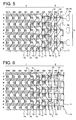
- FIG. 5 shows a third embodiment of the invention.
- the second warp knitting yarn 13 is woven between the third wale W3 and the fourth wale W4 located at a position where the tape body 1 of the fastener tape and the element attaching portion 2 are switched, and the tricot knitting yarn 12 is woven using the back needle BN instead of eliminating the second warp knitting yarn of the first to third wales W1 to W3 in the first embodiment.
- the tricot knitting yarn 12 is woven in the first wale W1 and the second wale W2 located on the side of the edge of the fastener tape.
- Other structure is the same as that of the first embodiment.
- the knitting by the second warp knitting yarn which maintains stable weaving mode and the knitting by the tricot knitting yarn 12 which provides a next structure in the element attaching portion 2 with slight resiliency in the tape longitudinal direction and the width direction are combined, the mode in the switching portion of the fastener tape body 1 and the element attaching portion 2 is stabilized, and flexibility in the element attaching portion 2 is secured.
- FIG. 6 shows a fourth embodiment of the invention.
- This example is different from the first embodiment in that a fastener element row 5 is woven in the element attaching portion 2 such that reversed portions 5d which connect coupling heads 5a and upper and lower legs 5b and 5c with each other in the elements of the fastener element row 5 which is continuously woven onto the element attaching portion 2 in a zigzag form are disposed in a reversed direction in the tape width direction. That is, in this embodiment, the coupling heads 5a of the fastener element row 5 extend toward the fastener tape body 1 beyond the element attaching portion 2, the reversed portions 5d of the fastener element row 5 are disposed side by side along an outer edge of the element attaching portion 2.
- the tape body 1 of the fastener tape and the element attaching portion 2 are folded into two along the tape length direction, and a cross section of the fastener tape edge is formed into a U-shape. Accordingly, a hidden slide fastener in which a coupling head 5a is coupled to another coupling head 5a of the opposed element row 5 is obtained.
- the embodiment of the hidden slide fastener has the above-described configuration, but in the other embodiments also, the knitting structures of the second and third embodiments can be employed as they are for the configuration itself of the fastener tape.
Landscapes
- Engineering & Computer Science (AREA)
- Textile Engineering (AREA)
- Slide Fasteners (AREA)
- Knitting Of Fabric (AREA)
- Knitting Machines (AREA)
- Woven Fabrics (AREA)
Abstract
Description
- The invention relates to a woven slide fastener which knits a fastener tape and which weaves and attaches a continuous fastener element row to a fastener element attaching portion of an edge portion on a longitudinal side of the fastener tape, and more particularly, to a woven slide fastener which knits the fastener element attaching portion using a double warp knitting machine.
- As a conventional woven slide fastener, according to Japanese Patent Application Laid-Open (JP-A) No.
10-5010 -
JP-A No. 2002-360316 - The fastener element of the fastener element attaching portion of the woven slide fastener which knits using the single-bed-type warp knitting machine disclosed in
Patent Documents - In
Patent Documents - To solve the problem of the single structure using the single-bed-type warp knitting machine,
JP-A No. 8-228813 JP-A No. 8-299034 JP-A No. 2005-230040 Patent Documents 3 to 5, the same fixing chain knitting yarn is knitted by double structure using front and back two rows of knitting-needles. - This will be described specifically. According to the fastener element attaching portion disclosed in
Patent Documents 3 to 5, its ground structure is knitted using a back needle row, and its fixing chain knitting yarn is knitted using front and back two rows of needle beds. Hence, a needle loop formed by the front needle row of the fixing chain knitting yarn is knitted to straddle the fastener element and in a subsequent course, a needle loop is formed by the front needle row, and a needle loop formed by the front needle row intermingles with the former needle loop, i.e., the needle loop is knitted by a so-called double structure. These are alternately repeated. That is, a needle loop for pressing a fastener element is formed using the front needle row on a leg of the fastener element disposed between two rows of courses, and during a subsequent course, when a needle loop of ground configuration knitting yarn is formed by the back needle row, the fixing chain knitting yarn is formed on the same back needle row by intermingling a needle loop of a next course with the former needle loop of the ground configuration knitting yarn at the same time. - Knitting yarns used for a ground structure knitted by the back needle row in the fastener element attaching portion disclosed in
Patent Documents 3 to 5 are warp knitting yarns of any of ground structure chain knitting yarns, tricot knitting yarns and second warp knitting yarns or a combination of them. A warp in-laid yarn or a weft in-laid yarn is inserted into a sinker loop of knitted stitches which are connected in a longitudinal direction or a width direction of the ground structure knitted by these knitting yarns. - Since the fixing chain knitting yarn is knitted onto the fastener element attaching portion such that the double structure using a double-bed-type warp knitting machine is included, the fastener element row is strongly attached to an edge portion on the longitudinal side of the warp knitting fastener tape stably in size, elongation of the fastener element attaching portion is suppressed at the same time, disengagement when the fastener chain is folded is eliminated, and smooth engagement can be carried out.
-
- Patent Document 1: Japanese Patent Application Laid-Open (JP-A) No.
10-5010 - Patent Document 2:
JP-A No. 2002-360316 - Patent Document 3:
JP-A No. 8-228813 - Patent Document 4:
JP-A No. 8-299034 - Patent Document 5:
JP-A No. 2005-230040 - The fastener element attaching portion of the woven slide fastener described in
Patent Documents 3 to 5 is fixed to the fastener element row by the fixing chain knitting yarn which is knitted while partially including double structure. Therefore, a form of the ground structure is stabilized and the above-described excellent effect is exerted. However, density of the fastener element attaching portion becomes high, double structure alternately exists between ground structure courses by the fixing chain knitting yarn of the fastener element attaching portion, and two needle loops of at least the ground structure chain knitting yarn and the fixing chain knitting yarn are formed by the same knitting-needle of the front tow. Therefore, a large load is applied to the front knitting-needle, and generation of breakage is increased. - Further, tension greater than those of other knitting yarns is applied to the fixing chain knitting yarn, if the fixing chain knitting yarn with high tension applied is intermingled with the ground structure, the ground structure is strongly fastened by the fixing chain knitting yarn, and hardness of the entire fastener element attaching portion is increased. As a result, characteristics of the warp knitting slide fastener which is originally required to have flexibility can not sufficiently be exerted. Especially in the case of thin, long and small slide fastener having narrow fastener tape width, the influence is great.
- It is a major object of the invention to provide a woven slide fastener in which the conventional fastener element attaching portion partially including the double structure is eliminated, flexibility which is originally required by warp woven slide fastener is secured, a knitting mode of the ground structure of the fastener element attaching portion is stabilized, and the fastener element row can be strongly supported and fixed.
- To achieve the above object, the invention provides a woven slide fastener including a tape body of a fastener tape, and a fastener element attaching portion disposed on an edge portion on a longitudinal side of the fastener tape, in which the fastener tape is knitted and a continuous fastener element row is knitted on the fastener tape at the same time using a double-bed-type double warp knitting machine, being characterized in that a fixing chain knitting yarn of a fastener element in the fastener element attaching portion and knitting yarns configuring a ground structure are knitted with independent single structures, respectively, needle loops which are connected to each other in a longitudinal direction of the fixing chain knitting yarn presses each of element legs of the continuous fastener element row toward the ground structure, sinker loops which are connected to each other in the longitudinal direction of the fixing chain knitting yarn go under a sinker loop of a knitting yarn which configures the ground structure and cross each other.
- According to preferable aspects, the knitting yarn which configures the ground structure includes a second warp knitting yarn, the sinker loop of the fixing chain knitting yarn goes under and crosses a sinker loop of the second warp knitting yarn. Preferably, all of wales of the tape body except a ground structure including a single structure of the fastener element attaching portion are knitted with a single structure which includes a tricot knitting yarn and a weft in-laid yarn. The fastener element attaching portion includes three or more wales, a ground structure includes a single structure of the fastener element attaching portion, the second warp knitting yarn is woven between the n-1-th wale which is most adjacent to the tape body and the n-th wale which is most adjacent to the fastener element attaching portion of the tape body, or a needle loop of the second warp knitting yarn woven in the n-th wale of the tape body which is most adjacent to the ground structure of the fastener element attaching portion including a single structure is knitted such that the needle loop of the second warp knitting yarn intertwines with a needle loop of a tricot yarn of the tape body which configures the n-th wale, or second warp knitting yarns are woven between all of wales of the ground structure which includes a single structure of the fastener element attaching portion, and a second warp knitting yarn is woven in a ground structure between the first wale on an outermost side of the fastener element attaching portion and the second wale which is adjacent to the first wale. Further, a chain knitting yarn is woven in three or more wales of the tape body including the wale having a single structure which is most adjacent to the fastener element attaching portion of the tape body.
- In the invention, the first feature is that when the fastener element attaching portion is knitted using the warp knitting machine having two or more needle beds, the needle loop of the ground structure of the fastener element attaching portion and the needle loop of the knitted portion of the fixing chain knitting yarn are independently knitted so that the needle loops do not intermingle with each other. By employing this configuration, the ground structure is independently knitted by the warp knitting needle row of one of the needle beds, the fixing chain knitting yarn is knitted by the warp knitting needle row of the other needle bed such that the leg of the fastener element is pressed toward the ground structure, the attaching operation and the fixing operation of the fastener element row by the ground structure and the fixing chain knitting yarn are separated, the phenomenon that the ground structure receives direct and strong restraint from the fixing chain knitting yarn is eliminated, a load applied to the warp knitting needle which knits the ground structure is reduced, and stability of the knitting mode of the ground structure is secured. As a result, flexibility of the entire fastener element attaching portion can be secured, and breakage of the warp knitting needle can be avoided.
- The second feature of the invention is that when the fastener element attaching portion is knitted, one of two or more warp knitting needle rows is exclusively used for the ground structure, other needle rows are used for knitting portion of the fixing chain knitting yarn, both the knitting operations are carried out independently, and when a second warp knitting yarn is included in the ground structure, the one second warp knitting yarn having one needle loop forms a needle loop through a sinker loop in the wale direction and the course direction and therefore, tension applied to the second warp knitting yarn is blocked between the needle loops and is not applied to the entire region, and the knitting mode of the entire ground structure is stabilized. In the invention, the sinker loops of the fixing chain knitting yarn and the second warp knitting yarn of the ground structure cross each other such that one of the sinker loops comes to a side opposite from the other sinker loop while avoiding intermixture of the needle loop of the ground structure and the needle loop of the fixing chain knitting portion, and the ground structure and the fixing chain knitting portion are connected to each other.
- By employing such a configuration, the fixing chain knitting portion and the ground structure are connected to each other through their sinker loops, the fastener element row is pressed toward the ground structure by the needle loop of the fixing chain knitting portion, the ground structure independently and strongly supports the fastener element row toward the fixing chain knitting portion, the knitting mode and flexibility of the ground structure are secured, and the fastener element row can be reliably, strongly and stably attached and fixed to the fastener element attaching portion without breaking the attaching mode of the element.
The invention will be understood in more detail by the following specific embodiments. -
-
FIG. 1 is a structure diagram of a warp knitting structure showing a first embodiment of a fastener stringer in a thin-width slide fastener which is a typical exemplary example of the invention. -
FIG. 2 is a structure diagram of configuration yarns of the fastener stringer of the embodiment. -
FIG. 3 is a partial enlarged cubic diagram schematically showing a partially cut-away fastener stringer of the embodiment. -
FIG. 4 is a structure diagram of a warp knitting structure showing a second embodiment of the invention. -
FIG. 5 is a structure diagram of a warp knitting structure showing a third embodiment of the invention. -
FIG. 6 is a structure diagram of a warp knitting structure showing a fourth embodiment of the invention. - A preferred exemplary example of the invention will be described specifically with reference to the drawings based on embodiments.
FIGS. 1 to 3 show a first embodiment of the invention. A woven slide fastener of the first embodiment is knitted by a warp knitting machine (e.g. , double raschel knitting machine) having two rows of back and front needle beds B and F. As shown inFIG. 1 , the woven slide fastener of the invention includes afastener tape body 1, and a fastenerelement attaching portion 2 on which anelement row 5 is attached. Theelement row 5 includes a large number of continuous fastener elements along one side edge in a longitudinal direction of thefastener tape body 1. According to the example shown in the drawing, the fastenerelement attaching portion 2 includes three wales (W1 to W3) arranged from outside. Ground structures of thefastener tape body 1 and theelement attaching portion 2 are knitted by a back needle BN. A fixingchain knitting yarn 10 which is woven by a front needle FN while pressing element legs of theelement row 5 toward the ground structure. - As shown in
FIGS. 1 and 2 , all of structure yarns configuring the ground structure of theelement attaching portion 2 are knitted by the back needle BN. The structure yarns include a chain knitting yarn 11 (1-0/0-0/0-1/1-1) which is knitted by the first wale W1, a tricot knitting yarn 12 (1-2/1-1/1-0/1-1) knitted between the third wale W3 and a fourth wale W4 which is adjacent to theelement attaching portion 2 of thefastener tape body 1, and three second warp knitting yarns 13 (0-2/2-2/2-0/0-0) which are sequentially knitted from the first wale W1 to the fourth wale W4. The fixing chain knitting yarn 10 (1-1/1-0/0-0/0-1) is knitted by the front needle FN on theelement attaching portion 2. - In this embodiment, a wale of the fastener
element attaching portion 2 which is most adjacent to thetape body 1 is the third wale W3, and a wale of thetape body 1 which is most adjacent to theelement attaching portion 2 is the fourth wale W4. - A knitting yarn which configures the ground structure forms a needle loop in every course along a single wale by the back needle BN. A needle loop of the
chain knitting yarn 11 linearly connects needle loops which are adjacent to each other in the longitudinal direction of the fastener tape by a sinker loop, and this becomes a portion of the ground structure. Thetricot knitting yarn 12 is a structure knitted such as to straddle two adjacent wales. After a needle loop is formed by the back needle BN, thetricot knitting yarn 12 is diagonally connected to a needle loop formed by the adjacent back needle BN in a next course using a sinker loop, and this becomes a portion of the ground structure. - As shown in
FIGS. 1 and 2 , thefastener tape body 1 is entirely knitted by the back needle BN. Thefastener tape body 1 includes the tricot knitting yarn 12 (1-2/1-1/1-0/1-1) which is knitted through all wales (W4 to Wm), the chain knitting yarn 11 (1-0/0-0/0-1/1-1) which is knitted in three wales, i.e., the fourth to sixth wales (W4 to W6), and a weft in-laid yarn 14 (0-0/2-2/4-4/2-2) which is inserted such that theyarn 14 straddles four wales in a zigzag form. A coil-shapedfastener element row 5 which is woven simultaneously with knitting of the fastener tape on theelement attaching portion 2 is a monofilament made of synthetic resin such as nylon and polyester, thefastener element row 5 runs such that it reciprocates in a lateral direction while changing a course C every three wales (W1 to W3) of theelement attaching portion 2. As shown inFIG. 3 , upper and lower legs 6 and 7 of each of the fastener elements are pressed toward the ground structure and fixed by the needle loop which is connected in the longitudinal direction (direction in which the wale extends) of the fastener tape of the fixingchain knitting yarn 10 on the two wales, i.e., the second and third wales W2 and W3. - Here, in the embodiment, in a warp knitting machine having the back and front two needle beds, all of the ground structures of the fastener tape are knitted by the back needle BN as described above, and the front needle knits the fixing chain knitting portion by the fixing
chain knitting yarn 10, and this is common in all of later-described other subsequent embodiments also. That is, the ground structure and the fixing chain knitting portion are knitted as independent single structures and this is one of features. However, the ground structure and the fixing chain knitting portion are knitted such that sinker loops of knitted stitches of a portion of weft knitting yarns of theconfiguration knitting yarns 11 to 13 of the ground structure and the fixingchain knitting yarn 10 cross each other while reversing their running positions, and the ground structure and the fixing chain knitting portion are integrally formed, and this is other feature. - This will be described specifically. In this embodiment, as shown in
FIG. 3 , the needle loop NP of the fixingchain knitting yarn 10 is knitted by the front needle FN such that the upper end lower legs of thefastener element row 5 which is .knitted on theelement attaching portion 2 is pressed toward the ground structure. At that time, the ground structure is knitted by the back needle BN at the same time. At the time of the simultaneous knitting operation by the front needle FN and the back needle BN, the sinker loop of the knitted stitch by the fixingchain knitting yarn 10 is made to run such that the sinker loop goes under (on the side of the back needle) a sinker loop of the secondwarp knitting yarns 13 and both the sinker loops cross each other. The secondwarp knitting yarns 13 sequentially forms knitted stitches (needle loops) along a wale direction and a course direction of the element attaching portion due to its structural reason. Therefore, tension is blocked every one knitted stitch in a tape length direction (wale direction) and a width direction (course direction). Hence, even if the secondwarp knitting yarns 13 crosses the sinker loop of the fixingchain knitting yarn 10, tension of the secondwarp knitting yarns 13 and tension of the fixingchain knitting yarn 10 are balanced, the knitting mode of the ground structure is not deformed, a double structure portion in which the needle loop of the fixing chain knitting yarn and the needle loop of the second warp knitting yarns intermingle with each other does not exists unlike the conventional technique, knitting density of theelement attaching portion 2 itself does not become dense, and although flexibility is secure, stable knitting mode is maintained. Since the needle loop of the ground structure and the needle loop of the fixing chain knitting portion do not intermingle with each other, an excessive load is not applied to the back needle BN, not only lifetime of the needle is increased but also the knitting speed is increased. - In this embodiment, three
chain knitting yarns 11 are woven together with thetricot knitting yarn 12 from the fourth wale W4 to the sixth wale W6 (tape body 1) of the fastener tape. Since the three wales W4 to W6 are sliding portions of a slider (not shown), they are made dense to enhance their strengths, and their surfaces are smoothened so that the slider slides smoothly. In the wales W4 to Wm-1 of thefastener tape body 1, the weft in-laidyarn 14 is inverted with a needle loop of thetricot knitting yarn 12 every four wales, and runs between the courses. Anotherchain knitting yarn 11 having the same structure is also knitted in the outermost wale opposite from theelement attaching portion 2 to stabilize a mode in the tape longitudinal direction. -
FIG. 4 shows a second embodiment of the invention. As shown inFIG. 4 , according to the second embodiment, the secondwarp knitting yarn 13 between the second wale W2 and the third wale W3 in the first embodiment is eliminated, and the tricot knitting yarn 12 (1-2/1-1/1-0/1-1) is knitted between the wales W2 and W3 by the back needle BN. Other structure is the same as that of the first embodiment. By employing the above-described structure in the second embodiment, only a partial second warp knitting yarn is eliminated from theelement attaching portion 2, this yarn is replaced by thetricot knitting yarn 12 in which a sinker loop diagonally extends between the adjacent wales. Therefore, thetricot knitting yarn 12 enhances flexibility of theelement attaching portion 2 utilizing the fact that thetricot knitting yarn 12 has resiliency in both the wale direction and course direction. -
FIG. 5 shows a third embodiment of the invention. In the third embodiment, the secondwarp knitting yarn 13 is woven between the third wale W3 and the fourth wale W4 located at a position where thetape body 1 of the fastener tape and theelement attaching portion 2 are switched, and thetricot knitting yarn 12 is woven using the back needle BN instead of eliminating the second warp knitting yarn of the first to third wales W1 to W3 in the first embodiment. Thetricot knitting yarn 12 is woven in the first wale W1 and the second wale W2 located on the side of the edge of the fastener tape. Other structure is the same as that of the first embodiment. In the third embodiment, according to the above-described configuration, resiliency in the wale direction and the course direction is suppressed at the switching position of thetape body 1 of the fastener tape and theelement attaching portion 2, the knitting by the second warp knitting yarn which maintains stable weaving mode and the knitting by thetricot knitting yarn 12 which provides a next structure in theelement attaching portion 2 with slight resiliency in the tape longitudinal direction and the width direction are combined, the mode in the switching portion of thefastener tape body 1 and theelement attaching portion 2 is stabilized, and flexibility in theelement attaching portion 2 is secured. -
FIG. 6 shows a fourth embodiment of the invention. This example is different from the first embodiment in that afastener element row 5 is woven in theelement attaching portion 2 such that reversedportions 5d which connectcoupling heads 5a and upper andlower legs fastener element row 5 which is continuously woven onto theelement attaching portion 2 in a zigzag form are disposed in a reversed direction in the tape width direction. That is, in this embodiment, the coupling heads 5a of thefastener element row 5 extend toward thefastener tape body 1 beyond theelement attaching portion 2, the reversedportions 5d of thefastener element row 5 are disposed side by side along an outer edge of theelement attaching portion 2. Other configuration is the same as that of the first embodiment. Thetape body 1 of the fastener tape and theelement attaching portion 2 are folded into two along the tape length direction, and a cross section of the fastener tape edge is formed into a U-shape. Accordingly, a hidden slide fastener in which acoupling head 5a is coupled to anothercoupling head 5a of theopposed element row 5 is obtained. The embodiment of the hidden slide fastener has the above-described configuration, but in the other embodiments also, the knitting structures of the second and third embodiments can be employed as they are for the configuration itself of the fastener tape. - The first to fourth embodiments are merely typical examples of the invention, and it will be understood that the invention can be variously modified without departing from a spirit of the invention.
-
- 1
- Fastener tape body (tape body)
- 2
- Fastener element attaching portion
- 5
- Element row
- 5a
- Coupling head
- 5b, 5c
- Upper and lower legs
- 5d
- Reversed portion
- 10
- Fixing chain knitting yarn
- 11
- Chain knitting yarn (of ground structure)
- 12
- Tricot knitting yarn (of ground structure)
- 13
- Second warp knitting yarn (of ground structure)
- 14
- Weft in-laid yarn (of ground structure)
Claims (9)
- A woven slide fastener including a tape body (1) of a fastener tape, and a fastener element attaching portion (2) disposed on an edge portion on a longitudinal side of the fastener tape, in which the fastener tape is knitted and a continuous fastener element row (5) is woven on the fastener element attaching portion (2) at the same time using a double-bed-type double warp knitting machine, being characterized in that
a fixing chain knitting yarn (10) of a fastener element in the fastener element attaching portion (2) and knitting yarns (11) to (14) configuring a ground structure are knitted with independent single structures, respectively, needle loops which are connected to each other in a longitudinal direction of the fixing chain knitting yarn (10) presses each of element legs of the continuous fastener element row (5) toward the ground structure, sinker loops which are connected to each other in the longitudinal direction of the fixing chain knitting yarn (10) go under a sinker loop of a knitting yarn which configures the ground structure and cross each other. - The woven slide fastener according to claim 1, being characterized in that the knitting yarn which configures the ground structure includes a second warp knitting yarn (13), the sinker loop of the fixing chain knitting yarn (10) goes under and crosses a sinker loop of the second warp knitting yarn (13) .
- The woven slide fastener according to claim 1 or 2, further including a hidden slide fastener.
- The woven slide fastener according to claim 2 or 3, being characterized in that all of wales (Wn to Wm) of the tape body (1) except a ground structure including a single structure of the fastener element attaching portion (2) are knitted with a single structure which includes a tricot knitting yarn (12) and a weft in-laid yarn (14).
- The woven slide fastener according to claim 4, being characterized in that the fastener element attaching portion (2) includes three or more wales (W1 to Wn-1), a ground structure includes a single structure of the fastener element attaching portion (2), the second warp knitting yarn (13) is woven between the n-1-th wale (Wn-1) which is most adjacent to the tape body (1) and the n-th wale (Wn) which is most adjacent to the fastener element attaching portion (2) of the tape body (1).
- The woven slide fastener according to claim 4, being characterized in that a needle loop of the second warp knitting yarn (13) woven in the n-th wale (Wn) of the tape body (1) which is most adjacent to the ground structure of the fastener element attaching portion (2) including a single structure is knitted such that the needle loop of the second warp knitting yarn (13) intertwines with a needle loop of a tricot yarn (14) of the tape body (1) which configures the n-th wale (Wn).
- The woven slide fastener according to claim 4, being characterized in that second warp knitting yarns (13) are woven between all of wales (W1 to Wn-1) of the ground structure which includes a single structure of the fastener element attaching portion (2).
- The woven slide fastener according to claim 4, being characterized in that a second warp knitting yarn (13) is woven in a ground structure between the first wale (W1) on an outermost side of the fastener element attaching portion (2) and the second wale (W2) which is adjacent to the first wale.
- The woven slide fastener according to claim 4, being characterized in that a chain knitting yarn is woven in three or more wales (Wn to Wn+2) of the tape body (1) including the wale (Wn) having a single structure which is most adjacent to the fastener element attaching portion (2) of the tape body (1) .
Applications Claiming Priority (1)
| Application Number | Priority Date | Filing Date | Title |
|---|---|---|---|
| PCT/JP2009/071669 WO2011077568A1 (en) | 2009-12-25 | 2009-12-25 | Woven slide fastener |
Publications (3)
| Publication Number | Publication Date |
|---|---|
| EP2517597A1 true EP2517597A1 (en) | 2012-10-31 |
| EP2517597A4 EP2517597A4 (en) | 2015-09-02 |
| EP2517597B1 EP2517597B1 (en) | 2016-09-07 |
Family
ID=44195128
Family Applications (1)
| Application Number | Title | Priority Date | Filing Date |
|---|---|---|---|
| EP09852583.5A Active EP2517597B1 (en) | 2009-12-25 | 2009-12-25 | Knit slide fastener |
Country Status (8)
| Country | Link |
|---|---|
| US (1) | US9320327B2 (en) |
| EP (1) | EP2517597B1 (en) |
| JP (1) | JP5318227B2 (en) |
| KR (1) | KR101388289B1 (en) |
| CN (1) | CN102686124B (en) |
| ES (1) | ES2602377T3 (en) |
| TW (1) | TWI400046B (en) |
| WO (1) | WO2011077568A1 (en) |
Families Citing this family (3)
| Publication number | Priority date | Publication date | Assignee | Title |
|---|---|---|---|---|
| WO2017098635A1 (en) * | 2015-12-10 | 2017-06-15 | Ykk株式会社 | Production method for stringer for woven slide fasteners and production device |
| US12016435B2 (en) | 2019-10-16 | 2024-06-25 | Ykk Corporation | Knitted fastener stringer, fastener chain, and method for manufacturing knitted fastener stringer |
| JP2022030892A (en) * | 2020-08-07 | 2022-02-18 | Ykk株式会社 | Knitted fastener stringer and cover member |
Family Cites Families (17)
| Publication number | Priority date | Publication date | Assignee | Title |
|---|---|---|---|---|
| US568177A (en) | 1896-09-22 | Tesla Nikola | Apparatus For Producing Ozone | |
| JPS59108502A (en) * | 1982-12-14 | 1984-06-23 | ワイケイケイ株式会社 | Water-proof slide fastener and production thereof |
| JP3398828B2 (en) * | 1994-06-23 | 2003-04-21 | ワイケイケイ株式会社 | Braided slide fastener |
| TW324158U (en) * | 1994-06-23 | 1998-01-01 | Ykk Corp | Knit slide fastener |
| JP3396335B2 (en) | 1995-05-12 | 2003-04-14 | ワイケイケイ株式会社 | Braided slide fastener |
| JP3407165B2 (en) * | 1995-05-18 | 2003-05-19 | ワイケイケイ株式会社 | Braided slide fastener |
| JP3406150B2 (en) | 1996-06-24 | 2003-05-12 | ワイケイケイ株式会社 | Braided slide fastener |
| JP3549677B2 (en) | 1996-08-08 | 2004-08-04 | Ykk株式会社 | Method and apparatus for manufacturing braided slide fastener stringers |
| JP3552947B2 (en) * | 1999-04-30 | 2004-08-11 | Ykk株式会社 | Braided slide fastener |
| JP2002360316A (en) | 2001-06-08 | 2002-12-17 | Ykk Corp | Braided slide fastener |
| DE60330811D1 (en) * | 2003-06-02 | 2010-02-11 | Ykk Corp | SPIRIT / FABRIC COVERED ZIPPER |
| JP4342841B2 (en) * | 2003-06-10 | 2009-10-14 | 有限会社アライウエビング | Slide fastener tape |
| JP4046699B2 (en) | 2004-02-17 | 2008-02-13 | Ykk株式会社 | Braided slide fastener |
| JP4450758B2 (en) * | 2005-03-25 | 2010-04-14 | Ykk株式会社 | Braided slide fastener |
| JP4731378B2 (en) * | 2006-03-31 | 2011-07-20 | Ykk株式会社 | Fastener tape and fastener stringer |
| GB0703849D0 (en) * | 2007-02-27 | 2007-04-11 | Ykk Europ Ltd | Zip fastener end stop |
| GB0912179D0 (en) * | 2009-07-13 | 2009-08-26 | Ykk Europ Ltd | Watertight zip fastener |
-
2009
- 2009-12-25 JP JP2011547177A patent/JP5318227B2/en active Active
- 2009-12-25 WO PCT/JP2009/071669 patent/WO2011077568A1/en not_active Ceased
- 2009-12-25 ES ES09852583.5T patent/ES2602377T3/en active Active
- 2009-12-25 EP EP09852583.5A patent/EP2517597B1/en active Active
- 2009-12-25 CN CN200980163123.4A patent/CN102686124B/en active Active
- 2009-12-25 US US13/517,986 patent/US9320327B2/en active Active
- 2009-12-25 KR KR1020127016320A patent/KR101388289B1/en active Active
-
2010
- 2010-06-01 TW TW099117618A patent/TWI400046B/en active
Also Published As
| Publication number | Publication date |
|---|---|
| US9320327B2 (en) | 2016-04-26 |
| HK1174508A1 (en) | 2013-06-14 |
| TWI400046B (en) | 2013-07-01 |
| US20120279025A1 (en) | 2012-11-08 |
| WO2011077568A1 (en) | 2011-06-30 |
| TW201121456A (en) | 2011-07-01 |
| KR20120073375A (en) | 2012-07-04 |
| KR101388289B1 (en) | 2014-04-22 |
| ES2602377T3 (en) | 2017-02-20 |
| EP2517597A4 (en) | 2015-09-02 |
| CN102686124A (en) | 2012-09-19 |
| JPWO2011077568A1 (en) | 2013-05-02 |
| JP5318227B2 (en) | 2013-10-16 |
| EP2517597B1 (en) | 2016-09-07 |
| CN102686124B (en) | 2015-01-28 |
Similar Documents
| Publication | Publication Date | Title |
|---|---|---|
| JP4046699B2 (en) | Braided slide fastener | |
| EP1839514B1 (en) | Fastener tape and fastener stringer | |
| JP3552947B2 (en) | Braided slide fastener | |
| EP2517597B1 (en) | Knit slide fastener | |
| KR960041452A (en) | Knit slide fastener | |
| TW201304703A (en) | Braided fastener stringer | |
| US5257515A (en) | Stringer for a concealed type of slide fastener | |
| US7240521B2 (en) | Knitted-in slide fastener | |
| CN1883330B (en) | Production machines for warp knitted zipper tapes | |
| WO2009128140A1 (en) | Fastener stringer for knitting slide fastner | |
| US9648927B2 (en) | Warp-knitted tape of zipper | |
| HK1174508B (en) | Woven slide fastener | |
| CN112654272A (en) | Fastener stringer and slide fastener | |
| HK1076363B (en) | Knitted slide fastener | |
| HK1106403B (en) | Fastener tape and fastener stringer | |
| HK1092025B (en) | Knitted-in slide fastener |
Legal Events
| Date | Code | Title | Description |
|---|---|---|---|
| PUAI | Public reference made under article 153(3) epc to a published international application that has entered the european phase |
Free format text: ORIGINAL CODE: 0009012 |
|
| 17P | Request for examination filed |
Effective date: 20120621 |
|
| AK | Designated contracting states |
Kind code of ref document: A1 Designated state(s): AT BE BG CH CY CZ DE DK EE ES FI FR GB GR HR HU IE IS IT LI LT LU LV MC MK MT NL NO PL PT RO SE SI SK SM TR |
|
| DAX | Request for extension of the european patent (deleted) | ||
| RA4 | Supplementary search report drawn up and despatched (corrected) |
Effective date: 20150731 |
|
| RIC1 | Information provided on ipc code assigned before grant |
Ipc: A44B 19/56 20060101AFI20150727BHEP |
|
| GRAP | Despatch of communication of intention to grant a patent |
Free format text: ORIGINAL CODE: EPIDOSNIGR1 |
|
| INTG | Intention to grant announced |
Effective date: 20160323 |
|
| RAP1 | Party data changed (applicant data changed or rights of an application transferred) |
Owner name: YKK CORPORATION |
|
| GRAS | Grant fee paid |
Free format text: ORIGINAL CODE: EPIDOSNIGR3 |
|
| GRAP | Despatch of communication of intention to grant a patent |
Free format text: ORIGINAL CODE: EPIDOSNIGR1 |
|
| GRAA | (expected) grant |
Free format text: ORIGINAL CODE: 0009210 |
|
| INTG | Intention to grant announced |
Effective date: 20160726 |
|
| AK | Designated contracting states |
Kind code of ref document: B1 Designated state(s): AT BE BG CH CY CZ DE DK EE ES FI FR GB GR HR HU IE IS IT LI LT LU LV MC MK MT NL NO PL PT RO SE SI SK SM TR |
|
| REG | Reference to a national code |
Ref country code: GB Ref legal event code: FG4D |
|
| REG | Reference to a national code |
Ref country code: CH Ref legal event code: EP |
|
| REG | Reference to a national code |
Ref country code: IE Ref legal event code: FG4D |
|
| REG | Reference to a national code |
Ref country code: AT Ref legal event code: REF Ref document number: 826022 Country of ref document: AT Kind code of ref document: T Effective date: 20161015 |
|
| REG | Reference to a national code |
Ref country code: DE Ref legal event code: R096 Ref document number: 602009041066 Country of ref document: DE |
|
| REG | Reference to a national code |
Ref country code: FR Ref legal event code: PLFP Year of fee payment: 8 |
|
| REG | Reference to a national code |
Ref country code: LT Ref legal event code: MG4D |
|
| REG | Reference to a national code |
Ref country code: NL Ref legal event code: MP Effective date: 20160907 |
|
| PG25 | Lapsed in a contracting state [announced via postgrant information from national office to epo] |
Ref country code: HR Free format text: LAPSE BECAUSE OF FAILURE TO SUBMIT A TRANSLATION OF THE DESCRIPTION OR TO PAY THE FEE WITHIN THE PRESCRIBED TIME-LIMIT Effective date: 20160907 Ref country code: LT Free format text: LAPSE BECAUSE OF FAILURE TO SUBMIT A TRANSLATION OF THE DESCRIPTION OR TO PAY THE FEE WITHIN THE PRESCRIBED TIME-LIMIT Effective date: 20160907 Ref country code: NO Free format text: LAPSE BECAUSE OF FAILURE TO SUBMIT A TRANSLATION OF THE DESCRIPTION OR TO PAY THE FEE WITHIN THE PRESCRIBED TIME-LIMIT Effective date: 20161207 Ref country code: FI Free format text: LAPSE BECAUSE OF FAILURE TO SUBMIT A TRANSLATION OF THE DESCRIPTION OR TO PAY THE FEE WITHIN THE PRESCRIBED TIME-LIMIT Effective date: 20160907 |
|
| REG | Reference to a national code |
Ref country code: AT Ref legal event code: MK05 Ref document number: 826022 Country of ref document: AT Kind code of ref document: T Effective date: 20160907 |
|
| REG | Reference to a national code |
Ref country code: ES Ref legal event code: FG2A Ref document number: 2602377 Country of ref document: ES Kind code of ref document: T3 Effective date: 20170220 |
|
| PG25 | Lapsed in a contracting state [announced via postgrant information from national office to epo] |
Ref country code: GR Free format text: LAPSE BECAUSE OF FAILURE TO SUBMIT A TRANSLATION OF THE DESCRIPTION OR TO PAY THE FEE WITHIN THE PRESCRIBED TIME-LIMIT Effective date: 20161208 Ref country code: SE Free format text: LAPSE BECAUSE OF FAILURE TO SUBMIT A TRANSLATION OF THE DESCRIPTION OR TO PAY THE FEE WITHIN THE PRESCRIBED TIME-LIMIT Effective date: 20160907 Ref country code: LV Free format text: LAPSE BECAUSE OF FAILURE TO SUBMIT A TRANSLATION OF THE DESCRIPTION OR TO PAY THE FEE WITHIN THE PRESCRIBED TIME-LIMIT Effective date: 20160907 Ref country code: NL Free format text: LAPSE BECAUSE OF FAILURE TO SUBMIT A TRANSLATION OF THE DESCRIPTION OR TO PAY THE FEE WITHIN THE PRESCRIBED TIME-LIMIT Effective date: 20160907 |
|
| PG25 | Lapsed in a contracting state [announced via postgrant information from national office to epo] |
Ref country code: RO Free format text: LAPSE BECAUSE OF FAILURE TO SUBMIT A TRANSLATION OF THE DESCRIPTION OR TO PAY THE FEE WITHIN THE PRESCRIBED TIME-LIMIT Effective date: 20160907 Ref country code: EE Free format text: LAPSE BECAUSE OF FAILURE TO SUBMIT A TRANSLATION OF THE DESCRIPTION OR TO PAY THE FEE WITHIN THE PRESCRIBED TIME-LIMIT Effective date: 20160907 |
|
| PG25 | Lapsed in a contracting state [announced via postgrant information from national office to epo] |
Ref country code: PT Free format text: LAPSE BECAUSE OF FAILURE TO SUBMIT A TRANSLATION OF THE DESCRIPTION OR TO PAY THE FEE WITHIN THE PRESCRIBED TIME-LIMIT Effective date: 20170109 Ref country code: BG Free format text: LAPSE BECAUSE OF FAILURE TO SUBMIT A TRANSLATION OF THE DESCRIPTION OR TO PAY THE FEE WITHIN THE PRESCRIBED TIME-LIMIT Effective date: 20161207 Ref country code: AT Free format text: LAPSE BECAUSE OF FAILURE TO SUBMIT A TRANSLATION OF THE DESCRIPTION OR TO PAY THE FEE WITHIN THE PRESCRIBED TIME-LIMIT Effective date: 20160907 Ref country code: IS Free format text: LAPSE BECAUSE OF FAILURE TO SUBMIT A TRANSLATION OF THE DESCRIPTION OR TO PAY THE FEE WITHIN THE PRESCRIBED TIME-LIMIT Effective date: 20170107 Ref country code: CZ Free format text: LAPSE BECAUSE OF FAILURE TO SUBMIT A TRANSLATION OF THE DESCRIPTION OR TO PAY THE FEE WITHIN THE PRESCRIBED TIME-LIMIT Effective date: 20160907 Ref country code: BE Free format text: LAPSE BECAUSE OF FAILURE TO SUBMIT A TRANSLATION OF THE DESCRIPTION OR TO PAY THE FEE WITHIN THE PRESCRIBED TIME-LIMIT Effective date: 20160907 Ref country code: SK Free format text: LAPSE BECAUSE OF FAILURE TO SUBMIT A TRANSLATION OF THE DESCRIPTION OR TO PAY THE FEE WITHIN THE PRESCRIBED TIME-LIMIT Effective date: 20160907 Ref country code: PL Free format text: LAPSE BECAUSE OF FAILURE TO SUBMIT A TRANSLATION OF THE DESCRIPTION OR TO PAY THE FEE WITHIN THE PRESCRIBED TIME-LIMIT Effective date: 20160907 Ref country code: SM Free format text: LAPSE BECAUSE OF FAILURE TO SUBMIT A TRANSLATION OF THE DESCRIPTION OR TO PAY THE FEE WITHIN THE PRESCRIBED TIME-LIMIT Effective date: 20160907 |
|
| REG | Reference to a national code |
Ref country code: DE Ref legal event code: R097 Ref document number: 602009041066 Country of ref document: DE |
|
| PLBE | No opposition filed within time limit |
Free format text: ORIGINAL CODE: 0009261 |
|
| STAA | Information on the status of an ep patent application or granted ep patent |
Free format text: STATUS: NO OPPOSITION FILED WITHIN TIME LIMIT |
|
| PG25 | Lapsed in a contracting state [announced via postgrant information from national office to epo] |
Ref country code: DK Free format text: LAPSE BECAUSE OF FAILURE TO SUBMIT A TRANSLATION OF THE DESCRIPTION OR TO PAY THE FEE WITHIN THE PRESCRIBED TIME-LIMIT Effective date: 20160907 |
|
| REG | Reference to a national code |
Ref country code: CH Ref legal event code: PL |
|
| 26N | No opposition filed |
Effective date: 20170608 |
|
| PG25 | Lapsed in a contracting state [announced via postgrant information from national office to epo] |
Ref country code: SI Free format text: LAPSE BECAUSE OF FAILURE TO SUBMIT A TRANSLATION OF THE DESCRIPTION OR TO PAY THE FEE WITHIN THE PRESCRIBED TIME-LIMIT Effective date: 20160907 |
|
| PG25 | Lapsed in a contracting state [announced via postgrant information from national office to epo] |
Ref country code: MC Free format text: LAPSE BECAUSE OF FAILURE TO SUBMIT A TRANSLATION OF THE DESCRIPTION OR TO PAY THE FEE WITHIN THE PRESCRIBED TIME-LIMIT Effective date: 20160907 |
|
| REG | Reference to a national code |
Ref country code: IE Ref legal event code: MM4A |
|
| PG25 | Lapsed in a contracting state [announced via postgrant information from national office to epo] |
Ref country code: LI Free format text: LAPSE BECAUSE OF NON-PAYMENT OF DUE FEES Effective date: 20161231 Ref country code: LU Free format text: LAPSE BECAUSE OF NON-PAYMENT OF DUE FEES Effective date: 20161225 Ref country code: CH Free format text: LAPSE BECAUSE OF NON-PAYMENT OF DUE FEES Effective date: 20161231 |
|
| REG | Reference to a national code |
Ref country code: FR Ref legal event code: PLFP Year of fee payment: 9 |
|
| PG25 | Lapsed in a contracting state [announced via postgrant information from national office to epo] |
Ref country code: IE Free format text: LAPSE BECAUSE OF NON-PAYMENT OF DUE FEES Effective date: 20161225 |
|
| PG25 | Lapsed in a contracting state [announced via postgrant information from national office to epo] |
Ref country code: CY Free format text: LAPSE BECAUSE OF FAILURE TO SUBMIT A TRANSLATION OF THE DESCRIPTION OR TO PAY THE FEE WITHIN THE PRESCRIBED TIME-LIMIT Effective date: 20160907 Ref country code: HU Free format text: LAPSE BECAUSE OF FAILURE TO SUBMIT A TRANSLATION OF THE DESCRIPTION OR TO PAY THE FEE WITHIN THE PRESCRIBED TIME-LIMIT; INVALID AB INITIO Effective date: 20091225 |
|
| PG25 | Lapsed in a contracting state [announced via postgrant information from national office to epo] |
Ref country code: MK Free format text: LAPSE BECAUSE OF FAILURE TO SUBMIT A TRANSLATION OF THE DESCRIPTION OR TO PAY THE FEE WITHIN THE PRESCRIBED TIME-LIMIT Effective date: 20160907 |
|
| PG25 | Lapsed in a contracting state [announced via postgrant information from national office to epo] |
Ref country code: MT Free format text: LAPSE BECAUSE OF NON-PAYMENT OF DUE FEES Effective date: 20161225 |
|
| PGFP | Annual fee paid to national office [announced via postgrant information from national office to epo] |
Ref country code: DE Payment date: 20191210 Year of fee payment: 11 |
|
| PGFP | Annual fee paid to national office [announced via postgrant information from national office to epo] |
Ref country code: FR Payment date: 20191115 Year of fee payment: 11 |
|
| PGFP | Annual fee paid to national office [announced via postgrant information from national office to epo] |
Ref country code: ES Payment date: 20200102 Year of fee payment: 11 Ref country code: GB Payment date: 20191223 Year of fee payment: 11 |
|
| REG | Reference to a national code |
Ref country code: DE Ref legal event code: R119 Ref document number: 602009041066 Country of ref document: DE |
|
| GBPC | Gb: european patent ceased through non-payment of renewal fee |
Effective date: 20201225 |
|
| PG25 | Lapsed in a contracting state [announced via postgrant information from national office to epo] |
Ref country code: FR Free format text: LAPSE BECAUSE OF NON-PAYMENT OF DUE FEES Effective date: 20201231 |
|
| PG25 | Lapsed in a contracting state [announced via postgrant information from national office to epo] |
Ref country code: DE Free format text: LAPSE BECAUSE OF NON-PAYMENT OF DUE FEES Effective date: 20210701 Ref country code: GB Free format text: LAPSE BECAUSE OF NON-PAYMENT OF DUE FEES Effective date: 20201225 |
|
| REG | Reference to a national code |
Ref country code: ES Ref legal event code: FD2A Effective date: 20220411 |
|
| PG25 | Lapsed in a contracting state [announced via postgrant information from national office to epo] |
Ref country code: ES Free format text: LAPSE BECAUSE OF NON-PAYMENT OF DUE FEES Effective date: 20201226 |
|
| P01 | Opt-out of the competence of the unified patent court (upc) registered |
Effective date: 20230428 |
|
| PGFP | Annual fee paid to national office [announced via postgrant information from national office to epo] |
Ref country code: IT Payment date: 20251121 Year of fee payment: 17 |
|
| PGFP | Annual fee paid to national office [announced via postgrant information from national office to epo] |
Ref country code: TR Payment date: 20251224 Year of fee payment: 17 |