EP2517449B1 - System for the reception of satellite data - Google Patents
System for the reception of satellite data Download PDFInfo
- Publication number
- EP2517449B1 EP2517449B1 EP10796041.1A EP10796041A EP2517449B1 EP 2517449 B1 EP2517449 B1 EP 2517449B1 EP 10796041 A EP10796041 A EP 10796041A EP 2517449 B1 EP2517449 B1 EP 2517449B1
- Authority
- EP
- European Patent Office
- Prior art keywords
- vehicle
- suited
- interface housing
- antenna
- transmitter coil
- Prior art date
- Legal status (The legal status is an assumption and is not a legal conclusion. Google has not performed a legal analysis and makes no representation as to the accuracy of the status listed.)
- Not-in-force
Links
Images

Classifications
-
- B—PERFORMING OPERATIONS; TRANSPORTING
- B60—VEHICLES IN GENERAL
- B60R—VEHICLES, VEHICLE FITTINGS, OR VEHICLE PARTS, NOT OTHERWISE PROVIDED FOR
- B60R11/00—Arrangements for holding or mounting articles, not otherwise provided for
- B60R11/02—Arrangements for holding or mounting articles, not otherwise provided for for radio sets, television sets, telephones, or the like; Arrangement of controls thereof
- B60R11/0241—Arrangements for holding or mounting articles, not otherwise provided for for radio sets, television sets, telephones, or the like; Arrangement of controls thereof for telephones
-
- H—ELECTRICITY
- H04—ELECTRIC COMMUNICATION TECHNIQUE
- H04B—TRANSMISSION
- H04B1/00—Details of transmission systems, not covered by a single one of groups H04B3/00 - H04B13/00; Details of transmission systems not characterised by the medium used for transmission
- H04B1/38—Transceivers, i.e. devices in which transmitter and receiver form a structural unit and in which at least one part is used for functions of transmitting and receiving
- H04B1/3822—Transceivers, i.e. devices in which transmitter and receiver form a structural unit and in which at least one part is used for functions of transmitting and receiving specially adapted for use in vehicles
-
- H—ELECTRICITY
- H04—ELECTRIC COMMUNICATION TECHNIQUE
- H04M—TELEPHONIC COMMUNICATION
- H04M1/00—Substation equipment, e.g. for use by subscribers
- H04M1/72—Mobile telephones; Cordless telephones, i.e. devices for establishing wireless links to base stations without route selection
- H04M1/724—User interfaces specially adapted for cordless or mobile telephones
- H04M1/72403—User interfaces specially adapted for cordless or mobile telephones with means for local support of applications that increase the functionality
- H04M1/72409—User interfaces specially adapted for cordless or mobile telephones with means for local support of applications that increase the functionality by interfacing with external accessories
- H04M1/72412—User interfaces specially adapted for cordless or mobile telephones with means for local support of applications that increase the functionality by interfacing with external accessories using two-way short-range wireless interfaces
-
- H—ELECTRICITY
- H04—ELECTRIC COMMUNICATION TECHNIQUE
- H04M—TELEPHONIC COMMUNICATION
- H04M2250/00—Details of telephonic subscriber devices
- H04M2250/02—Details of telephonic subscriber devices including a Bluetooth® interface
-
- H—ELECTRICITY
- H04—ELECTRIC COMMUNICATION TECHNIQUE
- H04M—TELEPHONIC COMMUNICATION
- H04M2250/00—Details of telephonic subscriber devices
- H04M2250/06—Details of telephonic subscriber devices including a wireless LAN interface
Definitions
- the present invention concerns a system for the reception of satellite data for a vehicle for the transmission of data originating from a satellite towards user terminals.
- the invention finds an application of particular interest within the framework of the diffusion of data towards mobile user terminals which a motor vehicle comprises, via a satellite.
- Certain satellites are nowadays likely to integrate a payload allowing the distribution of applications and contents to be ensured towards portable mobile terminals and vehicles.
- the main problem posed by the distribution of applications and contents by satellite towards portable mobile terminals lies in the fact that very few mobile terminals exist which are capable of receiving directly the signal emitted by a satellite. This therefore necessitates using an adapted receiver to process the received signals and to transmit the processed signals to the mobile terminals.
- the devices for the reception of satellite data equipping vehicles comprise an antenna situated on the exterior of the passenger compartment of the motor vehicle and a receiver situated in the passenger compartment.
- the satellite signals received by the antenna are immediately retransmitted to the receiver via a wired connection.
- the latter comprises in particular an amplifier and a demodulator so as to adapt the signals picked up by the exterior antenna to retransmit them to a determined mobile user terminal situated in the passenger compartment of the vehicle.
- a disadvantage in this type of device lies in the fact that an opening must be made in the bodywork to fix the external antenna there and to connect the latter, by means of a cable, to a receiver which is situated in the passenger compartment, this cable being able to serve both for the transmission of data and for the electrical supply of the antenna.
- the receiver is further connected physically by means of a cable to the battery of the motor vehicle (for example via a connection to the cigarette-lighter).
- Systems for the reception of satellite data in vehicles are known for example from documents WO 2005/125207 or XP 007914251.
- the principle of power transfer carried out from a transmitter coil towards a receiver coil is known from document US 2004 1427 33 .
- the present invention aims to provide a transmission system of satellite data towards user terminals, the said system being intended to be installed in a vehicle such as a motor vehicle and allowing the greatest possible number of terminals to be connected, including the terminals which are not adapted to receive satellite signals, whilst avoiding the problems linked to the installation of such a system, in particular the problems linked to the wiring of this system.
- the system is of particular interest for an installation in vehicles which are already in circulation.
- the invention aims to propose a system for the reception of satellite data, the installation of which is able to be easily realized and is low in cost.
- the invention relates to a system for the reception of satellite data for a vehicle, the said system comprising:
- window designates the front or rear window panel of the vehicle, a panoramic roof, an opening roof or else a window of the vehicle.
- the system according to the invention is, however, preferably implemented on the front window panel of the vehicle.
- the transfer of data from the exterior interface housing (situated on the roof of the vehicle) towards a mobile user terminal (situated in the passenger compartment of the vehicle) does not require any complex installation, since the system according to the invention does not use any wires:
- the system according to the invention is totally wireless; the system therefore allows one to avoid the use of cables for the transmission of data and/or energy; consequently, no opening has to be made in the bodywork.
- the installation of a system according to the invention is therefore greatly facilitated, involving in fact a great reduction in cost.
- the system according to the invention allows the satellite signals received by the antenna to be adapted so that they are compatible with the formats recognized by the terminals.
- these terminals can be mobile terminals belonging to the driver or to the passenger(s) of the vehicle or terminals provided with a wireless dialogue interface integrated on board the vehicle.
- the system for the reception of data according to the invention can have one or more supplementary characteristics below, considered individually or according to all the technically realizable combinations:
- the invention further relates to a motor vehicle, characterized in that it comprises a system for the reception of satellite data in accordance with the system of the invention.
- the said second part of the said interface housing is situated opposite a non-shielded part of the window of the vehicle.
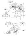
- FIG. 1 illustrates a whole view and an enlargement Z of a system 1 for the reception of satellite data according to the invention equipping a vehicle 2.
- the system 1 comprises in particular an interface housing 3 and a transmitter coil 5.
- the interface housing 3 is suited to ensure the interface between a telecommunications satellite 6 and user terminals 7 (a single one is represented), such as mobile terminals (of the PMP "Portable MultiMedia Player” type, PDA “Personal Digital Assistant” type or else a mobile telephone) situated inside the vehicle 2, via a wireless local network 8 of the WiFi, WiMax, wireless USB, DLNA, UPnP or BlueTooth type.
- the interface housing 3 has a profiled shape forming a first part P1 arranged on a bodywork element, such as for example on the roof 9 of the vehicle 2, and a second part P2 extending via a curve the first part P1 arranged close to the front window 4 of the vehicle 2.
- the first part P1 of the interface housing 3 comprises:
- the second part P2 of the interface housing comprises:
- the interface housing 3 does not just pick up signals which arrive from any satellite 6 to retransmit them immediately to a mobile user terminal 7, but it adapts them into IP packets so that they are compatible with the formats recognized by the majority of the terminals 7 which support the processing at the level of the IP layer (in particular the mobile terminals 7). In this way, the user terminal 7 does not need to be compatible to receive satellite signals 6 since it is connected to the interface housing 3 by means of the local wireless network 8.
- the supplying of the interface housing 3 is carried out by means of the transmitter coil 5 and the receiver coil 17.
- the transmitter coil 5 is connected to the battery 18 of the vehicle 2 by means of a cable 19 comprising, at one of its ends, an adapter 20 of the cigarette-lighter type suited to be inserted into a cigarette-lighter socket (not shown) which the vehicle 2 comprises.
- the transmitter coil 5 When the transmitter coil 5 is supplied with energy, it creates a magnetic field 21 oscillating at a determined resonance frequency, this resonance frequency being fixed by a first generator circuit of a signal at the said resonance frequency to which the transmitter coil 5 is connected.
- the magnetic field 21 induces a magnetic field 22 to the receiver coil 17, which aligns itself on the same resonance frequency as that of the transmitter coil 5.
- the resonance frequency of the transmitter and receiver coils 5 and 17 allows a strong connection to be established between them and allows power to be exchanged.
- the distance separating the transmitter coil 5 from the receiver coil 17 is strictly less than eight times the radius of the transmitter coil 5 or receiver coil 17.
- the diameter of the transmitter and receiver coils 5 and 17 can be between 1 and 8 cm. It should also be noted that the transmitter 5 and receiver 17 coils have an identical radius.
- the resonance frequency of the transmitter and receiver coils 5 and 17 is selected so as:
- the first part P1 of the interface housing 3 comprises the antenna 10, which is positioned in a substantially horizontal manner, in other words the antenna 10 is substantially parallel to the roof 9 of the vehicle 2.
- the antenna 10 is substantially parallel to the roof 9 of the vehicle 2.
- the receiver coil 17 is situated in the second part P2 of the interface housing 3.
- the transmitter and receiver coils 5 and 17 are positioned facing each other and separated by the window 4 of the vehicle 2.
- the transmitter and receiver coils 5 and 17 are preferably positioned in a non-shielded area of the window 4 to optimize the transfer of power. In a conventional manner, such a non-shielded area is situated in the rear part of the rear view mirror in the passenger compartment.
- the connection means 16 are situated in the second part P2 and more particularly opposite the non-shielded area such that the data transmitted by the connection means 16 do not undergo to great attenuation.
- a particularly interesting application of the system 1 according to the invention consists in installing an interface housing 3 on the roof 9 of a motor vehicle 2.
- the system 1 will allow the occupants of the vehicle 2 to benefit from the connectivity by using their own terminals 7, not necessarily adapted to satellite reception.
- the terminals installed on board the vehicle will also benefit from this connectivity. It will be sufficient, for example, to connect, via the local network 8, one's mobile telephone 7 to the interface housing 3 on board in one's car 2 to consult the weather forecast, to use on demand music services or to watch satellite television.
- the interface housing 3 can be made integral with the vehicle 2 by any type of fixing means (not shown) such as for example a series of magnetic feet surrounded by a rubber protection, a series of suction cups or of adhesive pads of the Velcro TM type. These fixing means are detachable fixing means.
- the fixing means can be formed by attachment means comprising a secured closure ensured for example by means of a lock.
- the interface housing 3 can be positioned on the ledge of a window 4 or on the window 4 of a building 23 by means of suction cups.
- the transmitter coil 5 is positioned inside the building 23 and close to the interface housing 3, which comprises the receiver coil 17.
- the transmitter coil 5 is connected to the electrical network of the building 23 by means of an adapter 20 of the sector type. In this way, the passengers of the vehicle can continue to benefit from the services which the system 1 offered to them during their journey.
- the interface housing 3 can be equipped with a rechargeable battery.
- the rechargeable battery supplies, for example, the processing means 11 and/or the connection means 16.
- the interface housing 3 can function in an autonomous manner over a short period.
- Figure 3 illustrates a different implementation of the invention, in which the antenna 10 of the interface housing 3 is mounted in rotation about an axis 24 such that the antenna can present at least two perpendicular stable positions.
- the antenna 10 is likewise found in vertical position.
- a vertical positioning of the antenna 10 is not optimal for the reception of satellite signals. So as to remedy such a deficiency, the antenna 10 is pivoted up to an angle of 90°. This latter is therefore in optimum position.
- the antenna 10 can be positioned according to a determined angle comprised in a range varying from 0 to 90 degrees.
- the antenna 10 can also be pivoted so as to pick up more efficiently the signals originating from a terrestrial antenna, such as for example the signals of the TDT type (for terrestrial digital television).
- the system 1 is primarily adapted for use in motor vehicles, but it can also be used at home or at any other location, such as for example on a beach, owing to the rechargeable battery.
- the system 1 can be an integrating part of a motor vehicle 2.
- a car manufacturer can present the system 1 as an option which the purchaser can select.
- the interface housing 3 has a profiled shape forming a first part P1 suited to be arranged on a bodywork element, such as for example on the roof 9 of the vehicle 2, and a second part P2 extending via a curve the first part P1 suited to be arranged close to the front window 4 of the vehicle 2.
- the housing can also be positioned at the level of a panoramic roof present on the vehicle.
- the panoramic roofs usually comprise an upper convex part.
- the part P2 therefore extends the first part P1 which is fixed on the roof of the vehicle so as to be arranged close to the upper convex part of the panoramic roof of the vehicle.
- system 1 is distinguished in that:
- the mobile terminals do not need to adapt themselves to the satellite signals since the system 1 adapts the said signals to the mobile terminals 7.
- the invention is not limited to the embodiment which has just been described.
- the invention has been more particularly described in the case where the received signals are satellite signals.
- reception means suited to receive signals originating from a terrestrial antenna.
Landscapes
- Engineering & Computer Science (AREA)
- Computer Networks & Wireless Communication (AREA)
- Signal Processing (AREA)
- Human Computer Interaction (AREA)
- Mechanical Engineering (AREA)
- Radio Relay Systems (AREA)
- Fittings On The Vehicle Exterior For Carrying Loads, And Devices For Holding Or Mounting Articles (AREA)
Description
- The present invention concerns a system for the reception of satellite data for a vehicle for the transmission of data originating from a satellite towards user terminals. The invention finds an application of particular interest within the framework of the diffusion of data towards mobile user terminals which a motor vehicle comprises, via a satellite.
- Certain satellites (this is the case in particular with satellites in band S) are nowadays likely to integrate a payload allowing the distribution of applications and contents to be ensured towards portable mobile terminals and vehicles.
- Such a configuration is, however, likely to pose two major difficulties.
- Thus, the main problem posed by the distribution of applications and contents by satellite towards portable mobile terminals lies in the fact that very few mobile terminals exist which are capable of receiving directly the signal emitted by a satellite. This therefore necessitates using an adapted receiver to process the received signals and to transmit the processed signals to the mobile terminals.
- Furthermore, in a known manner, the devices for the reception of satellite data equipping vehicles comprise an antenna situated on the exterior of the passenger compartment of the motor vehicle and a receiver situated in the passenger compartment. The satellite signals received by the antenna are immediately retransmitted to the receiver via a wired connection. The latter comprises in particular an amplifier and a demodulator so as to adapt the signals picked up by the exterior antenna to retransmit them to a determined mobile user terminal situated in the passenger compartment of the vehicle.
- A disadvantage in this type of device lies in the fact that an opening must be made in the bodywork to fix the external antenna there and to connect the latter, by means of a cable, to a receiver which is situated in the passenger compartment, this cable being able to serve both for the transmission of data and for the electrical supply of the antenna. The receiver is further connected physically by means of a cable to the battery of the motor vehicle (for example via a connection to the cigarette-lighter). Systems for the reception of satellite data in vehicles are known for example from documents
WO 2005/125207 or XP 007914251. Moreover, the principle of power transfer carried out from a transmitter coil towards a receiver coil is known from documentUS 2004 1427 33 . - In this context, the present invention aims to provide a transmission system of satellite data towards user terminals, the said system being intended to be installed in a vehicle such as a motor vehicle and allowing the greatest possible number of terminals to be connected, including the terminals which are not adapted to receive satellite signals, whilst avoiding the problems linked to the installation of such a system, in particular the problems linked to the wiring of this system. The system is of particular interest for an installation in vehicles which are already in circulation. The invention aims to propose a system for the reception of satellite data, the installation of which is able to be easily realized and is low in cost.
- To this end, the invention relates to a system for the reception of satellite data for a vehicle, the said system comprising:
- an interface housing suited to be mounted on the exterior of the vehicle and having a profiled shape, said interface housing comprises a first part suited to be arranged on a bodywork element of the vehicle and a second part suited to be arranged close to a window of the vehicle;
- a transmitter coil suited to be arranged inside the vehicle and to create a magnetic field oscillating at a determined frequency when the said transmitter coil is supplied by an energy source;
- an antenna suited to receive data emitted by a satellite arranged in the said first part of the said housing;
- means for processing the said data received by the said antenna;
- means for wireless connection to a local network suited to transmit the said processed data to a terminal located inside the vehicle;
- a receiver coil arranged in the said second part of the said housing suited to resonate at the said determined frequency under the effect of the said magnetic field created by the said transmitter coil for transferring power from the said transmitter coil towards the said receiver coil.
- For the remainder of the description, "window" designates the front or rear window panel of the vehicle, a panoramic roof, an opening roof or else a window of the vehicle. The system according to the invention is, however, preferably implemented on the front window panel of the vehicle.
- Owing to the invention, the transfer of data from the exterior interface housing (situated on the roof of the vehicle) towards a mobile user terminal (situated in the passenger compartment of the vehicle) does not require any complex installation, since the system according to the invention does not use any wires:
- for the transmission of data, adapted to the mobile terminals incapable of directly receiving a signal emitted by a satellite, from the interface housing towards the local network;
- for the transmission in electrical energy from the energy source (formed by the battery of the vehicle) towards the interface housing, the transmission of energy being realized by means of two electromagnetic fields resonating at a determined frequency.
- The system according to the invention is totally wireless; the system therefore allows one to avoid the use of cables for the transmission of data and/or energy; consequently, no opening has to be made in the bodywork. The installation of a system according to the invention is therefore greatly facilitated, involving in fact a great reduction in cost. Furthermore, the system according to the invention allows the satellite signals received by the antenna to be adapted so that they are compatible with the formats recognized by the terminals.
- It will be noted that these terminals can be mobile terminals belonging to the driver or to the passenger(s) of the vehicle or terminals provided with a wireless dialogue interface integrated on board the vehicle.
- Apart from the main characteristics which have just been mentioned in the preceding paragraph, the system for the reception of data according to the invention can have one or more supplementary characteristics below, considered individually or according to all the technically realizable combinations:
- the said transmitter coil and the said receiver coil are spaced apart from each other by a maximum distance strictly less than eight times the radius of the transmitter or receiver coils;
- the said diameter of the said transmitter and receiver coils is comprised between 1 cm and 8 cm;
- the said antenna is mounted in rotation about an axis and is suited to be positioned in two stable perpendicular positions;
- the said interface housing comprises a battery to supply electrically the said processing means and/or the said connection means, the said battery being suited to be recharged by the said receiver coil;
- the said interface housing comprises fixing means suited to ensure a detachable mounting of the said system on the said bodywork element;
- the said wireless connection means to a local network are formed by WiFi, WiMax, wireless USB, DLNA, UPnP or BlueTooth connection means, it being understood that these connection means are in no way restrictive;
- the said wireless connection means to a local network comprise a transmission antenna, the said transmission antenna being housed in the said second part.
- The invention further relates to a motor vehicle, characterized in that it comprises a system for the reception of satellite data in accordance with the system of the invention.
- Advantageously, the said second part of the said interface housing is situated opposite a non-shielded part of the window of the vehicle.
- Other characteristics and advantages of the invention will clearly emerge from the description which is given below, by way of indication and in no way in a restrictive manner, with reference to attached figures, in which:
-
Figure 1 represents, in a schematic manner, a whole view and an enlargement of a system according to the invention; -
Figure 2 represents, in a schematic manner, an example of optional implementation of a system according to the invention; -
Figure 3 represents, in a schematic manner, an element which a system according to the invention can comprise. - For reasons of clarity, only the elements which are useful for an understanding of the invention have been represented, and this being without being to scale, and in a diagrammatic manner. Furthermore, similar elements situated on different figures have identical reference numbers.
-
Figure 1 illustrates a whole view and an enlargement Z of asystem 1 for the reception of satellite data according to the invention equipping avehicle 2. Thesystem 1 comprises in particular aninterface housing 3 and atransmitter coil 5. Theinterface housing 3 is suited to ensure the interface between atelecommunications satellite 6 and user terminals 7 (a single one is represented), such as mobile terminals (of the PMP "Portable MultiMedia Player" type, PDA "Personal Digital Assistant" type or else a mobile telephone) situated inside thevehicle 2, via a wirelesslocal network 8 of the WiFi, WiMax, wireless USB, DLNA, UPnP or BlueTooth type. - The
interface housing 3 has a profiled shape forming a first part P1 arranged on a bodywork element, such as for example on theroof 9 of thevehicle 2, and a second part P2 extending via a curve the first part P1 arranged close to thefront window 4 of thevehicle 2. - In a simplified manner, the first part P1 of the
interface housing 3 comprises: - an
antenna 10 suited to receive data emitted by thesatellite 6; - means 11 for processing the data received by the said
antenna 10 comprising:- * means 12 for selection of a polarisation; the
satellite 6 in fact permits the emission and reception of the polarised transmissions: the polarisation can be linear (in this case the two directions of polarisation are respectively horizontal and vertical) or circular (in this case the two directions of polarisation are respectively circular left or circular right); in the case of a transmission in band S, the polarisations are circular right and left polarisations; - * a low noise amplifier LNA 13, the role of which consists in amplifying the signal originating from the
satellite 6. The LNA comprises for example a first amplifier A1 suited to amplify the received signal, a filter F1 suited to filter the amplified signal and a second amplifier A2 suited to amplify the filtered signal; - * a
tuner 14, suited to recover the useful analogue signal filtered and amplified by the LNA 13 and suited to convert the said analogue signal into a digital signal. The signal is then transmitted towards ademodulator 15 on two channels, a phase channel (channel 1) and a quadrature channel (channel Q); - * the
demodulator 15 is suited, from the digital signals transmitted by thetuner 14, to create TS (Transport Stream) packets then, from these TS packets, to extract (i.e. decapsulate) IP packets which will be transmitted to wireless connection means 16.
- * means 12 for selection of a polarisation; the
- The second part P2 of the interface housing comprises:
- the connection means 16 suited to establish a wireless connection to the
local network 8, typically it can be, for example, a connection of the WiFi, WiMax or BlueTooth type; it will be noted that it is possible to use a WiFi infrastructure of the "ad hoc" type (i.e. a mode of operation without an access point) even if an "infrastructure" mode with an access point can also be envisaged; - a
receiver coil 17, the function of which will be described in further detail below. - The
interface housing 3 does not just pick up signals which arrive from anysatellite 6 to retransmit them immediately to amobile user terminal 7, but it adapts them into IP packets so that they are compatible with the formats recognized by the majority of theterminals 7 which support the processing at the level of the IP layer (in particular the mobile terminals 7). In this way, theuser terminal 7 does not need to be compatible to receivesatellite signals 6 since it is connected to theinterface housing 3 by means of thelocal wireless network 8. - Furthermore, the supplying of the
interface housing 3 is carried out by means of thetransmitter coil 5 and thereceiver coil 17. - These latter are positioned opposite each other and separated by the
window 4 of thevehicle 2. Thetransmitter coil 5 is connected to thebattery 18 of thevehicle 2 by means of acable 19 comprising, at one of its ends, anadapter 20 of the cigarette-lighter type suited to be inserted into a cigarette-lighter socket (not shown) which thevehicle 2 comprises. - When the
transmitter coil 5 is supplied with energy, it creates amagnetic field 21 oscillating at a determined resonance frequency, this resonance frequency being fixed by a first generator circuit of a signal at the said resonance frequency to which thetransmitter coil 5 is connected. Themagnetic field 21 induces amagnetic field 22 to thereceiver coil 17, which aligns itself on the same resonance frequency as that of thetransmitter coil 5. - Advantageously, the resonance frequency of the transmitter and
receiver coils window 4 which separates the two transmitter andreceiver coils - To optimize the transfer of power, the distance separating the
transmitter coil 5 from thereceiver coil 17 is strictly less than eight times the radius of thetransmitter coil 5 orreceiver coil 17. In a non-restrictive manner, the diameter of the transmitter andreceiver coils transmitter 5 andreceiver 17 coils have an identical radius. - Furthermore, the resonance frequency of the transmitter and
receiver coils - to maximize the transfer of energy;
- to limit the interferences with the equipment situated in the vicinity, such as for example WiFi equipment, FM radios or GPS equipment;
- to limit any dispersion of power.
- Advantageously, the first part P1 of the
interface housing 3 comprises theantenna 10, which is positioned in a substantially horizontal manner, in other words theantenna 10 is substantially parallel to theroof 9 of thevehicle 2. Such a positioning allows the satellite signals to be picked up more efficiently. - Furthermore, the
receiver coil 17 is situated in the second part P2 of theinterface housing 3. The transmitter andreceiver coils window 4 of thevehicle 2. The transmitter andreceiver coils window 4 to optimize the transfer of power. In a conventional manner, such a non-shielded area is situated in the rear part of the rear view mirror in the passenger compartment. Likewise, the connection means 16 are situated in the second part P2 and more particularly opposite the non-shielded area such that the data transmitted by the connection means 16 do not undergo to great attenuation. - As represented in
Figure 1 , a particularly interesting application of thesystem 1 according to the invention consists in installing aninterface housing 3 on theroof 9 of amotor vehicle 2. Hence, thesystem 1 will allow the occupants of thevehicle 2 to benefit from the connectivity by using theirown terminals 7, not necessarily adapted to satellite reception. The terminals installed on board the vehicle will also benefit from this connectivity. It will be sufficient, for example, to connect, via thelocal network 8, one'smobile telephone 7 to theinterface housing 3 on board in one'scar 2 to consult the weather forecast, to use on demand music services or to watch satellite television. - With a use of the
system 1 on avehicle 2, theinterface housing 3 can be made integral with thevehicle 2 by any type of fixing means (not shown) such as for example a series of magnetic feet surrounded by a rubber protection, a series of suction cups or of adhesive pads of the Velcro™ type. These fixing means are detachable fixing means. - The fixing means can be formed by attachment means comprising a secured closure ensured for example by means of a lock.
- Owing to this feature and as shown in
Figure 2 , when avehicle 2 is equipped with asystem 1 according to the invention, the passengers of thevehicle 2 can free theinterface housing 3 as soon as they arrive at their home or at their holiday destination. - In such an implementation, the
interface housing 3 can be positioned on the ledge of awindow 4 or on thewindow 4 of abuilding 23 by means of suction cups. Thetransmitter coil 5 is positioned inside thebuilding 23 and close to theinterface housing 3, which comprises thereceiver coil 17. Thetransmitter coil 5 is connected to the electrical network of thebuilding 23 by means of anadapter 20 of the sector type. In this way, the passengers of the vehicle can continue to benefit from the services which thesystem 1 offered to them during their journey. - According to an additional possibility offered by the invention, which is not illustrated, the
interface housing 3 can be equipped with a rechargeable battery. Thus, when the passengers free theinterface housing 3 from thevehicle 2 to transport it, the rechargeable battery supplies, for example, the processing means 11 and/or the connection means 16. In other words, theinterface housing 3 can function in an autonomous manner over a short period. -
Figure 3 illustrates a different implementation of the invention, in which theantenna 10 of theinterface housing 3 is mounted in rotation about anaxis 24 such that the antenna can present at least two perpendicular stable positions. When theinterface housing 3 is positioned on a vertical wall (such as for example by means of suction cups on thewindow 4 of a building 23), theantenna 10 is likewise found in vertical position. A vertical positioning of theantenna 10 is not optimal for the reception of satellite signals. So as to remedy such a deficiency, theantenna 10 is pivoted up to an angle of 90°. This latter is therefore in optimum position. - It can be noted that the two above-mentioned perpendicular stable positions are given here by way of example and are in no way restrictive. Thus, the
antenna 10 can be positioned according to a determined angle comprised in a range varying from 0 to 90 degrees. - Furthermore, when the
interface housing 3 is positioned on theroof 9 of thevehicle 2, theantenna 10 can also be pivoted so as to pick up more efficiently the signals originating from a terrestrial antenna, such as for example the signals of the TDT type (for terrestrial digital television). - To sum up, the
system 1 according to the invention is primarily adapted for use in motor vehicles, but it can also be used at home or at any other location, such as for example on a beach, owing to the rechargeable battery. - According to a variant of the invention, the
system 1 can be an integrating part of amotor vehicle 2. Thus, a car manufacturer can present thesystem 1 as an option which the purchaser can select. - For the record, the
interface housing 3 has a profiled shape forming a first part P1 suited to be arranged on a bodywork element, such as for example on theroof 9 of thevehicle 2, and a second part P2 extending via a curve the first part P1 suited to be arranged close to thefront window 4 of thevehicle 2. - Even though the invention has been more particularly described with a
housing 3 arranged at the level of the front window, the housing can also be positioned at the level of a panoramic roof present on the vehicle. In this precise case, it is to be noted that the panoramic roofs usually comprise an upper convex part. The part P2 therefore extends the first part P1 which is fixed on the roof of the vehicle so as to be arranged close to the upper convex part of the panoramic roof of the vehicle. - In a general manner, the
system 1 is distinguished in that: - the transmission of energy between the
transmitter coil 5 and theinterface housing 3 is carried out wirelessly, - the transmission of data between the
interface housing 3 and thelocal network 8 is carried out wirelessly, - the
interface housing 3 adapts the signals received by theantenna 10 such that they are compatible with themobile terminals 7. - In other words, the mobile terminals do not need to adapt themselves to the satellite signals since the
system 1 adapts the said signals to themobile terminals 7. - Of course, the invention is not limited to the embodiment which has just been described. Thus, the invention has been more particularly described in the case where the received signals are satellite signals. Even if the invention is more particularly adapted to satellite reception, it is also possible to use reception means suited to receive signals originating from a terrestrial antenna. For example, we could also use terrestrial digital television or TDT as the distribution system instead of the satellite.
Claims (10)
- System (1) for the reception of satellite data for a vehicle (2), the said system (1) comprising:- an interface housing (3) suited to be mounted on the exterior of the vehicle (2) and having a profiled shape, the said interface housing (3) comprises a first part (P1) suited to be arranged on a bodywork element (9) of the vehicle (2) and a second part (P2) suited to be arranged close to a window (4) of the said vehicle (2);- a transmitter coil (5) suited to be actuated inside the vehicle (2) and to create a magnetic field (21) oscillating at a determined frequency when the said transmitter coil is supplied by an energy source (18);the said interface housing (3) comprising:- an antenna (1) suited to receive data emitted by a satellite (6) arranged in the said first part (P1) of the said interface housing (3);- means (11) for processing the said data received by the said antenna (10);- means (16) for wireless connection to a local network (8) suited to transmit the said processed data to a terminal (7) located inside the vehicle;- a receiver coil (17) arranged in the said second part (P2) of the said interface housing (3) suited to resonate at the said determined frequency under the effect of the said magnetic field (21) created by the said transmitter coil (5) for transferring power from the said transmitter coil (5) towards the said receiver coil (17).
- System (1) according to Claim 1, characterized in that the said transmitter coil (5) and the said receiver coil (17) are spaced apart from each other by a maximum distance strictly less than eight times the radius of the said transmitter coil (5) or receiver coil (17).
- System (1) according to one of the preceding claims, characterized in that the diameter of the said transmitter coil (5) and receiver coil (17) is comprised between 1 cm and 8 cm.
- System (1) according to one of the preceding claims, characterized in that the said antenna (10) is mounted in rotation about an axis (24) and (10) is suited to be positioned in two stable perpendicular positions.
- System (1) according to one of the preceding claims, characterized in that the said interface housing (3) comprises a battery for supplying electrically the said processing means (11) and/or the said connection means (16), the said battery being suited to be recharged by the said receiver coil (17).
- System (1) according to one of the preceding claims, characterized in that the said interface housing (3) comprises fixing means suited to ensure a detachable mounting of the said system (1) on the said bodywork element (9).
- System (1) according to one of the preceding claims, characterized in that the said wireless connection means (16) to a local network (8) are formed by WiFi, WiMax, wireless USB, DLNA, UPnP or BlueTooth connection means.
- System (1) according to one of the preceding claims, characterized in that the said wireless connection means (16) to a local network (8) comprise a transmission antenna, the said transmission antenna being housed in the said second part (P2).
- Motor vehicle (2) characterized in that it comprises a system (1) for the reception of satellite data according to one of the preceding claims.
- Motor vehicle (2) according to the preceding claim, characterized in that the said second part (P2) of the said interface housing (3) is situated opposite a non-shielded part of the said window (4) of the vehicle (2).
Priority Applications (2)
| Application Number | Priority Date | Filing Date | Title |
|---|---|---|---|
| PL10796041T PL2517449T3 (en) | 2009-12-24 | 2010-12-21 | System for the reception of satellite data |
| SI201030471T SI2517449T1 (en) | 2009-12-24 | 2010-12-21 | System for the reception of satellite data |
Applications Claiming Priority (2)
| Application Number | Priority Date | Filing Date | Title |
|---|---|---|---|
| FR0959600A FR2954885B1 (en) | 2009-12-24 | 2009-12-24 | SYSTEM FOR RECEIVING SATELLITE DATA |
| PCT/EP2010/070382 WO2011076793A1 (en) | 2009-12-24 | 2010-12-21 | System for the reception of satellite data |
Publications (2)
| Publication Number | Publication Date |
|---|---|
| EP2517449A1 EP2517449A1 (en) | 2012-10-31 |
| EP2517449B1 true EP2517449B1 (en) | 2013-10-09 |
Family
ID=42358086
Family Applications (1)
| Application Number | Title | Priority Date | Filing Date |
|---|---|---|---|
| EP10796041.1A Not-in-force EP2517449B1 (en) | 2009-12-24 | 2010-12-21 | System for the reception of satellite data |
Country Status (6)
| Country | Link |
|---|---|
| EP (1) | EP2517449B1 (en) |
| ES (1) | ES2440943T3 (en) |
| FR (1) | FR2954885B1 (en) |
| PL (1) | PL2517449T3 (en) |
| SI (1) | SI2517449T1 (en) |
| WO (1) | WO2011076793A1 (en) |
Families Citing this family (3)
| Publication number | Priority date | Publication date | Assignee | Title |
|---|---|---|---|---|
| US20160020805A1 (en) * | 2014-07-15 | 2016-01-21 | Eagle Fan | Portable device cradle with built-in electronic system |
| CN104219472B (en) * | 2014-09-24 | 2016-08-17 | 浙江容贝电子科技有限公司 | Mobile satellite television receiving system and receiving method |
| US12107319B2 (en) * | 2021-12-15 | 2024-10-01 | Airgain, Inc. | Non-invasive communication apparatus and method |
Family Cites Families (3)
| Publication number | Priority date | Publication date | Assignee | Title |
|---|---|---|---|---|
| US7068991B2 (en) * | 1997-05-09 | 2006-06-27 | Parise Ronald J | Remote power recharge for electronic equipment |
| KR100554431B1 (en) * | 2003-11-05 | 2006-02-22 | 기륭전자 주식회사 | Car audio systems with adapters and such adapters for car satellite digital audio radio broadcast receivers |
| KR101161046B1 (en) * | 2004-06-15 | 2012-06-28 | 파나소닉 에이비아닉스 코포레이션 | Portable media device and method for presenting viewing content during travel |
-
2009
- 2009-12-24 FR FR0959600A patent/FR2954885B1/en not_active Expired - Fee Related
-
2010
- 2010-12-21 ES ES10796041.1T patent/ES2440943T3/en active Active
- 2010-12-21 PL PL10796041T patent/PL2517449T3/en unknown
- 2010-12-21 EP EP10796041.1A patent/EP2517449B1/en not_active Not-in-force
- 2010-12-21 SI SI201030471T patent/SI2517449T1/en unknown
- 2010-12-21 WO PCT/EP2010/070382 patent/WO2011076793A1/en not_active Ceased
Also Published As
| Publication number | Publication date |
|---|---|
| SI2517449T1 (en) | 2014-04-30 |
| FR2954885A1 (en) | 2011-07-01 |
| ES2440943T3 (en) | 2014-01-31 |
| EP2517449A1 (en) | 2012-10-31 |
| WO2011076793A1 (en) | 2011-06-30 |
| FR2954885B1 (en) | 2012-03-02 |
| PL2517449T3 (en) | 2014-05-30 |
Similar Documents
| Publication | Publication Date | Title |
|---|---|---|
| US6538609B2 (en) | Glass-mountable antenna system with DC and RF coupling | |
| US8319693B2 (en) | Antenna module for a motor vehicle | |
| CN102290634B (en) | In-vehicle antenna system and method | |
| US8669903B2 (en) | Dual frequency band communication antenna assembly having an inverted F radiating element | |
| JP2008271551A (en) | Multiband antenna device for automobile | |
| KR102086172B1 (en) | Integrated antenna module for vehicle | |
| WO2011076793A1 (en) | System for the reception of satellite data | |
| JP3536972B2 (en) | Installation system and method for cellular terminal separated type satellite communication portable terminal | |
| JP2021103826A (en) | On-vehicle relay device | |
| JP2021510971A (en) | LTE module remote from receiver system | |
| US20130223568A1 (en) | Receiving Arrangement of a Motor Vehicle | |
| US20080263601A1 (en) | Aeronautical satellite TV repeater | |
| JP2001345620A (en) | Antenna device for automobile telephone | |
| JP2004128940A (en) | Vehicle composite antenna device and communication system using the same | |
| US7289074B2 (en) | Composite antenna device | |
| WO2006078137A1 (en) | Apparatus for receiving signal from global positioning system for car | |
| US7501988B2 (en) | Antenna device for a motor vehicle and the respective motor vehicle | |
| US12046806B2 (en) | In-vehicle wireless system | |
| JP3639845B2 (en) | Antenna device for receiving satellite and terrestrial radio waves | |
| US20060075436A1 (en) | Plug-in television tuner module and method thereof | |
| KR200426591Y1 (en) | Car side mirrors | |
| US20200052375A1 (en) | Converter device for adapting an antenna impedance, comprising a housing for a motor vehicle, and motor vehicle with converter device installed therein | |
| EP2184865A2 (en) | Device for distributing locally information received from at least one satellite, system thereof | |
| CN107689479A (en) | Automobile top-set antenna mounting base component | |
| EP1662681A1 (en) | Receiver integrated satellite digital audio radio antenna system |
Legal Events
| Date | Code | Title | Description |
|---|---|---|---|
| PUAI | Public reference made under article 153(3) epc to a published international application that has entered the european phase |
Free format text: ORIGINAL CODE: 0009012 |
|
| 17P | Request for examination filed |
Effective date: 20120703 |
|
| AK | Designated contracting states |
Kind code of ref document: A1 Designated state(s): AL AT BE BG CH CY CZ DE DK EE ES FI FR GB GR HR HU IE IS IT LI LT LU LV MC MK MT NL NO PL PT RO RS SE SI SK SM TR |
|
| DAX | Request for extension of the european patent (deleted) | ||
| GRAP | Despatch of communication of intention to grant a patent |
Free format text: ORIGINAL CODE: EPIDOSNIGR1 |
|
| GRAS | Grant fee paid |
Free format text: ORIGINAL CODE: EPIDOSNIGR3 |
|
| INTG | Intention to grant announced |
Effective date: 20130515 |
|
| GRAA | (expected) grant |
Free format text: ORIGINAL CODE: 0009210 |
|
| AK | Designated contracting states |
Kind code of ref document: B1 Designated state(s): AL AT BE BG CH CY CZ DE DK EE ES FI FR GB GR HR HU IE IS IT LI LT LU LV MC MK MT NL NO PL PT RO RS SE SI SK SM TR |
|
| REG | Reference to a national code |
Ref country code: GB Ref legal event code: FG4D |
|
| REG | Reference to a national code |
Ref country code: CH Ref legal event code: EP Ref country code: AT Ref legal event code: REF Ref document number: 635948 Country of ref document: AT Kind code of ref document: T Effective date: 20131015 |
|
| REG | Reference to a national code |
Ref country code: IE Ref legal event code: FG4D |
|
| REG | Reference to a national code |
Ref country code: DE Ref legal event code: R096 Ref document number: 602010010886 Country of ref document: DE Effective date: 20131205 |
|
| REG | Reference to a national code |
Ref country code: RO Ref legal event code: EPE |
|
| REG | Reference to a national code |
Ref country code: ES Ref legal event code: FG2A Ref document number: 2440943 Country of ref document: ES Kind code of ref document: T3 Effective date: 20140131 |
|
| REG | Reference to a national code |
Ref country code: AT Ref legal event code: MK05 Ref document number: 635948 Country of ref document: AT Kind code of ref document: T Effective date: 20131009 |
|
| REG | Reference to a national code |
Ref country code: LT Ref legal event code: MG4D |
|
| PG25 | Lapsed in a contracting state [announced via postgrant information from national office to epo] |
Ref country code: NO Free format text: LAPSE BECAUSE OF FAILURE TO SUBMIT A TRANSLATION OF THE DESCRIPTION OR TO PAY THE FEE WITHIN THE PRESCRIBED TIME-LIMIT Effective date: 20140109 Ref country code: HR Free format text: LAPSE BECAUSE OF FAILURE TO SUBMIT A TRANSLATION OF THE DESCRIPTION OR TO PAY THE FEE WITHIN THE PRESCRIBED TIME-LIMIT Effective date: 20131009 Ref country code: FI Free format text: LAPSE BECAUSE OF FAILURE TO SUBMIT A TRANSLATION OF THE DESCRIPTION OR TO PAY THE FEE WITHIN THE PRESCRIBED TIME-LIMIT Effective date: 20131009 Ref country code: LT Free format text: LAPSE BECAUSE OF FAILURE TO SUBMIT A TRANSLATION OF THE DESCRIPTION OR TO PAY THE FEE WITHIN THE PRESCRIBED TIME-LIMIT Effective date: 20131009 Ref country code: IS Free format text: LAPSE BECAUSE OF FAILURE TO SUBMIT A TRANSLATION OF THE DESCRIPTION OR TO PAY THE FEE WITHIN THE PRESCRIBED TIME-LIMIT Effective date: 20140209 Ref country code: BE Free format text: LAPSE BECAUSE OF FAILURE TO SUBMIT A TRANSLATION OF THE DESCRIPTION OR TO PAY THE FEE WITHIN THE PRESCRIBED TIME-LIMIT Effective date: 20131009 Ref country code: SE Free format text: LAPSE BECAUSE OF FAILURE TO SUBMIT A TRANSLATION OF THE DESCRIPTION OR TO PAY THE FEE WITHIN THE PRESCRIBED TIME-LIMIT Effective date: 20131009 Ref country code: NL Free format text: LAPSE BECAUSE OF FAILURE TO SUBMIT A TRANSLATION OF THE DESCRIPTION OR TO PAY THE FEE WITHIN THE PRESCRIBED TIME-LIMIT Effective date: 20131009 |
|
| PG25 | Lapsed in a contracting state [announced via postgrant information from national office to epo] |
Ref country code: LV Free format text: LAPSE BECAUSE OF FAILURE TO SUBMIT A TRANSLATION OF THE DESCRIPTION OR TO PAY THE FEE WITHIN THE PRESCRIBED TIME-LIMIT Effective date: 20131009 Ref country code: RS Free format text: LAPSE BECAUSE OF FAILURE TO SUBMIT A TRANSLATION OF THE DESCRIPTION OR TO PAY THE FEE WITHIN THE PRESCRIBED TIME-LIMIT Effective date: 20131009 Ref country code: CY Free format text: LAPSE BECAUSE OF FAILURE TO SUBMIT A TRANSLATION OF THE DESCRIPTION OR TO PAY THE FEE WITHIN THE PRESCRIBED TIME-LIMIT Effective date: 20131009 Ref country code: AT Free format text: LAPSE BECAUSE OF FAILURE TO SUBMIT A TRANSLATION OF THE DESCRIPTION OR TO PAY THE FEE WITHIN THE PRESCRIBED TIME-LIMIT Effective date: 20131009 |
|
| REG | Reference to a national code |
Ref country code: PL Ref legal event code: T3 |
|
| PG25 | Lapsed in a contracting state [announced via postgrant information from national office to epo] |
Ref country code: PT Free format text: LAPSE BECAUSE OF FAILURE TO SUBMIT A TRANSLATION OF THE DESCRIPTION OR TO PAY THE FEE WITHIN THE PRESCRIBED TIME-LIMIT Effective date: 20140210 |
|
| REG | Reference to a national code |
Ref country code: DE Ref legal event code: R097 Ref document number: 602010010886 Country of ref document: DE |
|
| PG25 | Lapsed in a contracting state [announced via postgrant information from national office to epo] |
Ref country code: EE Free format text: LAPSE BECAUSE OF FAILURE TO SUBMIT A TRANSLATION OF THE DESCRIPTION OR TO PAY THE FEE WITHIN THE PRESCRIBED TIME-LIMIT Effective date: 20131009 |
|
| PLBE | No opposition filed within time limit |
Free format text: ORIGINAL CODE: 0009261 |
|
| STAA | Information on the status of an ep patent application or granted ep patent |
Free format text: STATUS: NO OPPOSITION FILED WITHIN TIME LIMIT |
|
| PG25 | Lapsed in a contracting state [announced via postgrant information from national office to epo] |
Ref country code: SK Free format text: LAPSE BECAUSE OF FAILURE TO SUBMIT A TRANSLATION OF THE DESCRIPTION OR TO PAY THE FEE WITHIN THE PRESCRIBED TIME-LIMIT Effective date: 20131009 Ref country code: LU Free format text: LAPSE BECAUSE OF FAILURE TO SUBMIT A TRANSLATION OF THE DESCRIPTION OR TO PAY THE FEE WITHIN THE PRESCRIBED TIME-LIMIT Effective date: 20131221 Ref country code: CZ Free format text: LAPSE BECAUSE OF FAILURE TO SUBMIT A TRANSLATION OF THE DESCRIPTION OR TO PAY THE FEE WITHIN THE PRESCRIBED TIME-LIMIT Effective date: 20131009 |
|
| 26N | No opposition filed |
Effective date: 20140710 |
|
| REG | Reference to a national code |
Ref country code: IE Ref legal event code: MM4A |
|
| PG25 | Lapsed in a contracting state [announced via postgrant information from national office to epo] |
Ref country code: DK Free format text: LAPSE BECAUSE OF FAILURE TO SUBMIT A TRANSLATION OF THE DESCRIPTION OR TO PAY THE FEE WITHIN THE PRESCRIBED TIME-LIMIT Effective date: 20131009 |
|
| REG | Reference to a national code |
Ref country code: DE Ref legal event code: R097 Ref document number: 602010010886 Country of ref document: DE Effective date: 20140710 |
|
| PG25 | Lapsed in a contracting state [announced via postgrant information from national office to epo] |
Ref country code: IE Free format text: LAPSE BECAUSE OF NON-PAYMENT OF DUE FEES Effective date: 20131221 |
|
| PG25 | Lapsed in a contracting state [announced via postgrant information from national office to epo] |
Ref country code: MC Free format text: LAPSE BECAUSE OF FAILURE TO SUBMIT A TRANSLATION OF THE DESCRIPTION OR TO PAY THE FEE WITHIN THE PRESCRIBED TIME-LIMIT Effective date: 20131009 |
|
| PG25 | Lapsed in a contracting state [announced via postgrant information from national office to epo] |
Ref country code: SM Free format text: LAPSE BECAUSE OF FAILURE TO SUBMIT A TRANSLATION OF THE DESCRIPTION OR TO PAY THE FEE WITHIN THE PRESCRIBED TIME-LIMIT Effective date: 20131009 |
|
| PG25 | Lapsed in a contracting state [announced via postgrant information from national office to epo] |
Ref country code: HU Free format text: LAPSE BECAUSE OF FAILURE TO SUBMIT A TRANSLATION OF THE DESCRIPTION OR TO PAY THE FEE WITHIN THE PRESCRIBED TIME-LIMIT; INVALID AB INITIO Effective date: 20101221 Ref country code: BG Free format text: LAPSE BECAUSE OF FAILURE TO SUBMIT A TRANSLATION OF THE DESCRIPTION OR TO PAY THE FEE WITHIN THE PRESCRIBED TIME-LIMIT Effective date: 20131009 Ref country code: MK Free format text: LAPSE BECAUSE OF FAILURE TO SUBMIT A TRANSLATION OF THE DESCRIPTION OR TO PAY THE FEE WITHIN THE PRESCRIBED TIME-LIMIT Effective date: 20131009 |
|
| REG | Reference to a national code |
Ref country code: CH Ref legal event code: PL |
|
| PG25 | Lapsed in a contracting state [announced via postgrant information from national office to epo] |
Ref country code: MT Free format text: LAPSE BECAUSE OF FAILURE TO SUBMIT A TRANSLATION OF THE DESCRIPTION OR TO PAY THE FEE WITHIN THE PRESCRIBED TIME-LIMIT Effective date: 20131009 Ref country code: GR Free format text: LAPSE BECAUSE OF NON-PAYMENT OF DUE FEES Effective date: 20131009 |
|
| PG25 | Lapsed in a contracting state [announced via postgrant information from national office to epo] |
Ref country code: LI Free format text: LAPSE BECAUSE OF NON-PAYMENT OF DUE FEES Effective date: 20141231 Ref country code: CH Free format text: LAPSE BECAUSE OF NON-PAYMENT OF DUE FEES Effective date: 20141231 |
|
| REG | Reference to a national code |
Ref country code: FR Ref legal event code: PLFP Year of fee payment: 6 |
|
| PG25 | Lapsed in a contracting state [announced via postgrant information from national office to epo] |
Ref country code: GR Free format text: LAPSE BECAUSE OF FAILURE TO SUBMIT A TRANSLATION OF THE DESCRIPTION OR TO PAY THE FEE WITHIN THE PRESCRIBED TIME-LIMIT Effective date: 20140110 |
|
| PG25 | Lapsed in a contracting state [announced via postgrant information from national office to epo] |
Ref country code: TR Free format text: LAPSE BECAUSE OF FAILURE TO SUBMIT A TRANSLATION OF THE DESCRIPTION OR TO PAY THE FEE WITHIN THE PRESCRIBED TIME-LIMIT Effective date: 20131009 |
|
| REG | Reference to a national code |
Ref country code: FR Ref legal event code: PLFP Year of fee payment: 7 |
|
| REG | Reference to a national code |
Ref country code: FR Ref legal event code: PLFP Year of fee payment: 8 |
|
| PG25 | Lapsed in a contracting state [announced via postgrant information from national office to epo] |
Ref country code: AL Free format text: LAPSE BECAUSE OF FAILURE TO SUBMIT A TRANSLATION OF THE DESCRIPTION OR TO PAY THE FEE WITHIN THE PRESCRIBED TIME-LIMIT Effective date: 20131009 |
|
| PGFP | Annual fee paid to national office [announced via postgrant information from national office to epo] |
Ref country code: RO Payment date: 20191216 Year of fee payment: 10 Ref country code: DE Payment date: 20191119 Year of fee payment: 10 |
|
| PGFP | Annual fee paid to national office [announced via postgrant information from national office to epo] |
Ref country code: FR Payment date: 20191120 Year of fee payment: 10 Ref country code: SI Payment date: 20191127 Year of fee payment: 10 Ref country code: IT Payment date: 20191121 Year of fee payment: 10 Ref country code: PL Payment date: 20191122 Year of fee payment: 10 |
|
| PGFP | Annual fee paid to national office [announced via postgrant information from national office to epo] |
Ref country code: GB Payment date: 20191122 Year of fee payment: 10 Ref country code: ES Payment date: 20200102 Year of fee payment: 10 |
|
| REG | Reference to a national code |
Ref country code: DE Ref legal event code: R119 Ref document number: 602010010886 Country of ref document: DE |
|
| PG25 | Lapsed in a contracting state [announced via postgrant information from national office to epo] |
Ref country code: RO Free format text: LAPSE BECAUSE OF NON-PAYMENT OF DUE FEES Effective date: 20201221 |
|
| GBPC | Gb: european patent ceased through non-payment of renewal fee |
Effective date: 20201221 |
|
| PG25 | Lapsed in a contracting state [announced via postgrant information from national office to epo] |
Ref country code: FR Free format text: LAPSE BECAUSE OF NON-PAYMENT OF DUE FEES Effective date: 20201231 Ref country code: IT Free format text: LAPSE BECAUSE OF NON-PAYMENT OF DUE FEES Effective date: 20201221 |
|
| PG25 | Lapsed in a contracting state [announced via postgrant information from national office to epo] |
Ref country code: DE Free format text: LAPSE BECAUSE OF NON-PAYMENT OF DUE FEES Effective date: 20210701 Ref country code: GB Free format text: LAPSE BECAUSE OF NON-PAYMENT OF DUE FEES Effective date: 20201221 |
|
| REG | Reference to a national code |
Ref country code: SI Ref legal event code: KO00 Effective date: 20211129 |
|
| PG25 | Lapsed in a contracting state [announced via postgrant information from national office to epo] |
Ref country code: SI Free format text: LAPSE BECAUSE OF NON-PAYMENT OF DUE FEES Effective date: 20201222 |
|
| REG | Reference to a national code |
Ref country code: ES Ref legal event code: FD2A Effective date: 20220412 |
|
| PG25 | Lapsed in a contracting state [announced via postgrant information from national office to epo] |
Ref country code: ES Free format text: LAPSE BECAUSE OF NON-PAYMENT OF DUE FEES Effective date: 20201222 |
|
| PG25 | Lapsed in a contracting state [announced via postgrant information from national office to epo] |
Ref country code: PL Free format text: LAPSE BECAUSE OF NON-PAYMENT OF DUE FEES Effective date: 20201221 |