EP2517445B1 - Apparatus with multiple displays - Google Patents
Apparatus with multiple displays Download PDFInfo
- Publication number
- EP2517445B1 EP2517445B1 EP10838730.9A EP10838730A EP2517445B1 EP 2517445 B1 EP2517445 B1 EP 2517445B1 EP 10838730 A EP10838730 A EP 10838730A EP 2517445 B1 EP2517445 B1 EP 2517445B1
- Authority
- EP
- European Patent Office
- Prior art keywords
- displays
- display
- content
- user
- show
- Prior art date
- Legal status (The legal status is an assumption and is not a legal conclusion. Google has not performed a legal analysis and makes no representation as to the accuracy of the status listed.)
- Not-in-force
Links
Images


Classifications
-
- G—PHYSICS
- G06—COMPUTING OR CALCULATING; COUNTING
- G06F—ELECTRIC DIGITAL DATA PROCESSING
- G06F1/00—Details not covered by groups G06F3/00 - G06F13/00 and G06F21/00
- G06F1/16—Constructional details or arrangements
- G06F1/1613—Constructional details or arrangements for portable computers
- G06F1/1633—Constructional details or arrangements of portable computers not specific to the type of enclosures covered by groups G06F1/1615 - G06F1/1626
- G06F1/1637—Details related to the display arrangement, including those related to the mounting of the display in the housing
- G06F1/1647—Details related to the display arrangement, including those related to the mounting of the display in the housing including at least an additional display
-
- G—PHYSICS
- G06—COMPUTING OR CALCULATING; COUNTING
- G06F—ELECTRIC DIGITAL DATA PROCESSING
- G06F3/00—Input arrangements for transferring data to be processed into a form capable of being handled by the computer; Output arrangements for transferring data from processing unit to output unit, e.g. interface arrangements
- G06F3/01—Input arrangements or combined input and output arrangements for interaction between user and computer
- G06F3/048—Interaction techniques based on graphical user interfaces [GUI]
- G06F3/0484—Interaction techniques based on graphical user interfaces [GUI] for the control of specific functions or operations, e.g. selecting or manipulating an object, an image or a displayed text element, setting a parameter value or selecting a range
- G06F3/0486—Drag-and-drop
Definitions
- the present invention generally relates to apparatuses having multiple displays.
- the mobile handheld devices in the market are increasingly used for different functions, for example, browsing in the internet, making phone calls, viewing different media content, listening to music or radio, preparing presentations or documents, sending email, as well as using clock and calendar functions.
- the different functions place various requirements on the user interface of the devices.
- One common requirement is a big display with a convenient viewing angle.
- Fig. 1 shows a schematic drawing of an apparatus standing in a first operating position according to an example embodiment.
- the apparatus 100 is a mobile handheld electronic device. It comprises a first surface 101, which in this example is a planar surface providing a first display 110.
- the first display 110 is a touch display, but other display types are possible.
- the first surface may be rounded from its edged or border areas.
- the first surface 101 may be slightly convex or concave.
- the apparatus 100 further comprises a second surface 102.
- the second surface is located at the bottom side of the apparatus when standing in the position shown in Fig. 1 .
- the second surface 102 comprises a second display as will be described later in the description.
- the apparatus 100 further comprises a third surface 103.
- the third surface is located at the rear side of the apparatus when standing in the position shown in Fig. 1 .
- the third surface 103 comprises a third display as will be described later in the description.
- the second and third surfaces 102-103 can be planar surfaces, or mainly planar surfaces that have been rounded. Alternatively, one or both of them may be convex or concave.
- the first, second and third surface 101-103 form an outer surface of the apparatus, the outer surface being generally of a triangular shape.
- a convenient viewing angle from the front of the device to the main display 110 of the apparatus is provided.
- the apparatus further comprises an end 104 and an opposite end (not shown), which can for example have connectors or interfaces appropriate in electronic devices, such as communication ports or speakers.
- the first display 110 shows a content 115 to the user of the device.
- the content 115 is an electronic newspaper.
- the first surface 101 is mainly covered by the first display 110.
- the first display 110 covers the whole first surface 101.
- the first surface 101 can, in addition to the first display 110, comprise border areas 122, 132, 142 and 152 around the first display 110, or on the left and/or right and/or top and/or bottom side only. On such a border area can be located for example a microphone, certain buttons, additional display elements, indicator lights, or similar.
- the first display 110 forms a bigger display together with, for example, a display on the second surface 102, wherein the formed display extends over the edge or border 112 between the first surface 101 and the second surface 102.
- a corresponding bigger display can be arranged over the edge or border 113 between first surface 101 and the third surface 103.
- the apparatus provides the user with the function of scrolling the content 115 from one surface to another surface by sliding the finger on the display or near the display 110.
- Fig. 2 shows a schematic drawing of the apparatus of Fig. 1 standing in a second operating position with a first appearance according to an example embodiment. Visible is the second surface 102 providing the second display 120.
- the second display 120 is a touch display, but other display types are possible.
- the third surface 103 providing the third display 130.
- the third display 130 is a touch display, but other display types are possible.
- the border area surrounding the edge or border 123 between the second surface 102 and the third surface 103 may provide a gap between the second and the third displays 120 and 130, or alternatively, there is no gap between the second display 120 and the third display 130.
- the second display 120 forms a bigger display together with the third display 130, wherein the formed display extends over the edge or border 123 between the second surface 102 and the third surface 103.
- the second display 120 and the third display 130 can be operated independently or dependently of each other. An example of the dependent case has been described in the foregoing (part of an electronic newspaper shown on one display and the next part on the other display).
- displays can be used for mutually different purposes, such as shown in the example of Fig. 2 , where the second display 120 shows a first information content 125, such as the user's phonebook contacts, and a calendar, and the third display shows a second information content 135a, such as icons or links to interesting applications.
- first information content 125 such as the user's phonebook contacts
- second information content 135a such as icons or links to interesting applications.
- the second and third surfaces 102-103 are mainly covered by the second and third displays 120 and 130, respectively.
- the second display 120 covers the whole second surface 102
- the third display 130 covers the whole third surface 103.
- the second and third surfaces 102-103 can, in addition to the second and third displays 120 and 130, comprise border areas around the second and third display 120 and 130, or on the left and/or right and/or top and/or bottom side of the display concerned only.
- Fig. 2 shows such a border areas on the left and right sides of the second and third displays 120 and 130, that is, border areas 242, 252, 342 and 352.
- visible in Fig. 2 is the border area 132 on the bottom side of the third display 103. On such border areas can be located for example a microphone, certain buttons, additional display elements, indicator lights, or similar.
- the apparatus provides the user with the function of controlling, from one of the displays, information content in another one of the displays.
- the apparatus is configured so that the user can transfer information from one of the displays to another one of the displays, for example, by dragging or clicking.
- the user can, depending on the implementation, drag by using her/his finger or a stylus an electronic newspaper icon or minimized view from the third display 130 to the first display 110 whereby the newspaper opens in a readable format on the first display 110.
- the user can drag by using her/his finger or a stylus an icon or link towards the second display 120 whereby the link or the application associated with the icon opens in the second display 120.
- the same functions can in certain example embodiments be achieved in other ways, such as by a click scheme (such as a double or triple click).
- the apparatus is configured to provide the user with different appearances. In certain example embodiments, the apparatus is configured so that the user can customize the appearance of the apparatus according to her/his own preferences. Via operating one or more of the displays 110, 120 and 130, the user is enabled to change the information content or appearance of any particular display 110, 120 and/or 130.
- Fig. 3 shows an appearance 135b of the third display 130 constantly showing radio and time information.
- Fig. 4 shows an example block diagram of an apparatus 400 according to certain example embodiments of the invention.
- the apparatus 400 is suitable for functioning as the apparatus 100 described in the foregoing.
- the apparatus 400 comprises at least one non-volatile memory 450 configured to store computer programs or software comprising computer program code 460.
- the apparatus 400 further comprises at least one processor 410 for controlling the operation of the apparatus 400 using the computer program code 460, a work memory 420 for running the computer program code 460 by the at least one processor 410, and an input/output system (or communication unit) 490 for communicating with other entities or apparatuses.
- the apparatus 400 comprises a user interface 470 including at least the displays described in the foregoing.
- the apparatus further comprises a sensing system 480 in connection with the displays.
- the sensing system 480 senses or detects touches, clicking, and finger or stylus movements on the displays in the manner known us such to the skilled person.
- the user does not even have to touch the display, but a mere movement near the display is sensed.
- the sensing system 480 is connected to the at least one processor 410.
- the at least one processor 410 can control the operation of the sensing system 480 in accordance with the program code 460.
- the at least one processor 410 may be a master control unit (MCU). Alternatively, the at least one processor 410 may be a microprocessor, a digital signal processor (DSP), an application specific integrated circuit (ASIC), a field programmable gate array, a microcontroller or a combination of such elements.
- MCU master control unit
- DSP digital signal processor
- ASIC application specific integrated circuit
- FPGA field programmable gate array
- the apparatus 400 is generally operated by the at least one processor 410 based on the program code 460.
- the operations of the embodiments of the invention when the computer program code 460 is executed by the at least one processor 410, and the at least one processor 410 receives from the sensing means 480 input indicative of touches on one or more displays, this causes the apparatus 400 to implement operations in different embodiments.
- These operations can, among other things, comprise controlling content or information on one or more of the displays of the generally triangle shaped apparatus based on a detected touch action or detected touch actions, and other operations as described or referenced in the foregoing.
Landscapes
- Engineering & Computer Science (AREA)
- Theoretical Computer Science (AREA)
- General Engineering & Computer Science (AREA)
- Computer Hardware Design (AREA)
- Human Computer Interaction (AREA)
- Physics & Mathematics (AREA)
- General Physics & Mathematics (AREA)
- User Interface Of Digital Computer (AREA)
Description
- The present invention generally relates to apparatuses having multiple displays.
- Currently, the mobile handheld devices in the market are increasingly used for different functions, for example, browsing in the internet, making phone calls, viewing different media content, listening to music or radio, preparing presentations or documents, sending email, as well as using clock and calendar functions. The different functions place various requirements on the user interface of the devices. One common requirement is a big display with a convenient viewing angle.
- Examples of known mobile handheld devices with several separate displays on different surfaces are disclosed e.g. in documents
WO 2007/098141 A2 ,US 7 545 627 B1 andUS 2009/256780A1 . - According to the invention there is provided an apparatus as defined in claim 1.
- According to further embodiments of the invention there is provided an apparatus as defined in claims 2-18.
- The invention will be described, by way of example only, with reference to the accompanying drawings, in which:
- Fig. 1
- shows a schematic drawing of an apparatus standing in a first operating position according to an example embodiment;
- Fig. 2
- shows a schematic drawing of the apparatus of
Fig. 1 standing in a second operating position with a first appearance according to an example embodiment; - Fig. 3
- shows a schematic drawing of the apparatus of
Fig. 1 standing in the second operating position with a second appearance according to an example embodiment; and - Fig. 4
- shows an example block diagram of an apparatus according to certain example embodiments.
- In the following description, like numbers denote like elements.
-
Fig. 1 shows a schematic drawing of an apparatus standing in a first operating position according to an example embodiment. In this example, theapparatus 100 is a mobile handheld electronic device. It comprises afirst surface 101, which in this example is a planar surface providing afirst display 110. In this example, thefirst display 110 is a touch display, but other display types are possible. The first surface may be rounded from its edged or border areas. Alternatively, thefirst surface 101 may be slightly convex or concave. - The
apparatus 100 further comprises asecond surface 102. The second surface is located at the bottom side of the apparatus when standing in the position shown inFig. 1 . Thesecond surface 102 comprises a second display as will be described later in the description. - The
apparatus 100 further comprises athird surface 103. The third surface is located at the rear side of the apparatus when standing in the position shown inFig. 1 . Thethird surface 103 comprises a third display as will be described later in the description. - The second and third surfaces 102-103 can be planar surfaces, or mainly planar surfaces that have been rounded. Alternatively, one or both of them may be convex or concave.
- The first, second and third surface 101-103 form an outer surface of the apparatus, the outer surface being generally of a triangular shape. When in the first operating position shown in
Fig. 1 , a convenient viewing angle from the front of the device to themain display 110 of the apparatus is provided. - The apparatus further comprises an
end 104 and an opposite end (not shown), which can for example have connectors or interfaces appropriate in electronic devices, such as communication ports or speakers. - The
first display 110 shows acontent 115 to the user of the device. In this example, thecontent 115 is an electronic newspaper. Thefirst surface 101 is mainly covered by thefirst display 110. In certain example embodiments, thefirst display 110 covers the wholefirst surface 101. In other example embodiments, thefirst surface 101 can, in addition to thefirst display 110, compriseborder areas first display 110, or on the left and/or right and/or top and/or bottom side only. On such a border area can be located for example a microphone, certain buttons, additional display elements, indicator lights, or similar. - In certain example embodiments, the
first display 110 forms a bigger display together with, for example, a display on thesecond surface 102, wherein the formed display extends over the edge or border 112 between thefirst surface 101 and thesecond surface 102. A corresponding bigger display can be arranged over the edge orborder 113 betweenfirst surface 101 and thethird surface 103. With such an arrangement, the first page of the electronic newspaper can be shown on thefirst display 110 and the second page on the second display on thesecond surface 102. The user can then continue reading thecontent 115 on another side of the apparatus by flipping it. In certain example embodiments, the apparatus provides the user with the function of scrolling thecontent 115 from one surface to another surface by sliding the finger on the display or near thedisplay 110. -
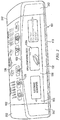
Fig. 2 shows a schematic drawing of the apparatus ofFig. 1 standing in a second operating position with a first appearance according to an example embodiment. Visible is thesecond surface 102 providing thesecond display 120. In this example, thesecond display 120 is a touch display, but other display types are possible. - Visible is also the
third surface 103 providing thethird display 130. In this example, thethird display 130 is a touch display, but other display types are possible. - The border area surrounding the edge or
border 123 between thesecond surface 102 and thethird surface 103 may provide a gap between the second and the third displays 120 and 130, or alternatively, there is no gap between thesecond display 120 and thethird display 130. In the latter case thesecond display 120 forms a bigger display together with thethird display 130, wherein the formed display extends over the edge orborder 123 between thesecond surface 102 and thethird surface 103. In either case, thesecond display 120 and thethird display 130 can be operated independently or dependently of each other. An example of the dependent case has been described in the foregoing (part of an electronic newspaper shown on one display and the next part on the other display). - In the independent case displays can be used for mutually different purposes, such as shown in the example of
Fig. 2 , where thesecond display 120 shows afirst information content 125, such as the user's phonebook contacts, and a calendar, and the third display shows asecond information content 135a, such as icons or links to interesting applications. - The second and third surfaces 102-103 are mainly covered by the second and
third displays second display 120 covers the wholesecond surface 102, and thethird display 130 covers the wholethird surface 103. In other example embodiments, the second and third surfaces 102-103 can, in addition to the second andthird displays third display Fig. 2 shows such a border areas on the left and right sides of the second andthird displays border areas Fig. 2 is theborder area 132 on the bottom side of thethird display 103. On such border areas can be located for example a microphone, certain buttons, additional display elements, indicator lights, or similar. - In certain example embodiments, the apparatus provides the user with the function of controlling, from one of the displays, information content in another one of the displays. In certain example embodiments, the apparatus is configured so that the user can transfer information from one of the displays to another one of the displays, for example, by dragging or clicking. For example, the user can, depending on the implementation, drag by using her/his finger or a stylus an electronic newspaper icon or minimized view from the
third display 130 to thefirst display 110 whereby the newspaper opens in a readable format on thefirst display 110. In certain example embodiments, the user can drag by using her/his finger or a stylus an icon or link towards thesecond display 120 whereby the link or the application associated with the icon opens in thesecond display 120. Alternatively, the same functions can in certain example embodiments be achieved in other ways, such as by a click scheme (such as a double or triple click). - In certain example embodiments, the apparatus is configured to provide the user with different appearances. In certain example embodiments, the apparatus is configured so that the user can customize the appearance of the apparatus according to her/his own preferences. Via operating one or more of the
displays particular display Fig. 3 shows anappearance 135b of thethird display 130 constantly showing radio and time information. -
Fig. 4 shows an example block diagram of anapparatus 400 according to certain example embodiments of the invention. Theapparatus 400 is suitable for functioning as theapparatus 100 described in the foregoing. - The
apparatus 400 comprises at least onenon-volatile memory 450 configured to store computer programs or software comprisingcomputer program code 460. Theapparatus 400 further comprises at least oneprocessor 410 for controlling the operation of theapparatus 400 using thecomputer program code 460, awork memory 420 for running thecomputer program code 460 by the at least oneprocessor 410, and an input/output system (or communication unit) 490 for communicating with other entities or apparatuses. Theapparatus 400 comprises auser interface 470 including at least the displays described in the foregoing. The apparatus further comprises asensing system 480 in connection with the displays. Thesensing system 480 senses or detects touches, clicking, and finger or stylus movements on the displays in the manner known us such to the skilled person. In certain example embodiments, the user does not even have to touch the display, but a mere movement near the display is sensed. Thesensing system 480 is connected to the at least oneprocessor 410. The at least oneprocessor 410 can control the operation of thesensing system 480 in accordance with theprogram code 460. - The at least one
processor 410 may be a master control unit (MCU). Alternatively, the at least oneprocessor 410 may be a microprocessor, a digital signal processor (DSP), an application specific integrated circuit (ASIC), a field programmable gate array, a microcontroller or a combination of such elements. - The
apparatus 400 is generally operated by the at least oneprocessor 410 based on theprogram code 460. As to the operations of the embodiments of the invention, when thecomputer program code 460 is executed by the at least oneprocessor 410, and the at least oneprocessor 410 receives from the sensing means 480 input indicative of touches on one or more displays, this causes theapparatus 400 to implement operations in different embodiments. These operations can, among other things, comprise controlling content or information on one or more of the displays of the generally triangle shaped apparatus based on a detected touch action or detected touch actions, and other operations as described or referenced in the foregoing.
Claims (18)
- An electronic apparatus (100) comprising:a first surface (101) having at least one electronic display (110);a second surface (102) having at least one electronic display (120); anda third surface (103) ; whereinsaid first (101), second (102) and third (103) surface form an outer surface of the apparatus in such a way that a cross section of the apparatus formed by said three surfaces (101, 102, 103) generally resembles a triangle; characterized in that said displays (110,120) form one continuous bigger display, wherein the formed display extends over at least one border (113) between the first (101) and second (102) surface.
- An apparatus according to claim 1, wherein the third surface (103) comprises at least one display (130).
- An apparatus according to claim 1 or 2, wherein at least one of the first (101), second (102) and third (103) surfaces is substantially planar.
- An apparatus according to claim 1 or 2, wherein at least one other of the first (101), second (102) and third (103) surfaces is either convex or concave.
- An apparatus according to any preceding claim, wherein at least one of the first (101), second (102) and third (103) surfaces is bigger than the other surfaces, and wherein that surface is substantially planar providing a planar display.
- An apparatus according to any preceding claim, wherein at least one of the displays (110,120,130) is a touch display.
- An apparatus according to claim 1 or 2, wherein the apparatus is configured to show same content in at least two of the displays (110,120,130).
- An apparatus according to any preceding claim, wherein the apparatus is configured to show a first part of a content in one of the displays (110,120,130) and a second part of the content in another one of the displays (110,120,130).
- An apparatus according to any preceding claim, wherein the apparatus is configured to show an icon or a link to a content in one of the displays (110,120,130) and to show or activate the content in another one of the displays (110,120,130) from the icon or link.
- An apparatus according to claim 9, wherein the apparatus is configured to activate the content in another one of the displays (110,120,130) in response to the icon or link being dragged by a user towards said another one of the displays (110,120,130).
- An apparatus according to claim 9 or 10, wherein the apparatus is configured to show an icon or a link to a content in one of the displays (110,120,130) and to show or activate the content in another one of the displays in response to the icon or link being clicked by a user.
- An apparatus according to any preceding claim, wherein the apparatus is configured to transfer information between the displays (110,120,130) as controlled by a user.
- An apparatus according to any preceding claim, wherein the apparatus is configured to provide a user with a function in which the user drags information from one of the displays (110,120,130) to another one of the displays (110,120,130).
- An apparatus according to any of the claims 1 to 6 or 8 to 13, wherein the displays (110,120,130) are configured to operate independently and the apparatus is configured to show different content on each of the displays (110,120,130).
- An apparatus according to any preceding claim, wherein the apparatus is configured to provide a user with a function of changing the information content or appearance of each of the displays (110,120,130).
- An apparatus according to any of the claims 2-15, wherein at least two of said displays form one continuous bigger display, wherein the formed display extends over at least one border (112, 113, 123) between two of the first (101), second (102) and third (103) surfaces.
- An apparatus according to any preceding claim, wherein the first (101), second (102) and third (103) surfaces are mostly covered by the displays (110,120,130).
- An apparatus according to any preceding claim, wherein the apparatus (100) is a mobile handheld electronic device.
Applications Claiming Priority (2)
| Application Number | Priority Date | Filing Date | Title |
|---|---|---|---|
| US12/645,109 US8638302B2 (en) | 2009-12-22 | 2009-12-22 | Apparatus with multiple displays |
| PCT/FI2010/050768 WO2011076980A1 (en) | 2009-12-22 | 2010-10-04 | Apparatus with multiple displays |
Publications (3)
| Publication Number | Publication Date |
|---|---|
| EP2517445A1 EP2517445A1 (en) | 2012-10-31 |
| EP2517445A4 EP2517445A4 (en) | 2013-03-06 |
| EP2517445B1 true EP2517445B1 (en) | 2016-03-30 |
Family
ID=44150319
Family Applications (1)
| Application Number | Title | Priority Date | Filing Date |
|---|---|---|---|
| EP10838730.9A Not-in-force EP2517445B1 (en) | 2009-12-22 | 2010-10-04 | Apparatus with multiple displays |
Country Status (4)
| Country | Link |
|---|---|
| US (1) | US8638302B2 (en) |
| EP (1) | EP2517445B1 (en) |
| CN (1) | CN102687490B (en) |
| WO (1) | WO2011076980A1 (en) |
Families Citing this family (14)
| Publication number | Priority date | Publication date | Assignee | Title |
|---|---|---|---|---|
| US8599158B2 (en) * | 2011-06-29 | 2013-12-03 | Nokia Corporation | Multi-surface touch sensitive apparatus and method |
| US9432611B1 (en) | 2011-09-29 | 2016-08-30 | Rockwell Collins, Inc. | Voice radio tuning |
| US9922651B1 (en) * | 2014-08-13 | 2018-03-20 | Rockwell Collins, Inc. | Avionics text entry, cursor control, and display format selection via voice recognition |
| KR101515629B1 (en) | 2012-01-07 | 2015-04-27 | 삼성전자주식회사 | Method and apparatus for providing event of portable device having flexible display unit |
| EP2851772B1 (en) * | 2012-05-14 | 2019-02-27 | NEC Corporation | Display device, display control method and non-temporary computer-readable medium |
| US8994678B2 (en) * | 2012-07-18 | 2015-03-31 | Samsung Electronics Co., Ltd. | Techniques for programmable button on bezel of mobile terminal |
| US20140132481A1 (en) * | 2012-11-09 | 2014-05-15 | Microsoft Corporation | Mobile devices with plural displays |
| KR101801554B1 (en) * | 2013-07-11 | 2017-11-27 | 삼성전자주식회사 | User terminal device for displaying contents and methods thereof |
| KR101504236B1 (en) | 2013-07-23 | 2015-03-19 | 엘지전자 주식회사 | Mobile terminal |
| KR20150011942A (en) * | 2013-07-24 | 2015-02-03 | 삼성디스플레이 주식회사 | Electronic device and method of operating the same |
| CN104360709A (en) * | 2014-10-13 | 2015-02-18 | 联想(北京)有限公司 | Electronic equipment and information processing method |
| CN105630076A (en) * | 2014-10-30 | 2016-06-01 | 王澄熙 | Double-screen electronic device |
| KR102308645B1 (en) * | 2014-12-29 | 2021-10-05 | 삼성전자주식회사 | User termincal device and methods for controlling the user termincal device thereof |
| KR102427833B1 (en) | 2015-11-30 | 2022-08-02 | 삼성전자주식회사 | User terminal device and method for display thereof |
Citations (1)
| Publication number | Priority date | Publication date | Assignee | Title |
|---|---|---|---|---|
| US20090256780A1 (en) * | 2008-04-11 | 2009-10-15 | Andrea Small | Digital display devices having communication capabilities |
Family Cites Families (14)
| Publication number | Priority date | Publication date | Assignee | Title |
|---|---|---|---|---|
| FI19991780A7 (en) * | 1999-08-20 | 2001-03-14 | Nokia Corp | Electronic device shell |
| JP2003229935A (en) * | 2002-02-01 | 2003-08-15 | Sony Corp | Portable electronic devices |
| CN100385475C (en) * | 2002-12-27 | 2008-04-30 | 株式会社半导体能源研究所 | Display device and electronic equipment |
| US20040214610A1 (en) * | 2003-04-24 | 2004-10-28 | Tetsuo Tanemura | Communication device having multiple displays |
| US7948448B2 (en) * | 2004-04-01 | 2011-05-24 | Polyvision Corporation | Portable presentation system and methods for use therewith |
| US20050237699A1 (en) * | 2004-04-21 | 2005-10-27 | David Carroll | Multi-screen mobile computing system |
| WO2006045987A1 (en) | 2004-10-28 | 2006-05-04 | Nokia Corporation | Foldable electronic device |
| WO2007098141A2 (en) | 2006-02-18 | 2007-08-30 | Cattail Group, Inc. | Electronic apparatus with multiple discrete interface surfaces |
| GB0708432D0 (en) | 2007-05-01 | 2007-06-06 | Four Way Innovations Ltd | Configurable electronic device |
| US20080311958A1 (en) * | 2007-06-15 | 2008-12-18 | Motorola, Inc. | Twist electronic device and methods therefor |
| US7545627B1 (en) * | 2007-11-24 | 2009-06-09 | Lantigua Juan J | Lapdesk dual interface portable-stationary computer |
| KR101474754B1 (en) * | 2008-01-30 | 2014-12-19 | 삼성전자주식회사 | Portable information terminal |
| KR101463819B1 (en) * | 2008-05-14 | 2014-12-04 | 엘지전자 주식회사 | Portable terminal |
| US20100156887A1 (en) * | 2008-12-18 | 2010-06-24 | Nokia Corporation | Extended user interface |
-
2009
- 2009-12-22 US US12/645,109 patent/US8638302B2/en not_active Expired - Fee Related
-
2010
- 2010-10-04 EP EP10838730.9A patent/EP2517445B1/en not_active Not-in-force
- 2010-10-04 WO PCT/FI2010/050768 patent/WO2011076980A1/en not_active Ceased
- 2010-10-04 CN CN201080059019.3A patent/CN102687490B/en not_active Expired - Fee Related
Patent Citations (1)
| Publication number | Priority date | Publication date | Assignee | Title |
|---|---|---|---|---|
| US20090256780A1 (en) * | 2008-04-11 | 2009-10-15 | Andrea Small | Digital display devices having communication capabilities |
Also Published As
| Publication number | Publication date |
|---|---|
| US20110148772A1 (en) | 2011-06-23 |
| CN102687490A (en) | 2012-09-19 |
| CN102687490B (en) | 2015-03-11 |
| EP2517445A4 (en) | 2013-03-06 |
| EP2517445A1 (en) | 2012-10-31 |
| WO2011076980A1 (en) | 2011-06-30 |
| US8638302B2 (en) | 2014-01-28 |
Similar Documents
| Publication | Publication Date | Title |
|---|---|---|
| US8638302B2 (en) | Apparatus with multiple displays | |
| US8195254B2 (en) | Apparatus comprising a sliding display part | |
| JP5734546B2 (en) | Object display device | |
| US10114485B2 (en) | Keyboard and touchpad areas | |
| CN101984384B (en) | Mobile terminal and design method of operation and control technology thereof | |
| TWI360061B (en) | Electronic device and method for operating applica | |
| TWI520047B (en) | Touch bar and mobile terminal device | |
| CN101910983B (en) | Wireless communication device and split touch sensitive user input surface | |
| US20120127093A1 (en) | Touch pad and electronic display device applied with the same | |
| WO2021143805A1 (en) | Widget processing method and related apparatus | |
| CN102402389A (en) | Touch display device and control method thereof | |
| CN101252607A (en) | Slider phone with extended display | |
| JP3200386U (en) | Touch display device | |
| CN101482790A (en) | Electronic device capable of transferring objects on two display elements and control method thereof | |
| US20160231772A1 (en) | Wearable electronic device and touch operation method | |
| CN104035606A (en) | Operation method and electronic device of touch panel | |
| US20120274600A1 (en) | Portable Electronic Device and Method for Controlling the Same | |
| US20160026309A1 (en) | Controller | |
| TW200823721A (en) | Notebook computer capable of preventing its touch panel from being touched accidentally | |
| TWM382526U (en) | External input device | |
| CN101598987B (en) | Configuration pointing operation device and computer system | |
| CN102023789A (en) | Data selection method and system | |
| TWI823221B (en) | Mouse device having a button arranged a plurality of touch zones | |
| RU96671U1 (en) | UNIVERSAL DEVICE FOR ENTERING INFORMATION IN A PERSONAL COMPUTER (OPTIONS) | |
| US20160026325A1 (en) | Hand-held electronic device, touch-sensing cover and computer-executed method |
Legal Events
| Date | Code | Title | Description |
|---|---|---|---|
| PUAI | Public reference made under article 153(3) epc to a published international application that has entered the european phase |
Free format text: ORIGINAL CODE: 0009012 |
|
| 17P | Request for examination filed |
Effective date: 20120608 |
|
| AK | Designated contracting states |
Kind code of ref document: A1 Designated state(s): AL AT BE BG CH CY CZ DE DK EE ES FI FR GB GR HR HU IE IS IT LI LT LU LV MC MK MT NL NO PL PT RO RS SE SI SK SM TR |
|
| A4 | Supplementary search report drawn up and despatched |
Effective date: 20130201 |
|
| RIC1 | Information provided on ipc code assigned before grant |
Ipc: G06F 1/16 20060101ALI20130128BHEP Ipc: H04M 1/02 20060101AFI20130128BHEP |
|
| DAX | Request for extension of the european patent (deleted) | ||
| RAP1 | Party data changed (applicant data changed or rights of an application transferred) |
Owner name: NOKIA CORPORATION |
|
| 17Q | First examination report despatched |
Effective date: 20141217 |
|
| RAP1 | Party data changed (applicant data changed or rights of an application transferred) |
Owner name: NOKIA TECHNOLOGIES OY |
|
| GRAP | Despatch of communication of intention to grant a patent |
Free format text: ORIGINAL CODE: EPIDOSNIGR1 |
|
| INTG | Intention to grant announced |
Effective date: 20151016 |
|
| GRAS | Grant fee paid |
Free format text: ORIGINAL CODE: EPIDOSNIGR3 |
|
| GRAA | (expected) grant |
Free format text: ORIGINAL CODE: 0009210 |
|
| AK | Designated contracting states |
Kind code of ref document: B1 Designated state(s): AL AT BE BG CH CY CZ DE DK EE ES FI FR GB GR HR HU IE IS IT LI LT LU LV MC MK MT NL NO PL PT RO RS SE SI SK SM TR |
|
| REG | Reference to a national code |
Ref country code: GB Ref legal event code: FG4D |
|
| REG | Reference to a national code |
Ref country code: CH Ref legal event code: EP |
|
| REG | Reference to a national code |
Ref country code: AT Ref legal event code: REF Ref document number: 786505 Country of ref document: AT Kind code of ref document: T Effective date: 20160415 |
|
| REG | Reference to a national code |
Ref country code: IE Ref legal event code: FG4D |
|
| REG | Reference to a national code |
Ref country code: DE Ref legal event code: R096 Ref document number: 602010031920 Country of ref document: DE |
|
| REG | Reference to a national code |
Ref country code: LT Ref legal event code: MG4D |
|
| PG25 | Lapsed in a contracting state [announced via postgrant information from national office to epo] |
Ref country code: FI Free format text: LAPSE BECAUSE OF FAILURE TO SUBMIT A TRANSLATION OF THE DESCRIPTION OR TO PAY THE FEE WITHIN THE PRESCRIBED TIME-LIMIT Effective date: 20160330 Ref country code: HR Free format text: LAPSE BECAUSE OF FAILURE TO SUBMIT A TRANSLATION OF THE DESCRIPTION OR TO PAY THE FEE WITHIN THE PRESCRIBED TIME-LIMIT Effective date: 20160330 Ref country code: GR Free format text: LAPSE BECAUSE OF FAILURE TO SUBMIT A TRANSLATION OF THE DESCRIPTION OR TO PAY THE FEE WITHIN THE PRESCRIBED TIME-LIMIT Effective date: 20160701 Ref country code: NO Free format text: LAPSE BECAUSE OF FAILURE TO SUBMIT A TRANSLATION OF THE DESCRIPTION OR TO PAY THE FEE WITHIN THE PRESCRIBED TIME-LIMIT Effective date: 20160630 |
|
| REG | Reference to a national code |
Ref country code: NL Ref legal event code: MP Effective date: 20160330 |
|
| REG | Reference to a national code |
Ref country code: AT Ref legal event code: MK05 Ref document number: 786505 Country of ref document: AT Kind code of ref document: T Effective date: 20160330 |
|
| PG25 | Lapsed in a contracting state [announced via postgrant information from national office to epo] |
Ref country code: LT Free format text: LAPSE BECAUSE OF FAILURE TO SUBMIT A TRANSLATION OF THE DESCRIPTION OR TO PAY THE FEE WITHIN THE PRESCRIBED TIME-LIMIT Effective date: 20160330 Ref country code: RS Free format text: LAPSE BECAUSE OF FAILURE TO SUBMIT A TRANSLATION OF THE DESCRIPTION OR TO PAY THE FEE WITHIN THE PRESCRIBED TIME-LIMIT Effective date: 20160330 Ref country code: LV Free format text: LAPSE BECAUSE OF FAILURE TO SUBMIT A TRANSLATION OF THE DESCRIPTION OR TO PAY THE FEE WITHIN THE PRESCRIBED TIME-LIMIT Effective date: 20160330 Ref country code: SE Free format text: LAPSE BECAUSE OF FAILURE TO SUBMIT A TRANSLATION OF THE DESCRIPTION OR TO PAY THE FEE WITHIN THE PRESCRIBED TIME-LIMIT Effective date: 20160330 |
|
| PG25 | Lapsed in a contracting state [announced via postgrant information from national office to epo] |
Ref country code: NL Free format text: LAPSE BECAUSE OF FAILURE TO SUBMIT A TRANSLATION OF THE DESCRIPTION OR TO PAY THE FEE WITHIN THE PRESCRIBED TIME-LIMIT Effective date: 20160330 |
|
| PG25 | Lapsed in a contracting state [announced via postgrant information from national office to epo] |
Ref country code: EE Free format text: LAPSE BECAUSE OF FAILURE TO SUBMIT A TRANSLATION OF THE DESCRIPTION OR TO PAY THE FEE WITHIN THE PRESCRIBED TIME-LIMIT Effective date: 20160330 Ref country code: IS Free format text: LAPSE BECAUSE OF FAILURE TO SUBMIT A TRANSLATION OF THE DESCRIPTION OR TO PAY THE FEE WITHIN THE PRESCRIBED TIME-LIMIT Effective date: 20160730 Ref country code: PL Free format text: LAPSE BECAUSE OF FAILURE TO SUBMIT A TRANSLATION OF THE DESCRIPTION OR TO PAY THE FEE WITHIN THE PRESCRIBED TIME-LIMIT Effective date: 20160330 |
|
| PG25 | Lapsed in a contracting state [announced via postgrant information from national office to epo] |
Ref country code: AT Free format text: LAPSE BECAUSE OF FAILURE TO SUBMIT A TRANSLATION OF THE DESCRIPTION OR TO PAY THE FEE WITHIN THE PRESCRIBED TIME-LIMIT Effective date: 20160330 Ref country code: SK Free format text: LAPSE BECAUSE OF FAILURE TO SUBMIT A TRANSLATION OF THE DESCRIPTION OR TO PAY THE FEE WITHIN THE PRESCRIBED TIME-LIMIT Effective date: 20160330 Ref country code: ES Free format text: LAPSE BECAUSE OF FAILURE TO SUBMIT A TRANSLATION OF THE DESCRIPTION OR TO PAY THE FEE WITHIN THE PRESCRIBED TIME-LIMIT Effective date: 20160330 Ref country code: SM Free format text: LAPSE BECAUSE OF FAILURE TO SUBMIT A TRANSLATION OF THE DESCRIPTION OR TO PAY THE FEE WITHIN THE PRESCRIBED TIME-LIMIT Effective date: 20160330 Ref country code: CZ Free format text: LAPSE BECAUSE OF FAILURE TO SUBMIT A TRANSLATION OF THE DESCRIPTION OR TO PAY THE FEE WITHIN THE PRESCRIBED TIME-LIMIT Effective date: 20160330 Ref country code: RO Free format text: LAPSE BECAUSE OF FAILURE TO SUBMIT A TRANSLATION OF THE DESCRIPTION OR TO PAY THE FEE WITHIN THE PRESCRIBED TIME-LIMIT Effective date: 20160330 Ref country code: PT Free format text: LAPSE BECAUSE OF FAILURE TO SUBMIT A TRANSLATION OF THE DESCRIPTION OR TO PAY THE FEE WITHIN THE PRESCRIBED TIME-LIMIT Effective date: 20160801 |
|
| PG25 | Lapsed in a contracting state [announced via postgrant information from national office to epo] |
Ref country code: BE Free format text: LAPSE BECAUSE OF FAILURE TO SUBMIT A TRANSLATION OF THE DESCRIPTION OR TO PAY THE FEE WITHIN THE PRESCRIBED TIME-LIMIT Effective date: 20160330 Ref country code: IT Free format text: LAPSE BECAUSE OF FAILURE TO SUBMIT A TRANSLATION OF THE DESCRIPTION OR TO PAY THE FEE WITHIN THE PRESCRIBED TIME-LIMIT Effective date: 20160330 |
|
| REG | Reference to a national code |
Ref country code: DE Ref legal event code: R097 Ref document number: 602010031920 Country of ref document: DE |
|
| PG25 | Lapsed in a contracting state [announced via postgrant information from national office to epo] |
Ref country code: DK Free format text: LAPSE BECAUSE OF FAILURE TO SUBMIT A TRANSLATION OF THE DESCRIPTION OR TO PAY THE FEE WITHIN THE PRESCRIBED TIME-LIMIT Effective date: 20160330 |
|
| PLBE | No opposition filed within time limit |
Free format text: ORIGINAL CODE: 0009261 |
|
| STAA | Information on the status of an ep patent application or granted ep patent |
Free format text: STATUS: NO OPPOSITION FILED WITHIN TIME LIMIT |
|
| 26N | No opposition filed |
Effective date: 20170103 |
|
| PG25 | Lapsed in a contracting state [announced via postgrant information from national office to epo] |
Ref country code: SI Free format text: LAPSE BECAUSE OF FAILURE TO SUBMIT A TRANSLATION OF THE DESCRIPTION OR TO PAY THE FEE WITHIN THE PRESCRIBED TIME-LIMIT Effective date: 20160330 |
|
| REG | Reference to a national code |
Ref country code: CH Ref legal event code: PL |
|
| GBPC | Gb: european patent ceased through non-payment of renewal fee |
Effective date: 20161004 |
|
| REG | Reference to a national code |
Ref country code: IE Ref legal event code: MM4A |
|
| REG | Reference to a national code |
Ref country code: FR Ref legal event code: ST Effective date: 20170630 |
|
| PG25 | Lapsed in a contracting state [announced via postgrant information from national office to epo] |
Ref country code: LI Free format text: LAPSE BECAUSE OF NON-PAYMENT OF DUE FEES Effective date: 20161031 Ref country code: GB Free format text: LAPSE BECAUSE OF NON-PAYMENT OF DUE FEES Effective date: 20161004 Ref country code: CH Free format text: LAPSE BECAUSE OF NON-PAYMENT OF DUE FEES Effective date: 20161031 Ref country code: FR Free format text: LAPSE BECAUSE OF NON-PAYMENT OF DUE FEES Effective date: 20161102 |
|
| PG25 | Lapsed in a contracting state [announced via postgrant information from national office to epo] |
Ref country code: LU Free format text: LAPSE BECAUSE OF NON-PAYMENT OF DUE FEES Effective date: 20161004 |
|
| PG25 | Lapsed in a contracting state [announced via postgrant information from national office to epo] |
Ref country code: IE Free format text: LAPSE BECAUSE OF NON-PAYMENT OF DUE FEES Effective date: 20161004 |
|
| PGFP | Annual fee paid to national office [announced via postgrant information from national office to epo] |
Ref country code: DE Payment date: 20170927 Year of fee payment: 8 |
|
| PG25 | Lapsed in a contracting state [announced via postgrant information from national office to epo] |
Ref country code: CY Free format text: LAPSE BECAUSE OF FAILURE TO SUBMIT A TRANSLATION OF THE DESCRIPTION OR TO PAY THE FEE WITHIN THE PRESCRIBED TIME-LIMIT Effective date: 20160330 Ref country code: HU Free format text: LAPSE BECAUSE OF FAILURE TO SUBMIT A TRANSLATION OF THE DESCRIPTION OR TO PAY THE FEE WITHIN THE PRESCRIBED TIME-LIMIT; INVALID AB INITIO Effective date: 20101004 |
|
| PG25 | Lapsed in a contracting state [announced via postgrant information from national office to epo] |
Ref country code: MK Free format text: LAPSE BECAUSE OF FAILURE TO SUBMIT A TRANSLATION OF THE DESCRIPTION OR TO PAY THE FEE WITHIN THE PRESCRIBED TIME-LIMIT Effective date: 20160330 Ref country code: TR Free format text: LAPSE BECAUSE OF FAILURE TO SUBMIT A TRANSLATION OF THE DESCRIPTION OR TO PAY THE FEE WITHIN THE PRESCRIBED TIME-LIMIT Effective date: 20160330 Ref country code: MT Free format text: LAPSE BECAUSE OF NON-PAYMENT OF DUE FEES Effective date: 20161031 Ref country code: MC Free format text: LAPSE BECAUSE OF FAILURE TO SUBMIT A TRANSLATION OF THE DESCRIPTION OR TO PAY THE FEE WITHIN THE PRESCRIBED TIME-LIMIT Effective date: 20160330 |
|
| PG25 | Lapsed in a contracting state [announced via postgrant information from national office to epo] |
Ref country code: BG Free format text: LAPSE BECAUSE OF FAILURE TO SUBMIT A TRANSLATION OF THE DESCRIPTION OR TO PAY THE FEE WITHIN THE PRESCRIBED TIME-LIMIT Effective date: 20160330 |
|
| PG25 | Lapsed in a contracting state [announced via postgrant information from national office to epo] |
Ref country code: AL Free format text: LAPSE BECAUSE OF FAILURE TO SUBMIT A TRANSLATION OF THE DESCRIPTION OR TO PAY THE FEE WITHIN THE PRESCRIBED TIME-LIMIT Effective date: 20160330 |
|
| REG | Reference to a national code |
Ref country code: DE Ref legal event code: R081 Ref document number: 602010031920 Country of ref document: DE Owner name: PROVENANCE ASSET GROUP LLC, PITTSFORD, US Free format text: FORMER OWNER: NOKIA TECHNOLOGIES OY, ESPOO, FI |
|
| REG | Reference to a national code |
Ref country code: DE Ref legal event code: R119 Ref document number: 602010031920 Country of ref document: DE |
|
| PG25 | Lapsed in a contracting state [announced via postgrant information from national office to epo] |
Ref country code: DE Free format text: LAPSE BECAUSE OF NON-PAYMENT OF DUE FEES Effective date: 20190501 |