EP2517327B1 - Battery energy storage system with short circuit protection, and method - Google Patents
Battery energy storage system with short circuit protection, and method Download PDFInfo
- Publication number
- EP2517327B1 EP2517327B1 EP20090799634 EP09799634A EP2517327B1 EP 2517327 B1 EP2517327 B1 EP 2517327B1 EP 20090799634 EP20090799634 EP 20090799634 EP 09799634 A EP09799634 A EP 09799634A EP 2517327 B1 EP2517327 B1 EP 2517327B1
- Authority
- EP
- European Patent Office
- Prior art keywords
- battery
- energy storage
- storage system
- stack
- semiconductor switch
- Prior art date
- Legal status (The legal status is an assumption and is not a legal conclusion. Google has not performed a legal analysis and makes no representation as to the accuracy of the status listed.)
- Active
Links
Images


Classifications
-
- H—ELECTRICITY
- H02—GENERATION; CONVERSION OR DISTRIBUTION OF ELECTRIC POWER
- H02H—EMERGENCY PROTECTIVE CIRCUIT ARRANGEMENTS
- H02H7/00—Emergency protective circuit arrangements specially adapted for specific types of electric machines or apparatus or for sectionalised protection of cable or line systems, and effecting automatic switching in the event of an undesired change from normal working conditions
- H02H7/18—Emergency protective circuit arrangements specially adapted for specific types of electric machines or apparatus or for sectionalised protection of cable or line systems, and effecting automatic switching in the event of an undesired change from normal working conditions for batteries; for accumulators
-
- H—ELECTRICITY
- H02—GENERATION; CONVERSION OR DISTRIBUTION OF ELECTRIC POWER
- H02J—ELECTRIC POWER NETWORKS; CIRCUIT ARRANGEMENTS OR SYSTEMS FOR SUPPLYING OR DISTRIBUTING ELECTRIC POWER; SYSTEMS FOR STORING ELECTRIC ENERGY
- H02J7/00—Circuit arrangements for charging or discharging batteries or for supplying loads from batteries
- H02J7/60—Circuit arrangements for charging or discharging batteries or for supplying loads from batteries including safety or protection arrangements
- H02J7/663—Circuit arrangements for charging or discharging batteries or for supplying loads from batteries including safety or protection arrangements using battery or load disconnect circuits
-
- H—ELECTRICITY
- H01—ELECTRIC ELEMENTS
- H01M—PROCESSES OR MEANS, e.g. BATTERIES, FOR THE DIRECT CONVERSION OF CHEMICAL ENERGY INTO ELECTRICAL ENERGY
- H01M10/00—Secondary cells; Manufacture thereof
-
- H—ELECTRICITY
- H01—ELECTRIC ELEMENTS
- H01M—PROCESSES OR MEANS, e.g. BATTERIES, FOR THE DIRECT CONVERSION OF CHEMICAL ENERGY INTO ELECTRICAL ENERGY
- H01M10/00—Secondary cells; Manufacture thereof
- H01M10/42—Methods or arrangements for servicing or maintenance of secondary cells or secondary half-cells
-
- H—ELECTRICITY
- H02—GENERATION; CONVERSION OR DISTRIBUTION OF ELECTRIC POWER
- H02J—ELECTRIC POWER NETWORKS; CIRCUIT ARRANGEMENTS OR SYSTEMS FOR SUPPLYING OR DISTRIBUTING ELECTRIC POWER; SYSTEMS FOR STORING ELECTRIC ENERGY
- H02J7/00—Circuit arrangements for charging or discharging batteries or for supplying loads from batteries
- H02J7/50—Circuit arrangements for charging or discharging batteries or for supplying loads from batteries acting upon multiple batteries simultaneously or sequentially
- H02J7/52—Circuit arrangements for charging or discharging batteries or for supplying loads from batteries acting upon multiple batteries simultaneously or sequentially for charge balancing, e.g. equalisation of charge between batteries
Definitions
- the invention relates generally to the field of electric power transmission systems, and in particular to battery storages for use in such power systems.
- electric power transmission systems is meant a distribution system of at least 3 kV, preferably at least 10kV.
- Electric power systems need to provide electric power in a reliable fashion. Therefore such systems often comprise backup devices, for example in form of DC power sources.
- the backup devices may provide power for evening out fluctuations, shortages etc.
- the battery energy storage 10 comprises a number of series- and/or parallel-connected battery cells arranged in battery modules 20.
- the battery modules 20 in turn are series- and/or parallel-connected to form a battery unit 30 and several battery units 30 may be series-connected to form a battery string 40.
- several such battery strings 40 are connected in parallel between negative and positive busbars.
- the battery strings 40 are connected to a load, for example a converter system 50, which in turn is connected to a power network transmission system.
- Circuit breakers 60 may further be arranged between each battery string and the respective DC busbars.
- WO2008/002223 A1 describes a power compensator (see abstract) for an AC electric power transmission.
- the power compensator comprises a voltage source converter (4 in the figure) connected to a capacitor means (6) in parallel with a DC energy storage device (5).
- the energy storage device (5) comprises a high voltage battery means, including a battery string, having a short circuit failure mode, a first (40a) switch and a second switch (40b) for disconnecting the battery string, and a control unit (44) for operating these switches (40a, 40b).
- US 5773962 A discloses an energy monitoring system for use in a battery power vehicle. Batteries are connected in a long series and can be bypassed upon detection of a fault condition An example can be seen in figure 2 . The cells are bypassed to ensure that they are not overcharged or over discharged.
- US 2009/310270 A1 is directed towards a short circuit protection scheme in which a battery supplies a load in which the drawing of current can be initiated very quickly and then resets itself in the event of a detected short circuit.
- the short circuit is detected by measuring the voltage at the load side of a switch.
- a battery energy storage system comprising strings of battery units in series.
- Each battery unit comprises at least one battery module including a plurality of battery cells and a semiconductor switch, which battery module is connected in series with the semiconductor switch.
- the storage system includes a control unit that controls the semiconductor switch, so that large currents, for example from short circuits, are prevented from damaging the battery cells of the battery module. Thus, each battery module is protected by its semiconductor switch.
- a large battery energy storage comprises many battery units and these battery units in turn comprises one or preferably more than one battery module, each battery module electrically connected in a serial circuit with a semiconductor switch, and wherein the battery module circuits preferably are electrically connected in parallel.
- the system includes at least one control unit that manage each battery unit, and the semiconductor switch of each battery module of the battery unit.
- the system makes it possible to turn off internal short circuit currents of a battery string, each semiconductor switch disconnects only one battery module, and every battery module is directly connected in series with its own semiconductor switch without any battery modules in-between.
- the battery unit preferably includes a battery control unit for controlling the semiconductor switch of every battery module.
- the battery unit includes a plurality of battery modules arranged in parallel and each semiconductor switch is controlled by the system to protect each battery module.
- the battery units are arranged in battery stacks, wherein a plurality of battery units are connected in series.
- the battery stack includes a stack controller that controls the battery units so that disconnection of the battery modules of the stack is synchronised. In this way all battery modules of the stack are disconnected simultaneously.
- a simultaneous disconnection of the battery modules of a stack is controlled by the battery control units of the battery units, wherein the battery control units are adapted to instruct the other battery control units to disconnect their modules when the battery unit disconnects its own batter modules.
- the energy storage system further comprises a system controller connected to the battery control unit and the system controller is arranged and adapted to control the energy storage system, including balancing the state-of charge of the battery units by controlling the current from the different battery units, and monitoring the overall functioning of the energy storage system, for example by being adapted to control the system alone or in combination with the battery control units and stack control units.
- the semiconductor switch also include a diode arranged in parallel.
- the diode is arranged to conduct during charging only.
- the diode is used to charge the battery cells of the battery modules with excessive power from a transmission system to which the energy storage is connected, such as to the DC side of a voltage source converter.
- each semiconductor switch of the battery modules comprises a MOSFET transistor for the switching.
- the MOSFET transistor comprises an intrinsic diode.
- control unit i.e. the system controller, the stack controller or, preferably, the battery control unit, includes means for monitoring the current, such as a current measuring unit, through each battery module, and is adapted to instruct the semiconductor switch to disconnect the battery module if the current is above a short circuit threshold.
- control unit i.e. the system controller, the stack controller or, preferably, the battery control unit, includes means for continuously monitoring the voltage across the semiconductor switch including the parallel diode, and is adapted to instruct the semiconductor of all switches to simultaneously turn off if the voltage exceeds a certain threshold when the switch is activated (turned on).
- the high voltage is diagnosed as a short circuit through the switch. If the voltage exceeds the threshold during charging then it is an indication that there is an external (external to the module) short circuit and an alarm is sent to the controller.
- the battery module By disconnecting the battery module when the current is too large, the other battery cells of the string or other strings are protected from the malfunctioning battery module, and also the battery modules can be protected from harmful current levels originating from the voltage source converter, or transmission system, to which the energy storage is connected.
- each of the battery control units are adapted to measure the voltage of and/or current through each battery module circuit, e.g. semiconductor switch and/or battery module.
- the battery units can preferably be provided with switches for disconnecting the whole battery unit from the next battery unit in the series of battery units, when the current or voltage is too large.
- the battery control unit or the stack controller can suitable be arranged and adapted to provide the disconnection of these switches.
- each stack controller are adapted to measure the current in, and voltage over, each battery stack.
- Each battery stack is preferably provided with switches for disconnecting it from other battery stacks. These switches can be controlled by the battery stack controller when current or voltage of the stack is too large.
- each battery stack provides DC voltage at 1-10 kV, preferably between 2 and 5 kV or approximately 3 kV, and the string includes at least two stacks.
- the system can be dimensioned for voltages of between 10 kV and 100 kV, or even more than 100 kV.
- each battery unit provides between 50 and 1000 volts, such as more than 100 volts and/or lower than 500 volts, especially between 150 and 350 volts or approximately 250 volts. Twelve 250-volt battery units create a stack of 3 kV.
- Each stack includes preferably more than three battery units, such as more than five or seven units, or more than ten units, such as twelve battery units or more.
- the switches are preferably MOSFET or IGBT (Insulated Gate Bipolar Transistor) switches.
- MOSFET switches are suitable for voltages up to 1000 volt, whereas IGBT switches are suitable above 1000 volts.
- IGBT switches can be used for voltages below 1000 volts as well, especially, IGBT switches are suitable for voltage levels above 200 volts.
- MOSFET switches are used, preferably in the battery units providing between 50 and 1000 volts.
- IGBT switches are used, preferably in battery units providing more than 50 volts, especially more than 200 volts.
- system control unit has means for and is adapted to monitor and measure the currents in each string and/or the voltages across each string of the storage.
- the strings are connected to DC buses by means of switches and the system controller can be adapted to control these switches to provide disconnection of a whole string when currents and/or voltage is too large for the string.
- this object is achieved by a method as defined in claim 15.
- Such a method comprises the following steps:
- Figure 1 illustrates an apparatus for providing power to an AC power transmission system. It includes a capacitor 1 in parallel with a high voltage DC power source 2-4, 6, 7 connected to the DC side of a voltage source converter 5.
- the voltage source converter 5 is connected on its other side to an AC high voltage power transmission system (not illustrated).
- the DC power source comprises an energy storage system having a plurality of parallel strings 4a-c, and each string comprises battery stacks 3a-c connected in series.
- Each string 4a-c are connected to the voltage source converter 5 by common bus bars via a first and second disconnector 6a-f, so that the whole energy storage string can be selectively connected and disconnected from the common DC buses and the voltage source converter 5.
- Each battery stack 3a-c comprises a stack of battery units 2a-c in series and a stack controller 7a-c.
- the stack controller 7a-c are in turn connected to a common system or main control unit 17.
- the number of battery stacks 3a-c in each string is chosen to create the desired voltage level.
- FIG. 2 illustrates the battery stacks (3a-c in figure 1 ) in more detail. Every battery stack 3 includes serially interconnected battery units 2a-c in a stack configuration, and a stack controller 7. The battery stack 3 is connected to a first and a second disconnector 16a-b for selectively connecting the battery stack to other battery stacks, one disconnector in each end.
- Each battery unit 2a-c includes a battery control unit 12a-c and parallel circuits, wherein each parallel circuit includes a battery module 22, with a plurality of battery cells, in serial connection with a semiconductor switch 23.
- Each battery module 22 is connected to its own semiconductor switch 23.
- each battery unit 2 comprises at least one such circuit consisting essentially of a battery module 22 in series with a semiconductor switch.
- the semiconductor switch includes a MOSFET with its intrinsic diode.
- the MOSFET and diode are in opposite directions, i.e. the MOSFET is conducting only during discharging, while the diode only conducts during charging.
- the battery control units 12a-c controls the MOSFETS of every parallel circuit.
- the battery control units 12a-c are preferably daisy chained in a communication link 13, so that they are communicatively connected to each other.
- Each battery control units is also preferably directly connected to the stack controller 7 in a communication link 14.
- the stack controller 7 is suitably adapted to synchronise the switching of all semiconductor switches 23 in the battery stack 3.
- the battery control unit 12a-c When disconnecting a malfunctioning battery module 22, the battery control unit 12a-c is suitably adapted to instruct the other battery control units 12a-c of the communication link 13 to disconnect their respective battery modules 22, so that all battery modules 22 of the stack 3 are disconnected.
- Each battery module 2 also includes a mechanical switch 21 for disconnecting the battery module.
- the switch 21 is arranged in series with the module on the opposite side to the semiconductor switch.
- the stack controllers 7a-c of every battery stack 3a-c of a string is connected to a system control unit 17, which suitably is adapted to synchronise the stack controllers 7a-c to disconnect simultaneously so that all the battery modules of the string are disconnected.
- the battery control unit 12a-c, and/or the other control units (7, 17), can be arranged to, and adapted for, measuring and controlling the battery stacks and for this purpose be provided with means for measuring different parameters such as battery currents, cell- and battery voltages, temperature, battery state-of-charge, and performing cell balancing.
- the battery control units 12a-c can be adapted to handle communication between battery stacks 3a-c and handle communication in order to send and receive data from the stack controller 7 and the system controller 17.
Landscapes
- Engineering & Computer Science (AREA)
- Power Engineering (AREA)
- Manufacturing & Machinery (AREA)
- Chemical & Material Sciences (AREA)
- Chemical Kinetics & Catalysis (AREA)
- Electrochemistry (AREA)
- General Chemical & Material Sciences (AREA)
- Charge And Discharge Circuits For Batteries Or The Like (AREA)
- Secondary Cells (AREA)
Description
- The invention relates generally to the field of electric power transmission systems, and in particular to battery storages for use in such power systems. By electric power transmission systems is meant a distribution system of at least 3 kV, preferably at least 10kV.
- Electric power systems need to provide electric power in a reliable fashion. Therefore such systems often comprise backup devices, for example in form of DC power sources. The backup devices may provide power for evening out fluctuations, shortages etc.
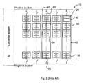
- An example of such a device, usable as a backup, is a battery energy storage as illustrated in
figure 3 . Thebattery energy storage 10 comprises a number of series- and/or parallel-connected battery cells arranged inbattery modules 20. Thebattery modules 20 in turn are series- and/or parallel-connected to form abattery unit 30 andseveral battery units 30 may be series-connected to form abattery string 40. In large battery energy storage systems, severalsuch battery strings 40 are connected in parallel between negative and positive busbars. Thebattery strings 40 are connected to a load, for example aconverter system 50, which in turn is connected to a power network transmission system.Circuit breakers 60 may further be arranged between each battery string and the respective DC busbars. -
WO2008/002223 A1 describes a power compensator (see abstract) for an AC electric power transmission. The power compensator comprises a voltage source converter (4 in the figure) connected to a capacitor means (6) in parallel with a DC energy storage device (5). The energy storage device (5) comprises a high voltage battery means, including a battery string, having a short circuit failure mode, a first (40a) switch and a second switch (40b) for disconnecting the battery string, and a control unit (44) for operating these switches (40a, 40b). -
US 5773962 A discloses an energy monitoring system for use in a battery power vehicle. Batteries are connected in a long series and can be bypassed upon detection of a fault condition An example can be seen infigure 2 . The cells are bypassed to ensure that they are not overcharged or over discharged. -
US 2009/310270 A1 is directed towards a short circuit protection scheme in which a battery supplies a load in which the drawing of current can be initiated very quickly and then resets itself in the event of a detected short circuit. The short circuit is detected by measuring the voltage at the load side of a switch. - A drawback with these short circuit protection switches is that they have to be dimensioned for high voltage, including large space requirements, and must be able to break very large short circuit currents.
- It is an object of the invention to overcome or at least alleviate the above-mentioned problems. In particular, it is an object of the invention to provide improved means for short circuit protection of battery units in energy storage systems.
- These objects, among others, are achieved by a battery energy storage system and by a method as claimed in the appended independent claims.
- In accordance with the invention, a battery energy storage system is provided comprising strings of battery units in series. Each battery unit comprises at least one battery module including a plurality of battery cells and a semiconductor switch, which battery module is connected in series with the semiconductor switch. The storage system includes a control unit that controls the semiconductor switch, so that large currents, for example from short circuits, are prevented from damaging the battery cells of the battery module. Thus, each battery module is protected by its semiconductor switch.
- A large battery energy storage comprises many battery units and these battery units in turn comprises one or preferably more than one battery module, each battery module electrically connected in a serial circuit with a semiconductor switch, and wherein the battery module circuits preferably are electrically connected in parallel. The system includes at least one control unit that manage each battery unit, and the semiconductor switch of each battery module of the battery unit.
- The system makes it possible to turn off internal short circuit currents of a battery string, each semiconductor switch disconnects only one battery module, and every battery module is directly connected in series with its own semiconductor switch without any battery modules in-between.
- The battery unit preferably includes a battery control unit for controlling the semiconductor switch of every battery module.
- In an embodiment, the battery unit includes a plurality of battery modules arranged in parallel and each semiconductor switch is controlled by the system to protect each battery module.
- In an embodiment the battery units are arranged in battery stacks, wherein a plurality of battery units are connected in series.
- Preferably the battery stack includes a stack controller that controls the battery units so that disconnection of the battery modules of the stack is synchronised. In this way all battery modules of the stack are disconnected simultaneously. In another preferred embodiment, a simultaneous disconnection of the battery modules of a stack is controlled by the battery control units of the battery units, wherein the battery control units are adapted to instruct the other battery control units to disconnect their modules when the battery unit disconnects its own batter modules.
- In an embodiment, the energy storage system further comprises a system controller connected to the battery control unit and the system controller is arranged and adapted to control the energy storage system, including balancing the state-of charge of the battery units by controlling the current from the different battery units, and monitoring the overall functioning of the energy storage system, for example by being adapted to control the system alone or in combination with the battery control units and stack control units.
- Preferably, the semiconductor switch also include a diode arranged in parallel. The diode is arranged to conduct during charging only. Thus, the diode is used to charge the battery cells of the battery modules with excessive power from a transmission system to which the energy storage is connected, such as to the DC side of a voltage source converter.
- In an embodiment each semiconductor switch of the battery modules comprises a MOSFET transistor for the switching. The MOSFET transistor comprises an intrinsic diode.
- In an embodiment the control unit, i.e. the system controller, the stack controller or, preferably, the battery control unit, includes means for monitoring the current, such as a current measuring unit, through each battery module, and is adapted to instruct the semiconductor switch to disconnect the battery module if the current is above a short circuit threshold.
- In an embodiment, the control unit, i.e. the system controller, the stack controller or, preferably, the battery control unit, includes means for continuously monitoring the voltage across the semiconductor switch including the parallel diode, and is adapted to instruct the semiconductor of all switches to simultaneously turn off if the voltage exceeds a certain threshold when the switch is activated (turned on). The high voltage is diagnosed as a short circuit through the switch. If the voltage exceeds the threshold during charging then it is an indication that there is an external (external to the module) short circuit and an alarm is sent to the controller.
- By disconnecting the battery module when the current is too large, the other battery cells of the string or other strings are protected from the malfunctioning battery module, and also the battery modules can be protected from harmful current levels originating from the voltage source converter, or transmission system, to which the energy storage is connected.
- In an embodiment each of the battery control units are adapted to measure the voltage of and/or current through each battery module circuit, e.g. semiconductor switch and/or battery module. The battery units can preferably be provided with switches for disconnecting the whole battery unit from the next battery unit in the series of battery units, when the current or voltage is too large. The battery control unit or the stack controller can suitable be arranged and adapted to provide the disconnection of these switches.
- In an embodiment each stack controller are adapted to measure the current in, and voltage over, each battery stack. Each battery stack is preferably provided with switches for disconnecting it from other battery stacks. These switches can be controlled by the battery stack controller when current or voltage of the stack is too large.
- In an embodiment, each battery stack provides DC voltage at 1-10 kV, preferably between 2 and 5 kV or approximately 3 kV, and the string includes at least two stacks. The system can be dimensioned for voltages of between 10 kV and 100 kV, or even more than 100 kV. In an embodiment each battery unit provides between 50 and 1000 volts, such as more than 100 volts and/or lower than 500 volts, especially between 150 and 350 volts or approximately 250 volts. Twelve 250-volt battery units create a stack of 3 kV. Each stack includes preferably more than three battery units, such as more than five or seven units, or more than ten units, such as twelve battery units or more.
- The switches are preferably MOSFET or IGBT (Insulated Gate Bipolar Transistor) switches. MOSFET switches are suitable for voltages up to 1000 volt, whereas IGBT switches are suitable above 1000 volts. IGBT switches can be used for voltages below 1000 volts as well, especially, IGBT switches are suitable for voltage levels above 200 volts. In an embodiment MOSFET switches are used, preferably in the battery units providing between 50 and 1000 volts. In an alternative embodiment IGBT switches are used, preferably in battery units providing more than 50 volts, especially more than 200 volts.
- Also, in an embodiment the system control unit has means for and is adapted to monitor and measure the currents in each string and/or the voltages across each string of the storage. The strings are connected to DC buses by means of switches and the system controller can be adapted to control these switches to provide disconnection of a whole string when currents and/or voltage is too large for the string.
- According to another aspect of the invention this object is achieved by a method as defined in
claim 15. - Such a method comprises the following steps:
- monitoring a voltage across the semiconductor switch,
- instructing the semiconductor of all switches to simultaneously turn off, in case the voltage exceeds a first threshold and the switch is turned on, and
- sending an alarm to the controller in case the voltage exceeds a second threshold and the switch is turned off.
-
-
Figure 1 illustrates a battery energy storage system in accordance with the invention. -
Figures 2 illustrates a battery stack of a battery energy storage system in accordance with the invention. -
Figure 3 illustrates a prior art system. - The same reference numerals are used throughout the description for denoting same or similar parts.
-
Figure 1 illustrates an apparatus for providing power to an AC power transmission system. It includes a capacitor 1 in parallel with a high voltage DC power source 2-4, 6, 7 connected to the DC side of avoltage source converter 5. Thevoltage source converter 5 is connected on its other side to an AC high voltage power transmission system (not illustrated). The DC power source comprises an energy storage system having a plurality ofparallel strings 4a-c, and each string comprisesbattery stacks 3a-c connected in series. Eachstring 4a-c are connected to thevoltage source converter 5 by common bus bars via a first andsecond disconnector 6a-f, so that the whole energy storage string can be selectively connected and disconnected from the common DC buses and thevoltage source converter 5. Eachbattery stack 3a-c comprises a stack ofbattery units 2a-c in series and astack controller 7a-c. Thestack controller 7a-c are in turn connected to a common system ormain control unit 17. The number ofbattery stacks 3a-c in each string is chosen to create the desired voltage level. -
Figure 2 illustrates the battery stacks (3a-c infigure 1 ) in more detail. Every battery stack 3 includes seriallyinterconnected battery units 2a-c in a stack configuration, and astack controller 7. The battery stack 3 is connected to a first and asecond disconnector 16a-b for selectively connecting the battery stack to other battery stacks, one disconnector in each end. Eachbattery unit 2a-c includes abattery control unit 12a-c and parallel circuits, wherein each parallel circuit includes abattery module 22, with a plurality of battery cells, in serial connection with asemiconductor switch 23. Eachbattery module 22 is connected to itsown semiconductor switch 23. In general, each battery unit 2 comprises at least one such circuit consisting essentially of abattery module 22 in series with a semiconductor switch. The semiconductor switch includes a MOSFET with its intrinsic diode. The MOSFET and diode are in opposite directions, i.e. the MOSFET is conducting only during discharging, while the diode only conducts during charging. Thebattery control units 12a-c controls the MOSFETS of every parallel circuit. Thebattery control units 12a-c are preferably daisy chained in acommunication link 13, so that they are communicatively connected to each other. Each battery control units is also preferably directly connected to thestack controller 7 in acommunication link 14. Thestack controller 7 is suitably adapted to synchronise the switching of all semiconductor switches 23 in the battery stack 3. When disconnecting a malfunctioningbattery module 22, thebattery control unit 12a-c is suitably adapted to instruct the otherbattery control units 12a-c of thecommunication link 13 to disconnect theirrespective battery modules 22, so that allbattery modules 22 of the stack 3 are disconnected. Each battery module 2 also includes amechanical switch 21 for disconnecting the battery module. Theswitch 21 is arranged in series with the module on the opposite side to the semiconductor switch. - The
stack controllers 7a-c of everybattery stack 3a-c of a string is connected to asystem control unit 17, which suitably is adapted to synchronise thestack controllers 7a-c to disconnect simultaneously so that all the battery modules of the string are disconnected. - Among other things, the
battery control unit 12a-c, and/or the other control units (7, 17), can be arranged to, and adapted for, measuring and controlling the battery stacks and for this purpose be provided with means for measuring different parameters such as battery currents, cell- and battery voltages, temperature, battery state-of-charge, and performing cell balancing. Also, thebattery control units 12a-c can be adapted to handle communication betweenbattery stacks 3a-c and handle communication in order to send and receive data from thestack controller 7 and thesystem controller 17.
Claims (13)
- An energy storage system comprising a control unit (7a-c, 12a-c, 17), a battery stack (3a-c) including a plurality of battery units (2a-c), the battery units (2a-c) being arranged in series, and each battery unit (2a-c) comprising at least one semiconductor switch (23) and at least one battery module (22) comprising a plurality of battery cells (22), wherein each battery module (22) is connected in series with a respective semiconductor switch (23), and the control unit (7a-c, 12a-c, 17) is operatively connected to the at least one semiconductor switch and adapted to control the at least one semiconductor switch (23) of every battery unit (2a-c), wherein the control unit (7a-c, 12a-c, 17) is provided with means for monitoring the current (15) through each battery module (22) of at least one battery unit (2a-c), and is adapted to disconnect the battery module (22) if the current is above a short circuit threshold, and wherein the control unit disconnects the battery cell (22) by means of the semiconductor switch (23), characterized in that the control unit (7a-c, 12a-c, 17) is adapted to disconnect all battery modules (22) of every battery unit (2a-c) of the battery stack (3a-c) simultaneously.
- The energy storage system as claimed in claim 1, wherein each battery unit (2a-c) comprises a plurality of battery modules (22), each including a plurality of battery cell and being connected in series with a respective semiconductor switch (23), and wherein each battery module (22) and semiconductor switch (23) connected in parallel with the other serial circuits of battery modules (22) and semiconductor switches (23) of the battery unit (2a-c).
- The energy storage system as claimed in any of claims 1-2, wherein each battery unit (2a-c) includes a battery control unit (12a-c) for controlling the semiconductor switches.
- The energy storage system as claimed in any of claims 1 - 3, wherein each battery unit (2a-c) of the stack (3a-c) comprises a battery control unit (12a-c) operatively connected to the semiconductor switches (23) of the battery modules (22) of the battery unit (2a-c).
- The energy storage system as claimed in any of claims 1-4, wherein the stack (3a-c) includes a stack control unit (7a-c) being operatively connected to the battery units (2a-c) of a battery stack (3a-c).
- The energy storage system as claimed in claim 5, wherein the stack control unit (7a-c) is adapted to synchronise the control of the semiconductor switches (23) of the battery units (2a-c) of the battery stack (3a-c).
- The energy storage system of any of claims 1 to 6, wherein a plurality of stacks (3a-c) are arranged in series in a string (4a-c) of serially interconnected stacks (3a-c) of battery units (2a-c), wherein the string (4a-c) is arranged to provide a DC voltage input to a voltage source converter (5).
- The energy storage system of claim 7, comprising a plurality of strings (4a-c).
- The energy storage system as claimed in any of claims 1-8, wherein the at least one semiconductor switch (23) comprises a MOSFET.
- The energy storage system as claimed in any of claims 1-8, wherein the at least one semiconductor switch (23) comprises an IGBT connected in parallel with a diode.
- The energy storage system in claim 9, wherein the MOSFET is arranged to conduct current only during discharge of energy from the battery module (22).
- The energy storage system in claim 10, wherein the IGBT is arranged to conduct current only during discharge of energy from the battery module (22), whereas the diode is arranged to conduct only during charging of the battery module (22)
- A method for controlling the energy storage system according to any of claims 1-12, characterized by the steps of:- monitoring a current through each battery module,- instructing the semiconductor of all switches of every battery unit to simultaneously turn off, in case the current exceeds a first threshold.
Applications Claiming Priority (1)
| Application Number | Priority Date | Filing Date | Title |
|---|---|---|---|
| PCT/EP2009/067764 WO2011076257A1 (en) | 2009-12-22 | 2009-12-22 | Battery energy storage system with short circuit protection, and method |
Publications (2)
| Publication Number | Publication Date |
|---|---|
| EP2517327A1 EP2517327A1 (en) | 2012-10-31 |
| EP2517327B1 true EP2517327B1 (en) | 2013-06-12 |
Family
ID=42670594
Family Applications (1)
| Application Number | Title | Priority Date | Filing Date |
|---|---|---|---|
| EP20090799634 Active EP2517327B1 (en) | 2009-12-22 | 2009-12-22 | Battery energy storage system with short circuit protection, and method |
Country Status (6)
| Country | Link |
|---|---|
| US (1) | US8654495B2 (en) |
| EP (1) | EP2517327B1 (en) |
| KR (1) | KR101681033B1 (en) |
| CN (1) | CN102668305B (en) |
| CA (1) | CA2782502C (en) |
| WO (1) | WO2011076257A1 (en) |
Cited By (2)
| Publication number | Priority date | Publication date | Assignee | Title |
|---|---|---|---|---|
| CN105609887A (en) * | 2016-01-08 | 2016-05-25 | 南京航空航天大学 | Layered equalizing circuit system based on series battery stack and hybrid control method |
| DE102019216545A1 (en) * | 2019-10-28 | 2021-04-29 | Volkswagen Aktiengesellschaft | High-voltage battery of a motor vehicle |
Families Citing this family (21)
| Publication number | Priority date | Publication date | Assignee | Title |
|---|---|---|---|---|
| FR2972306A1 (en) * | 2011-03-02 | 2012-09-07 | Commissariat Energie Atomique | BATTERY WITH INDIVIDUAL MANAGEMENT OF CELLS |
| US8796993B2 (en) * | 2011-09-12 | 2014-08-05 | Southwest Electronic Energy Corporation | Historical analysis of battery cells for determining state of health |
| KR101769646B1 (en) * | 2013-03-26 | 2017-08-30 | 엘에스산전 주식회사 | Battery device and energy storage system including the same |
| FR3005534B1 (en) * | 2013-05-07 | 2015-06-05 | Commissariat Energie Atomique | PROTECTION OF A POWER SUPPLY INCLUDING SEVERAL BATTERIES IN PARALLEL AGAINST A SHORT EXTERNAL CIRCUIT |
| WO2014204649A1 (en) * | 2013-06-18 | 2014-12-24 | Rocketship, Inc. | Battery management system |
| DE102013220730A1 (en) * | 2013-10-14 | 2015-04-16 | Robert Bosch Gmbh | Method and apparatus for voltage controlled self-shutdown of electronic components or battery cells |
| FR3012693B1 (en) * | 2013-10-27 | 2016-02-05 | Commissariat Energie Atomique | PROTECTION OF A POWER SUPPLY INCLUDING SEVERAL BATTERIES IN PARALLEL AGAINST A SHORT EXTERNAL CIRCUIT |
| KR101726921B1 (en) * | 2014-02-20 | 2017-04-13 | 주식회사 엘지화학 | Apparatus, system and method for preventing damage of battery rack using current measurement |
| KR20150098554A (en) * | 2014-02-20 | 2015-08-28 | 주식회사 엘지화학 | Apparatus, system and method for preventing damage of battery rack using voltage measurement |
| US10103556B2 (en) * | 2015-11-17 | 2018-10-16 | Motorola Solutions, Inc. | Load side method of blocking charger voltage from a battery load |
| CN106160071B (en) * | 2016-06-29 | 2019-05-07 | 安徽锐能科技有限公司 | Short circuit protection circuit |
| EP3580828A4 (en) * | 2017-02-08 | 2020-12-09 | Relectrify Holdings Pty Ltd | BATTERY SYSTEM |
| WO2019133692A1 (en) * | 2017-12-29 | 2019-07-04 | Sen Zhang | Gas turbine - energy storage hybrid system design |
| JP7077204B2 (en) * | 2018-10-31 | 2022-05-30 | 株式会社豊田中央研究所 | Power supply |
| EP3942643B1 (en) * | 2019-03-22 | 2023-05-10 | ABB Schweiz AG | Method for controlling a battery energy storage system and battery energy storage system |
| DE102019109723B3 (en) * | 2019-04-12 | 2020-08-06 | Dr. Ing. H.C. F. Porsche Aktiengesellschaft | Method and system for electronic current regulation in a flexible direct current battery |
| EP3813216A1 (en) * | 2019-10-23 | 2021-04-28 | Siemens Energy Global GmbH & Co. KG | Device for stabilising a dc network |
| EP4154375B1 (en) * | 2020-05-23 | 2024-05-08 | STABL Energy GmbH | Modular battery storage system |
| US20240006885A1 (en) * | 2020-11-11 | 2024-01-04 | Hitachi Energy Switzerland Ag | Energy storage system with resistor circuit for bi-directional high-power applications |
| US12136837B1 (en) * | 2020-12-08 | 2024-11-05 | Bobbie Wilson | Charge balancing of parallel strings with zener diode and light emitting diode between cell terminal of the battery strings |
| US11901750B2 (en) * | 2021-06-08 | 2024-02-13 | Hamilton Sundstrand Corporation | Multi-functional current limiter for energy storage devices |
Family Cites Families (7)
| Publication number | Priority date | Publication date | Assignee | Title |
|---|---|---|---|---|
| US5670861A (en) * | 1995-01-17 | 1997-09-23 | Norvik Tractions Inc. | Battery energy monitoring circuits |
| US7557585B2 (en) * | 2004-06-21 | 2009-07-07 | Panasonic Ev Energy Co., Ltd. | Abnormal voltage detection apparatus for detecting voltage abnormality in assembled battery |
| JP4784906B2 (en) * | 2006-02-28 | 2011-10-05 | 日立工機株式会社 | Cordless power tool and battery device used therefor |
| CN101473507B (en) | 2006-06-30 | 2011-08-24 | Abb研究有限公司 | Power compensator and method of providing black start by the same |
| JP4989303B2 (en) | 2007-05-11 | 2012-08-01 | プライムアースEvエナジー株式会社 | Storage device state detection device |
| US8031449B2 (en) * | 2008-06-17 | 2011-10-04 | The United States Of America As Represented By The Administrator Of The National Aeronautics And Space Administration | Fast-responding short circuit protection system with self-reset for use in circuit supplied by DC power |
| JP2010088202A (en) * | 2008-09-30 | 2010-04-15 | Toshiba Corp | Battery unit and battery system using the same |
-
2009
- 2009-12-22 CN CN200980163142.7A patent/CN102668305B/en active Active
- 2009-12-22 CA CA2782502A patent/CA2782502C/en active Active
- 2009-12-22 KR KR1020127019350A patent/KR101681033B1/en active Active
- 2009-12-22 EP EP20090799634 patent/EP2517327B1/en active Active
- 2009-12-22 WO PCT/EP2009/067764 patent/WO2011076257A1/en not_active Ceased
-
2012
- 2012-06-22 US US13/530,177 patent/US8654495B2/en active Active
Cited By (3)
| Publication number | Priority date | Publication date | Assignee | Title |
|---|---|---|---|---|
| CN105609887A (en) * | 2016-01-08 | 2016-05-25 | 南京航空航天大学 | Layered equalizing circuit system based on series battery stack and hybrid control method |
| CN105609887B (en) * | 2016-01-08 | 2018-06-26 | 南京航空航天大学 | Layer-stepping equalizing circuit system and mixing control method based on series battery |
| DE102019216545A1 (en) * | 2019-10-28 | 2021-04-29 | Volkswagen Aktiengesellschaft | High-voltage battery of a motor vehicle |
Also Published As
| Publication number | Publication date |
|---|---|
| EP2517327A1 (en) | 2012-10-31 |
| US20120274142A1 (en) | 2012-11-01 |
| CA2782502C (en) | 2017-06-13 |
| US8654495B2 (en) | 2014-02-18 |
| WO2011076257A1 (en) | 2011-06-30 |
| CA2782502A1 (en) | 2011-06-30 |
| KR101681033B1 (en) | 2016-11-30 |
| CN102668305B (en) | 2015-05-20 |
| CN102668305A (en) | 2012-09-12 |
| KR20120108022A (en) | 2012-10-04 |
Similar Documents
| Publication | Publication Date | Title |
|---|---|---|
| EP2517327B1 (en) | Battery energy storage system with short circuit protection, and method | |
| US10491012B2 (en) | Battery system | |
| US8471529B2 (en) | Battery fault tolerant architecture for cell failure modes parallel bypass circuit | |
| EP2757647B1 (en) | Reconfigurable matrix-based power distribution architecture | |
| US10491013B2 (en) | Battery system having battery manager | |
| KR101456552B1 (en) | Battery with cell balancing | |
| EP2610993A1 (en) | Power supply device | |
| US20110140530A1 (en) | Power Apparatus For A High Voltage Electrical Power System | |
| JP2013078242A (en) | Electric power supply device | |
| GB2467231A (en) | High voltage battery controller with isolation | |
| EP4170852A1 (en) | Fault response bypass system for an energy storage bank | |
| JP2017163749A (en) | Secondary battery system | |
| WO2016063760A1 (en) | Power supply device, protective device, and protection method | |
| CN107425572A (en) | A kind of energy intelligent management system of power battery pack | |
| US12046930B2 (en) | Battery system | |
| CN102280922A (en) | Shared battery circuit and uninterrupted power supply system | |
| CN111095719A (en) | battery device | |
| US10468728B2 (en) | Electronic switching device of a battery management system, and battery | |
| JP6749166B2 (en) | Large capacity battery system | |
| JP2022039978A5 (en) | ||
| EP4601149A1 (en) | Balancing of energy storage units in an energy storage system via an auxiliary module power supply | |
| RU142994U1 (en) | MODULAR SYSTEM OF UNINTERRUPTED POWER SUPPLY OF DC CONSUMERS | |
| CN117955193A (en) | Power supply system, control method and storage medium | |
| US10447047B2 (en) | Charging energy storage modules |
Legal Events
| Date | Code | Title | Description |
|---|---|---|---|
| PUAI | Public reference made under article 153(3) epc to a published international application that has entered the european phase |
Free format text: ORIGINAL CODE: 0009012 |
|
| 17P | Request for examination filed |
Effective date: 20120723 |
|
| AK | Designated contracting states |
Kind code of ref document: A1 Designated state(s): AT BE BG CH CY CZ DE DK EE ES FI FR GB GR HR HU IE IS IT LI LT LU LV MC MK MT NL NO PL PT RO SE SI SK SM TR |
|
| GRAP | Despatch of communication of intention to grant a patent |
Free format text: ORIGINAL CODE: EPIDOSNIGR1 |
|
| DAX | Request for extension of the european patent (deleted) | ||
| GRAS | Grant fee paid |
Free format text: ORIGINAL CODE: EPIDOSNIGR3 |
|
| GRAA | (expected) grant |
Free format text: ORIGINAL CODE: 0009210 |
|
| AK | Designated contracting states |
Kind code of ref document: B1 Designated state(s): AT BE BG CH CY CZ DE DK EE ES FI FR GB GR HR HU IE IS IT LI LT LU LV MC MK MT NL NO PL PT RO SE SI SK SM TR |
|
| REG | Reference to a national code |
Ref country code: GB Ref legal event code: FG4D |
|
| REG | Reference to a national code |
Ref country code: CH Ref legal event code: EP |
|
| REG | Reference to a national code |
Ref country code: AT Ref legal event code: REF Ref document number: 616996 Country of ref document: AT Kind code of ref document: T Effective date: 20130615 |
|
| REG | Reference to a national code |
Ref country code: IE Ref legal event code: FG4D |
|
| REG | Reference to a national code |
Ref country code: DE Ref legal event code: R096 Ref document number: 602009016426 Country of ref document: DE Effective date: 20130808 |
|
| REG | Reference to a national code |
Ref country code: SE Ref legal event code: TRGR |
|
| PG25 | Lapsed in a contracting state [announced via postgrant information from national office to epo] |
Ref country code: FI Free format text: LAPSE BECAUSE OF FAILURE TO SUBMIT A TRANSLATION OF THE DESCRIPTION OR TO PAY THE FEE WITHIN THE PRESCRIBED TIME-LIMIT Effective date: 20130612 Ref country code: LT Free format text: LAPSE BECAUSE OF FAILURE TO SUBMIT A TRANSLATION OF THE DESCRIPTION OR TO PAY THE FEE WITHIN THE PRESCRIBED TIME-LIMIT Effective date: 20130612 Ref country code: ES Free format text: LAPSE BECAUSE OF FAILURE TO SUBMIT A TRANSLATION OF THE DESCRIPTION OR TO PAY THE FEE WITHIN THE PRESCRIBED TIME-LIMIT Effective date: 20130923 Ref country code: GR Free format text: LAPSE BECAUSE OF FAILURE TO SUBMIT A TRANSLATION OF THE DESCRIPTION OR TO PAY THE FEE WITHIN THE PRESCRIBED TIME-LIMIT Effective date: 20130913 Ref country code: SI Free format text: LAPSE BECAUSE OF FAILURE TO SUBMIT A TRANSLATION OF THE DESCRIPTION OR TO PAY THE FEE WITHIN THE PRESCRIBED TIME-LIMIT Effective date: 20130612 Ref country code: NO Free format text: LAPSE BECAUSE OF FAILURE TO SUBMIT A TRANSLATION OF THE DESCRIPTION OR TO PAY THE FEE WITHIN THE PRESCRIBED TIME-LIMIT Effective date: 20130912 |
|
| REG | Reference to a national code |
Ref country code: AT Ref legal event code: MK05 Ref document number: 616996 Country of ref document: AT Kind code of ref document: T Effective date: 20130612 |
|
| REG | Reference to a national code |
Ref country code: NL Ref legal event code: VDEP Effective date: 20130612 |
|
| REG | Reference to a national code |
Ref country code: LT Ref legal event code: MG4D |
|
| PG25 | Lapsed in a contracting state [announced via postgrant information from national office to epo] |
Ref country code: HR Free format text: LAPSE BECAUSE OF FAILURE TO SUBMIT A TRANSLATION OF THE DESCRIPTION OR TO PAY THE FEE WITHIN THE PRESCRIBED TIME-LIMIT Effective date: 20130612 Ref country code: BG Free format text: LAPSE BECAUSE OF FAILURE TO SUBMIT A TRANSLATION OF THE DESCRIPTION OR TO PAY THE FEE WITHIN THE PRESCRIBED TIME-LIMIT Effective date: 20130912 |
|
| PG25 | Lapsed in a contracting state [announced via postgrant information from national office to epo] |
Ref country code: LV Free format text: LAPSE BECAUSE OF FAILURE TO SUBMIT A TRANSLATION OF THE DESCRIPTION OR TO PAY THE FEE WITHIN THE PRESCRIBED TIME-LIMIT Effective date: 20130612 |
|
| PG25 | Lapsed in a contracting state [announced via postgrant information from national office to epo] |
Ref country code: PT Free format text: LAPSE BECAUSE OF FAILURE TO SUBMIT A TRANSLATION OF THE DESCRIPTION OR TO PAY THE FEE WITHIN THE PRESCRIBED TIME-LIMIT Effective date: 20131014 Ref country code: IS Free format text: LAPSE BECAUSE OF FAILURE TO SUBMIT A TRANSLATION OF THE DESCRIPTION OR TO PAY THE FEE WITHIN THE PRESCRIBED TIME-LIMIT Effective date: 20131012 Ref country code: EE Free format text: LAPSE BECAUSE OF FAILURE TO SUBMIT A TRANSLATION OF THE DESCRIPTION OR TO PAY THE FEE WITHIN THE PRESCRIBED TIME-LIMIT Effective date: 20130612 Ref country code: CZ Free format text: LAPSE BECAUSE OF FAILURE TO SUBMIT A TRANSLATION OF THE DESCRIPTION OR TO PAY THE FEE WITHIN THE PRESCRIBED TIME-LIMIT Effective date: 20130612 Ref country code: SK Free format text: LAPSE BECAUSE OF FAILURE TO SUBMIT A TRANSLATION OF THE DESCRIPTION OR TO PAY THE FEE WITHIN THE PRESCRIBED TIME-LIMIT Effective date: 20130612 Ref country code: BE Free format text: LAPSE BECAUSE OF FAILURE TO SUBMIT A TRANSLATION OF THE DESCRIPTION OR TO PAY THE FEE WITHIN THE PRESCRIBED TIME-LIMIT Effective date: 20130612 Ref country code: AT Free format text: LAPSE BECAUSE OF FAILURE TO SUBMIT A TRANSLATION OF THE DESCRIPTION OR TO PAY THE FEE WITHIN THE PRESCRIBED TIME-LIMIT Effective date: 20130612 |
|
| PG25 | Lapsed in a contracting state [announced via postgrant information from national office to epo] |
Ref country code: PL Free format text: LAPSE BECAUSE OF FAILURE TO SUBMIT A TRANSLATION OF THE DESCRIPTION OR TO PAY THE FEE WITHIN THE PRESCRIBED TIME-LIMIT Effective date: 20130612 Ref country code: RO Free format text: LAPSE BECAUSE OF FAILURE TO SUBMIT A TRANSLATION OF THE DESCRIPTION OR TO PAY THE FEE WITHIN THE PRESCRIBED TIME-LIMIT Effective date: 20130612 Ref country code: NL Free format text: LAPSE BECAUSE OF FAILURE TO SUBMIT A TRANSLATION OF THE DESCRIPTION OR TO PAY THE FEE WITHIN THE PRESCRIBED TIME-LIMIT Effective date: 20130612 |
|
| PLBE | No opposition filed within time limit |
Free format text: ORIGINAL CODE: 0009261 |
|
| STAA | Information on the status of an ep patent application or granted ep patent |
Free format text: STATUS: NO OPPOSITION FILED WITHIN TIME LIMIT |
|
| PG25 | Lapsed in a contracting state [announced via postgrant information from national office to epo] |
Ref country code: DK Free format text: LAPSE BECAUSE OF FAILURE TO SUBMIT A TRANSLATION OF THE DESCRIPTION OR TO PAY THE FEE WITHIN THE PRESCRIBED TIME-LIMIT Effective date: 20130612 |
|
| 26N | No opposition filed |
Effective date: 20140313 |
|
| REG | Reference to a national code |
Ref country code: DE Ref legal event code: R097 Ref document number: 602009016426 Country of ref document: DE Effective date: 20140313 |
|
| PG25 | Lapsed in a contracting state [announced via postgrant information from national office to epo] |
Ref country code: MC Free format text: LAPSE BECAUSE OF FAILURE TO SUBMIT A TRANSLATION OF THE DESCRIPTION OR TO PAY THE FEE WITHIN THE PRESCRIBED TIME-LIMIT Effective date: 20130612 |
|
| REG | Reference to a national code |
Ref country code: CH Ref legal event code: PL |
|
| PG25 | Lapsed in a contracting state [announced via postgrant information from national office to epo] |
Ref country code: LU Free format text: LAPSE BECAUSE OF FAILURE TO SUBMIT A TRANSLATION OF THE DESCRIPTION OR TO PAY THE FEE WITHIN THE PRESCRIBED TIME-LIMIT Effective date: 20131222 |
|
| REG | Reference to a national code |
Ref country code: IE Ref legal event code: MM4A |
|
| PG25 | Lapsed in a contracting state [announced via postgrant information from national office to epo] |
Ref country code: CH Free format text: LAPSE BECAUSE OF NON-PAYMENT OF DUE FEES Effective date: 20131231 Ref country code: IE Free format text: LAPSE BECAUSE OF NON-PAYMENT OF DUE FEES Effective date: 20131222 Ref country code: LI Free format text: LAPSE BECAUSE OF NON-PAYMENT OF DUE FEES Effective date: 20131231 |
|
| PG25 | Lapsed in a contracting state [announced via postgrant information from national office to epo] |
Ref country code: SM Free format text: LAPSE BECAUSE OF FAILURE TO SUBMIT A TRANSLATION OF THE DESCRIPTION OR TO PAY THE FEE WITHIN THE PRESCRIBED TIME-LIMIT Effective date: 20130612 |
|
| PG25 | Lapsed in a contracting state [announced via postgrant information from national office to epo] |
Ref country code: CY Free format text: LAPSE BECAUSE OF FAILURE TO SUBMIT A TRANSLATION OF THE DESCRIPTION OR TO PAY THE FEE WITHIN THE PRESCRIBED TIME-LIMIT Effective date: 20130612 |
|
| PG25 | Lapsed in a contracting state [announced via postgrant information from national office to epo] |
Ref country code: MK Free format text: LAPSE BECAUSE OF FAILURE TO SUBMIT A TRANSLATION OF THE DESCRIPTION OR TO PAY THE FEE WITHIN THE PRESCRIBED TIME-LIMIT Effective date: 20130612 Ref country code: HU Free format text: LAPSE BECAUSE OF FAILURE TO SUBMIT A TRANSLATION OF THE DESCRIPTION OR TO PAY THE FEE WITHIN THE PRESCRIBED TIME-LIMIT; INVALID AB INITIO Effective date: 20091222 |
|
| PG25 | Lapsed in a contracting state [announced via postgrant information from national office to epo] |
Ref country code: MT Free format text: LAPSE BECAUSE OF FAILURE TO SUBMIT A TRANSLATION OF THE DESCRIPTION OR TO PAY THE FEE WITHIN THE PRESCRIBED TIME-LIMIT Effective date: 20130612 |
|
| REG | Reference to a national code |
Ref country code: FR Ref legal event code: PLFP Year of fee payment: 7 |
|
| PG25 | Lapsed in a contracting state [announced via postgrant information from national office to epo] |
Ref country code: TR Free format text: LAPSE BECAUSE OF FAILURE TO SUBMIT A TRANSLATION OF THE DESCRIPTION OR TO PAY THE FEE WITHIN THE PRESCRIBED TIME-LIMIT Effective date: 20130612 |
|
| REG | Reference to a national code |
Ref country code: FR Ref legal event code: PLFP Year of fee payment: 8 |
|
| REG | Reference to a national code |
Ref country code: FR Ref legal event code: PLFP Year of fee payment: 9 |
|
| REG | Reference to a national code |
Ref country code: DE Ref legal event code: R084 Ref document number: 602009016426 Country of ref document: DE |
|
| REG | Reference to a national code |
Ref country code: DE Ref legal event code: R081 Ref document number: 602009016426 Country of ref document: DE Owner name: HITACHI ENERGY SWITZERLAND AG, CH Free format text: FORMER OWNER: ABB RESEARCH LTD., ZUERICH, CH Ref country code: DE Ref legal event code: R082 Ref document number: 602009016426 Country of ref document: DE Representative=s name: MUELLER, ANDREAS, DIPL.-PHYS. DR. RER. NAT., DE Ref country code: DE Ref legal event code: R081 Ref document number: 602009016426 Country of ref document: DE Owner name: ABB SCHWEIZ AG, CH Free format text: FORMER OWNER: ABB RESEARCH LTD., ZUERICH, CH Ref country code: DE Ref legal event code: R081 Ref document number: 602009016426 Country of ref document: DE Owner name: ABB POWER GRIDS SWITZERLAND AG, CH Free format text: FORMER OWNER: ABB RESEARCH LTD., ZUERICH, CH Ref country code: DE Ref legal event code: R082 Ref document number: 602009016426 Country of ref document: DE Representative=s name: DENNEMEYER & ASSOCIATES S.A., DE |
|
| REG | Reference to a national code |
Ref country code: GB Ref legal event code: 732E Free format text: REGISTERED BETWEEN 20200206 AND 20200212 |
|
| REG | Reference to a national code |
Ref country code: DE Ref legal event code: R081 Ref document number: 602009016426 Country of ref document: DE Owner name: HITACHI ENERGY SWITZERLAND AG, CH Free format text: FORMER OWNER: ABB SCHWEIZ AG, BADEN, CH Ref country code: DE Ref legal event code: R082 Ref document number: 602009016426 Country of ref document: DE Representative=s name: DENNEMEYER & ASSOCIATES RECHTSANWALTSGESELLSCH, DE Ref country code: DE Ref legal event code: R081 Ref document number: 602009016426 Country of ref document: DE Owner name: HITACHI ENERGY LTD, CH Free format text: FORMER OWNER: ABB SCHWEIZ AG, BADEN, CH Ref country code: DE Ref legal event code: R082 Ref document number: 602009016426 Country of ref document: DE Representative=s name: DENNEMEYER & ASSOCIATES S.A., DE Ref country code: DE Ref legal event code: R081 Ref document number: 602009016426 Country of ref document: DE Owner name: ABB POWER GRIDS SWITZERLAND AG, CH Free format text: FORMER OWNER: ABB SCHWEIZ AG, BADEN, CH |
|
| REG | Reference to a national code |
Ref country code: GB Ref legal event code: 732E Free format text: REGISTERED BETWEEN 20211104 AND 20211110 |
|
| REG | Reference to a national code |
Ref country code: DE Ref legal event code: R081 Ref document number: 602009016426 Country of ref document: DE Owner name: HITACHI ENERGY SWITZERLAND AG, CH Free format text: FORMER OWNER: ABB POWER GRIDS SWITZERLAND AG, BADEN, CH Ref country code: DE Ref legal event code: R081 Ref document number: 602009016426 Country of ref document: DE Owner name: HITACHI ENERGY LTD, CH Free format text: FORMER OWNER: ABB POWER GRIDS SWITZERLAND AG, BADEN, CH |
|
| P01 | Opt-out of the competence of the unified patent court (upc) registered |
Effective date: 20230527 |
|
| REG | Reference to a national code |
Ref country code: DE Ref legal event code: R082 Ref document number: 602009016426 Country of ref document: DE Representative=s name: DENNEMEYER & ASSOCIATES RECHTSANWALTSGESELLSCH, DE Ref country code: DE Ref legal event code: R082 Ref document number: 602009016426 Country of ref document: DE Representative=s name: DENNEMEYER & ASSOCIATES S.A., DE Ref country code: DE Ref legal event code: R081 Ref document number: 602009016426 Country of ref document: DE Owner name: HITACHI ENERGY LTD, CH Free format text: FORMER OWNER: HITACHI ENERGY SWITZERLAND AG, BADEN, CH |
|
| REG | Reference to a national code |
Ref country code: GB Ref legal event code: 732E Free format text: REGISTERED BETWEEN 20240718 AND 20240724 |
|
| REG | Reference to a national code |
Ref country code: DE Ref legal event code: R082 Ref document number: 602009016426 Country of ref document: DE Representative=s name: DENNEMEYER & ASSOCIATES RECHTSANWALTSGESELLSCH, DE |
|
| PGFP | Annual fee paid to national office [announced via postgrant information from national office to epo] |
Ref country code: DE Payment date: 20251211 Year of fee payment: 17 |
|
| PGFP | Annual fee paid to national office [announced via postgrant information from national office to epo] |
Ref country code: GB Payment date: 20251219 Year of fee payment: 17 |
|
| PGFP | Annual fee paid to national office [announced via postgrant information from national office to epo] |
Ref country code: IT Payment date: 20251223 Year of fee payment: 17 |
|
| PGFP | Annual fee paid to national office [announced via postgrant information from national office to epo] |
Ref country code: FR Payment date: 20251222 Year of fee payment: 17 |
|
| PGFP | Annual fee paid to national office [announced via postgrant information from national office to epo] |
Ref country code: SE Payment date: 20251219 Year of fee payment: 17 |