EP2515802B1 - Method and apparatus for colouring a cosmetic covering - Google Patents
Method and apparatus for colouring a cosmetic covering Download PDFInfo
- Publication number
- EP2515802B1 EP2515802B1 EP10807639.9A EP10807639A EP2515802B1 EP 2515802 B1 EP2515802 B1 EP 2515802B1 EP 10807639 A EP10807639 A EP 10807639A EP 2515802 B1 EP2515802 B1 EP 2515802B1
- Authority
- EP
- European Patent Office
- Prior art keywords
- colour
- image
- paint
- chart
- operative
- Prior art date
- Legal status (The legal status is an assumption and is not a legal conclusion. Google has not performed a legal analysis and makes no representation as to the accuracy of the status listed.)
- Active
Links
Images



Classifications
-
- A—HUMAN NECESSITIES
- A61—MEDICAL OR VETERINARY SCIENCE; HYGIENE
- A61F—FILTERS IMPLANTABLE INTO BLOOD VESSELS; PROSTHESES; DEVICES PROVIDING PATENCY TO, OR PREVENTING COLLAPSING OF, TUBULAR STRUCTURES OF THE BODY, e.g. STENTS; ORTHOPAEDIC, NURSING OR CONTRACEPTIVE DEVICES; FOMENTATION; TREATMENT OR PROTECTION OF EYES OR EARS; BANDAGES, DRESSINGS OR ABSORBENT PADS; FIRST-AID KITS
- A61F2/00—Filters implantable into blood vessels; Prostheses, i.e. artificial substitutes or replacements for parts of the body; Appliances for connecting them with the body; Devices providing patency to, or preventing collapsing of, tubular structures of the body, e.g. stents
- A61F2/50—Prostheses not implantable in the body
- A61F2/5044—Designing or manufacturing processes
- A61F2/5046—Designing or manufacturing processes for designing or making customized prostheses, e.g. using templates, finite-element analysis or CAD-CAM techniques
-
- A—HUMAN NECESSITIES
- A61—MEDICAL OR VETERINARY SCIENCE; HYGIENE
- A61F—FILTERS IMPLANTABLE INTO BLOOD VESSELS; PROSTHESES; DEVICES PROVIDING PATENCY TO, OR PREVENTING COLLAPSING OF, TUBULAR STRUCTURES OF THE BODY, e.g. STENTS; ORTHOPAEDIC, NURSING OR CONTRACEPTIVE DEVICES; FOMENTATION; TREATMENT OR PROTECTION OF EYES OR EARS; BANDAGES, DRESSINGS OR ABSORBENT PADS; FIRST-AID KITS
- A61F2/00—Filters implantable into blood vessels; Prostheses, i.e. artificial substitutes or replacements for parts of the body; Appliances for connecting them with the body; Devices providing patency to, or preventing collapsing of, tubular structures of the body, e.g. stents
- A61F2/50—Prostheses not implantable in the body
- A61F2002/5001—Cosmetic coverings
Definitions
- the present invention relates to a method and apparatus for colouring a cosmetic covering and in particular, but not exclusively, a method and apparatus for colouring a cosmetic covering for a prosthesis.
- Cosmetic coverings for prostheses are normally coloured to provide as life-like appearance as possible.
- One approach involves a clinician determining the appropriate colouring for a cosmetic covering by eye, e.g. by viewing the skin of the prosthesis wearer, and mixing differently coloured paints to achieve a match to the determined colours.
- the paint may be mixed from a palette consisting, for example, of eighty-four colours with each colour having two hundred and fifty six shades.
- the clinician then paints the cosmetic covering by hand.
- there is often no high degree of consistency in the colours from palette to palette clinicians will often see colours differently on account of a colour vision deficiency on the part of the clinician or on account of artificial lighting being used when the clinician is viewing the skin of the prosthesis wearer to determine the appropriate colouring. This approach typically results in 30% of painted cosmetic coverings being rejected.
- Another approach involves a clinician taking colour readings with a spectrophotometer at six to ten different locations on the prosthesis wearer's skin to determine appropriate colours for a cosmetic covering.
- the colour values e.g. Red, Blue, Yellow (RBY) values, for each location are determined by a computer from the spectrophotometer readings and differently coloured paints are mixed in dependence on the determined colour values.
- the present inventor has appreciated shortcomings of the above known approaches.
- the cosmetic covering may be configured to cover a prosthesis, such as a hand prosthesis, or foot prosthesis, for example. More specifically, the cosmetic covering may be a surface of the cosmetic covering.
- the at least one mixed paints may be applied by a person, e.g. using a brush. In another form, the at least one mixed paints may be applied by paint applying apparatus, such as spray painting apparatus.
- the method may comprise acquiring a plurality of different images of the part of the human or animal body.
- the part is a hand
- an image of the top of the hand, an image of the bottom (i.e. palm side) of the hand and an image of the thumb side of the hand may be acquired.
- each of the plurality of acquired digital colour images may be transformed by the calibration transform.
- the method may further comprise disposing the part of the human or animal body in relation to the image acquisition apparatus and displaying an image of the part acquired by the image acquisition apparatus on display apparatus, such as on a Visual Display Unit (VDU).
- VDU Visual Display Unit
- the present step may be carried out before the step of acquiring an image of the part to provide the digital colour image.
- the present step may be used to determine whether or not the part is properly disposed in relation to the image acquisition apparatus and, if not, the part may be moved or its orientation changed to achieve proper disposition.
- the method may comprise receiving the body part in an enclosed space.
- the enclosed space may be illuminated in a controlled fashion by means of a light source.
- the enclosed space may be illuminated by a light source configured to provide for substantially uniform illumination in a plane, e.g. a plane extending generally perpendicular to a path between the image acquisition apparatus and the part of the human or animal body.
- the enclosed space may be illuminated by a light source configured to be disposed proximate the image acquisition apparatus. More specifically, the light source may be configured to receive a lens of the image acquisition apparatus such a light emitting part of the light source is disposed around the lens. Alternatively or in addition, the light source may comprise a light emitting part of annular form. The light emitting part may comprise a plurality of Light Emitting Diodes (LEDs) disposed in relation to each other in a generally square pattern.
- LEDs Light Emitting Diodes
- the data acquisition apparatus may comprise a digital camera.
- the digital camera may be a true colour digital camera.
- the true colour nature of the digital camera may be afforded by a characteristic of an optical lens disposed between the part of the human or animal body and an aperture of the digital camera.
- the apparatus may be configured to control the camera in respect of at least one of: at least one RGB analogue gain; at least one of HSV values corresponding to RGB values; exposure time; a gain of the camera; gamma; white balance; light power; contrast; and saturation.
- the method may further comprise: displaying the compensated digital colour image on display apparatus; and selecting a plurality of different areas on the compensated digital colour image.
- the plurality of different areas may be selected by an operator, e.g. by means of pointing at each area with a mouse and clicking.
- colour characteristics of the colours within the plurality of different selected areas may be conveyed to the paint mixing apparatus of the first aspect, which is operative to mix a plurality of paints of different colours in dependence on the colour characteristics to produce a plurality of mixed paints.
- the colour characteristics may be Red, Blue and Yellow (RBY) values determined from the plurality of different selected areas, e.g. by means of processing apparatus.
- the plurality of mixed paints may correspond respectively to colours within the plurality of different selected areas.
- the paint mixing apparatus may comprise a plurality of paint dispensers, each paint dispenser containing a paint of a different colour.
- the method may further comprise determining a colour of a batch of paint, e.g. a fresh batch, by means of colour determining apparatus.
- the colour determining apparatus may comprise apparatus, such as a spectrophotometer, that is operative to determine a bulk colour value (e.g. at a measurement location) for the paint batch.
- the colour determining apparatus may be operative to determine the Red, Blue, Yellow (RBY) values of the paint.
- the method may further comprise comparing the determined colour of the paint with a predetermined colour, e.g. as determined by measuring the colour of another batch of paint, such as the batch most recently present in the colour mixing apparatus.
- the method may further comprise changing proportions of paints of different colours used to produce a paint mixture in dependence on the determined colour of the batch of paint.
- relative amounts of Red Blue and Yellow paints used to form the plurality of mixed paints may be changed to take account of a change in colour from one batch of paints to another.
- the method may further comprise: conveying the colour compensated digital colour image to printing apparatus; and printing the colour compensated digital colour image by means of the printing apparatus.
- the colour compensated digital colour image may be wirelessly conveyed to the printing apparatus.
- the method may further comprise acquiring by image acquisition apparatus an image of an image printed by the printing apparatus to provide a digital colour printed image.
- the image acquisition apparatus may comprise a digital camera.
- a calibration transform may have been determined for the image acquisition apparatus.
- the printed image may comprise a colour chart, e.g. a colour chart stored in processing apparatus.
- the digital colour printed image e.g. of the colour chart, may be conveyed to processing apparatus.
- the method may comprise: determining a printer calibration transform for colours of an image, e.g. of a colour chart, printed by the printer; and transforming a colour compensated digital colour image in dependence on the printer calibration transform.
- the printer may print an image that properly reflects the true colours of the colour compensated digital colour image.
- the cosmetic covering may be configured to cover a prosthesis, such as a hand prosthesis. More specifically, the cosmetic covering may be a surface of the cosmetic covering.
- the at least one mixed paints may be applied by a person, e.g. using a brush. In another form, the at least one mixed paints may be applied by paint applying apparatus, such as spray painting apparatus.
- the processing apparatus of the second aspect may comprise a computer, such as a Personal Computer (PC).
- the image acquisition apparatus may comprise a colour digital camera and may be configured to convey the digital colour image to the processing apparatus for processing thereon.
- the apparatus 10 comprises an enclosure, which defines an entirely enclosed space, with the exception of an aperture 14 of sufficient size and shape to allow a part of body, such as a hand, to be received within the enclosure. At least most of the interior surface of the enclosure is white.
- the apparatus also comprises an arrangement of LEDs 16, each LED being an Osram Golden Dragon Plus, white, LW W5AM-JYKY-5K8L from Osram GmbH, Hellabrunner Strasse 1, 81543 Ober, Germany, and a 9.1 MP digital colour camera 18, namely a microscope c mount camera MDCM-900 from Mueller Optronic of Am Hugel 10A, 99084 Erfurt, Germany.
- a 3 volt power supply provides electrical power for the LEDs.
- a 1 Ohm resistor is in series between each LED and the power supply.
- the digital colour camera 18 comprises a true colour low magnification video lens, namely a Navitar NMV-5WA standard C mount lens from Navitar Inc. of 200 Commerce Drive, Rochester NY 14623, USA.
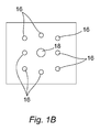
- the disposition of the LEDs 16 in relation to each other and the camera 18 is shown in Figure 1B .
- the LEDs 16 form a generally square pattern with the camera 18 substantially at the centre of the square pattern.
- the camera and the LEDs are located in the roof of the enclosure such that the LEDs illuminate the interior of the enclosure and the camera is capable of acquiring an image of the body part located within the enclosure.
- An output from the digital colour camera 18 is electrically connected to a Personal Computer (PC) 20, which comprises a Visual Display Unit (VDU) 22.
- the Personal Computer is in communication with an Epson R2880 printer 24, with communication being either wired or wireless depending on whether the printer is in the same locale as the Personal Computer or at a distant location.
- Software running on the PC is operative to control and operate the camera 18.
- the software has been developed for Microsoft Windows XP or higher using Visual Studio 2008 and Direct Show SDK.
- the Direct Show SDK provide for the interface with the camera with camera set-up controls provided by Mueller Optronic.
- the software is operative to provide a hardware accelerated live view of the body part inside the enclosure and controls for adjusting the camera parameters.
- the controls are only displayed when the apparatus is in a set-up mode to thereby reduce the likelihood of the operator adjusting the controls so as to compromise proper operation of the apparatus.
- the default control settings for the camera under particular lighting conditions are hard-coded into the software to reduce the likelihood of operator adjustments that might compromise proper operation of the apparatus. Design of such software is readily with the scope of the ordinary design skills of the person skilled in the art.
- the default control settings for the camera comprise the RGB (Red Green Blue) channel analogue gains, HSV (Hue Saturation and Value) representations of the RGB values, exposure time, the gain of the camera and gamma, contrast and saturation.
- the default control settings are determined by taking images of a Gretag MacBeth colour chart located in the enclosure and adjusting the control settings until the desired quality of image is obtained.
- the apparatus 10 further comprises paint mixing apparatus 26, which is operative to mix differently coloured pigments to provide a plurality of pigment mixtures 28.
- the differently coloured pigments are contained within a plurality of respective containers within the paint mixing apparatus.
- the containers are supported on a carousel arrangement so that each container is moved proximate a mixing container so that the container's contents may be dispensed into the mixing container.
- the contents of a container are dispensed by means of a syringe pump.
- the paint mixing apparatus 26 comprises a container for each of Red, Blue and Yellow, a container containing clear silicone and a container containing white silicone.
- the mixture typically comprises about 80% clear silicone, about 18% white silicone and about 2% for each of the Red, Blue and Yellow.
- the design of the paint mixing apparatus is readily within the ordinary design skills of the person of skill in the art.
- the paint mixing apparatus 26 is in communication with the Personal Computer 20, with communication being either wired or wireless depending on whether the paint mixing apparatus is in the same locale as the Personal Computer or at a distant location.
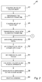
- a method according to the present invention will now be described with reference to Figure 2 , which represents steps of the method in flow-chart form 40.
- a Munsell Colour XRite Gretag MacBeth colour chart is placed in the enclosure 12 of Figure 1A and an image of the colour chart is acquired 42 by the digital colour camera 18.
- the colour chart image is conveyed to the Personal Computer (PC) 20.
- the PC is operative to determine a colour difference between each of the colour values in the colour chart image with each corresponding actual colour value for the colour chart stored in the PC.
- Each colour difference is translated into RGB positional space (3D colour space) such that the colour differences are in the form of sparse points in a Look Up Table (LUT) for each of Red, Green and Blue values.
- RGB positional space 3D colour space
- the PC is operative to interpolate between the sparse points in each LUT with a Catmull-ROM point fitting curve being used.
- the resulting LUT values are filtered by means of a rolling average filter with twelve taps.
- the thus determined LUTs are used to effect a calibration transformation of subsequently acquired images to thereby compensate for inaccuracies in the colour representation arising from acquisition by the digital colour camera.
- transformation of the colour chart image with the LUT based calibration transform produces a compensated colour chart image that more faithfully represents the true colours contained in the colour chart.
- the calibration transform may also include determining calibrations for one or more of the group comprising: light power, based on the perceived brightness of one or more greyscale values; saturation; gamma function; and contrast function.
- the camera 18 may also include an auto white balance to compensate for variation in camera sensitivity.
- the step of compensating for the variation in camera sensitivity may be performed before the brightness calibration is determined and corrected.
- the calibration transform may satisfy the requirements of an industry standard profile, such as those set by the International Colour Consortium (ICC). This is termed a colour model of the camera response.
- ICC International Colour Consortium
- Un-transformed and transformed RGB curves are shown in Figure 5 .
- the un-transformed curves for each of Red, Green and Blue are indicated by reference numeral 100 and the transformed curves are indicated by reference numeral 102.
- transformed curves are closer to the ideal straight, diagonal line than the un-transformed curves.
- the above described calibration procedure is normally only carried out at a conclusion to manufacture of apparatus according to the invention. However, the calibration procedure may be carried out in the field if the configuration of the apparatus is changed, e.g. if there is a change in lighting conditions or if there is a change in ambient temperature that is sufficient to warrant re-calibration.
- the wearer of a prosthetic right hand places his left hand in the enclosure 12 of Figure 1A .
- the digital colour camera is operative to acquire a series of images at a sampling rate of about one second.
- the series of images are displayed on the VDU 22 by way of the PC 20.
- a clinician inspects the displayed images to determine whether or not a full image of the hand is displayed and whether or not the hand is properly oriented within the enclosure. If not, the wearer moves his hand within the enclosure to remedy the lack of proper positioning.
- operator operates the PC, e.g. by means of a "capture" button on the software interface, such that the digital colour image displayed at that time is stored in the PC.
- the PC 20 is operative to transform the stored digital colour with the calibration transform to produce a compensated digital colour image 48. Further images of the hand, e.g. bottom and side images, may then be acquired and transformed as described above and depending on requirements. Thereafter the compensated digital colour image is displayed on the VDU 50 and the clinician, or painter, selects six to ten different areas on the image 52. The PC is then operative to determine the colour values of the selected areas in terms of Red, Blue, Yellow (RBY) values for the selected areas 54. Alternatively, RBY colour values may be determined on the basis of a predetermined recipe and without the clinician selecting the different areas.
- RBY colour values may be determined on the basis of a predetermined recipe and without the clinician selecting the different areas.
- the colour values are conveyed 56 to the paint mixing apparatus 26 and the paint mixing apparatus 26 is operative to produce paint mixtures of the correct colour 58 in dependence on the received colour values.
- the clinician, or painter paints the surface of the cosmetic covering with the paint mixtures 60.
- Data for acquired images and corresponding colour values are encrypted to reduce the likelihood of tampering and the proper operation of the apparatus being compromised.
- the colour of paint of a particular colour may vary from batch to batch.
- the colour value of a fresh batch of paint is determined with a spectrophotometer 72.
- a colour value determined by the spectrophotometer is conveyed to the PC 20, which stores a desired colour value for the particular colour in question, e.g. a colour value for a previously used batch of paint of the same colour.
- the PC is operative to compare the spectrophotometer determined colour value with the stored colour value 74 and to change a compensated digital colour image (see step 48 in Figure 2 ) to take account of a variation in the colour value.
- the paint mixing apparatus 26 is operative to mix paints in dependence on the compensated digital colour image variations in paint colour from batch to batch can be compensated for.
- the International Colour Consortium (ICC) colour profile for the Epson R2880 printer 24 is set for Premium Luster paper as the default Image Colour Management (ICM) profile upon conclusion of manufacture of apparatus according to the invention.
- ICM Image Colour Management
- the ICM settings provide for faithful printing of stored images.
- the printer 24 may be liable under certain circumstances to introduce errors in the reproduction of the colours of the acquired image. Therefore, calibration may be desired.
- a true Gretag MacBeth colour chart stored in the PC 20 is printed with the printer 24, 82.
- the digital colour camera 18 is used to acquire an image of the printed image and the acquired image is conveyed to the PC.
- the colour values in the acquired image of the colour chart are compared with the respective colour values in the stored colour chart.
- the PC is then operative to determine a printer calibration transform 84 in dependence on the colour value comparisons, with the printer calibration transform being effective to compensate for inaccuracies in the colour representation arising from printing with the printer.
- a compensated image of the wearer's hand is conveyed to the printer 82, the compensated image is transformed with the printer calibration transform 88 to take account of printer inaccuracies and the further compensated image is printed with the printer 88.
- the apparatus and method according to the present invention may be employed in other applications.
- the apparatus and method may be used in the cosmetics industry or in medical diagnosis. More specifically, the apparatus may be used to compare skin before and after the application of cosmetics to provide feedback to a user as to the appropriateness of the cosmetics applied.
- the apparatus may be used to detect skin colour profiles that are indicative of disease.
- An ultraviolet camera may be used instead of the colour camera 18 of Figure 1A to see below the surface of the skin. Such an ultraviolet camera may be particularly useful in detecting skin conditions that are not evident from an inspection of the skin surface.
Landscapes
- Health & Medical Sciences (AREA)
- Engineering & Computer Science (AREA)
- Vascular Medicine (AREA)
- Life Sciences & Earth Sciences (AREA)
- Oral & Maxillofacial Surgery (AREA)
- Transplantation (AREA)
- Biomedical Technology (AREA)
- Heart & Thoracic Surgery (AREA)
- Manufacturing & Machinery (AREA)
- Cardiology (AREA)
- Animal Behavior & Ethology (AREA)
- General Health & Medical Sciences (AREA)
- Public Health (AREA)
- Veterinary Medicine (AREA)
- Spectrometry And Color Measurement (AREA)
- Image Processing (AREA)
Description
- The present invention relates to a method and apparatus for colouring a cosmetic covering and in particular, but not exclusively, a method and apparatus for colouring a cosmetic covering for a prosthesis.
- Cosmetic coverings for prostheses are normally coloured to provide as life-like appearance as possible. One approach involves a clinician determining the appropriate colouring for a cosmetic covering by eye, e.g. by viewing the skin of the prosthesis wearer, and mixing differently coloured paints to achieve a match to the determined colours. The paint may be mixed from a palette consisting, for example, of eighty-four colours with each colour having two hundred and fifty six shades. The clinician then paints the cosmetic covering by hand. However, there is often no high degree of consistency in the colours from palette to palette. Also, clinicians will often see colours differently on account of a colour vision deficiency on the part of the clinician or on account of artificial lighting being used when the clinician is viewing the skin of the prosthesis wearer to determine the appropriate colouring. This approach typically results in 30% of painted cosmetic coverings being rejected.
- Another approach involves a clinician taking colour readings with a spectrophotometer at six to ten different locations on the prosthesis wearer's skin to determine appropriate colours for a cosmetic covering. The colour values, e.g. Red, Blue, Yellow (RBY) values, for each location are determined by a computer from the spectrophotometer readings and differently coloured paints are mixed in dependence on the determined colour values.
- One particular known method of colouring a cosmetic covering is disclosed in
US2006-0229755 . - The present inventor has appreciated shortcomings of the above known approaches.
- According to a first aspect of the present invention, there is provided a method of colouring a cosmetic covering in accordance with claim 1.
- The cosmetic covering may be configured to cover a prosthesis, such as a hand prosthesis, or foot prosthesis, for example. More specifically, the cosmetic covering may be a surface of the cosmetic covering. In one form, the at least one mixed paints may be applied by a person, e.g. using a brush. In another form, the at least one mixed paints may be applied by paint applying apparatus, such as spray painting apparatus.
- Alternatively or in addition, the method may comprise acquiring a plurality of different images of the part of the human or animal body. For example, where the part is a hand, an image of the top of the hand, an image of the bottom (i.e. palm side) of the hand and an image of the thumb side of the hand may be acquired. Hence, each of the plurality of acquired digital colour images may be transformed by the calibration transform.
- Alternatively or in addition, the method may further comprise disposing the part of the human or animal body in relation to the image acquisition apparatus and displaying an image of the part acquired by the image acquisition apparatus on display apparatus, such as on a Visual Display Unit (VDU). The present step may be carried out before the step of acquiring an image of the part to provide the digital colour image. Hence, the present step may be used to determine whether or not the part is properly disposed in relation to the image acquisition apparatus and, if not, the part may be moved or its orientation changed to achieve proper disposition.
- Alternatively or in addition, the method may comprise receiving the body part in an enclosed space.
- More specifically, the enclosed space may be illuminated in a controlled fashion by means of a light source. Alternatively or in addition, the enclosed space may be illuminated by a light source configured to provide for substantially uniform illumination in a plane, e.g. a plane extending generally perpendicular to a path between the image acquisition apparatus and the part of the human or animal body.
- Alternatively or in addition, the enclosed space may be illuminated by a light source configured to be disposed proximate the image acquisition apparatus. More specifically, the light source may be configured to receive a lens of the image acquisition apparatus such a light emitting part of the light source is disposed around the lens. Alternatively or in addition, the light source may comprise a light emitting part of annular form. The light emitting part may comprise a plurality of Light Emitting Diodes (LEDs) disposed in relation to each other in a generally square pattern.
- Alternatively or in addition, the data acquisition apparatus may comprise a digital camera. More specifically, the digital camera may be a true colour digital camera. The true colour nature of the digital camera may be afforded by a characteristic of an optical lens disposed between the part of the human or animal body and an aperture of the digital camera.
- Alternatively or in addition, the apparatus may be configured to control the camera in respect of at least one of: at least one RGB analogue gain; at least one of HSV values corresponding to RGB values; exposure time; a gain of the camera; gamma; white balance; light power; contrast; and saturation.
- Alternatively or in addition, the method may further comprise: displaying the compensated digital colour image on display apparatus; and selecting a plurality of different areas on the compensated digital colour image. The plurality of different areas may be selected by an operator, e.g. by means of pointing at each area with a mouse and clicking.
- More specifically, colour characteristics of the colours within the plurality of different selected areas may be conveyed to the paint mixing apparatus of the first aspect, which is operative to mix a plurality of paints of different colours in dependence on the colour characteristics to produce a plurality of mixed paints. The colour characteristics may be Red, Blue and Yellow (RBY) values determined from the plurality of different selected areas, e.g. by means of processing apparatus. The plurality of mixed paints may correspond respectively to colours within the plurality of different selected areas.
- Alternatively or in addition, the paint mixing apparatus may comprise a plurality of paint dispensers, each paint dispenser containing a paint of a different colour.
- Different batches of paint of a particular colour may be of a slightly different colour. Hence, it may be desired to provide for colour consistency from batch to batch. Therefore, alternatively or in addition, the method may further comprise determining a colour of a batch of paint, e.g. a fresh batch, by means of colour determining apparatus. The colour determining apparatus may comprise apparatus, such as a spectrophotometer, that is operative to determine a bulk colour value (e.g. at a measurement location) for the paint batch. The colour determining apparatus may be operative to determine the Red, Blue, Yellow (RBY) values of the paint.
- More specifically, the method may further comprise comparing the determined colour of the paint with a predetermined colour, e.g. as determined by measuring the colour of another batch of paint, such as the batch most recently present in the colour mixing apparatus.
- Alternatively or in addition, the method may further comprise changing proportions of paints of different colours used to produce a paint mixture in dependence on the determined colour of the batch of paint. Hence, for example, relative amounts of Red Blue and Yellow paints used to form the plurality of mixed paints may be changed to take account of a change in colour from one batch of paints to another.
- Alternatively or in addition, the method may further comprise: conveying the colour compensated digital colour image to printing apparatus; and printing the colour compensated digital colour image by means of the printing apparatus. The colour compensated digital colour image may be wirelessly conveyed to the printing apparatus.
- More specifically, the method may further comprise acquiring by image acquisition apparatus an image of an image printed by the printing apparatus to provide a digital colour printed image. The image acquisition apparatus may comprise a digital camera. Preferably, a calibration transform may have been determined for the image acquisition apparatus. Hence, any contrary effect as regards colour caused by the image acquisition apparatus and/or lighting when the image acquisition apparatus is operative may be minimised. The printed image may comprise a colour chart, e.g. a colour chart stored in processing apparatus. The digital colour printed image, e.g. of the colour chart, may be conveyed to processing apparatus.
- Alternatively or in addition, the method may comprise: determining a printer calibration transform for colours of an image, e.g. of a colour chart, printed by the printer; and transforming a colour compensated digital colour image in dependence on the printer calibration transform. Thus, the printer may print an image that properly reflects the true colours of the colour compensated digital colour image.
- According to a second aspect of the present invention, there is provided apparatus for colouring a cosmetic covering in accordance with
claim 14. - The cosmetic covering may be configured to cover a prosthesis, such as a hand prosthesis. More specifically, the cosmetic covering may be a surface of the cosmetic covering. In one form, the at least one mixed paints may be applied by a person, e.g. using a brush. In another form, the at least one mixed paints may be applied by paint applying apparatus, such as spray painting apparatus.
- More specifically, the processing apparatus of the second aspect may comprise a computer, such as a Personal Computer (PC). The image acquisition apparatus may comprise a colour digital camera and may be configured to convey the digital colour image to the processing apparatus for processing thereon.
- Further embodiments of the second aspect of the present invention may comprise one or more features of the first aspect of the present invention.
- The present invention will now be described by way of example only with reference to the following drawings, of which:
-
Figure 1A is a diagram of apparatus according to the present invention; -
Figure 1B shows the disposition of LEDs with respect to each other and the camera; -
Figure 2 is a flow chart representation of a method of colouring a cosmetic covering according to the present invention; -
Figure 3 is a flow chart representation of a method of compensating for variation in pigment colours; -
Figure 4 is a flow chart representation of a method of colour compensating a printer; and -
Figure 5 shows un-transformed and transformed RGB curves. - Apparatus for colouring a
cosmetic covering 10 is shown inFigure 1A . Theapparatus 10 comprises an enclosure, which defines an entirely enclosed space, with the exception of anaperture 14 of sufficient size and shape to allow a part of body, such as a hand, to be received within the enclosure. At least most of the interior surface of the enclosure is white. The apparatus also comprises an arrangement ofLEDs 16, each LED being an Osram Golden Dragon Plus, white, LW W5AM-JYKY-5K8L from Osram GmbH, Hellabrunner Strasse 1, 81543 München, Germany, and a 9.1 MPdigital colour camera 18, namely a microscope c mount camera MDCM-900 from Mueller Optronic of Am Hugel 10A, 99084 Erfurt, Germany. A 3 volt power supply provides electrical power for the LEDs. A 1 Ohm resistor is in series between each LED and the power supply. Thedigital colour camera 18 comprises a true colour low magnification video lens, namely a Navitar NMV-5WA standard C mount lens from Navitar Inc. of 200 Commerce Drive, Rochester NY 14623, USA. The disposition of theLEDs 16 in relation to each other and thecamera 18 is shown inFigure 1B . As can be seen fromFigure 1B , theLEDs 16 form a generally square pattern with thecamera 18 substantially at the centre of the square pattern. The camera and the LEDs are located in the roof of the enclosure such that the LEDs illuminate the interior of the enclosure and the camera is capable of acquiring an image of the body part located within the enclosure. An output from thedigital colour camera 18 is electrically connected to a Personal Computer (PC) 20, which comprises a Visual Display Unit (VDU) 22. The Personal Computer is in communication with anEpson R2880 printer 24, with communication being either wired or wireless depending on whether the printer is in the same locale as the Personal Computer or at a distant location. Software running on the PC is operative to control and operate thecamera 18. The software has been developed for Microsoft Windows XP or higher using Visual Studio 2008 and Direct Show SDK. The Direct Show SDK provide for the interface with the camera with camera set-up controls provided by Mueller Optronic. The software is operative to provide a hardware accelerated live view of the body part inside the enclosure and controls for adjusting the camera parameters. The controls are only displayed when the apparatus is in a set-up mode to thereby reduce the likelihood of the operator adjusting the controls so as to compromise proper operation of the apparatus. Likewise, the default control settings for the camera under particular lighting conditions are hard-coded into the software to reduce the likelihood of operator adjustments that might compromise proper operation of the apparatus. Design of such software is readily with the scope of the ordinary design skills of the person skilled in the art. The default control settings for the camera comprise the RGB (Red Green Blue) channel analogue gains, HSV (Hue Saturation and Value) representations of the RGB values, exposure time, the gain of the camera and gamma, contrast and saturation. The default control settings are determined by taking images of a Gretag MacBeth colour chart located in the enclosure and adjusting the control settings until the desired quality of image is obtained. Theapparatus 10 further comprisespaint mixing apparatus 26, which is operative to mix differently coloured pigments to provide a plurality ofpigment mixtures 28. The differently coloured pigments are contained within a plurality of respective containers within the paint mixing apparatus. The containers are supported on a carousel arrangement so that each container is moved proximate a mixing container so that the container's contents may be dispensed into the mixing container. The contents of a container are dispensed by means of a syringe pump. Hence, thepaint mixing apparatus 26 comprises a container for each of Red, Blue and Yellow, a container containing clear silicone and a container containing white silicone. When a particular colour is obtained, the mixture typically comprises about 80% clear silicone, about 18% white silicone and about 2% for each of the Red, Blue and Yellow. The design of the paint mixing apparatus is readily within the ordinary design skills of the person of skill in the art. Thepaint mixing apparatus 26 is in communication with thePersonal Computer 20, with communication being either wired or wireless depending on whether the paint mixing apparatus is in the same locale as the Personal Computer or at a distant location. - A method according to the present invention will now be described with reference to
Figure 2 , which represents steps of the method in flow-chart form 40. A Munsell Colour XRite Gretag MacBeth colour chart is placed in theenclosure 12 ofFigure 1A and an image of the colour chart is acquired 42 by thedigital colour camera 18. The colour chart image is conveyed to the Personal Computer (PC) 20. The PC is operative to determine a colour difference between each of the colour values in the colour chart image with each corresponding actual colour value for the colour chart stored in the PC. Each colour difference is translated into RGB positional space (3D colour space) such that the colour differences are in the form of sparse points in a Look Up Table (LUT) for each of Red, Green and Blue values. The PC is operative to interpolate between the sparse points in each LUT with a Catmull-ROM point fitting curve being used. The resulting LUT values are filtered by means of a rolling average filter with twelve taps. The thus determined LUTs are used to effect a calibration transformation of subsequently acquired images to thereby compensate for inaccuracies in the colour representation arising from acquisition by the digital colour camera. In other words, transformation of the colour chart image with the LUT based calibration transform produces a compensated colour chart image that more faithfully represents the true colours contained in the colour chart. - The calibration transform may also include determining calibrations for one or more of the group comprising: light power, based on the perceived brightness of one or more greyscale values; saturation; gamma function; and contrast function.
- The
camera 18 may also include an auto white balance to compensate for variation in camera sensitivity. The step of compensating for the variation in camera sensitivity may be performed before the brightness calibration is determined and corrected. - The calibration transform may satisfy the requirements of an industry standard profile, such as those set by the International Colour Consortium (ICC). This is termed a colour model of the camera response.
- Un-transformed and transformed RGB curves are shown in
Figure 5 . InFigure 5 , the un-transformed curves for each of Red, Green and Blue are indicated byreference numeral 100 and the transformed curves are indicated byreference numeral 102. As can be seen, transformed curves are closer to the ideal straight, diagonal line than the un-transformed curves. The above described calibration procedure is normally only carried out at a conclusion to manufacture of apparatus according to the invention. However, the calibration procedure may be carried out in the field if the configuration of the apparatus is changed, e.g. if there is a change in lighting conditions or if there is a change in ambient temperature that is sufficient to warrant re-calibration. - Referring again to
Figure 2 , the wearer of a prosthetic right hand places his left hand in theenclosure 12 ofFigure 1A . The digital colour camera is operative to acquire a series of images at a sampling rate of about one second. The series of images are displayed on theVDU 22 by way of thePC 20. A clinician inspects the displayed images to determine whether or not a full image of the hand is displayed and whether or not the hand is properly oriented within the enclosure. If not, the wearer moves his hand within the enclosure to remedy the lack of proper positioning. When the hand is positioned properly, operator operates the PC, e.g. by means of a "capture" button on the software interface, such that the digital colour image displayed at that time is stored in the PC. Then thePC 20 is operative to transform the stored digital colour with the calibration transform to produce a compensateddigital colour image 48. Further images of the hand, e.g. bottom and side images, may then be acquired and transformed as described above and depending on requirements. Thereafter the compensated digital colour image is displayed on theVDU 50 and the clinician, or painter, selects six to ten different areas on theimage 52. The PC is then operative to determine the colour values of the selected areas in terms of Red, Blue, Yellow (RBY) values for the selectedareas 54. Alternatively, RBY colour values may be determined on the basis of a predetermined recipe and without the clinician selecting the different areas. The colour values are conveyed 56 to thepaint mixing apparatus 26 and thepaint mixing apparatus 26 is operative to produce paint mixtures of thecorrect colour 58 in dependence on the received colour values. When the paint mixing is complete, the clinician, or painter, paints the surface of the cosmetic covering with thepaint mixtures 60. Data for acquired images and corresponding colour values are encrypted to reduce the likelihood of tampering and the proper operation of the apparatus being compromised. - The colour of paint of a particular colour may vary from batch to batch. Hence and referring to
Figure 3 , the colour value of a fresh batch of paint is determined with aspectrophotometer 72. A colour value determined by the spectrophotometer is conveyed to thePC 20, which stores a desired colour value for the particular colour in question, e.g. a colour value for a previously used batch of paint of the same colour. The PC is operative to compare the spectrophotometer determined colour value with the storedcolour value 74 and to change a compensated digital colour image (seestep 48 inFigure 2 ) to take account of a variation in the colour value. Hence, when thepaint mixing apparatus 26 is operative to mix paints in dependence on the compensated digital colour image variations in paint colour from batch to batch can be compensated for. - It is often desirable to provide a printed copy of an acquired image of wearer's hand, e.g. for the purposes of the clinician or for inspection by the wearer himself. The International Colour Consortium (ICC) colour profile for the
Epson R2880 printer 24 is set for Premium Luster paper as the default Image Colour Management (ICM) profile upon conclusion of manufacture of apparatus according to the invention. During use, the ICM settings provide for faithful printing of stored images. However, theprinter 24 may be liable under certain circumstances to introduce errors in the reproduction of the colours of the acquired image. Therefore, calibration may be desired. Hence and referring toFigure 4 a true Gretag MacBeth colour chart stored in thePC 20 is printed with theprinter digital colour camera 18 is used to acquire an image of the printed image and the acquired image is conveyed to the PC. The colour values in the acquired image of the colour chart are compared with the respective colour values in the stored colour chart. The PC is then operative to determine a printer calibration transform 84 in dependence on the colour value comparisons, with the printer calibration transform being effective to compensate for inaccuracies in the colour representation arising from printing with the printer. Hence and referring to step 48 inFigure 2 , a compensated image of the wearer's hand is conveyed to theprinter 82, the compensated image is transformed with the printer calibration transform 88 to take account of printer inaccuracies and the further compensated image is printed with theprinter 88. - Following calibration of the camera as is described above, an image of a Gretag MacBeth colour chart was acquired and printed. A spectrophotometer was used to determine colour values for each colour patch of the Gretag MacBeth colour chart and of the printed image of the Gretag MacBeth colour chart and the differences between corresponding values in the two sets of measurements were determined. The mean sum of the absolute differences was then determined to thereby provide a percentage error for the printed image as a whole. By following this procedure, the apparatus according to the invention was shown to have an error of substantially 5.76%. It should be noted that it is undesirable for the calibration transform to provide for ideal calibration, i.e. such that the values in each LUT describe a straight, diagonal line. This is because ideal calibration may involve RGB values becoming negative, i.e. the values may become de-saturated, with the consequence that image quality is reduced.
- The apparatus and method according to the present invention may be employed in other applications. For example, the apparatus and method may be used in the cosmetics industry or in medical diagnosis. More specifically, the apparatus may be used to compare skin before and after the application of cosmetics to provide feedback to a user as to the appropriateness of the cosmetics applied. Alternatively, the apparatus may be used to detect skin colour profiles that are indicative of disease. An ultraviolet camera may be used instead of the
colour camera 18 ofFigure 1A to see below the surface of the skin. Such an ultraviolet camera may be particularly useful in detecting skin conditions that are not evident from an inspection of the skin surface.
Claims (14)
- A method of colouring a cosmetic covering (10), the method comprising:acquiring an image of a part of a human or animal body with an image acquisition apparatus (18) to provide a digital colour image;characterised in that the method further comprises the steps of:acquiring an image of a colour chart with the image acquisition apparatus (18) to provide a colour chart image;determining a calibration transform for colours of the image acquired by the image acquisition apparatus (18) in dependence on the colour chart image and colour values represented in the colour chart, wherein the calibration transform includes transformations for each of Red, Green and Blue values and each Red, Green and Blue transformation includes a Look Up Table (LUT), wherein each LUT is determined by sparsely populating the LUT with colour differences between each of the colour values in the colour chart image and each corresponding actual colour for the colour chart and interpolating between the sparse points;transforming the digital colour image with the calibration transform to provide a colour compensated digital colour image (48);conveying at least one colour characteristic of at least one colour within the colour compensated digital colour image (48) to a paint mixing apparatus (26), which is operative to mix a plurality of paints of different colours in dependence on the at least one colour characteristic to produce at least one mixed paint (60); andapplying the at least one mixed paint (60) to a cosmetic covering (10).
- A method according to claim 1 comprising acquiring a plurality of different images of the part of the human or animal body.
- A method according to claim 1 or claim 2 further comprising the step of disposing the part of the human or animal body in relation to the image acquisition apparatus (18) and displaying an image of the part acquired by the image acquisition apparatus on display apparatus (22), the step being carried out before the step of acquiring an image of the part to provide the digital colour image.
- A method according to any preceding claim, in which the method further comprises: displaying the compensated digital colour image (48) on display apparatus (22); and selecting a plurality of different areas on the compensated digital colour image (48).
- A method according to claim 4, in which colour characteristics of the colours within the plurality of different selected areas are conveyed to the paint mixing apparatus (26) to produce a plurality of mixed paints (60).
- A method according to claim 5 further comprising applying the plurality of mixed paints (60) to the cosmetic covering (10).
- A method according to any preceding claim, in which the paint mixing apparatus (26) comprises a plurality of paint dispensers, each paint dispenser containing a paint of a different colour.
- A method according to claim 7 further comprising determining a colour of a batch of paint by means of colour determining apparatus, the colour determining apparatus comprising apparatus that is operative to determine a bulk colour value for the paint batch.
- A method according to claim 8 further comprising comparing the determined colour of the paint with a predetermined colour.
- A method according to claim 8 or 9 further comprising changing proportions of paints of different colours used to produce a paint mixture in dependence on the determined colour of the batch of paint.
- A method according to any preceding claim further comprising: conveying the colour compensated digital colour image (48) to printing apparatus (24); and printing the colour compensated digital colour image (48) by means of the printing apparatus (24).
- A method according to claim 11 further comprising acquiring by image acquisition apparatus (18) an image of an image printed by the printing apparatus (24) to provide a digital colour printed image.
- A method according to claim 12 further comprising: determining a printer calibration transform (84) for colours of an image printed by the printer (24); and transforming a colour compensated digital colour image (48) in dependence on the printer calibration transform (84).
- Apparatus for colouring a cosmetic covering (10), the apparatus comprising:image acquisition apparatus (18) operative to acquire an image of a part of a human or animal body to provide a digital colour image;characterised in that the image acquisition apparatus (18) is also operative to acquire an image of a colour chart to provide a colour chart image, and the apparatus further comprises:processing apparatus (20) operative to determine a calibration transform for colours of an image acquired by the image acquisition apparatus (18) in dependence on the colour chart image and colour values represented in the colour chart, wherein the calibration transform includes transformations for each of Red, Green and Blue values and each Red, Green and Blue transformation includes a Look Up Table (LUT), wherein each LUT is determined by sparsely populating the LUT with colour differences between each of the colour values in the colour chart image and each corresponding actual colour for the colour chart and interpolating between the sparse points,the processing apparatus (20) being further operative to transform the digital colour image with the calibration transform to provide a colour compensated digital colour image (48);paint mixing apparatus (26) operative to mix a plurality of paints of different colours in dependence on at least one colour characteristic of at least one colour within the colour compensated digital colour image (48) to produce at least one mixed paint (60); andpaint applying apparatus operative to apply the at least one mixed paint to a cosmetic covering (10).
Applications Claiming Priority (2)
| Application Number | Priority Date | Filing Date | Title |
|---|---|---|---|
| GB0922603A GB0922603D0 (en) | 2009-12-24 | 2009-12-24 | Skin colour determining apparatus and method |
| PCT/GB2010/052192 WO2011077156A1 (en) | 2009-12-24 | 2010-12-22 | Method and apparatus for colouring a cosmetic covering |
Publications (2)
| Publication Number | Publication Date |
|---|---|
| EP2515802A1 EP2515802A1 (en) | 2012-10-31 |
| EP2515802B1 true EP2515802B1 (en) | 2016-04-27 |
Family
ID=41716944
Family Applications (1)
| Application Number | Title | Priority Date | Filing Date |
|---|---|---|---|
| EP10807639.9A Active EP2515802B1 (en) | 2009-12-24 | 2010-12-22 | Method and apparatus for colouring a cosmetic covering |
Country Status (6)
| Country | Link |
|---|---|
| US (1) | US8995760B2 (en) |
| EP (1) | EP2515802B1 (en) |
| DK (1) | DK2515802T3 (en) |
| ES (1) | ES2581521T3 (en) |
| GB (1) | GB0922603D0 (en) |
| WO (1) | WO2011077156A1 (en) |
Families Citing this family (24)
| Publication number | Priority date | Publication date | Assignee | Title |
|---|---|---|---|---|
| GB0922603D0 (en) * | 2009-12-24 | 2010-02-10 | Touch Emas Ltd | Skin colour determining apparatus and method |
| GB201114264D0 (en) | 2011-08-18 | 2011-10-05 | Touch Emas Ltd | Improvements in or relating to prosthetics and orthotics |
| GB201302025D0 (en) | 2013-02-05 | 2013-03-20 | Touch Emas Ltd | Improvements in or relating to prosthetics |
| US9122918B2 (en) | 2013-03-15 | 2015-09-01 | Skin Republic, Inc. | Systems and methods for specifying and formulating customized topical agents |
| EP3102157B1 (en) | 2014-02-04 | 2019-04-17 | Rehabilitation Institute of Chicago | Modular and lightweight prosthesis components |
| GB201403265D0 (en) | 2014-02-25 | 2014-04-09 | Touch Emas Ltd | Prosthetic digit for use with touchscreen devices |
| GB201408253D0 (en) | 2014-05-09 | 2014-06-25 | Touch Emas Ltd | Systems and methods for controlling a prosthetic hand |
| GB201417541D0 (en) | 2014-10-03 | 2014-11-19 | Touch Bionics Ltd | Wrist device for a prosthetic limb |
| JP6574074B2 (en) | 2016-02-08 | 2019-09-11 | イクアリティ コスメティクス インコーポレイテッドEquality Cosmetics, Inc. | Apparatus and method for formulating and dispensing visually customized cosmetics |
| CN106131564A (en) * | 2016-07-28 | 2016-11-16 | 广东西奥物联网科技股份有限公司 | A kind of method and device that camera video stream is processed |
| EP3506857B1 (en) | 2016-09-02 | 2025-07-09 | Touch Bionics Limited | Systems and methods for prosthetic wrist rotation |
| US11185426B2 (en) | 2016-09-02 | 2021-11-30 | Touch Bionics Limited | Systems and methods for prosthetic wrist rotation |
| EP3548168A4 (en) | 2016-12-02 | 2021-01-20 | Shiseido Americas Corporation | SYSTEMS, METHODS AND APPARATUS FOR THE PRODUCTION OF PERSONALIZED TOPICAL DRUGS |
| WO2018165346A1 (en) | 2017-03-07 | 2018-09-13 | Matchco. | System and method for adjusting custom topical agents |
| EP3661476A4 (en) | 2017-07-25 | 2021-07-21 | Blee. LLC | SYSTEM AND DEVICE FOR CUSTOMIZING COSMETIC PRODUCTS |
| US10973660B2 (en) | 2017-12-15 | 2021-04-13 | Touch Bionics Limited | Powered prosthetic thumb |
| US10575623B2 (en) | 2018-06-29 | 2020-03-03 | Sephora USA, Inc. | Color capture system and device |
| WO2020014695A1 (en) | 2018-07-13 | 2020-01-16 | Shiseido Americas Corporation | System and method for adjusting custom topical agents |
| CN114174783B (en) | 2019-04-09 | 2024-10-18 | 资生堂株式会社 | Systems and methods for creating topical formulations with improved image capture |
| US11931270B2 (en) | 2019-11-15 | 2024-03-19 | Touch Bionics Limited | Prosthetic digit actuator |
| US20230022882A1 (en) | 2019-12-19 | 2023-01-26 | Touch Bionics Limited | Electromyography and motion based control of upper limb prosthetics |
| WO2022040392A1 (en) | 2020-08-19 | 2022-02-24 | Blee.LLC | System and device for customization of cosmetics |
| WO2023012008A1 (en) * | 2021-08-03 | 2023-02-09 | Otto Bock Healthcare Products Gmbh | Method for determining the wear of a prosthesis liner, and prosthesis liner therefor |
| AU2022345766A1 (en) * | 2021-09-15 | 2024-02-22 | Hollister Incorporated | Customized integrated ostomy pouch comfort panel and pouch cover and method of making same |
Family Cites Families (31)
| Publication number | Priority date | Publication date | Assignee | Title |
|---|---|---|---|---|
| GB2067074B (en) | 1979-12-21 | 1984-03-14 | Steeper Hugh Ltd | Silicon rubber covers for external prostheses |
| GB8616985D0 (en) | 1986-07-11 | 1986-08-20 | Steeper Hugh Ltd | Plasticized material |
| JPH07174631A (en) | 1993-12-16 | 1995-07-14 | Kao Corp | Skin colorimetric method and spectral reflectance spectrum estimation method |
| US5852675A (en) * | 1995-04-14 | 1998-12-22 | Kiyoshi Matsuo | Color chart for image correction and method of color correction |
| US6254385B1 (en) * | 1997-01-02 | 2001-07-03 | Lj Laboratories, Llc | Apparatus and method for measuring optical characteristics of teeth |
| US5785960A (en) | 1997-03-19 | 1998-07-28 | Elizabeth Arden Co., Division Of Conopco, Inc. | Method and system for customizing dermatological foundation products |
| US6111973A (en) * | 1997-05-29 | 2000-08-29 | Holt; Kenneth Dale | Method for producing color-comparable photographs with fleshtone color selections for prosthetic fabrication |
| US6177034B1 (en) | 1998-04-03 | 2001-01-23 | A-Pear Biometric Replications Inc. | Methods for making prosthetic surfaces |
| US6249348B1 (en) | 1998-11-23 | 2001-06-19 | Lj Laboratories, L.L.C. | Integrated spectrometer assembly and methods |
| US6437866B1 (en) | 1999-07-07 | 2002-08-20 | Fd Management, Inc. | System for assisting customers in selecting an optimum color cosmetic product |
| JP4421071B2 (en) | 2000-04-21 | 2010-02-24 | 株式会社資生堂 | Makeup counseling device |
| AU2001261160A1 (en) * | 2000-05-03 | 2001-11-12 | Stephen T Flock | Prosthesis and method of making |
| JP2002131135A (en) | 2000-10-20 | 2002-05-09 | Kao Corp | Reference color chart and makeup simulation device |
| JP2003134526A (en) | 2001-10-19 | 2003-05-09 | Univ Waseda | Color reproduction device and color reproduction method |
| US20040078299A1 (en) * | 2002-01-31 | 2004-04-22 | Kathleen Down-Logan | Portable color and style analysis, match and management system |
| JP2004073802A (en) | 2002-08-20 | 2004-03-11 | Forest Denki Kk | Multipurpose measuring unit for skin |
| US7394488B2 (en) * | 2003-10-30 | 2008-07-01 | Hewlett-Packard Development Company, L.P. | System and method for dual white balance compensation of images |
| WO2005071372A1 (en) * | 2004-01-23 | 2005-08-04 | Olympus Corporation | Image processing system and camera |
| US20060029909A1 (en) * | 2004-08-05 | 2006-02-09 | Kaczkowski Michael D | Method and apparatus for producing objective color references for color matching or identifying |
| EP1812968B1 (en) * | 2004-08-25 | 2019-01-16 | Callahan Cellular L.L.C. | Apparatus for multiple camera devices and method of operating same |
| WO2006058190A2 (en) | 2004-11-23 | 2006-06-01 | Color Savvy Systems Limited | Method for deriving consistent, repeatable color measurements from data provided by a digital imaging device |
| GB0504279D0 (en) * | 2005-03-02 | 2005-04-06 | Carroll Charles C | Skin colour matching system and method |
| WO2006106509A2 (en) | 2005-04-04 | 2006-10-12 | Hadasit Ltd. | Medical imaging method and system |
| WO2006110790A2 (en) * | 2005-04-12 | 2006-10-19 | Rehabilitation Institute Of Chicago | Method for creating covers for prosthetic devices and other dynamic supporting members |
| US7522768B2 (en) | 2005-09-09 | 2009-04-21 | Hewlett-Packard Development Company, L.P. | Capture and systematic use of expert color analysis |
| US7522769B2 (en) * | 2005-09-09 | 2009-04-21 | Hewlett-Packard Development Company, L.P. | Method and system for skin color estimation from an image |
| JP5005944B2 (en) | 2006-04-03 | 2012-08-22 | 株式会社Pfu | Color reproduction system |
| WO2009092868A1 (en) * | 2008-01-23 | 2009-07-30 | Ijina | Device and method for the space-colorimetric measurement of a three-dimensional object |
| GB0922603D0 (en) * | 2009-12-24 | 2010-02-10 | Touch Emas Ltd | Skin colour determining apparatus and method |
| US8571281B2 (en) * | 2010-07-13 | 2013-10-29 | Carestream Health, Inc. | Dental shade mapping |
| US8634640B2 (en) * | 2010-10-21 | 2014-01-21 | Hewlett-Packard Development Company, L.P. | Method and apparatus for selecting a color palette |
-
2009
- 2009-12-24 GB GB0922603A patent/GB0922603D0/en not_active Ceased
-
2010
- 2010-12-22 DK DK10807639.9T patent/DK2515802T3/en active
- 2010-12-22 US US13/502,753 patent/US8995760B2/en active Active
- 2010-12-22 EP EP10807639.9A patent/EP2515802B1/en active Active
- 2010-12-22 ES ES10807639.9T patent/ES2581521T3/en active Active
- 2010-12-22 WO PCT/GB2010/052192 patent/WO2011077156A1/en not_active Ceased
Non-Patent Citations (1)
| Title |
|---|
| None * |
Also Published As
| Publication number | Publication date |
|---|---|
| DK2515802T3 (en) | 2016-08-15 |
| WO2011077156A1 (en) | 2011-06-30 |
| US8995760B2 (en) | 2015-03-31 |
| EP2515802A1 (en) | 2012-10-31 |
| GB0922603D0 (en) | 2010-02-10 |
| US20120229828A1 (en) | 2012-09-13 |
| ES2581521T3 (en) | 2016-09-06 |
Similar Documents
| Publication | Publication Date | Title |
|---|---|---|
| US8995760B2 (en) | Method and apparatus for colouring a cosmetic covering | |
| US10962416B2 (en) | Color conversion system, color conversion apparatus and color conversion method | |
| JP5967441B2 (en) | Color processing method, color processing apparatus, and color processing system | |
| US11748912B2 (en) | Hyperspectral imaging spectrophotometer and system | |
| US7064830B2 (en) | Dental color imaging system | |
| CN101175979B (en) | Numerical method for matching colorants | |
| CN109141640A (en) | Acetes chinensis method, system, equipment and storage medium based on machine vision | |
| CN102331301B (en) | Teeth Shadow Mapping | |
| US20050018191A1 (en) | Apparatus and method for measuring colour | |
| EP1771013A3 (en) | Image colour correction based on skin colour | |
| US7187797B2 (en) | Color machine vision system for colorimetry | |
| US7262779B1 (en) | Differential imaging colorimeter | |
| JP2002529727A (en) | Method and apparatus for measuring the chromaticity of colored surfaces | |
| EP1963802A1 (en) | Dental colorimetry apparatus | |
| CN101001520B (en) | Measuring method and measuring device using color image | |
| Daul et al. | Building a color classification system for textured and hue homogeneous surfaces: system calibration and algorithm | |
| CN118314076A (en) | Method and system for determining pattern deviation values of a visible surface of a panel | |
| JP2019153931A (en) | Measuring device, method for setting parameter for color measurement conversion in measuring device, and industrial product inspected by measuring device | |
| JP2001283210A (en) | Color management system | |
| US20250265959A1 (en) | Color measuring and color adjusting device | |
| CN105101515A (en) | Lamp driving method and device | |
| Marguier et al. | A home décor expert in your camera | |
| Hill | Softproofing system for accurate colour matching and study of observer metamerism | |
| Mandic et al. | Corresponding colors: visual and predictive data | |
| Herbert et al. | Absolute and relative colorimetric evaluation for precise color on screen |
Legal Events
| Date | Code | Title | Description |
|---|---|---|---|
| PUAI | Public reference made under article 153(3) epc to a published international application that has entered the european phase |
Free format text: ORIGINAL CODE: 0009012 |
|
| 17P | Request for examination filed |
Effective date: 20120416 |
|
| AK | Designated contracting states |
Kind code of ref document: A1 Designated state(s): AL AT BE BG CH CY CZ DE DK EE ES FI FR GB GR HR HU IE IS IT LI LT LU LV MC MK MT NL NO PL PT RO RS SE SI SK SM TR |
|
| DAX | Request for extension of the european patent (deleted) | ||
| RAP1 | Party data changed (applicant data changed or rights of an application transferred) |
Owner name: TOUCH BIONICS LIMITED |
|
| 17Q | First examination report despatched |
Effective date: 20150319 |
|
| GRAP | Despatch of communication of intention to grant a patent |
Free format text: ORIGINAL CODE: EPIDOSNIGR1 |
|
| INTG | Intention to grant announced |
Effective date: 20151118 |
|
| RIN1 | Information on inventor provided before grant (corrected) |
Inventor name: GILL, HUGH |
|
| GRAR | Information related to intention to grant a patent recorded |
Free format text: ORIGINAL CODE: EPIDOSNIGR71 |
|
| GRAS | Grant fee paid |
Free format text: ORIGINAL CODE: EPIDOSNIGR3 |
|
| GRAA | (expected) grant |
Free format text: ORIGINAL CODE: 0009210 |
|
| INTG | Intention to grant announced |
Effective date: 20160314 |
|
| AK | Designated contracting states |
Kind code of ref document: B1 Designated state(s): AL AT BE BG CH CY CZ DE DK EE ES FI FR GB GR HR HU IE IS IT LI LT LU LV MC MK MT NL NO PL PT RO RS SE SI SK SM TR |
|
| REG | Reference to a national code |
Ref country code: GB Ref legal event code: FG4D |
|
| REG | Reference to a national code |
Ref country code: CH Ref legal event code: EP |
|
| REG | Reference to a national code |
Ref country code: AT Ref legal event code: REF Ref document number: 793914 Country of ref document: AT Kind code of ref document: T Effective date: 20160515 |
|
| REG | Reference to a national code |
Ref country code: IE Ref legal event code: FG4D |
|
| REG | Reference to a national code |
Ref country code: DE Ref legal event code: R096 Ref document number: 602010032904 Country of ref document: DE |
|
| REG | Reference to a national code |
Ref country code: NL Ref legal event code: FP |
|
| REG | Reference to a national code |
Ref country code: DK Ref legal event code: T3 Effective date: 20160808 |
|
| REG | Reference to a national code |
Ref country code: SE Ref legal event code: TRGR |
|
| REG | Reference to a national code |
Ref country code: LT Ref legal event code: MG4D |
|
| REG | Reference to a national code |
Ref country code: ES Ref legal event code: FG2A Ref document number: 2581521 Country of ref document: ES Kind code of ref document: T3 Effective date: 20160906 |
|
| REG | Reference to a national code |
Ref country code: AT Ref legal event code: MK05 Ref document number: 793914 Country of ref document: AT Kind code of ref document: T Effective date: 20160427 |
|
| PG25 | Lapsed in a contracting state [announced via postgrant information from national office to epo] |
Ref country code: PL Free format text: LAPSE BECAUSE OF FAILURE TO SUBMIT A TRANSLATION OF THE DESCRIPTION OR TO PAY THE FEE WITHIN THE PRESCRIBED TIME-LIMIT Effective date: 20160427 Ref country code: LT Free format text: LAPSE BECAUSE OF FAILURE TO SUBMIT A TRANSLATION OF THE DESCRIPTION OR TO PAY THE FEE WITHIN THE PRESCRIBED TIME-LIMIT Effective date: 20160427 Ref country code: NO Free format text: LAPSE BECAUSE OF FAILURE TO SUBMIT A TRANSLATION OF THE DESCRIPTION OR TO PAY THE FEE WITHIN THE PRESCRIBED TIME-LIMIT Effective date: 20160727 |
|
| REG | Reference to a national code |
Ref country code: FR Ref legal event code: PLFP Year of fee payment: 7 |
|
| PG25 | Lapsed in a contracting state [announced via postgrant information from national office to epo] |
Ref country code: AT Free format text: LAPSE BECAUSE OF FAILURE TO SUBMIT A TRANSLATION OF THE DESCRIPTION OR TO PAY THE FEE WITHIN THE PRESCRIBED TIME-LIMIT Effective date: 20160427 Ref country code: LV Free format text: LAPSE BECAUSE OF FAILURE TO SUBMIT A TRANSLATION OF THE DESCRIPTION OR TO PAY THE FEE WITHIN THE PRESCRIBED TIME-LIMIT Effective date: 20160427 Ref country code: PT Free format text: LAPSE BECAUSE OF FAILURE TO SUBMIT A TRANSLATION OF THE DESCRIPTION OR TO PAY THE FEE WITHIN THE PRESCRIBED TIME-LIMIT Effective date: 20160829 Ref country code: HR Free format text: LAPSE BECAUSE OF FAILURE TO SUBMIT A TRANSLATION OF THE DESCRIPTION OR TO PAY THE FEE WITHIN THE PRESCRIBED TIME-LIMIT Effective date: 20160427 Ref country code: RS Free format text: LAPSE BECAUSE OF FAILURE TO SUBMIT A TRANSLATION OF THE DESCRIPTION OR TO PAY THE FEE WITHIN THE PRESCRIBED TIME-LIMIT Effective date: 20160427 |
|
| PG25 | Lapsed in a contracting state [announced via postgrant information from national office to epo] |
Ref country code: BE Free format text: LAPSE BECAUSE OF FAILURE TO SUBMIT A TRANSLATION OF THE DESCRIPTION OR TO PAY THE FEE WITHIN THE PRESCRIBED TIME-LIMIT Effective date: 20160427 |
|
| REG | Reference to a national code |
Ref country code: DE Ref legal event code: R097 Ref document number: 602010032904 Country of ref document: DE |
|
| PG25 | Lapsed in a contracting state [announced via postgrant information from national office to epo] |
Ref country code: RO Free format text: LAPSE BECAUSE OF FAILURE TO SUBMIT A TRANSLATION OF THE DESCRIPTION OR TO PAY THE FEE WITHIN THE PRESCRIBED TIME-LIMIT Effective date: 20160427 Ref country code: SK Free format text: LAPSE BECAUSE OF FAILURE TO SUBMIT A TRANSLATION OF THE DESCRIPTION OR TO PAY THE FEE WITHIN THE PRESCRIBED TIME-LIMIT Effective date: 20160427 Ref country code: EE Free format text: LAPSE BECAUSE OF FAILURE TO SUBMIT A TRANSLATION OF THE DESCRIPTION OR TO PAY THE FEE WITHIN THE PRESCRIBED TIME-LIMIT Effective date: 20160427 Ref country code: CZ Free format text: LAPSE BECAUSE OF FAILURE TO SUBMIT A TRANSLATION OF THE DESCRIPTION OR TO PAY THE FEE WITHIN THE PRESCRIBED TIME-LIMIT Effective date: 20160427 |
|
| REG | Reference to a national code |
Ref country code: GR Ref legal event code: EP Ref document number: 20160401760 Country of ref document: GR Effective date: 20161020 |
|
| PG25 | Lapsed in a contracting state [announced via postgrant information from national office to epo] |
Ref country code: SM Free format text: LAPSE BECAUSE OF FAILURE TO SUBMIT A TRANSLATION OF THE DESCRIPTION OR TO PAY THE FEE WITHIN THE PRESCRIBED TIME-LIMIT Effective date: 20160427 |
|
| PLBE | No opposition filed within time limit |
Free format text: ORIGINAL CODE: 0009261 |
|
| STAA | Information on the status of an ep patent application or granted ep patent |
Free format text: STATUS: NO OPPOSITION FILED WITHIN TIME LIMIT |
|
| 26N | No opposition filed |
Effective date: 20170130 |
|
| PG25 | Lapsed in a contracting state [announced via postgrant information from national office to epo] |
Ref country code: SI Free format text: LAPSE BECAUSE OF FAILURE TO SUBMIT A TRANSLATION OF THE DESCRIPTION OR TO PAY THE FEE WITHIN THE PRESCRIBED TIME-LIMIT Effective date: 20160427 |
|
| PG25 | Lapsed in a contracting state [announced via postgrant information from national office to epo] |
Ref country code: FI Free format text: LAPSE BECAUSE OF NON-PAYMENT OF DUE FEES Effective date: 20161222 |
|
| REG | Reference to a national code |
Ref country code: DK Ref legal event code: EBP Effective date: 20161231 Ref country code: CH Ref legal event code: PL |
|
| REG | Reference to a national code |
Ref country code: SE Ref legal event code: EUG |
|
| REG | Reference to a national code |
Ref country code: NL Ref legal event code: MM Effective date: 20170101 |
|
| PG25 | Lapsed in a contracting state [announced via postgrant information from national office to epo] |
Ref country code: SE Free format text: LAPSE BECAUSE OF NON-PAYMENT OF DUE FEES Effective date: 20161223 |
|
| PG25 | Lapsed in a contracting state [announced via postgrant information from national office to epo] |
Ref country code: MC Free format text: LAPSE BECAUSE OF FAILURE TO SUBMIT A TRANSLATION OF THE DESCRIPTION OR TO PAY THE FEE WITHIN THE PRESCRIBED TIME-LIMIT Effective date: 20160427 Ref country code: NL Free format text: LAPSE BECAUSE OF NON-PAYMENT OF DUE FEES Effective date: 20170101 |
|
| REG | Reference to a national code |
Ref country code: IE Ref legal event code: MM4A |
|
| PG25 | Lapsed in a contracting state [announced via postgrant information from national office to epo] |
Ref country code: LU Free format text: LAPSE BECAUSE OF NON-PAYMENT OF DUE FEES Effective date: 20161222 Ref country code: GR Free format text: LAPSE BECAUSE OF NON-PAYMENT OF DUE FEES Effective date: 20170707 Ref country code: LI Free format text: LAPSE BECAUSE OF NON-PAYMENT OF DUE FEES Effective date: 20161231 Ref country code: CH Free format text: LAPSE BECAUSE OF NON-PAYMENT OF DUE FEES Effective date: 20161231 Ref country code: IT Free format text: LAPSE BECAUSE OF NON-PAYMENT OF DUE FEES Effective date: 20161222 |
|
| REG | Reference to a national code |
Ref country code: FR Ref legal event code: PLFP Year of fee payment: 8 |
|
| PG25 | Lapsed in a contracting state [announced via postgrant information from national office to epo] |
Ref country code: IE Free format text: LAPSE BECAUSE OF NON-PAYMENT OF DUE FEES Effective date: 20161222 |
|
| PG25 | Lapsed in a contracting state [announced via postgrant information from national office to epo] |
Ref country code: DK Free format text: LAPSE BECAUSE OF NON-PAYMENT OF DUE FEES Effective date: 20161231 |
|
| PG25 | Lapsed in a contracting state [announced via postgrant information from national office to epo] |
Ref country code: ES Free format text: LAPSE BECAUSE OF NON-PAYMENT OF DUE FEES Effective date: 20171223 Ref country code: HU Free format text: LAPSE BECAUSE OF FAILURE TO SUBMIT A TRANSLATION OF THE DESCRIPTION OR TO PAY THE FEE WITHIN THE PRESCRIBED TIME-LIMIT; INVALID AB INITIO Effective date: 20101222 Ref country code: CY Free format text: LAPSE BECAUSE OF FAILURE TO SUBMIT A TRANSLATION OF THE DESCRIPTION OR TO PAY THE FEE WITHIN THE PRESCRIBED TIME-LIMIT Effective date: 20160427 |
|
| PG25 | Lapsed in a contracting state [announced via postgrant information from national office to epo] |
Ref country code: IS Free format text: LAPSE BECAUSE OF FAILURE TO SUBMIT A TRANSLATION OF THE DESCRIPTION OR TO PAY THE FEE WITHIN THE PRESCRIBED TIME-LIMIT Effective date: 20160427 Ref country code: MK Free format text: LAPSE BECAUSE OF FAILURE TO SUBMIT A TRANSLATION OF THE DESCRIPTION OR TO PAY THE FEE WITHIN THE PRESCRIBED TIME-LIMIT Effective date: 20160427 |
|
| PG25 | Lapsed in a contracting state [announced via postgrant information from national office to epo] |
Ref country code: BG Free format text: LAPSE BECAUSE OF FAILURE TO SUBMIT A TRANSLATION OF THE DESCRIPTION OR TO PAY THE FEE WITHIN THE PRESCRIBED TIME-LIMIT Effective date: 20160427 |
|
| PG25 | Lapsed in a contracting state [announced via postgrant information from national office to epo] |
Ref country code: MT Free format text: LAPSE BECAUSE OF NON-PAYMENT OF DUE FEES Effective date: 20161222 |
|
| PG25 | Lapsed in a contracting state [announced via postgrant information from national office to epo] |
Ref country code: AL Free format text: LAPSE BECAUSE OF FAILURE TO SUBMIT A TRANSLATION OF THE DESCRIPTION OR TO PAY THE FEE WITHIN THE PRESCRIBED TIME-LIMIT Effective date: 20160427 |
|
| REG | Reference to a national code |
Ref country code: ES Ref legal event code: FD2A Effective date: 20181106 |
|
| PG25 | Lapsed in a contracting state [announced via postgrant information from national office to epo] |
Ref country code: ES Free format text: LAPSE BECAUSE OF NON-PAYMENT OF DUE FEES Effective date: 20161223 |
|
| P01 | Opt-out of the competence of the unified patent court (upc) registered |
Effective date: 20230518 |
|
| PGFP | Annual fee paid to national office [announced via postgrant information from national office to epo] |
Ref country code: GB Payment date: 20251219 Year of fee payment: 16 |
|
| PGFP | Annual fee paid to national office [announced via postgrant information from national office to epo] |
Ref country code: FR Payment date: 20251211 Year of fee payment: 16 |
|
| PGFP | Annual fee paid to national office [announced via postgrant information from national office to epo] |
Ref country code: TR Payment date: 20251128 Year of fee payment: 16 |
|
| PGFP | Annual fee paid to national office [announced via postgrant information from national office to epo] |
Ref country code: DE Payment date: 20251222 Year of fee payment: 16 |