EP2515590A1 - Wireless base station, and relay device - Google Patents
Wireless base station, and relay device Download PDFInfo
- Publication number
- EP2515590A1 EP2515590A1 EP10837688A EP10837688A EP2515590A1 EP 2515590 A1 EP2515590 A1 EP 2515590A1 EP 10837688 A EP10837688 A EP 10837688A EP 10837688 A EP10837688 A EP 10837688A EP 2515590 A1 EP2515590 A1 EP 2515590A1
- Authority
- EP
- European Patent Office
- Prior art keywords
- synchronous signal
- radio equipment
- time
- relay device
- frame
- Prior art date
- Legal status (The legal status is an assumption and is not a legal conclusion. Google has not performed a legal analysis and makes no representation as to the accuracy of the status listed.)
- Withdrawn
Links
Images



Classifications
-
- H—ELECTRICITY
- H04—ELECTRIC COMMUNICATION TECHNIQUE
- H04B—TRANSMISSION
- H04B7/00—Radio transmission systems, i.e. using radiation field
- H04B7/24—Radio transmission systems, i.e. using radiation field for communication between two or more posts
- H04B7/26—Radio transmission systems, i.e. using radiation field for communication between two or more posts at least one of which is mobile
- H04B7/2603—Arrangements for wireless physical layer control
- H04B7/2606—Arrangements for base station coverage control, e.g. by using relays in tunnels
-
- H—ELECTRICITY
- H04—ELECTRIC COMMUNICATION TECHNIQUE
- H04W—WIRELESS COMMUNICATION NETWORKS
- H04W56/00—Synchronisation arrangements
- H04W56/0055—Synchronisation arrangements determining timing error of reception due to propagation delay
- H04W56/0065—Synchronisation arrangements determining timing error of reception due to propagation delay using measurement of signal travel time
- H04W56/009—Closed loop measurements
-
- H—ELECTRICITY
- H04—ELECTRIC COMMUNICATION TECHNIQUE
- H04W—WIRELESS COMMUNICATION NETWORKS
- H04W88/00—Devices specially adapted for wireless communication networks, e.g. terminals, base stations or access point devices
- H04W88/08—Access point devices
- H04W88/085—Access point devices with remote components
Definitions
- the present invention relates to a radio base station and a relay device.
- CPRI Common Public Radio Interface
- BTS Base Transceiver Station
- REC Radio Equipment Control
- the radio equipment controller REC and the radio equipment device RE insert a synchronous signal "SYNC" at a head position of each hyper frame and transmit the hyper frame.
- the radio equipment controller REC is configured to insert a first synchronous signal into "SYNC” in each hyper frame and transmit the first synchronous signal to the radio equipment device RE, and to acquire a second synchronous signal inserted into "SYNC" in each hyper frame, from the radio equipment device RE.
- the radio equipment controller REC is capable of calculating round-trip time RTT of the radio equipment device RE at the radio equipment controller REC, based on a difference T14 between transmission time R1 of the first synchronous signal and reception time R4 of the second synchronous signal.
- CPRI has studied implementation of a radio base station BTS which incorporates both a radio equipment controller REC for W-CDMA system and a radio equipment controller REC for LTE (Long Term Evolution) system.
- the above synchronous signals are configured to terminate at a first link between the radio equipment controller REC and a relay device and at a second link between the relay device and the radio equipment device RE.
- an object of the present invention is to provide a radio base station and a relay device which can accurately calculate round-trip time of a radio equipment device RE at each radio equipment controller REC, even when a relay device is provided.
- a radio base station including a radio equipment controller, a relay device, and a radio equipment device which are connected via a physical line, wherein a synchronous signal, which is inserted into a predetermined position in a frame and transmitted, is configured to terminate at a first link between the radio equipment controller and the relay device and to terminate at a second link between the relay device and the radio equipment device
- the relay device includes: a first synchronous signal reception unit configured to extract a first synchronous signal from a predetermined position in a frame received from the radio equipment controller via the first link; a second synchronous signal transmission unit configured to insert a second synchronous signal into the predetermined position of the frame and to transmit the second synchronous signal to the radio equipment device via the second link, in accordance with the extracted first synchronous signal; a third synchronous signal reception unit configured to extract a third synchronous signal from the predetermined position in the frame received from the radio equipment device via the second link; a fourth synchronous signal transmission unit configured to insert a fourth synchronous signal
- the timing adjustment unit may be configured to calculate a total time of processing delay time in the relay device and round-trip time of the radio equipment device at the relay device, from a difference between reception time of the first synchronous signal and transmission time of the second synchronous signal, a difference between the transmission time of the second synchronous signal and reception time of the third synchronous signal, and a difference between the reception time of the third synchronous signal and transmission time of the fourth synchronous signal, and to delay the transmission timing of the frame to be transmitted by the second synchronous signal transmission unit, by the total time.
- a relay device connected to a radio equipment controller and a radio equipment device via a physical line and provided in a radio base station, wherein a synchronous signal, which is inserted into a predetermined position in a frame and transmitted, is configured to terminate at a first link between the radio equipment controller and the relay device and to terminate at a second link between the relay device and the radio equipment device, and the relay device includes: a first synchronous signal reception unit configured to extract a first synchronous signal from a predetermined position in a frame received from the radio equipment controller via the first link; a second synchronous signal transmission unit configured to insert a second synchronous signal into the predetermined position in the frame and to transmit the second synchronous signal to the radio equipment device via the second link, in accordance with the extracted first synchronous signal; a third synchronous signal reception unit configured to extract a third synchronous signal from the predetermined position in the frame received from the radio equipment device via the second link; a fourth synchronous signal transmission unit configured to insert a fourth synchronous signal
- the timing adjustment unit may be configured to calculate a total time of processing delay time in the relay device and the round-time delay time in the relay device, from a difference between reception time of the first synchronous signal and transmission time of the second synchronous signal, a difference between the transmission time of the second synchronous signal and reception time of the third synchronous signal, and a difference between the reception time of the third synchronous signal and transmission time of the fourth synchronous signal, and to delay the transmission timing of the frame to be transmitted by the second synchronous signal transmission unit, by the total time.
- a radio base station according to the first embodiment of the invention will be described with reference to Fig. 1 through Fig. 4 .
- a radio base station BTS As shown in Fig. 1 , a radio base station BTS according to the embodiment is provided with a radio equipment device RE, a relay device 10, and multiple radio equipment controllers REC#1, REC#2.
- the radio equipment device RE, the relay device 10, and the radio equipment controllers REC#1, REC#2 are separate devices, and connected to each other via a physical line such as an optical line, an electric line, or the like.
- the radio equipment device RE, the relay device 10, and the radio equipment controllers REC#1, REC#2 are those specified by CPRI.
- the radio equipment controller REC#1 is a radio equipment controller REC for W-CDMA system
- the radio equipment controller REC#2 is a radio equipment controller REC for LTE system.
- the radio equipment controllers REC#1 and REC#2 will be collectively referred to as the radio equipment controller REC.
- a configuration is such that as layer 2 information, "user plane information,” “control and management plane information,” and “SYNC information (synchronous signal)" are transmitted and received in a first link between the radio equipment controller REC and the relay device 10, and a second link between the relay device 10 and the radio equipment device RE.
- layer 2 information "user plane information,” “control and management plane information,” and “SYNC information (synchronous signal)" are transmitted and received in a first link between the radio equipment controller REC and the relay device 10, and a second link between the relay device 10 and the radio equipment device RE.
- the user plane information is inserted in a user plane information area
- the control and management plane information is inserted in a control and management plane information area
- the SYNC information (synchronous signal information) is inserted into a SYNC information area.
- the configuration is such that as layer 2 information, "IQ data,” “vendor specific data,” “Ethernet ( Registered trademark) data,” “HDLC data,” “L1 inband protocol data,” and the like are transmitted and received in the first link between the radio equipment controller REC and the relay device 10, and the second link between the relay device 10 and the radio equipment device RE.
- the IQ data is inserted into an IQ data area
- the vendor specific data is inserted into a vendor specific data area
- the Ethernet (Registered trademark) data is inserted into an Ethernet (Registered trademark) data area
- the HDLC data is inserted into an HDLC data area
- the L1 inband protocol data is inserted into an L1 inband protocol data area.
- each of the layer 3 information and the layer 2 information is configured to terminate in the first link and the second link.
- the relay device 10 is provided with a first synchronous signal reception unit 11, a second synchronous signal transmission unit 12, a third synchronous signal reception unit 13, a fourth synchronous signal transmission unit 14, and a timing adjustment unit 15.
- the first synchronous signal reception unit 11 is configured to extract a first synchronous signal from a predetermined position (SYNC information area) in a frame received from the radio equipment controller REC via the first link.
- the second synchronous signal transmission unit 12 is configured to insert a second synchronous signal into the predetermined position (SYNC information area) in the frame and to transmit the second synchronous signal to the radio equipment device RE via the second link, in accordance with the first synchronous signal extracted by the first synchronous signal reception unit 11.
- the third synchronous signal reception unit 13 is configured to extract a third synchronous signal corresponding to the second synchronous signal mentioned above, from the predetermined position (SYNC information area) in the frame received from the radio equipment device RE via the second link.
- the fourth synchronous signal transmission unit 14 is configured to insert a fourth synchronous signal into the predetermined position (SYNC information area) in the frame and to transmit the fourth synchronous signal to the radio equipment controller REC via the first link, in accordance with the third synchronous signal extracted by the third synchronous signal reception unit 13.
- the timing adjustment unit 15 is configured to adjust transmission timing of the frame to be transmitted by the second synchronous signal transmission unit 14, based on processing delay time in the relay device 10 and round-trip time RTT of the radio equipment device RE at the relay device 10.
- the predetermined position (SYNC information area) is assumed to be provided in an area A specified by BFN (NodeB Frame Number) #0 and HFN (Hyper Frame Number) #0 in the frame.
- the radio equipment controller REC inserts a first synchronous signal into the predetermined position (SYNC information area) in the frame and transmits the first synchronous signal to the relay device 10.
- the first synchronous signal transmission unit 12 of the relay device 10 acquires the first synchronous signal from the predetermined position (SYNC information area) in the frame.
- the second synchronous signal transmission unit 12 of the relay device 10 inserts a second synchronous signal into the predetermined position (SYNC information area) in the frame and transmits the second synchronous signal to the radio equipment device RE.
- a difference between the reception time RB2 of the first synchronous signal at the relay device 10 and transmission time RB1 of the second synchronous signal at the relay device 10 is "delay time in the relay device 10".
- the radio equipment device RE acquires the second synchronous signal from the predetermined position (SYNC information area) in the frame.
- a difference between the transmission time RB1 of the second synchronous signal at the relay device 10 and the reception time R2 of the second synchronous signal at the radio equipment device RE is "T12 (2)".
- the radio equipment device RE inserts a third synchronous signal into the predetermined position (SYNC information area) in the frame and transmits the third synchronous signal to the relay device 10.
- a difference between the reception time R2 of the second synchronous signal at the radio equipment device RE and the transmission time R3 of the third synchronous signal at the radio equipment device RE is "delay time (T offset ) in the radio equipment device RE".
- the third synchronous signal reception unit 13 of the relay device 10 acquires the third synchronous signal from the predetermined position (SYNC information area) in the frame.
- a difference between the transmission time R3 of the third synchronous signal at the radio equipment device RE and reception time RB4 of a third synchronized response signal at the relay device 10 is "T12(2)".
- the fourth synchronous signal transmission unit 14 of the relay device 10 inserts a fourth synchronous signal into the predetermined position (SYNC information area) in the frame and transmits the fourth synchronous signal to the radio equipment controller REC.
- a difference between the reception time RB4 of the third synchronous signal at the relay device 10 and the transmission time RB3 of the fourth synchronous signal at the relay device 10 is "delay time in the relay device 10".
- the radio equipment controller REC acquires the fourth synchronous signal from the predetermined position (SYNC information area) in the frame.
- a difference between the reception time RB3 of the fourth synchronous signal at the relay device 10 and the transmission time R4 of the fourth synchronous signal at the radio equipment controller REC is "T12(1)".
- a difference "T14" between the transmission time R1 of the first synchronous signal at the radio equipment controller REC and the reception time R4 of the fourth synchronous signal at the radio equipment controller REC is calculated from “T12 (1) " + "delay time in the relay device 10" + “T12(2)” + “delay time (T offset ) in the radio equipment device RE” + “T12(2)” + “delay time in the relay device 10" + “T12 (1) ".
- the difference "T14" corresponds to round-trip time RTT of the radio equipment device RE at the radio equipment controller REC.
- the round-trip time RTT of the radio equipment device RE at the radio equipment controller REC is calculated from a difference between the transmission time R1 of the first synchronous signal at the radio equipment controller REC and the reception time R4 of the fourth synchronous signal at the radio equipment controller REC.
- the radio equipment controller REC is summarized to be configured to calculate the round-trip time RTT of the radio equipment device RE at the radio equipment controller REC, based on the difference between the transmission time R1 of the first synchronous signal and the reception time R4 of the fourth synchronous signal.
- the round-trip time RTT of the radio equipment device RE at the relay device 10 is calculated from a difference between the transmission time RB1 of the second synchronous signal at the relay device 10 and the reception time RB4 of the third synchronous signal at the relay device 10.
- the timing adjustment unit 15 is configured to calculate the round-trip time RTT of the radio equipment device RE at the relay device 10, based on the difference between the transmission time RB1 of the second synchronous signal and the reception time RB4 of the third synchronous signal.
- the timing adjustment unit 15 may be configured to calculate total time ("delay time in the relay device 10" + “T12 (2) “ + “delay time (offset) in the radio equipment device RE” + “T12 (2) “ + “delay time in the relay device 10”) of processing time in the relay device 10 and the round-trip time RTT of the radio equipment device RE at the relay device 10 from the difference ("delay time in the relay device 10") between the reception time RB2 of the first synchronous signal and the transmission time RB1 of the second synchronous signal, the difference (“T12(2)” + “delay time (T offset ) in the radio equipment device RE” + “T12 (2) ") between the transmission time RB1 of the second synchronous signal and the reception time RB4 of the third synchronous signal, and the difference (“delay time in the relay device 10") between the reception time RB4 of the third synchronous signal and the transmission time RB3 of the fourth synchronous signal, and to delay transmission timing of the frame to be transmitted by the second synchronous signal transmission unit 14 by the total time.
- the round-trip time RTT of the radio equipment device RE can be accurately calculated without making any change to the radio equipment controller REC, even when there is any difference in the frame timing between the first link and the second link as shown in Fig. 6 .
- each radio equipment controller REC#1, REC#2 can accurately calculate round-trip time RTT (T14) of the radio equipment device RE at each radio equipment controller REC#1, REC#2, without being aware of presence of the relay device 10.
- operation of the radio equipment device RE and the radio equipment controller REC described above may be implemented by hardware, may be implemented by a software module which is executed by a processor, or may be implemented by a combination thereof.
- the software module may be provided in a storage medium of any format such as a RAM (Random Access Memory), a flash memory, a ROM (Read Only Memory), an EPROM (Erasable Programmable ROM), an EEPROM (Electronically Erasable and Programmable ROM), a register, a hard disk drive, a removable disk, or a CD-ROM.
- RAM Random Access Memory
- flash memory a ROM (Read Only Memory)
- EPROM Erasable Programmable ROM
- EEPROM Electrically Erasable and Programmable ROM
- register a hard disk drive, a removable disk, or a CD-ROM.
- the storage medium is connected to a processor so that the processor can read and write information from/into the storage medium.
- the storage medium may be integrated in the processor.
- the storage medium and processor may be provided in an ASIC.
- the ASIC may be provided in the radio equipment device RE and the radio equipment controller REC.
- the storage medium and processor may be provided in the radio equipment device RE and the radio equipment controller REC as a discrete component.
- the invention even if a relay device is provided, a ratio base station and the relay device which can accurately calculate round-trip time of a radio equipment device RE at each radio equipment controller REC can be provided. Therefore, the invention is useful in radio communications and the like.
Landscapes
- Engineering & Computer Science (AREA)
- Computer Networks & Wireless Communication (AREA)
- Signal Processing (AREA)
- Mobile Radio Communication Systems (AREA)
- Radio Relay Systems (AREA)
- Synchronisation In Digital Transmission Systems (AREA)
Abstract
A radio base station BTS according to the present invention includes a timing adjustment unit 15 configured to adjust transmission timing of the frame to be transmitted by a second synchronous signal transmission unit, 12 based on processing delay time in the relay device 10 and round-trip time RTT of the radio equipment device RE at the relay device 10, and the radio equipment controller REC#1, #2 are configured to calculate round-trip time RTT of the radio equipment device RE at the radio equipment controller REC#1, #2, based on a difference T14 between transmission time of the first synchronous signal R1 and reception time of the fourth synchronous signal R4.
Description
- The present invention relates to a radio base station and a relay device.
- Conventionally, CPRI (Common Public Radio Interface) has specified a radio base station BTS (Base Transceiver Station) which includes a radio equipment device RE and a radio equipment controller REC (Radio Equipment Control) and is configured to transmit and receive a signal between the radio equipment device RE and the radio equipment controller REC via a physical line such as an optical line, an electrical line, or the like.
- As shown in
Fig. 5 , the radio equipment controller REC and the radio equipment device RE insert a synchronous signal "SYNC" at a head position of each hyper frame and transmit the hyper frame. The radio equipment controller REC is configured to insert a first synchronous signal into "SYNC" in each hyper frame and transmit the first synchronous signal to the radio equipment device RE, and to acquire a second synchronous signal inserted into "SYNC" in each hyper frame, from the radio equipment device RE. - Here, the radio equipment controller REC is capable of calculating round-trip time RTT of the radio equipment device RE at the radio equipment controller REC, based on a difference T14 between transmission time R1 of the first synchronous signal and reception time R4 of the second synchronous signal.
-
- Non-Patent Document 1: CPRI Specification V4.0 (http://www.cpri.info/spec.html), June 30, 2008
- In recent years, CPRI has studied implementation of a radio base station BTS which incorporates both a radio equipment controller REC for W-CDMA system and a radio equipment controller REC for LTE (Long Term Evolution) system.
- Here, as shown in
Fig. 6 , the above synchronous signals are configured to terminate at a first link between the radio equipment controller REC and a relay device and at a second link between the relay device and the radio equipment device RE. - In this case, in the radio base station BTS, frame timing differs between the first link and the second link. In the device configuration as shown in
Fig. 6 , there has conventionally been a problem that since a difference in the frame timing cannot be recognized, each radio equipment controller REC cannot accurately calculate the round-trip time RTT of the radio equipment device RE. - Hence, the present invention has been made in light of the problem described above, and an object of the present invention is to provide a radio base station and a relay device which can accurately calculate round-trip time of a radio equipment device RE at each radio equipment controller REC, even when a relay device is provided.
- The first feature of the present invention is summarized in that a radio base station including a radio equipment controller, a relay device, and a radio equipment device which are connected via a physical line, wherein a synchronous signal, which is inserted into a predetermined position in a frame and transmitted, is configured to terminate at a first link between the radio equipment controller and the relay device and to terminate at a second link between the relay device and the radio equipment device, the relay device includes: a first synchronous signal reception unit configured to extract a first synchronous signal from a predetermined position in a frame received from the radio equipment controller via the first link; a second synchronous signal transmission unit configured to insert a second synchronous signal into the predetermined position of the frame and to transmit the second synchronous signal to the radio equipment device via the second link, in accordance with the extracted first synchronous signal; a third synchronous signal reception unit configured to extract a third synchronous signal from the predetermined position in the frame received from the radio equipment device via the second link; a fourth synchronous signal transmission unit configured to insert a fourth synchronous signal into the predetermined position in the frame and to transmit the fourth synchronous signal to the radio equipment controller via the second link, in accordance with the extracted third synchronous signal; and a timing adjustment unit configured to adjust transmission timing of the frame to be transmitted by the second synchronous signal transmission unit, based on processing delay time in the relay device and round-trip time of the radio equipment device at the relay device, and the radio equipment controller is configured to calculate round-trip response time of the radio equipment device at the radio equipment controller, based on a difference between transmission time of the first synchronous signal and reception time of the fourth synchronous signal.
- In the first feature, the timing adjustment unit may be configured to calculate a total time of processing delay time in the relay device and round-trip time of the radio equipment device at the relay device, from a difference between reception time of the first synchronous signal and transmission time of the second synchronous signal, a difference between the transmission time of the second synchronous signal and reception time of the third synchronous signal, and a difference between the reception time of the third synchronous signal and transmission time of the fourth synchronous signal, and to delay the transmission timing of the frame to be transmitted by the second synchronous signal transmission unit, by the total time.
- The second feature of the present invention is summarized in that a relay device connected to a radio equipment controller and a radio equipment device via a physical line and provided in a radio base station, wherein a synchronous signal, which is inserted into a predetermined position in a frame and transmitted, is configured to terminate at a first link between the radio equipment controller and the relay device and to terminate at a second link between the relay device and the radio equipment device, and the relay device includes: a first synchronous signal reception unit configured to extract a first synchronous signal from a predetermined position in a frame received from the radio equipment controller via the first link; a second synchronous signal transmission unit configured to insert a second synchronous signal into the predetermined position in the frame and to transmit the second synchronous signal to the radio equipment device via the second link, in accordance with the extracted first synchronous signal; a third synchronous signal reception unit configured to extract a third synchronous signal from the predetermined position in the frame received from the radio equipment device via the second link; a fourth synchronous signal transmission unit configured to insert a fourth synchronous signal into the predetermined position in the frame and to transmit the fourth synchronous signal to the radio equipment controller via the first link, in accordance with the extracted third synchronous signal; and a timing adjustment unit configured to adjust transmission timing of the frame to be transmitted by the second synchronous signal transmission unit, based on processing delay time in the relay device and round-trip time of the radio equipment device at the relay device.
- In the third feature, the timing adjustment unit may be configured to calculate a total time of processing delay time in the relay device and the round-time delay time in the relay device, from a difference between reception time of the first synchronous signal and transmission time of the second synchronous signal, a difference between the transmission time of the second synchronous signal and reception time of the third synchronous signal, and a difference between the reception time of the third synchronous signal and transmission time of the fourth synchronous signal, and to delay the transmission timing of the frame to be transmitted by the second synchronous signal transmission unit, by the total time.
-
- [
Fig. 1] Fig. 1 is a functional block diagram of a radio base station according to the first embodiment of the invention. - [
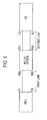
Fig. 2] Fig. 2 is a view showing a protocol stack to be used among a radio equipment device, a relay device, and a radio equipment controller which constitute the radio base station according to the first embodiment of the invention. - [
Fig. 3] Fig. 3 is a functional block diagram of the relay device according to the first embodiment of the invention. - [
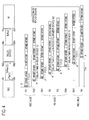
Fig. 4] Fig. 4 is a view for describing operation of the radio base station according to the first embodiment of the invention. - [
Fig. 5] Fig. 5 is a view for describing operation of a conventional radio base station. - [
Fig. 6] Fig. 6 is a view showing a terminated position of a synchronous signal in the conventional radio base station. - A radio base station according to the first embodiment of the invention will be described with reference to
Fig. 1 through Fig. 4 . - As shown in
Fig. 1 , a radio base station BTS according to the embodiment is provided with a radio equipment device RE, arelay device 10, and multiple radio equipment controllers REC#1,REC# 2. - Here, the radio equipment device RE, the
relay device 10, and the radio equipment controllers REC#1, REC#2 are separate devices, and connected to each other via a physical line such as an optical line, an electric line, or the like. For example, the radio equipment device RE, therelay device 10, and the radio equipment controllers REC#1, REC#2 are those specified by CPRI. - For example, the radio equipment controller REC#1 is a radio equipment controller REC for W-CDMA system, and the radio equipment controller REC#2 is a radio equipment controller REC for LTE system. Hereinafter, the radio equipment controllers REC#1 and REC#2 will be collectively referred to as the radio equipment controller REC.
- Here, a protocol stack to be used among the radio equipment device RE, the
relay device 10, and the radio equipment controller REC will be described with reference toFig. 2 . - As shown in
Fig. 2 , a configuration is such that aslayer 2 information, "user plane information," "control and management plane information," and "SYNC information (synchronous signal)" are transmitted and received in a first link between the radio equipment controller REC and therelay device 10, and a second link between therelay device 10 and the radio equipment device RE. - Specifically, in the frame to be transmitted and received over the first link and the second link, the user plane information is inserted in a user plane information area, the control and management plane information is inserted in a control and management plane information area, and the SYNC information (synchronous signal information) is inserted into a SYNC information area.
- In addition, the configuration is such that as
layer 2 information, "IQ data," "vendor specific data," "Ethernet ( Registered trademark) data," "HDLC data," "L1 inband protocol data," and the like are transmitted and received in the first link between the radio equipment controller REC and therelay device 10, and the second link between therelay device 10 and the radio equipment device RE. - Specifically, in the frame to be transmitted or received over the first link and the second link, the IQ data is inserted into an IQ data area, the vendor specific data is inserted into a vendor specific data area, the Ethernet (Registered trademark) data is inserted into an Ethernet (Registered trademark) data area, the HDLC data is inserted into an HDLC data area, and the L1 inband protocol data is inserted into an L1 inband protocol data area.
- Thus, each of the
layer 3 information and thelayer 2 information is configured to terminate in the first link and the second link. - As shown in
Fig. 3 , therelay device 10 is provided with a first synchronous signal reception unit 11, a second synchronoussignal transmission unit 12, a third synchronoussignal reception unit 13, a fourth synchronoussignal transmission unit 14, and a timing adjustment unit 15. - The first synchronous signal reception unit 11 is configured to extract a first synchronous signal from a predetermined position (SYNC information area) in a frame received from the radio equipment controller REC via the first link.
- The second synchronous
signal transmission unit 12 is configured to insert a second synchronous signal into the predetermined position (SYNC information area) in the frame and to transmit the second synchronous signal to the radio equipment device RE via the second link, in accordance with the first synchronous signal extracted by the first synchronous signal reception unit 11. - The third synchronous
signal reception unit 13 is configured to extract a third synchronous signal corresponding to the second synchronous signal mentioned above, from the predetermined position (SYNC information area) in the frame received from the radio equipment device RE via the second link. - The fourth synchronous
signal transmission unit 14 is configured to insert a fourth synchronous signal into the predetermined position (SYNC information area) in the frame and to transmit the fourth synchronous signal to the radio equipment controller REC via the first link, in accordance with the third synchronous signal extracted by the third synchronoussignal reception unit 13. - The timing adjustment unit 15 is configured to adjust transmission timing of the frame to be transmitted by the second synchronous
signal transmission unit 14, based on processing delay time in therelay device 10 and round-trip time RTT of the radio equipment device RE at therelay device 10. - Here, a method for adjusting transmission timing of the frame will be described with reference to
Fig. 4 . In addition, in an example ofFig. 4 , the predetermined position (SYNC information area) is assumed to be provided in an area A specified by BFN (NodeB Frame Number) #0 and HFN (Hyper Frame Number) #0 in the frame. - In
Fig. 4 , at time R1, the radio equipment controller REC inserts a first synchronous signal into the predetermined position (SYNC information area) in the frame and transmits the first synchronous signal to therelay device 10. At time RB2, the first synchronoussignal transmission unit 12 of therelay device 10 acquires the first synchronous signal from the predetermined position (SYNC information area) in the frame. Thus, a difference between the transmission time R1 of the first synchronous signal at the radio equipment controller REC and the reception time RB2 of the first synchronous signal at therelay device 10 is "T12(1)". - At time RB1, the second synchronous
signal transmission unit 12 of therelay device 10 inserts a second synchronous signal into the predetermined position (SYNC information area) in the frame and transmits the second synchronous signal to the radio equipment device RE. Thus, a difference between the reception time RB2 of the first synchronous signal at therelay device 10 and transmission time RB1 of the second synchronous signal at therelay device 10 is "delay time in therelay device 10". - At time R2, the radio equipment device RE acquires the second synchronous signal from the predetermined position (SYNC information area) in the frame. Thus, a difference between the transmission time RB1 of the second synchronous signal at the
relay device 10 and the reception time R2 of the second synchronous signal at the radio equipment device RE is "T12 (2)". - At time R3, the radio equipment device RE inserts a third synchronous signal into the predetermined position (SYNC information area) in the frame and transmits the third synchronous signal to the
relay device 10. Thus, a difference between the reception time R2 of the second synchronous signal at the radio equipment device RE and the transmission time R3 of the third synchronous signal at the radio equipment device RE is "delay time (Toffset) in the radio equipment device RE". - At time R4, the third synchronous
signal reception unit 13 of therelay device 10 acquires the third synchronous signal from the predetermined position (SYNC information area) in the frame. Thus, a difference between the transmission time R3 of the third synchronous signal at the radio equipment device RE and reception time RB4 of a third synchronized response signal at therelay device 10 is "T12(2)". - At time RB3, the fourth synchronous
signal transmission unit 14 of therelay device 10 inserts a fourth synchronous signal into the predetermined position (SYNC information area) in the frame and transmits the fourth synchronous signal to the radio equipment controller REC. Thus, a difference between the reception time RB4 of the third synchronous signal at therelay device 10 and the transmission time RB3 of the fourth synchronous signal at therelay device 10 is "delay time in therelay device 10". - At time R4, the radio equipment controller REC acquires the fourth synchronous signal from the predetermined position (SYNC information area) in the frame. Thus, a difference between the reception time RB3 of the fourth synchronous signal at the
relay device 10 and the transmission time R4 of the fourth synchronous signal at the radio equipment controller REC is "T12(1)". - As described above, a difference "T14" between the transmission time R1 of the first synchronous signal at the radio equipment controller REC and the reception time R4 of the fourth synchronous signal at the radio equipment controller REC is calculated from "T12 (1) " + "delay time in the
relay device 10" + "T12(2)" + "delay time (Toffset) in the radio equipment device RE" + "T12(2)" + "delay time in therelay device 10" + "T12 (1) ". - The difference "T14" corresponds to round-trip time RTT of the radio equipment device RE at the radio equipment controller REC.
- Here, the round-trip time RTT of the radio equipment device RE at the radio equipment controller REC is calculated from a difference between the transmission time R1 of the first synchronous signal at the radio equipment controller REC and the reception time R4 of the fourth synchronous signal at the radio equipment controller REC.
- Specifically, the radio equipment controller REC is summarized to be configured to calculate the round-trip time RTT of the radio equipment device RE at the radio equipment controller REC, based on the difference between the transmission time R1 of the first synchronous signal and the reception time R4 of the fourth synchronous signal.
- In addition, the round-trip time RTT of the radio equipment device RE at the
relay device 10 is calculated from a difference between the transmission time RB1 of the second synchronous signal at therelay device 10 and the reception time RB4 of the third synchronous signal at therelay device 10. - Specifically, the timing adjustment unit 15 is configured to calculate the round-trip time RTT of the radio equipment device RE at the
relay device 10, based on the difference between the transmission time RB1 of the second synchronous signal and the reception time RB4 of the third synchronous signal. - Specifically, the timing adjustment unit 15 may be configured to calculate total time ("delay time in the
relay device 10" + "T12 (2) " + "delay time (offset) in the radio equipment device RE" + "T12 (2) " + "delay time in therelay device 10") of processing time in therelay device 10 and the round-trip time RTT of the radio equipment device RE at therelay device 10 from the difference ("delay time in therelay device 10") between the reception time RB2 of the first synchronous signal and the transmission time RB1 of the second synchronous signal, the difference ("T12(2)" + "delay time (Toffset) in the radio equipment device RE" + "T12 (2) ") between the transmission time RB1 of the second synchronous signal and the reception time RB4 of the third synchronous signal, and the difference ("delay time in therelay device 10") between the reception time RB4 of the third synchronous signal and the transmission time RB3 of the fourth synchronous signal, and to delay transmission timing of the frame to be transmitted by the second synchronoussignal transmission unit 14 by the total time. Thus, by delaying the transmission timing of the frame, the round-trip time RTT of the radio equipment device RE can be accurately calculated without making any change to the radio equipment controller REC, even when there is any difference in the frame timing between the first link and the second link as shown inFig. 6 . - With the radio base station BTS according to the first embodiment of the invention, even if the
relay device 10 is provided, each radio equipmentcontroller REC# 1,REC# 2 can accurately calculate round-trip time RTT (T14) of the radio equipment device RE at each radio equipmentcontroller REC# 1,REC# 2, without being aware of presence of therelay device 10. - In addition, operation of the radio equipment device RE and the radio equipment controller REC described above may be implemented by hardware, may be implemented by a software module which is executed by a processor, or may be implemented by a combination thereof.
- The software module may be provided in a storage medium of any format such as a RAM (Random Access Memory), a flash memory, a ROM (Read Only Memory), an EPROM (Erasable Programmable ROM), an EEPROM (Electronically Erasable and Programmable ROM), a register, a hard disk drive, a removable disk, or a CD-ROM.
- The storage medium is connected to a processor so that the processor can read and write information from/into the storage medium. In addition, the storage medium may be integrated in the processor. Furthermore, the storage medium and processor may be provided in an ASIC. The ASIC may be provided in the radio equipment device RE and the radio equipment controller REC. In addition, the storage medium and processor may be provided in the radio equipment device RE and the radio equipment controller REC as a discrete component.
- Although the invention has been described in detail by using the embodiment mentioned above, it is apparent to those skilled in the art that the invention is not limited to the embodiment described in the specification. The invention can be carried out as a modification and changed mode, without deviating from the intent and scope of the invention defined by the Claims. Therefore, the description of the specification is intended to provide exemplification and description, and does not have any limiting meaning to the invention.
- In addition, Japanese Patent Application No.
2009-287723 (filed on December 18, 2009 - With the invention, even if a relay device is provided, a ratio base station and the relay device which can accurately calculate round-trip time of a radio equipment device RE at each radio equipment controller REC can be provided. Therefore, the invention is useful in radio communications and the like.
-
- RE
- Radio equipment device
- REC
- Radio equipment controller
- 10
- Relay device
- 11
- Synchronization request signal reception unit
- 12
- Synchronization request signal transmission unit
- 13
- Synchronization response signal reception unit
- 14
- Synchronization response signal transmission unit
- 15
- Timing adjustment unit
Claims (4)
- A radio base station comprising a radio equipment controller, a relay device, and a radio equipment device which are connected via a physical line, wherein
a synchronous signal, which is inserted into a predetermined position in a frame and transmitted, is configured to terminate at a first link between the radio equipment controller and the relay device and to terminate at a second link between the relay device and the radio equipment device,
the relay device comprises:a first synchronous signal reception unit configured to extract a first synchronous signal from a predetermined position in a frame received from the radio equipment controller via the first link;a second synchronous signal transmission unit configured to insert a second synchronous signal into the predetermined position of the frame and to transmit the second synchronous signal to the radio equipment device via the second link, in accordance with the extracted first synchronous signal;a third synchronous signal reception unit configured to extract a third synchronous signal from the predetermined position in the frame received from the radio equipment device via the second link;a fourth synchronous signal transmission unit configured to insert a fourth synchronous signal into the predetermined position in the frame and to transmit the fourth synchronous signal to the radio equipment controller via the second link, in accordance with the extracted third synchronous signal; anda timing adjustment unit configured to adjust transmission timing of the frame to be transmitted by the second synchronous signal transmission unit, based on processing delay time in the relay device and round-trip time of the radio equipment device at the relay device, andthe radio equipment controller is configured to calculate round-trip response time of the radio equipment device at the radio equipment controller, based on a difference between transmission time of the first synchronous signal and reception time of the fourth synchronous signal. - The radio base station according to claim 1, wherein the timing adjustment unit is configured to calculate a total time of processing delay time in the relay device and round-trip time of the radio equipment device at the relay device, from a difference between reception time of the first synchronous signal and transmission time of the second synchronous signal, a difference between the transmission time of the second synchronous signal and reception time of the third synchronous signal, and a difference between the reception time of the third synchronous signal and transmission time of the fourth synchronous signal, and to delay the transmission timing of the frame to be transmitted by the second synchronous signal transmission unit, by the total time.
- A relay device connected to a radio equipment controller and a radio equipment device via a physical line and provided in a radio base station, wherein
a synchronous signal, which is inserted into a predetermined position in a frame and transmitted, is configured to terminate at a first link between the radio equipment controller and the relay device and to terminate at a second link between the relay device and the radio equipment device, and
the relay device comprises:a first synchronous signal reception unit configured to extract a first synchronous signal from a predetermined position in a frame received from the radio equipment controller via the first link;a second synchronous signal transmission unit configured to insert a second synchronous signal into the predetermined position in the frame and to transmit the second synchronous signal to the radio equipment device via the second link, in accordance with the extracted first synchronous signal;a third synchronous signal reception unit configured to extract a third synchronous signal from the predetermined position in the frame received from the radio equipment device via the second link;a fourth synchronous signal transmission unit configured to insert a fourth synchronous signal into the predetermined position in the frame and to transmit the fourth synchronous signal to the radio equipment controller via the first link, in accordance with the extracted third synchronous signal; anda timing adjustment unit configured to adjust transmission timing of the frame to be transmitted by the second synchronous signal transmission unit, based on processing delay time in the relay device and round-trip time of the radio equipment device at the relay device. - The relay device according to claim 3, wherein the timing adjustment unit is configured to calculate a total time of processing delay time in the relay device and the round-time delay time in the relay device, from a difference between reception time of the first synchronous signal and transmission time of the second synchronous signal, a difference between the transmission time of the second synchronous signal and reception time of the third synchronous signal, and a difference between the reception time of the third synchronous signal and transmission time of the fourth synchronous signal, and to delay the transmission timing of the frame to be transmitted by the second synchronous signal transmission unit, by the total time.
Applications Claiming Priority (2)
| Application Number | Priority Date | Filing Date | Title |
|---|---|---|---|
| JP2009287723 | 2009-12-18 | ||
| PCT/JP2010/072763 WO2011074664A1 (en) | 2009-12-18 | 2010-12-17 | Wireless base station, and relay device |
Publications (1)
| Publication Number | Publication Date |
|---|---|
| EP2515590A1 true EP2515590A1 (en) | 2012-10-24 |
Family
ID=44167414
Family Applications (1)
| Application Number | Title | Priority Date | Filing Date |
|---|---|---|---|
| EP10837688A Withdrawn EP2515590A1 (en) | 2009-12-18 | 2010-12-17 | Wireless base station, and relay device |
Country Status (5)
| Country | Link |
|---|---|
| US (1) | US20120307712A1 (en) |
| EP (1) | EP2515590A1 (en) |
| JP (1) | JPWO2011074664A1 (en) |
| CN (1) | CN102656931A (en) |
| WO (1) | WO2011074664A1 (en) |
Cited By (4)
| Publication number | Priority date | Publication date | Assignee | Title |
|---|---|---|---|---|
| WO2018080368A1 (en) * | 2016-09-06 | 2018-05-03 | Telefonaktiebolaget Lm Ericsson (Publ) | Configuration of a radio equipment of an access node |
| US10524273B2 (en) | 2016-09-06 | 2019-12-31 | Telefonaktiebolaget Lm Ericsson (Publ) | Resource configuration of wireless devices |
| US11063795B2 (en) | 2016-11-16 | 2021-07-13 | Telefonaktiebolaget Lm Ericsson (Publ) | Methods and devices for adapting load on a fronthaul network |
| US11128322B2 (en) | 2016-09-06 | 2021-09-21 | Telefonaktiebolaget Lm Ericsson (Publ) | Methods and devices for determination of beamforming information |
Families Citing this family (18)
| Publication number | Priority date | Publication date | Assignee | Title |
|---|---|---|---|---|
| WO2010044142A1 (en) * | 2008-10-14 | 2010-04-22 | 富士通株式会社 | Relay device, relay method and relay program |
| US9883471B2 (en) * | 2011-06-13 | 2018-01-30 | Telefonaktiebolaget Lm Ericsson (Publ) | Method and device for rate matching |
| JP5899687B2 (en) * | 2011-07-15 | 2016-04-06 | ソニー株式会社 | COMMUNICATION DEVICE AND COMMUNICATION METHOD, COMMUNICATION SYSTEM, AND COMPUTER PROGRAM |
| US20130121240A1 (en) * | 2011-11-16 | 2013-05-16 | Telefonaktiebolaget L M Ericsson (Publ) | Delay Management in Shared Baseband Deployments |
| WO2014037061A1 (en) * | 2012-09-06 | 2014-03-13 | Telefonaktiebolaget L M Ericsson (Publ) | Use of common public radio interface over asymmetric networks |
| JP5791828B2 (en) * | 2012-11-28 | 2015-10-07 | 三菱電機株式会社 | Relay device, communication system, and relay method |
| US9456344B2 (en) * | 2013-03-15 | 2016-09-27 | Ologn Technologies Ag | Systems, methods and apparatuses for ensuring proximity of communication device |
| US9698991B2 (en) | 2013-03-15 | 2017-07-04 | Ologn Technologies Ag | Systems, methods and apparatuses for device attestation based on speed of computation |
| US10177915B2 (en) | 2013-03-15 | 2019-01-08 | Ologn Technologies Ag | Systems, methods and apparatuses for device attestation based on speed of computation |
| EP2995061B1 (en) | 2013-05-10 | 2018-04-18 | OLogN Technologies AG | Ensuring proximity of wifi communication devices |
| US9455998B2 (en) | 2013-09-17 | 2016-09-27 | Ologn Technologies Ag | Systems, methods and apparatuses for prevention of relay attacks |
| US9204312B2 (en) * | 2013-11-27 | 2015-12-01 | Freescale Semiconductor, Inc. | Method for adding leaf node to multi-node base station |
| JP6362779B2 (en) * | 2015-07-02 | 2018-07-25 | 三菱電機株式会社 | Base station, mobile communication system, and delay correction method |
| CN110505636A (en) * | 2018-11-29 | 2019-11-26 | 中国电子科技集团公司第七研究所 | Synchronous control method for relay communication |
| CN113766627B (en) * | 2020-03-11 | 2023-07-18 | 海能达通信股份有限公司 | Signal sending and processing method and device |
| JP7421970B2 (en) * | 2020-03-25 | 2024-01-25 | 株式会社Nttドコモ | Communication device |
| TWI769046B (en) * | 2021-08-10 | 2022-06-21 | 瑞昱半導體股份有限公司 | Signal relay apparatus and method having frequency calibration mechanism |
| US12135367B2 (en) * | 2021-12-08 | 2024-11-05 | Verizon Patent And Licensing Inc. | Methods and systems for locating a user equipment device based on signal travel time and bias suppression |
Family Cites Families (24)
| Publication number | Priority date | Publication date | Assignee | Title |
|---|---|---|---|---|
| JP3049461B2 (en) * | 1993-04-20 | 2000-06-05 | 日立電子株式会社 | Wireless relay method and device |
| GB2301734B (en) * | 1995-05-31 | 1999-10-20 | Motorola Ltd | Communications system and method of operation |
| JP3769468B2 (en) * | 2001-03-21 | 2006-04-26 | 株式会社エヌ・ティ・ティ・ドコモ | Communication quality control method, communication quality control system, packet analysis device, and data transmission terminal device |
| US8908650B2 (en) * | 2004-10-12 | 2014-12-09 | Telefonaktiebolaget Lm Ericsson (Publ) | Interface, apparatus, and method for communication between a radio equipment control node and one or more remote radio equipment nodes |
| DE102004055975B4 (en) * | 2004-11-19 | 2007-05-03 | Bosch Rexroth Ag | Synchronization method and control system for the timing synchronization of slave units, as well as time-synchronizable slave unit |
| WO2006087788A1 (en) * | 2005-02-17 | 2006-08-24 | Fujitsu Limited | Packet relaying apparatus and packet relaying method |
| JP4627669B2 (en) * | 2005-03-16 | 2011-02-09 | アラクサラネットワークス株式会社 | Packet transfer apparatus and transfer control method thereof |
| JP2007081678A (en) * | 2005-09-13 | 2007-03-29 | Ntt Docomo Inc | Data relay apparatus and data relay method |
| US7602873B2 (en) * | 2005-12-23 | 2009-10-13 | Agilent Technologies, Inc. | Correcting time synchronization inaccuracy caused by asymmetric delay on a communication link |
| JP4981494B2 (en) * | 2006-05-30 | 2012-07-18 | 株式会社日立国際電気 | Wireless communication system and overhang station apparatus |
| CN101102131A (en) * | 2006-07-03 | 2008-01-09 | 中兴通讯股份有限公司 | Transmission delay measurement method of remote radio frequency unit |
| JP2008022144A (en) * | 2006-07-11 | 2008-01-31 | Toshiba Corp | Optical transmission system and its delay time measurement method |
| EP2063571A1 (en) * | 2006-09-13 | 2009-05-27 | Panasonic Corporation | Communication device |
| US20080069150A1 (en) * | 2006-09-19 | 2008-03-20 | Sig Harold Badt | Precision Time Protocol Emulation for Network Supportive of Circuit Emulation Services |
| US20080175275A1 (en) * | 2007-01-22 | 2008-07-24 | Samsung Electronics Co., Ltd. | Time synchronization method between nodes in network and apparatus for implementing the same |
| JP4816957B2 (en) * | 2007-03-07 | 2011-11-16 | 日本電気株式会社 | Relay device, route selection system, route selection method, and program |
| WO2009088937A2 (en) * | 2008-01-02 | 2009-07-16 | Interdigital Technology Corporation | Method and apparatus for cooperative wireless communications |
| JP5145991B2 (en) * | 2008-02-07 | 2013-02-20 | 富士通株式会社 | Wireless relay station |
| US8050296B2 (en) * | 2008-03-31 | 2011-11-01 | Telefonaktiebolaget Lm Ericsson (Publ) | Radio equipment (RE)-based synchronization |
| JP5024960B2 (en) | 2008-05-30 | 2012-09-12 | 学校法人千葉工業大学 | Reciprocating rocking mechanism and flapping airplane using the same |
| JP5120454B2 (en) * | 2008-07-30 | 2013-01-16 | 富士通株式会社 | Data relay apparatus and frame processing method using the data relay apparatus |
| JP5228714B2 (en) * | 2008-09-02 | 2013-07-03 | 富士通株式会社 | Time synchronization method and relay device |
| CN101389090A (en) * | 2008-10-09 | 2009-03-18 | 深圳国人通信有限公司 | Optical fiber repeater, time delay measurement method, device thereof, and compensation method, system |
| JP5125988B2 (en) * | 2008-10-23 | 2013-01-23 | 富士通株式会社 | Wireless relay device |
-
2010
- 2010-12-17 CN CN2010800574538A patent/CN102656931A/en active Pending
- 2010-12-17 JP JP2011546181A patent/JPWO2011074664A1/en active Pending
- 2010-12-17 EP EP10837688A patent/EP2515590A1/en not_active Withdrawn
- 2010-12-17 US US13/516,868 patent/US20120307712A1/en not_active Abandoned
- 2010-12-17 WO PCT/JP2010/072763 patent/WO2011074664A1/en not_active Ceased
Non-Patent Citations (1)
| Title |
|---|
| See references of WO2011074664A1 * |
Cited By (9)
| Publication number | Priority date | Publication date | Assignee | Title |
|---|---|---|---|---|
| WO2018080368A1 (en) * | 2016-09-06 | 2018-05-03 | Telefonaktiebolaget Lm Ericsson (Publ) | Configuration of a radio equipment of an access node |
| US10420122B2 (en) | 2016-09-06 | 2019-09-17 | Telefonaktiebolaget Lm Ericsson (Publ) | Configuration of resolution of uplink data |
| US10524273B2 (en) | 2016-09-06 | 2019-12-31 | Telefonaktiebolaget Lm Ericsson (Publ) | Resource configuration of wireless devices |
| US10524274B2 (en) | 2016-09-06 | 2019-12-31 | Telefonaktiebolaget Lm Ericsson (Publ) | Configuration of a radio equipment of an access node |
| US10820334B2 (en) | 2016-09-06 | 2020-10-27 | Telefonaktiebolaget Lm Ericsson (Publ) | Configuration of resolution of uplink data |
| US11128322B2 (en) | 2016-09-06 | 2021-09-21 | Telefonaktiebolaget Lm Ericsson (Publ) | Methods and devices for determination of beamforming information |
| US11206675B2 (en) | 2016-09-06 | 2021-12-21 | Telefonaktiebolaget Lm Ericsson (Publ) | Configuration of transmission order of uplink data |
| US11690059B2 (en) | 2016-09-06 | 2023-06-27 | Telefonaktiebolaget Lm Ericsson (Publ) | Configuration of transmission order of uplink data |
| US11063795B2 (en) | 2016-11-16 | 2021-07-13 | Telefonaktiebolaget Lm Ericsson (Publ) | Methods and devices for adapting load on a fronthaul network |
Also Published As
| Publication number | Publication date |
|---|---|
| CN102656931A (en) | 2012-09-05 |
| JPWO2011074664A1 (en) | 2013-05-02 |
| US20120307712A1 (en) | 2012-12-06 |
| WO2011074664A1 (en) | 2011-06-23 |
Similar Documents
| Publication | Publication Date | Title |
|---|---|---|
| EP2515590A1 (en) | Wireless base station, and relay device | |
| CN101926146B (en) | Flexible time stamping | |
| US9830298B2 (en) | Media time based USB frame counter synchronization for Wi-Fi serial bus | |
| US8582494B2 (en) | Data relay device and frame processing method by the same | |
| CN100499402C (en) | Mobile communication system, radio control apparatus, and base station | |
| EP1890403A3 (en) | Radio relay communication method, radio base station and radio relay station in radio communication system | |
| EP3057363B1 (en) | Timing advance adjustment method and device | |
| CN103999521B (en) | Delay compensation during being synchronized in base station in a cellular communication network | |
| EP2833683B1 (en) | Time synchronization method and system using wifi-direct | |
| US20160262120A1 (en) | Wireless synchronization based on beacons | |
| CN101098328A (en) | A baseband and radio frequency system synchronization and delay compensation method | |
| CN105325037A (en) | Synchronization method, synchronization device and base station | |
| US20170127363A1 (en) | Transmission system, wireless device, and synchronization establishment method | |
| CN103152118A (en) | Base band unit and remote radio unit data service synchronization method, device and system | |
| EP2114104A3 (en) | Method to estimate multiple round trip delays attached to cellular terminals from a RACH signal received within a dedicated time slot multiplexed onto an uplink traffic multiplex frame. | |
| WO2010095851A2 (en) | Method and apparatus for communication between relay node and user equipment in wireless communication system | |
| JP4853625B2 (en) | Propagation delay time measuring method, synchronization method, and wireless LAN system | |
| RU2015136450A (en) | TEMPORARY SIGNAL SYNCHRONIZATION IN CONNECTION OF THE DEVICE WITH THE DEVICE | |
| JP5351790B2 (en) | Communication system and communication control method | |
| EP2515605A1 (en) | Wireless base station system, and relay device | |
| EP2523489A1 (en) | Mobile communication method, mobile station, and relay node | |
| US20100316020A1 (en) | Communication system, mobile terminal and communication method | |
| CN104469885A (en) | Scheduling method and related electronic device | |
| CN101754250B (en) | Channel measuring method and system | |
| JP2008244666A (en) | Mobile wireless communication system |
Legal Events
| Date | Code | Title | Description |
|---|---|---|---|
| PUAI | Public reference made under article 153(3) epc to a published international application that has entered the european phase |
Free format text: ORIGINAL CODE: 0009012 |
|
| 17P | Request for examination filed |
Effective date: 20120709 |
|
| AK | Designated contracting states |
Kind code of ref document: A1 Designated state(s): AL AT BE BG CH CY CZ DE DK EE ES FI FR GB GR HR HU IE IS IT LI LT LU LV MC MK MT NL NO PL PT RO RS SE SI SK SM TR |
|
| DAX | Request for extension of the european patent (deleted) | ||
| STAA | Information on the status of an ep patent application or granted ep patent |
Free format text: STATUS: THE APPLICATION HAS BEEN WITHDRAWN |
|
| 18W | Application withdrawn |
Effective date: 20131030 |