EP2515436A1 - MEMS resonator and method of controlling the same - Google Patents
MEMS resonator and method of controlling the same Download PDFInfo
- Publication number
- EP2515436A1 EP2515436A1 EP11162888A EP11162888A EP2515436A1 EP 2515436 A1 EP2515436 A1 EP 2515436A1 EP 11162888 A EP11162888 A EP 11162888A EP 11162888 A EP11162888 A EP 11162888A EP 2515436 A1 EP2515436 A1 EP 2515436A1
- Authority
- EP
- European Patent Office
- Prior art keywords
- resonator
- axis direction
- connecting arm
- vibration
- transverse
- Prior art date
- Legal status (The legal status is an assumption and is not a legal conclusion. Google has not performed a legal analysis and makes no representation as to the accuracy of the status listed.)
- Withdrawn
Links
- 238000000034 method Methods 0.000 title claims description 9
- 238000013016 damping Methods 0.000 claims description 3
- 238000001514 detection method Methods 0.000 claims description 2
- 238000013461 design Methods 0.000 description 16
- 230000003071 parasitic effect Effects 0.000 description 13
- 239000000758 substrate Substances 0.000 description 8
- 238000005259 measurement Methods 0.000 description 6
- 238000005452 bending Methods 0.000 description 5
- 239000000725 suspension Substances 0.000 description 5
- 230000008859 change Effects 0.000 description 4
- 230000008901 benefit Effects 0.000 description 3
- 230000000694 effects Effects 0.000 description 3
- XUIMIQQOPSSXEZ-UHFFFAOYSA-N Silicon Chemical compound [Si] XUIMIQQOPSSXEZ-UHFFFAOYSA-N 0.000 description 2
- 230000004044 response Effects 0.000 description 2
- 229910052710 silicon Inorganic materials 0.000 description 2
- 239000010703 silicon Substances 0.000 description 2
- JBRZTFJDHDCESZ-UHFFFAOYSA-N AsGa Chemical compound [As]#[Ga] JBRZTFJDHDCESZ-UHFFFAOYSA-N 0.000 description 1
- 229910001218 Gallium arsenide Inorganic materials 0.000 description 1
- 238000013459 approach Methods 0.000 description 1
- 230000006835 compression Effects 0.000 description 1
- 238000007906 compression Methods 0.000 description 1
- 239000004035 construction material Substances 0.000 description 1
- 230000001419 dependent effect Effects 0.000 description 1
- 239000003989 dielectric material Substances 0.000 description 1
- 230000005489 elastic deformation Effects 0.000 description 1
- 238000005530 etching Methods 0.000 description 1
- 230000002349 favourable effect Effects 0.000 description 1
- 239000011521 glass Substances 0.000 description 1
- 238000003780 insertion Methods 0.000 description 1
- 230000037431 insertion Effects 0.000 description 1
- 230000003993 interaction Effects 0.000 description 1
- 238000001459 lithography Methods 0.000 description 1
- 238000004519 manufacturing process Methods 0.000 description 1
- 229910052751 metal Inorganic materials 0.000 description 1
- 239000007769 metal material Substances 0.000 description 1
- 238000001000 micrograph Methods 0.000 description 1
- 238000012986 modification Methods 0.000 description 1
- 230000004048 modification Effects 0.000 description 1
- 230000003287 optical effect Effects 0.000 description 1
- 230000010355 oscillation Effects 0.000 description 1
- 239000010453 quartz Substances 0.000 description 1
- 229920006395 saturated elastomer Polymers 0.000 description 1
- 239000004065 semiconductor Substances 0.000 description 1
- VYPSYNLAJGMNEJ-UHFFFAOYSA-N silicon dioxide Inorganic materials O=[Si]=O VYPSYNLAJGMNEJ-UHFFFAOYSA-N 0.000 description 1
- 238000012546 transfer Methods 0.000 description 1
Images




Classifications
-
- H—ELECTRICITY
- H03—ELECTRONIC CIRCUITRY
- H03H—IMPEDANCE NETWORKS, e.g. RESONANT CIRCUITS; RESONATORS
- H03H9/00—Networks comprising electromechanical or electro-acoustic elements; Electromechanical resonators
- H03H9/02—Details
- H03H9/02244—Details of microelectro-mechanical resonators
- H03H9/02433—Means for compensation or elimination of undesired effects
-
- H—ELECTRICITY
- H03—ELECTRONIC CIRCUITRY
- H03H—IMPEDANCE NETWORKS, e.g. RESONANT CIRCUITS; RESONATORS
- H03H9/00—Networks comprising electromechanical or electro-acoustic elements; Electromechanical resonators
- H03H9/02—Details
- H03H9/02244—Details of microelectro-mechanical resonators
- H03H9/02338—Suspension means
-
- H—ELECTRICITY
- H03—ELECTRONIC CIRCUITRY
- H03H—IMPEDANCE NETWORKS, e.g. RESONANT CIRCUITS; RESONATORS
- H03H9/00—Networks comprising electromechanical or electro-acoustic elements; Electromechanical resonators
- H03H9/24—Constructional features of resonators of material which is not piezoelectric, electrostrictive, or magnetostrictive
- H03H9/2405—Constructional features of resonators of material which is not piezoelectric, electrostrictive, or magnetostrictive of microelectro-mechanical resonators
- H03H9/2447—Beam resonators
- H03H9/2452—Free-free beam resonators
-
- H—ELECTRICITY
- H03—ELECTRONIC CIRCUITRY
- H03H—IMPEDANCE NETWORKS, e.g. RESONANT CIRCUITS; RESONATORS
- H03H9/00—Networks comprising electromechanical or electro-acoustic elements; Electromechanical resonators
- H03H9/02—Details
- H03H9/02244—Details of microelectro-mechanical resonators
- H03H9/02433—Means for compensation or elimination of undesired effects
- H03H2009/02456—Parasitic elements or effects, e.g. parasitic capacitive coupling between input and output
-
- H—ELECTRICITY
- H03—ELECTRONIC CIRCUITRY
- H03H—IMPEDANCE NETWORKS, e.g. RESONANT CIRCUITS; RESONATORS
- H03H9/00—Networks comprising electromechanical or electro-acoustic elements; Electromechanical resonators
- H03H9/02—Details
- H03H9/02244—Details of microelectro-mechanical resonators
- H03H2009/02488—Vibration modes
Definitions
- This invention relates to resonators, for example MEMS resonators.
- MEMS resonators are replacing quartz resonators as reference timing devices; they serve as reference resonators in oscillator circuits or as clocking reference to synchronise operations in digital circuitry.
- MEMS resonators offer the advantage of small dimensions (especially the small height is considered an advantage) with low-cost fabrication.
- MEMS resonators can also be combined to form a high-quality filter.
- MEMS resonators should meet the same demands for different reasons:
- MEMS resonators exhibit a limit to the amplitude of the resonant oscillations which is below that which would be expected from the mechanical design.
- the origin of this limitation has only been fully understood very recently, and relates to the transfer of energy from the desired mode of vibration (eigenmode) to other eigenmodes.
- a resonator comprising a resonator body and actuation electrodes for driving the resonator into a resonant mode, in which the resonator body vibrates parallel to a first axis; and a detection arrangement for detecting the vibration in the first axis direction and generating an electrical output signal derived from the vibration, wherein the resonator comprises a first anchor arrangement at which the resonator is fixed in position, wherein the first anchor arrangement connects to the resonator body at a nodal point where no movement is induced by the vibration, and wherein the resonator comprises a second anchor arrangement, and a connecting arm between the resonator body and the second anchor arrangement, wherein the connecting arm connects to the resonator body at a non-nodal point.
- the invention enables the stable operation of the principal vibration mode (such as the length-extensional vibration mode) of a MEMS resonator to be extended.
- the principal vibration mode such as the length-extensional vibration mode
- this mode cannot be brought to vibrate more strongly.
- the cause is that parasitic out-of-plane modes are excited at this point. These parasitic modes have a transversal vibration component.
- the invention uses additional anchor points and connecting arms that are designed not to hamper the principal vibration mode, but which are designed to suppress or restrict all other vibrations.
- connection arms can be thought of as guides in that they limit the movement in one direction but permit free movement along the principal vibration axis.
- the connecting arm can have the same matched resonant frequency as the resonator mass for vibrations in the first axis direction, but a non-matched resonant frequency for vibrations in a transverse direction.
- the invention results in a structure in which the resonator is attached to the fixed external surroundings at more points than only the nodal (e.g. central) region.
- the connecting arm extends from the resonator body in a direction transverse to the first axis direction.
- the resonator body has two free ends and the first anchor arrangement connects to the resonator body centrally between the two free ends, and one or more connecting arms connect to each free end. This gives a symmetrical arrangement for known length-extensional resonators with two free ends.
- the resonator body can for example comprise a pair of expansion arms which extend along the first axis direction, with a head at each end of the pair of expansion arms, wherein the first anchor arrangement connects to the middle of the expansion arms and the connecting arm connects to the head.
- This is an arrangement of the invention applied to a so-called dog-bone resonator.
- a first connecting arm can extend outwardly in a first direction transverse to the first axis direction from one head, a second connecting arm extending outwardly in a second opposite direction transverse to the first axis direction from the one head, a third connecting arm extending outwardly in the first direction transverse to the first axis direction from the other head and a fourth connecting arm extending outwardly in the second opposite direction transverse to the first axis direction from the other head.
- first pair of connecting arms extending outwardly in a first direction transverse to the first axis direction from one head
- a second pair of connecting arms extending outwardly in a second opposite direction transverse to the first axis direction from the one head
- a third pair of connecting arms extending outwardly in the first direction transverse to the first axis direction from the other head
- a fourth pair of connecting arms extending outwardly in the second opposite direction transverse to the first axis direction from the other head.
- the or each connecting arm can have a first portion transverse to the first axis direction, a second portion parallel to the first axis direction and a third portion transverse to the first axis direction.
- This Z shaped design reduces stresses induced in the resonator.
- the invention also provides a method of controlling a resonator which comprises a resonator body and actuation electrodes for driving the resonator into a resonant mode, in which the resonator body vibrates parallel to a first axis, the method comprising:
- MEMS resonators are designed such that an actuation signal excites one of the resonator's eigenmodes.
- Figure 1 shows a resonator designed to vibrate in a length-extensional mode when an ac actuation voltage is applied. If properly designed, the actuation signal does not excite other modes (like bending modes or torsion modes in this example).
- FIG. 1 The design shown in Figure 1 is a known piezoresistive MEMS resonator, which is described in more detail in WO 2004/053431 .
- the resonator 1 shown in Figure 1 comprises a substrate 10 which is a silicon wafer.
- the substrate 10 may be a gallium arsenide wafer or it may comprise any other semiconducting, metal or dielectric material.
- a substrate 10 comprising a dielectric such as, e. g. glass, because this reduces the loss of electromagnetic energy dissipated in the substrate.
- the resonator 1 further comprises an electrically conductive resonator element 20 having two parallel connecting elements 20a,20b.
- the resonator extends in a longitudinal direction having a length I along a first axis which is the axis along which the intended vibrations arise, for operation in bulk mode. It is attached to the substrate 10 via support elements 21 and 22 which are connected to anchor elements 23 and 24, respectively.
- the anchor elements 23 and 24 are affixed to the substrate 10.
- the resonator element 20 and the support elements 21 and 22 are free from the substrate 10 except for the connection via the anchor elements 23 and 24.
- the resonator element 20 has two outer ends 205 in the longitudinal direction. These can be larger than the combined width of the connecting beams 20a,20b and spacing 19 to define wider resonator masses at the ends, and thereby define a so-called dog-bone shape. This is shown in Figure 2 .
- each of the outer ends 205 is faced by a respective electrode of the electrically conductive actuator 30, and is spaced from the electrode by an actuation gap g.
- the actuators can be considered to be gate terminals, in that the control input is applied to these terminals.
- the actuator 30 is able to receive an actuation potential difference VIN with respect to the resonator element 20 for elastically deforming the resonator element 20, using the electrostatic force.
- the actuation potential difference is a function of the input signal applied to the resonator 1.
- the actuation potential difference may typically further contain a DC component.
- the elastic deformation comprises a change of the length I by an amount dl shown in Fig. 1 .
- a feedback system controls the frequency of the actuation voltage, and the feedback loop stabilises at resonance with the actuation voltage frequency the same as the physical resonant frequency of the resonator.
- the resonator element 20 is part of an oscillator circuit which is able to conduct an electrical current through the resonator element 20.
- the resonator element 20 is electrically connected to the positive or negative pole of a DC voltage source VDC via an auxiliary resistor 27, the anchor element 24 and the support element 22.
- the anchor 24 can be considered to be a drain terminal in that the DC voltage bias is applied to this terminal to drive a bias current through the device.
- the resonator element 20 is further connected to ground via the support element 21 and the anchor element 23.
- the anchor 23 can be considered to be a source terminal in that the bias current is collected at this terminal. Therefore, the resonator element 20 is able to conduct an electrical current I. It constitutes a resistor with an ohmic resistance R which causes a voltage drop V when the resonator element 20 conducts the electrical current I.
- the resonator element 20 constitutes a resistor with an ohmic resistance R which is a function of the change dl of the length I because the resonator element 20 comprises a central part 19 with open space.
- the resonator element 20 comprises the two mutually parallel beams 20a,20b each of which is affixed to a respective support element 21 and 22. The two beams are connected with each other at the two outer ends by elements 205.
- the central part 19 has been created during a lithography step and etching step. It prevents the current from flowing from the support element 22 to the support element 21 in a straight line. The current has to follow the conductive path formed by the resonator element 20. This conductive path extends in the longitudinal direction.
- the circuit is able to produce an output signal which is a function of the change dl of the length I and which is a function of the resistance R.
- the circuit comprises a measurement point 28 which is electrically connected to the circuit. It is situated between the auxiliary resistor 27 and the anchor element 24, and in operation it produces an electrical output signal which is the electrical potential difference Vout between the measurement point 28 and the reference point 29 which is connected to ground.
- the auxiliary resistor 27 is not situated between the voltage source and the anchor element 24, but instead between the anchor element 23 and ground. In this case the measurement point 28 is situated between the auxiliary resistor 27 and the anchor element 23.
- the DC voltage source VDC and the auxiliary resistor 27 are omitted.
- the anchor element 24 is connected to the positive pole of a current source and the anchor element 23 is connected to the negative pole of the current source.
- the measurement point 28 is situated between the positive pole of the current source and the anchor element 24, and the reference point 29 is situated between the anchor element 23 and the negative pole of the current source.
- the output signal is again a function of the change dl of the length I as will be understood by those skilled in the art.
- sensing using current bias or voltage bias can be employed.
- the resulting mechanical resonance is in-plane of the drawing and is symmetrical.
- the left and right parts of the resonator can be enlarged to define masses of relatively larger stiffness than the intermediate beams, so the compression and expansion that cause the resonator-vibration occurs in the beams.
- the so called actuation-gap on each side is located between the gate electrodes 30 and the resonator mass and is in the order of a few hundred nm.
- the resonator may be manufactured using a technique well known in the field of micro electromechanical systems (MEMS).
- MEMS micro electromechanical systems
- FIG. 3 A plot of the vibration amplitude versus the actuation frequency is shown in Figure 3 .
- the resonator has a vibration amplitude which has a peak at a specific resonant frequency.
- the MEMS resonator is a purely linear device: if the actuation voltage doubles then the vibration amplitude doubles. Unfortunately, amplitude saturation is observed, meaning that the peak of the vibration amplitude peak is limited to a fixed level. This is shown in Figure 4 , which shows the amplitude plots of Figure 3 (vibration amplitude vs. actuation frequency) for different actuation voltages. The actuation level is expressed in dBm, providing a measure of signal power.
- the parasitic mode drains energy from the desired length-extensional mode.
- An increase in actuation amplitude does not lead to an increased amplitude of the desired mode, but rather to an increase of amplitude of the parasitic mode.
- This effect is called autoparametric resonance and is discussed in C van der Avoort et al "Amplitude saturation of MEMS resonators explained by autoparametric resonance" 2010 J. Micromech. Microeng. 20 105012 .
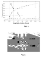
- FIG. 5 shows actual measurements of saturation.
- the electrical output generated by the longitudinal vibration (plot 50) is saturated at a certain point.
- Optical vibration measurements of the out-of-plane vibration are shown as plot 52. These occur at the eigenfrequency for the out-of-plane mode, which is different from the driven longitudinal mode. This shows an increasing amplitude of this mode as the driving level is further increased.
- the principal mode is a length-extension mode
- the parasitic modes involved are bending or torsion modes or combinations of them. In either of these modes there is a transversal (i.e. out-of-plane) vibration component.
- the energy drainage due to autoparametric resonance occurs even for relatively small length-extensional vibration amplitudes if the operation frequency of the resonator (i.e. the actuation frequency) exactly matches the eigenfrequency of the parasitic mode.
- the MEMS resonator does not meet the demand of having a non-distorted large amplitude output signal.
- a method is therefore desired to simultaneously suppress all unwanted out-of-plane modes.
- the invention provides a resonator in which in addition to the normal anchor at a nodal point, a second anchor arrangement is provided and an associated connecting arm between the resonator body and the second anchor arrangement.
- the connecting arm connects to the resonator body at a non-nodal point so that it is not connected to a normal position where fixed connections are made.
- the connecting arm connects to the second anchor arrangement at a nodal point of the vibrations of the combined resonator mass and connecting arm. This means that the second anchor can be considered as at a nodal point of the combination of the connecting arm and the resonator mass. They can together have the same resonant frequency as the resonator mass alone (without the connecting arm) so that the desired resonance is not damped.
- the invention is based on suppressing a transverse mode, e.g. a bending mode, so that the critical value can be shifted and the regular response of the principal vibration mode can achieve larger values. It is known that the suspension of a resonator at a nodal point of the vibration mode is favourable for the quality factor of the resonator, i.e. the resonator will show low damping or dissipative losses.
- the invention is based on altering the resonator structure, to maintain the desired requirement that in the desired mode of operation the resonator is attached to the outside world only at nodal (non-moving) points, but to suppress the other parasitic modes of operation.
- the invention in particular makes use of additional suspension (anchor) points on the resonator. These suspension points do not hamper the intended motion and therefore act as frictionless guiders of this motion. On the other hand, these same suspensions should limit/restrict any other motion of the resonator.
- the aim of the invention is to shift the plot 52 towards an increasing driving force (to the right), since the level of driving force at which energy is transferred to the parasitic mode determines when the vibration amplitude of the principal mode becomes capped. This is at a driving force of 0.05 (arbitrary units) in Figure 5 .
- Figure 6 is a scanning electron microscope micrograph of the type of resonator shown in Figure 2 .
- the structure is simulated numerically in order to find resonance modes and corresponding frequencies.
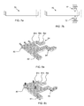
- Figure 7 illustrates schematically how guides are used to suppress out-of-plane vibrations.
- Figure 7a represents the unguided resonator 70: it is clamped on one side and free at the other end, giving a range of movement shown by dotted lines.
- the operated resonance mode is the longitudinal or length-extensional vibration. Out-of-plane vibrations are not suppressed.
- guides 72 are shown schematically.
- the longitudinal mode is the operated vibration and this movement is not hampered.
- the guides only restrict unwanted out-of-plane vibrations, and are designed to be (as far as possible) frictionless guides, which thus do not act on the desired mode of vibration, but completely restrict out-of-plane motion.
- the only construction material available is the substrate, typically a mono-crystalline slab of silicon, and it is desired to construct all device features in a single plane. This means it is not possible to attach physical bearings to the resonator (such as schematically shown in Figure 7b ).
- the designs of the invention provide well-matched bodies attached to the main resonator body, acting as frictionless guiders in only one direction.
- This "matched” feature refers to the resonance frequency, as explained below.
- Figures 8a and 8b show two simulated modes of vibration of a guided resonator of the invention.
- the longitudinal vibration in Figure 8a is the intended principal mode of operation.
- the design shown in Figure 8 comprises a main resonator mass 80 (like the mass 205 in Figure 2 ) and a length-extending member 82 (like the arms 20a or 20b in Figure 2 ).
- a main resonator mass 80 like the mass 205 in Figure 2
- a length-extending member 82 like the arms 20a or 20b in Figure 2
- These guide portions comprise arms 84 which extend at one end from the main resonator mass 80 to a fixed connection at the other end.
- the arms include portions that extend transversely of the principal direction of vibration, but in the same plane as the resonator mass.
- the arms have a "Z" shape, with a first portion 84a transverse to the vibration direction, a second portion 84b parallel to the vibration direction and a third portion 84c transverse to the vibration direction.
- the resonator and the connecting arms have the same exactly matched resonance frequency in the principal vibration direction. Furthermore, the external fixed connections at the ends of the connecting arms 84 are at nodal points for the principal vibration mode. In Figure 8b , a first out-of-plane bending mode of the system is shown. Since the frequency of this motion is not matched for resonator and connecting arms, there will be an acoustical impedance mismatch and energy will leak away to the surroundings. This motion is therefore heavily damped.
- the arms act as quarter wavelength-resonators, as known in acoustics. They do so, since their resonance frequency in the length-extensional direction of the resonator is perfectly matched to that of the resonator.
- Figure 9 shows possible resonator designs using the approach explained with reference to Figure 8 as applied to the resonator design of Figure 2 .
- Figure 9a shows the resonator of Figure 2 for reference.
- the anchor elements 23,24 are the points at which the resonator is fixed to the outside, and these are at nodal points, as a result of the symmetry of the resonator about a mirror axis perpendicular to the vibration direction (shown by arrows).
- Figure 9b shows a first example in accordance with the invention.
- Each resonator mass 205 is connected to an additional anchor point 90 by a straight arm 92 which extends perpendicularly to the vibration axis. These function as simple cantilevers attached in a symmetric way.
- Figure 9c shows a second example in accordance with the invention. This has two straight parallel arms 94a,94b extending in one direction transverse to the vibration axis from each resonator mass, and two more straight parallel arms 94a,94b extending in the opposite direction from each resonator mass.
- each arm 92 of the design of Figure 9b is split into two parallel arms, one at each end (along the vibration axis direction) of the resonator mass 205. This design suppresses more modes of vibration.
- Figure 9d modifies the arms 94a,94b of Figure 9c to provide Z-shaped arms 96 as shown in Figure 8 , and these allow for stress release.
- the desired resonance mode is the length-extensional mode and the parasitic modes have transversal vibration components.
- the application can be extended to any case where the undesired modes have non-zero vibration components in a direction where the desired mode has a zero vibration component.
- the desired mode is a z-directed bending mode, and the in-plane vibration can be suppressed.
- the invention is also not limited to the dob-bone shaped example given - the resonator may be as shown in Figure 1 . Furthermore, even when a length-extensional design is used, it may be fixed at one end and free at the other.
- the connecting arms are designed to have exactly the same resonant frequency as the resonator without arms.
- the resonant frequency of the connected resonator and arms should hence be the same.
- any frequency can be designed, so that the connecting arms do influence the resonant frequency of the resulting structure, but that resonant frequency has the desired value.
- the connecting arms need to be designed so that the quality factor of the resonator does not deteriorate.
- the resonator alone has a high Q factor, and the arms are designed in the manner of a quarter-wavelength attachment, in order to confine mechanical energy to within the resonator. The vibrational energy then reflects at the fixation of the arms, rather than transmitting energy to the outside world.
- the invention can be applied to any bulk-mode or length-extensional mode of operation.
- the invention is of particular interest for resonators that are thin with respect to width and length.
Landscapes
- Physics & Mathematics (AREA)
- Acoustics & Sound (AREA)
- Micromachines (AREA)
- Piezo-Electric Or Mechanical Vibrators, Or Delay Or Filter Circuits (AREA)
Abstract
A resonator (20a,205) in which in addition to the normal anchor (23) at a nodal point, a second anchor (90) arrangement is provided and an associated connecting arm (96) between the resonator body and the second anchor arrangement. The connecting arm connects to the resonator body at a non-nodal point so that it is not connected to a normal position where fixed connections are made. The connecting arm is used to suppress transverse modes of vibration.

Description
- This invention relates to resonators, for example MEMS resonators.
- In various products MEMS resonators are replacing quartz resonators as reference timing devices; they serve as reference resonators in oscillator circuits or as clocking reference to synchronise operations in digital circuitry. MEMS resonators offer the advantage of small dimensions (especially the small height is considered an advantage) with low-cost fabrication. In another application, MEMS resonators can also be combined to form a high-quality filter.
- In oscillator circuits, the most important demands on the MEMS resonator are:
- (i) a stable resonance frequency by having low phase noise and low jitter,
- (ii) a high quality factor, to minimise the contribution of the MEMS resonator to the phase noise of the oscillator, and
- (iii) a non-distorted large amplitude output signal to give a high signal-to-noise ratio of the oscillator and for a linear oscillator output. A high signal-to-noise ratio also enables the low phase noise and jitter to be achieved.
- If employed in a filter, MEMS resonators should meet the same demands for different reasons:
- (i) a stable resonance frequency to have stable filter operation
- (ii) a high quality factor to give a low insertion loss, and
- (iii) non-distorted large amplitude output signal, to give a large dynamic range.
- MEMS resonators exhibit a limit to the amplitude of the resonant oscillations which is below that which would be expected from the mechanical design. The origin of this limitation has only been fully understood very recently, and relates to the transfer of energy from the desired mode of vibration (eigenmode) to other eigenmodes.
- According to the invention, there is provided a resonator comprising a resonator body and actuation electrodes for driving the resonator into a resonant mode, in which the resonator body vibrates parallel to a first axis; and
a detection arrangement for detecting the vibration in the first axis direction and generating an electrical output signal derived from the vibration,
wherein the resonator comprises a first anchor arrangement at which the resonator is fixed in position, wherein the first anchor arrangement connects to the resonator body at a nodal point where no movement is induced by the vibration,
and wherein the resonator comprises a second anchor arrangement, and a connecting arm between the resonator body and the second anchor arrangement, wherein the connecting arm connects to the resonator body at a non-nodal point. - The invention enables the stable operation of the principal vibration mode (such as the length-extensional vibration mode) of a MEMS resonator to be extended. In previous designs, at a certain vibration level, this mode cannot be brought to vibrate more strongly. The cause is that parasitic out-of-plane modes are excited at this point. These parasitic modes have a transversal vibration component.
- The invention uses additional anchor points and connecting arms that are designed not to hamper the principal vibration mode, but which are designed to suppress or restrict all other vibrations.
- The connection arms can be thought of as guides in that they limit the movement in one direction but permit free movement along the principal vibration axis.
- For example, the connecting arm can have the same matched resonant frequency as the resonator mass for vibrations in the first axis direction, but a non-matched resonant frequency for vibrations in a transverse direction.
- The invention results in a structure in which the resonator is attached to the fixed external surroundings at more points than only the nodal (e.g. central) region.
- Preferably, the connecting arm extends from the resonator body in a direction transverse to the first axis direction.
- In one set of examples, the resonator body has two free ends and the first anchor arrangement connects to the resonator body centrally between the two free ends, and one or more connecting arms connect to each free end. This gives a symmetrical arrangement for known length-extensional resonators with two free ends.
- The resonator body can for example comprise a pair of expansion arms which extend along the first axis direction, with a head at each end of the pair of expansion arms, wherein the first anchor arrangement connects to the middle of the expansion arms and the connecting arm connects to the head. This is an arrangement of the invention applied to a so-called dog-bone resonator.
- A first connecting arm can extend outwardly in a first direction transverse to the first axis direction from one head, a second connecting arm extending outwardly in a second opposite direction transverse to the first axis direction from the one head, a third connecting arm extending outwardly in the first direction transverse to the first axis direction from the other head and a fourth connecting arm extending outwardly in the second opposite direction transverse to the first axis direction from the other head.
- This gives a structure that is symmetric about the first axis as well as symmetric about an axis perpendicular to the first axis direction (and therefore 180 degree rotationally symmetrical).
- There can be a first pair of connecting arms extending outwardly in a first direction transverse to the first axis direction from one head, a second pair of connecting arms extending outwardly in a second opposite direction transverse to the first axis direction from the one head, a third pair of connecting arms extending outwardly in the first direction transverse to the first axis direction from the other head and a fourth pair of connecting arms extending outwardly in the second opposite direction transverse to the first axis direction from the other head.
- The use of multiple connecting arms enables more parasitic modes to be suppressed.
- In all designs, the or each connecting arm can have a first portion transverse to the first axis direction, a second portion parallel to the first axis direction and a third portion transverse to the first axis direction. This Z shaped design reduces stresses induced in the resonator.
- The invention also provides a method of controlling a resonator which comprises a resonator body and actuation electrodes for driving the resonator into a resonant mode, in which the resonator body vibrates parallel to a first axis, the method comprising:
- fixing the resonator at a first anchor arrangement, wherein the first anchor arrangement connects to the resonator body at a nodal point where no movement is induced by the vibration,
- fixing the resonator at a second anchor arrangement, by connecting a connecting arm between the resonator body and the second anchor arrangement, wherein the connecting arm connects to the resonator body at a non-nodal point,
- wherein the method comprises using the connecting arm to suppress modes of vibration transverse to the first axis direction and avoiding damping of the main vibration mode in the fist axis direction by connecting the connecting arm to the second anchor arrangement at a nodal point of the vibrations of the combined resonator mass and connecting arm;
- detecting the vibration in the first axis direction; and
- generating an electrical output signal derived from the vibration.
- Examples of the invention will now be described with reference to the accompanying drawings, in which:
-
Figure 1 shows a known resonator; -
Figure 2 shows a modification to the resonator design ofFigure 1 ; -
Figure 3 shows the amplitude vs. frequency characteristics for the resonator ofFigure 2 ; -
Figure 4 shows how the amplitude vs. frequency characteristic can become clipped; -
Figure 5 shows how the clipping is related to parasitic vibration modes; -
Figure 6 shows the structure of resonator used to demonstrate how the invention can be implemented; -
Figure 7 shows in schematic form the aim of the design of the invention; -
Figure 8 shows one way to implement the connecting arm of the invention; and -
Figure 9 shows three different applications of the invention to the type of resonator ofFigure 6 . - MEMS resonators are designed such that an actuation signal excites one of the resonator's eigenmodes.
-
Figure 1 shows a resonator designed to vibrate in a length-extensional mode when an ac actuation voltage is applied. If properly designed, the actuation signal does not excite other modes (like bending modes or torsion modes in this example). - The design shown in
Figure 1 is a known piezoresistive MEMS resonator, which is described in more detail inWO 2004/053431 . - The
resonator 1 shown inFigure 1 comprises asubstrate 10 which is a silicon wafer. Alternatively, thesubstrate 10 may be a gallium arsenide wafer or it may comprise any other semiconducting, metal or dielectric material. Forresonators 1 designed for operation at frequencies above 10 MHz it is advantageous to use asubstrate 10 comprising a dielectric such as, e. g. glass, because this reduces the loss of electromagnetic energy dissipated in the substrate. - The
resonator 1 further comprises an electricallyconductive resonator element 20 having two parallel connectingelements substrate 10 viasupport elements anchor elements anchor elements substrate 10. Theresonator element 20 and thesupport elements substrate 10 except for the connection via theanchor elements - The
resonator element 20 has twoouter ends 205 in the longitudinal direction. These can be larger than the combined width of the connectingbeams Figure 2 . - Referring back to
Figure 1 , each of the outer ends 205 is faced by a respective electrode of the electricallyconductive actuator 30, and is spaced from the electrode by an actuation gap g. The actuators can be considered to be gate terminals, in that the control input is applied to these terminals. Theactuator 30 is able to receive an actuation potential difference VIN with respect to theresonator element 20 for elastically deforming theresonator element 20, using the electrostatic force. The actuation potential difference is a function of the input signal applied to theresonator 1. In addition to the input signal the actuation potential difference may typically further contain a DC component. The elastic deformation comprises a change of the length I by an amount dl shown inFig. 1 . - A feedback system controls the frequency of the actuation voltage, and the feedback loop stabilises at resonance with the actuation voltage frequency the same as the physical resonant frequency of the resonator.
- The
resonator element 20 is part of an oscillator circuit which is able to conduct an electrical current through theresonator element 20. Theresonator element 20 is electrically connected to the positive or negative pole of a DC voltage source VDC via anauxiliary resistor 27, theanchor element 24 and thesupport element 22. Theanchor 24 can be considered to be a drain terminal in that the DC voltage bias is applied to this terminal to drive a bias current through the device. Theresonator element 20 is further connected to ground via thesupport element 21 and theanchor element 23. Theanchor 23 can be considered to be a source terminal in that the bias current is collected at this terminal. Therefore, theresonator element 20 is able to conduct an electrical current I. It constitutes a resistor with an ohmic resistance R which causes a voltage drop V when theresonator element 20 conducts the electrical current I. - The
resonator element 20 constitutes a resistor with an ohmic resistance R which is a function of the change dl of the length I because theresonator element 20 comprises acentral part 19 with open space. Theresonator element 20 comprises the two mutuallyparallel beams respective support element elements 205. Thecentral part 19 has been created during a lithography step and etching step. It prevents the current from flowing from thesupport element 22 to thesupport element 21 in a straight line. The current has to follow the conductive path formed by theresonator element 20. This conductive path extends in the longitudinal direction. - The circuit is able to produce an output signal which is a function of the change dl of the length I and which is a function of the resistance R. To this end the circuit comprises a
measurement point 28 which is electrically connected to the circuit. It is situated between theauxiliary resistor 27 and theanchor element 24, and in operation it produces an electrical output signal which is the electrical potential difference Vout between themeasurement point 28 and thereference point 29 which is connected to ground. - In an alternative embodiment, not shown, the
auxiliary resistor 27 is not situated between the voltage source and theanchor element 24, but instead between theanchor element 23 and ground. In this case themeasurement point 28 is situated between theauxiliary resistor 27 and theanchor element 23. - In yet another embodiment, not shown either, the DC voltage source VDC and the
auxiliary resistor 27 are omitted. Theanchor element 24 is connected to the positive pole of a current source and theanchor element 23 is connected to the negative pole of the current source. Themeasurement point 28 is situated between the positive pole of the current source and theanchor element 24, and thereference point 29 is situated between theanchor element 23 and the negative pole of the current source. Thus, a voltage is measured for a constant current, or else a current portion is measured for a constant total voltage. - The output signal is again a function of the change dl of the length I as will be understood by those skilled in the art. Thus, sensing using current bias or voltage bias can be employed.
- The resulting mechanical resonance is in-plane of the drawing and is symmetrical. As mentioned above, the left and right parts of the resonator can be enlarged to define masses of relatively larger stiffness than the intermediate beams, so the compression and expansion that cause the resonator-vibration occurs in the beams.
- Since the mechanical vibration is symmetrical, the centre of the structure between the drain and
source - The so called actuation-gap on each side is located between the
gate electrodes 30 and the resonator mass and is in the order of a few hundred nm. - The resonator may be manufactured using a technique well known in the field of micro electromechanical systems (MEMS).
- A plot of the vibration amplitude versus the actuation frequency is shown in
Figure 3 . As shown, the resonator has a vibration amplitude which has a peak at a specific resonant frequency. - Ideally, the MEMS resonator is a purely linear device: if the actuation voltage doubles then the vibration amplitude doubles. Unfortunately, amplitude saturation is observed, meaning that the peak of the vibration amplitude peak is limited to a fixed level. This is shown in
Figure 4 , which shows the amplitude plots ofFigure 3 (vibration amplitude vs. actuation frequency) for different actuation voltages. The actuation level is expressed in dBm, providing a measure of signal power. - For the larger actuation voltages, the capping can be seen.
- This undesired saturation effect has been reported from groups all over the world and hinders successful use of MEMS resonators for oscillator and filter applications.
- The origin of this amplitude saturation has only very recently been revealed. If its vibration amplitude is above a particular threshold, the length-extensional vibration excites another eigenmode (or a combination of eigenmodes), which will be referred to as a parasitic mode.
- The parasitic mode drains energy from the desired length-extensional mode. An increase in actuation amplitude does not lead to an increased amplitude of the desired mode, but rather to an increase of amplitude of the parasitic mode. This effect is called autoparametric resonance and is discussed in C van der Avoort et al "Amplitude saturation of MEMS resonators explained by autoparametric resonance" 2010 J. Micromech. Microeng. 20 105012.
- This effect is shown in
Figure 5 , which shows actual measurements of saturation. The electrical output generated by the longitudinal vibration (plot 50) is saturated at a certain point. Optical vibration measurements of the out-of-plane vibration are shown asplot 52. These occur at the eigenfrequency for the out-of-plane mode, which is different from the driven longitudinal mode. This shows an increasing amplitude of this mode as the driving level is further increased. - Thus, the regular electrical response of the resonator is limited, and beyond a certain driving force level the electrical output signal does not grow anymore.
- When the principal mode is a length-extension mode, the parasitic modes involved are bending or torsion modes or combinations of them. In either of these modes there is a transversal (i.e. out-of-plane) vibration component.
- The energy drainage due to autoparametric resonance occurs even for relatively small length-extensional vibration amplitudes if the operation frequency of the resonator (i.e. the actuation frequency) exactly matches the eigenfrequency of the parasitic mode. Thus, under the circumstance that there is an exact frequency match, the MEMS resonator does not meet the demand of having a non-distorted large amplitude output signal.
- There are also usually a variety of parasitic modes with eigenfrequencies that lead to interaction in the vicinity of the operation frequency.
- A method is therefore desired to simultaneously suppress all unwanted out-of-plane modes.
- The invention provides a resonator in which in addition to the normal anchor at a nodal point, a second anchor arrangement is provided and an associated connecting arm between the resonator body and the second anchor arrangement. The connecting arm connects to the resonator body at a non-nodal point so that it is not connected to a normal position where fixed connections are made. The connecting arm connects to the second anchor arrangement at a nodal point of the vibrations of the combined resonator mass and connecting arm. This means that the second anchor can be considered as at a nodal point of the combination of the connecting arm and the resonator mass. They can together have the same resonant frequency as the resonator mass alone (without the connecting arm) so that the desired resonance is not damped.
- The invention is based on suppressing a transverse mode, e.g. a bending mode, so that the critical value can be shifted and the regular response of the principal vibration mode can achieve larger values. It is known that the suspension of a resonator at a nodal point of the vibration mode is favourable for the quality factor of the resonator, i.e. the resonator will show low damping or dissipative losses. The invention is based on altering the resonator structure, to maintain the desired requirement that in the desired mode of operation the resonator is attached to the outside world only at nodal (non-moving) points, but to suppress the other parasitic modes of operation.
- The invention in particular makes use of additional suspension (anchor) points on the resonator. These suspension points do not hamper the intended motion and therefore act as frictionless guiders of this motion. On the other hand, these same suspensions should limit/restrict any other motion of the resonator.
- With reference to
Figure 5 , the aim of the invention is to shift theplot 52 towards an increasing driving force (to the right), since the level of driving force at which energy is transferred to the parasitic mode determines when the vibration amplitude of the principal mode becomes capped. This is at a driving force of 0.05 (arbitrary units) inFigure 5 . By shiftingplot 52 to the right, more of the linear initial part ofplot 50 is effective before the capping takes place. -
Figure 6 is a scanning electron microscope micrograph of the type of resonator shown inFigure 2 . The structure is simulated numerically in order to find resonance modes and corresponding frequencies. -
Figure 7 illustrates schematically how guides are used to suppress out-of-plane vibrations.Figure 7a represents the unguided resonator 70: it is clamped on one side and free at the other end, giving a range of movement shown by dotted lines. The operated resonance mode is the longitudinal or length-extensional vibration. Out-of-plane vibrations are not suppressed. - In
Figure 7b guides 72 are shown schematically. The longitudinal mode is the operated vibration and this movement is not hampered. The guides only restrict unwanted out-of-plane vibrations, and are designed to be (as far as possible) frictionless guides, which thus do not act on the desired mode of vibration, but completely restrict out-of-plane motion. The only construction material available is the substrate, typically a mono-crystalline slab of silicon, and it is desired to construct all device features in a single plane. This means it is not possible to attach physical bearings to the resonator (such as schematically shown inFigure 7b ). - Instead, the designs of the invention provide well-matched bodies attached to the main resonator body, acting as frictionless guiders in only one direction. This "matched" feature refers to the resonance frequency, as explained below.
-
Figures 8a and 8b show two simulated modes of vibration of a guided resonator of the invention. The longitudinal vibration inFigure 8a is the intended principal mode of operation. - The design shown in
Figure 8 comprises a main resonator mass 80 (like the mass 205 inFigure 2 ) and a length-extending member 82 (like thearms Figure 2 ). In addition, there are two connectingarms 84 which function as guide portions which serve to suppress out-of-plane vibrations. These guide portions comprisearms 84 which extend at one end from themain resonator mass 80 to a fixed connection at the other end. The arms include portions that extend transversely of the principal direction of vibration, but in the same plane as the resonator mass. In the example shown, the arms have a "Z" shape, with afirst portion 84a transverse to the vibration direction, asecond portion 84b parallel to the vibration direction and athird portion 84c transverse to the vibration direction. - The resonator and the connecting arms have the same exactly matched resonance frequency in the principal vibration direction. Furthermore, the external fixed connections at the ends of the connecting
arms 84 are at nodal points for the principal vibration mode. InFigure 8b , a first out-of-plane bending mode of the system is shown. Since the frequency of this motion is not matched for resonator and connecting arms, there will be an acoustical impedance mismatch and energy will leak away to the surroundings. This motion is therefore heavily damped. - As mentioned before, attaching a vibrating structure at a nodal point is desired to minimise dissipative losses. In
Figure 8a the arms act as quarter wavelength-resonators, as known in acoustics. They do so, since their resonance frequency in the length-extensional direction of the resonator is perfectly matched to that of the resonator. - In
Figure 8b vibrational energy will leak away through the attached bodies, since the connection to the outside world is not made at a nodal point for that mode of vibration. -
Figure 9 shows possible resonator designs using the approach explained with reference toFigure 8 as applied to the resonator design ofFigure 2 . -
Figure 9a shows the resonator ofFigure 2 for reference. Theanchor elements -
Figure 9b shows a first example in accordance with the invention. - Each
resonator mass 205 is connected to anadditional anchor point 90 by astraight arm 92 which extends perpendicularly to the vibration axis. These function as simple cantilevers attached in a symmetric way. -
Figure 9c shows a second example in accordance with the invention. This has two straightparallel arms parallel arms arm 92 of the design ofFigure 9b is split into two parallel arms, one at each end (along the vibration axis direction) of theresonator mass 205. This design suppresses more modes of vibration. -
Figure 9d modifies thearms Figure 9c to provide Z-shapedarms 96 as shown inFigure 8 , and these allow for stress release. - These designs show that the two opposite free ends of the resonator can be guided by using 4 or 8 identical guiding structures, which can be simple straight cantilevers or more complicated structures. To avoid introducing stresses in the resonator they can have a "Z" (or "S" shape).
- These designs result in additional resonator suspensions (anchors).
- In the example above, the desired resonance mode is the length-extensional mode and the parasitic modes have transversal vibration components. In principle the application can be extended to any case where the undesired modes have non-zero vibration components in a direction where the desired mode has a zero vibration component. For example, if the desired mode is a z-directed bending mode, and the in-plane vibration can be suppressed.
- The invention is also not limited to the dob-bone shaped example given - the resonator may be as shown in
Figure 1 . Furthermore, even when a length-extensional design is used, it may be fixed at one end and free at the other. - In the examples explained above, the connecting arms are designed to have exactly the same resonant frequency as the resonator without arms. In principle, the resonant frequency of the connected resonator and arms should hence be the same.
- However, any frequency can be designed, so that the connecting arms do influence the resonant frequency of the resulting structure, but that resonant frequency has the desired value. The connecting arms need to be designed so that the quality factor of the resonator does not deteriorate. In the examples above, the resonator alone has a high Q factor, and the arms are designed in the manner of a quarter-wavelength attachment, in order to confine mechanical energy to within the resonator. The vibrational energy then reflects at the fixation of the arms, rather than transmitting energy to the outside world.
- The invention can be applied to any bulk-mode or length-extensional mode of operation. The invention is of particular interest for resonators that are thin with respect to width and length.
- Other variations to the disclosed embodiments can be understood and effected by those skilled in the art in practicing the claimed invention, from a study of the drawings, the disclosure, and the appended claims. In the claims, the word "comprising" does not exclude other elements or steps, and the indefinite article "a" or "an" does not exclude a plurality. The mere fact that certain measures are recited in mutually different dependent claims does not indicate that a combination of these measured cannot be used to advantage. Any reference signs in the claims should not be construed as limiting the scope.
Claims (9)
- A resonator (1) comprising a resonator body and actuation electrodes (30) for driving the resonator into a resonant mode, in which the resonator body vibrates parallel to a first axis; and
a detection arrangement (27,28,29) for detecting the vibration in the first axis direction and generating an electrical output signal derived from the vibration,
wherein the resonator comprises a first anchor arrangement (23,24) at which the resonator is fixed in position, wherein the first anchor arrangement connects to the resonator body at a nodal point where no movement is induced by the vibration,
and wherein the resonator comprises a second anchor arrangement (90), and a connecting arm (92;94a,94b;96) between the resonator body (205) and the second anchor arrangement, wherein the connecting arm connects to the resonator body at a non-nodal point. - A resonator as claimed in claim 1, wherein the connecting arm (92;94a,94b;96) extends from the resonator body in a direction transverse to the first axis direction.
- A resonator as claimed in claim 2, wherein the connecting arm (92;94a,94b;96) has the same resonant frequency as the resonator mass for vibrations in the first axis direction, but a non-matched resonant frequency for vibrations in a transverse direction.
- A resonator as claimed in preceding claim, where the resonator body has two free ends and the first anchor arrangement connects to the resonator body centrally between the two free ends, and wherein one or more connecting arms (92;94a,94b;96) connect to each free end.
- A resonator as claimed in any preceding claim, wherein the resonator body comprises a pair of expansion arms (20a,20b) which extend along the first axis direction, with a head (205) at each end of the pair of expansion arms, wherein the first anchor arrangement connects to the middle of the expansion arms and the connecting arm (92;94a,94b;96) connects to the head (205).
- A resonator as claimed in claim 5, comprising a first connecting arm (92;94a,94b;96) extending outwardly in a first direction transverse to the first axis direction from one head (205), a second connecting arm (92;94a,94b;96) extending outwardly in a second opposite direction transverse to the first axis direction from the one head, a third connecting arm (92;94a,94b;96) extending outwardly in the first direction transverse to the first axis direction from the other head and a fourth connecting arm (92;94a,94b;96) extending outwardly in the second opposite direction transverse to the first axis direction from the other head.
- A resonator as claimed in claim 5, comprising a first pair of connecting arms (94a,94b) extending outwardly in a first direction transverse to the first axis direction from one head (205), a second pair of connecting arms (94a,94b) extending outwardly in a second opposite direction transverse to the first axis direction from the one head, a third pair of connecting arms (94a,94b) extending outwardly in the first direction transverse to the first axis direction from the other head and a fourth pair of connecting arms (94a,94b) extending outwardly in the second opposite direction transverse to the first axis direction from the other head.
- A resonator as claimed in any preceding claim, wherein the or each connecting arm (92; 94a,94b; 96) has a first portion (84a) transverse to the first axis direction, a second portion (84b) parallel to the first axis direction and a third portion (84c) transverse to the first axis direction.
- A method of controlling a resonator (1) which comprises a resonator body and actuation electrodes (30) for driving the resonator into a resonant mode, in which the resonator body vibrates parallel to a first axis the method comprising:fixing the resonator at a first anchor arrangement (23,24), wherein the first anchor arrangement connects to the resonator body at a nodal point where no movement is induced by the vibration,fixing the resonator at a second anchor arrangement (90), by connecting a connecting arm (92;94a,94b;96) between the resonator body (205) and the second anchor arrangement, wherein the connecting arm connects to the resonator body at a non-nodal point,wherein the method comprises using the connecting arm to suppress modes of vibration transverse to the first axis direction and avoiding damping of the main vibration mode in the fist axis direction by connecting the connecting arm to the second anchor arrangement at a nodal point of the vibrations of the combined resonator mass and connecting arm;detecting the vibration in the first axis direction; andgenerating an electrical output signal derived from the vibration.
Priority Applications (3)
| Application Number | Priority Date | Filing Date | Title |
|---|---|---|---|
| EP11162888A EP2515436A1 (en) | 2011-04-18 | 2011-04-18 | MEMS resonator and method of controlling the same |
| US13/446,894 US8854150B2 (en) | 2011-04-18 | 2012-04-13 | Resonator and method of controlling the same |
| CN201210109245.9A CN102751961B (en) | 2011-04-18 | 2012-04-13 | Resonator and method of controlling the same |
Applications Claiming Priority (1)
| Application Number | Priority Date | Filing Date | Title |
|---|---|---|---|
| EP11162888A EP2515436A1 (en) | 2011-04-18 | 2011-04-18 | MEMS resonator and method of controlling the same |
Publications (1)
| Publication Number | Publication Date |
|---|---|
| EP2515436A1 true EP2515436A1 (en) | 2012-10-24 |
Family
ID=44544157
Family Applications (1)
| Application Number | Title | Priority Date | Filing Date |
|---|---|---|---|
| EP11162888A Withdrawn EP2515436A1 (en) | 2011-04-18 | 2011-04-18 | MEMS resonator and method of controlling the same |
Country Status (3)
| Country | Link |
|---|---|
| US (1) | US8854150B2 (en) |
| EP (1) | EP2515436A1 (en) |
| CN (1) | CN102751961B (en) |
Cited By (5)
| Publication number | Priority date | Publication date | Assignee | Title |
|---|---|---|---|---|
| WO2016064678A1 (en) * | 2014-10-22 | 2016-04-28 | Micrel, Inc. | Compound spring mems resonator for oscillators and real-time clock applications |
| US9866200B2 (en) | 2014-10-22 | 2018-01-09 | Microchip Technology Incorporated | Multiple coil spring MEMS resonator |
| WO2019155119A1 (en) | 2018-02-08 | 2019-08-15 | Tikitin Oy | Coupled mems resonator |
| WO2019155120A1 (en) * | 2018-02-08 | 2019-08-15 | Tikitin Oy | Mems resonator array arrangement |
| US11799441B2 (en) | 2019-04-12 | 2023-10-24 | Kyocera Tikitin Oy | MEMS resonator |
Families Citing this family (5)
| Publication number | Priority date | Publication date | Assignee | Title |
|---|---|---|---|---|
| EP2713509B1 (en) * | 2012-09-27 | 2015-03-25 | Nxp B.V. | MEMS resonator with improved amplitude saturation |
| US9954513B1 (en) | 2012-12-21 | 2018-04-24 | Analog Devices, Inc. | Methods and apparatus for anchoring resonators |
| US9634227B1 (en) * | 2013-03-06 | 2017-04-25 | Analog Devices, Inc. | Suppression of spurious modes of vibration for resonators and related apparatus and methods |
| CN104779122A (en) * | 2015-03-27 | 2015-07-15 | 苏州锟恩电子科技有限公司 | Silicon beam structure of RF MEMS (radio frequency microelectromechanical system) switch |
| CN111181490B (en) * | 2020-01-02 | 2022-02-11 | 西安交通大学 | Silicon micro-resonance frequency multiplier based on super-resonance synchronization technology |
Citations (7)
| Publication number | Priority date | Publication date | Assignee | Title |
|---|---|---|---|---|
| WO2004053431A2 (en) | 2002-12-10 | 2004-06-24 | Koninklijke Philips Electronics N.V. | Transducer and electronic device |
| US20090153267A1 (en) * | 2007-12-18 | 2009-06-18 | Markus Lutz | MEMS resonator structure and method |
| WO2010035184A1 (en) * | 2008-09-23 | 2010-04-01 | Nxp B.V. | Device with a micro electromechanical structure |
| US20100181868A1 (en) * | 2008-12-17 | 2010-07-22 | Sand9, Inc. | Multi-port mechanical resonating devices and related methods |
| FR2946479A1 (en) * | 2009-06-09 | 2010-12-10 | Commissariat Energie Atomique | ELECTROMECHANICAL RESONATOR WITH RESONANT ANCHORING. |
| US20100314969A1 (en) * | 2009-03-26 | 2010-12-16 | Sand9, Inc. | Mechanical resonating structures and methods |
| US20110025426A1 (en) * | 2009-08-03 | 2011-02-03 | Nxp B.V. | Frequency selection and amplifying device |
Family Cites Families (17)
| Publication number | Priority date | Publication date | Assignee | Title |
|---|---|---|---|---|
| US3490056A (en) * | 1967-05-16 | 1970-01-13 | Gen Electric | Electromechanical resonator for integrated circuits |
| US3602842A (en) * | 1969-08-08 | 1971-08-31 | Scudder Smith | Electromechanical oscillator including a dual vibrator for producing a bent frequency |
| AU5869994A (en) * | 1992-12-11 | 1994-07-04 | Regents Of The University Of California, The | Microelectromechanical signal processors |
| US5491604A (en) * | 1992-12-11 | 1996-02-13 | The Regents Of The University Of California | Q-controlled microresonators and tunable electronic filters using such resonators |
| US5998911A (en) * | 1996-11-26 | 1999-12-07 | Ngk Insulators, Ltd. | Vibrator, vibratory gyroscope, and vibration adjusting method |
| JP3973742B2 (en) * | 1997-07-04 | 2007-09-12 | 日本碍子株式会社 | Vibrating gyroscope |
| US6424074B2 (en) * | 1999-01-14 | 2002-07-23 | The Regents Of The University Of Michigan | Method and apparatus for upconverting and filtering an information signal utilizing a vibrating micromechanical device |
| US6624726B2 (en) * | 2001-08-31 | 2003-09-23 | Motorola, Inc. | High Q factor MEMS resonators |
| DE10152254A1 (en) * | 2001-10-20 | 2003-04-30 | Bosch Gmbh Robert | Micromechanical component and corresponding manufacturing method |
| US8013493B2 (en) | 2007-06-01 | 2011-09-06 | Nxp B.V. | MEMS resonators |
| ATE513362T1 (en) * | 2007-11-19 | 2011-07-15 | Nxp Bv | RESONATOR |
| JP4690436B2 (en) * | 2008-05-01 | 2011-06-01 | 株式会社半導体理工学研究センター | MEMS resonator, MEMS oscillation circuit, and MEMS device |
| EP2291910B1 (en) * | 2008-06-18 | 2011-11-09 | Nxp B.V. | Mems resonator for filtering and mixing |
| US8143971B2 (en) | 2008-07-11 | 2012-03-27 | Taiwan Semiconductor Manufacturing Company, Ltd. | MEMS resonator |
| EP2239845A1 (en) | 2009-04-09 | 2010-10-13 | Nxp B.V. | MEMS resonator |
| EP2302792B1 (en) | 2009-09-22 | 2012-11-14 | Nxp B.V. | Resonator |
| US8497747B1 (en) * | 2011-03-02 | 2013-07-30 | Sandia Corporation | Microelectromechanical filter formed from parallel-connected lattice networks of contour-mode resonators |
-
2011
- 2011-04-18 EP EP11162888A patent/EP2515436A1/en not_active Withdrawn
-
2012
- 2012-04-13 US US13/446,894 patent/US8854150B2/en active Active
- 2012-04-13 CN CN201210109245.9A patent/CN102751961B/en not_active Expired - Fee Related
Patent Citations (7)
| Publication number | Priority date | Publication date | Assignee | Title |
|---|---|---|---|---|
| WO2004053431A2 (en) | 2002-12-10 | 2004-06-24 | Koninklijke Philips Electronics N.V. | Transducer and electronic device |
| US20090153267A1 (en) * | 2007-12-18 | 2009-06-18 | Markus Lutz | MEMS resonator structure and method |
| WO2010035184A1 (en) * | 2008-09-23 | 2010-04-01 | Nxp B.V. | Device with a micro electromechanical structure |
| US20100181868A1 (en) * | 2008-12-17 | 2010-07-22 | Sand9, Inc. | Multi-port mechanical resonating devices and related methods |
| US20100314969A1 (en) * | 2009-03-26 | 2010-12-16 | Sand9, Inc. | Mechanical resonating structures and methods |
| FR2946479A1 (en) * | 2009-06-09 | 2010-12-10 | Commissariat Energie Atomique | ELECTROMECHANICAL RESONATOR WITH RESONANT ANCHORING. |
| US20110025426A1 (en) * | 2009-08-03 | 2011-02-03 | Nxp B.V. | Frequency selection and amplifying device |
Non-Patent Citations (3)
| Title |
|---|
| BONTEMPS J J M ET AL: "56 MHZ piezoresistive micromechanical oscillator", SOLID-STATE SENSORS, ACTUATORS AND MICROSYSTEMS CONFERENCE, June 2009 (2009-06-01), pages 1433 - 1436, XP031545723 * |
| C VAN DER AVOORT ET AL.: "Amplitude saturation of MEMS resonators explained by autoparametric resonance", J. MICROMECH. MICROENG., vol. 20, 2010, pages 105012 |
| YUAN XIE ET AL: "Spurious mode suppression in UHF micromechanical extensional wine-glass ring resonators", IEEE MICRO ELECTRO MECHANICAL SYSTEMS CONFERENCE, January 2005 (2005-01-01), pages 219 - 222, XP010811698 * |
Cited By (16)
| Publication number | Priority date | Publication date | Assignee | Title |
|---|---|---|---|---|
| CN107251426B (en) * | 2014-10-22 | 2021-02-09 | 微芯片科技公司 | Composite spring MEMS resonator for frequency and timing generation |
| TWI581471B (en) * | 2014-10-22 | 2017-05-01 | 麥奎爾股份有限公司 | Compound spring mems resonators for frequency and timing generation |
| CN107251426A (en) * | 2014-10-22 | 2017-10-13 | 微芯片科技公司 | The complex spring MEMS resonator generated for frequency and timing |
| US9866200B2 (en) | 2014-10-22 | 2018-01-09 | Microchip Technology Incorporated | Multiple coil spring MEMS resonator |
| US9923545B2 (en) | 2014-10-22 | 2018-03-20 | Microchip Technology Incorporated | Compound spring MEMS resonators for frequency and timing generation |
| WO2016064678A1 (en) * | 2014-10-22 | 2016-04-28 | Micrel, Inc. | Compound spring mems resonator for oscillators and real-time clock applications |
| US11196402B2 (en) | 2018-02-08 | 2021-12-07 | Kyocera Tikitin Oy | Coupled MEMS resonator |
| WO2019155120A1 (en) * | 2018-02-08 | 2019-08-15 | Tikitin Oy | Mems resonator array arrangement |
| WO2019155119A1 (en) | 2018-02-08 | 2019-08-15 | Tikitin Oy | Coupled mems resonator |
| CN111727562A (en) * | 2018-02-08 | 2020-09-29 | 京瓷帝基廷公司 | Coupled MEMS Resonators |
| US11736087B2 (en) | 2018-02-08 | 2023-08-22 | Kyocera Tikitin Oy | Coupled MEMS resonator |
| JP2023182831A (en) * | 2018-02-08 | 2023-12-26 | キョーセラ ティキティン オーユー | Coupled MEMS resonator |
| US12132467B2 (en) | 2018-02-08 | 2024-10-29 | Kyocera Technologies Oy | MEMS resonator array arrangement |
| JP7629070B2 (en) | 2018-02-08 | 2025-02-12 | キョーセラ テクノロジーズ オーユー | Coupled MEMS resonator |
| CN111727562B (en) * | 2018-02-08 | 2025-04-18 | 京瓷技术公司 | Coupled MEMS Resonators |
| US11799441B2 (en) | 2019-04-12 | 2023-10-24 | Kyocera Tikitin Oy | MEMS resonator |
Also Published As
| Publication number | Publication date |
|---|---|
| US20120262242A1 (en) | 2012-10-18 |
| CN102751961A (en) | 2012-10-24 |
| CN102751961B (en) | 2015-06-10 |
| US8854150B2 (en) | 2014-10-07 |
Similar Documents
| Publication | Publication Date | Title |
|---|---|---|
| US8854150B2 (en) | Resonator and method of controlling the same | |
| US6624726B2 (en) | High Q factor MEMS resonators | |
| JP4589920B2 (en) | Temperature compensation for silicon MEMS resonators | |
| JP5446187B2 (en) | Vibrating piece and vibration type sensor | |
| JP2008209389A (en) | Acceleration sensor | |
| Mallick et al. | Multi-frequency MEMS electromagnetic energy harvesting | |
| CN107147370B (en) | A MEMS oscillator based on vibration mode coupling and its control method | |
| KR101534351B1 (en) | MEMS DEVICE AND METHOD | |
| US9252707B2 (en) | MEMS mass bias to track changes in bias conditions and reduce effects of flicker noise | |
| EP2409403A1 (en) | Resonator device and method of optimizing a q-factor | |
| KR101738869B1 (en) | Improved micromechanical resonator | |
| CN102710231B (en) | Resonator and Method of Controlling the Same | |
| CN107635909B (en) | Micromechanical spring device and method for producing a micromechanical spring device | |
| JPH08278142A (en) | Angular velocity sensor | |
| US8373513B2 (en) | Compensated micro/nano-resonator with improved capacitive detection and method for producing same | |
| US9318997B2 (en) | Resonator | |
| JP5081586B2 (en) | Micromechanical resonator | |
| JP4965962B2 (en) | Micromechanical resonator | |
| US8624137B2 (en) | Device with a micro electromechanical structure | |
| JP2009080069A (en) | Acceleration sensor, load sensor | |
| KR101850117B1 (en) | Anti-resonant vibration isolation and vibration energy harvesting device | |
| Liang et al. | Realization of quartz MEMS accelerometer based on flip chip process | |
| CN117833854A (en) | MEMS Resonators | |
| Lee et al. | Exploring parametric resonance effects in bulk-mode CMOS-MEMS resonators |
Legal Events
| Date | Code | Title | Description |
|---|---|---|---|
| PUAI | Public reference made under article 153(3) epc to a published international application that has entered the european phase |
Free format text: ORIGINAL CODE: 0009012 |
|
| AK | Designated contracting states |
Kind code of ref document: A1 Designated state(s): AL AT BE BG CH CY CZ DE DK EE ES FI FR GB GR HR HU IE IS IT LI LT LU LV MC MK MT NL NO PL PT RO RS SE SI SK SM TR |
|
| AX | Request for extension of the european patent |
Extension state: BA ME |
|
| 17P | Request for examination filed |
Effective date: 20130424 |
|
| 17Q | First examination report despatched |
Effective date: 20130529 |
|
| STAA | Information on the status of an ep patent application or granted ep patent |
Free format text: STATUS: THE APPLICATION IS DEEMED TO BE WITHDRAWN |
|
| 18D | Application deemed to be withdrawn |
Effective date: 20131009 |