EP2515385A1 - Connector - Google Patents
Connector Download PDFInfo
- Publication number
- EP2515385A1 EP2515385A1 EP12002308A EP12002308A EP2515385A1 EP 2515385 A1 EP2515385 A1 EP 2515385A1 EP 12002308 A EP12002308 A EP 12002308A EP 12002308 A EP12002308 A EP 12002308A EP 2515385 A1 EP2515385 A1 EP 2515385A1
- Authority
- EP
- European Patent Office
- Prior art keywords
- signal terminals
- terminals
- ground
- ground terminal
- signal
- Prior art date
- Legal status (The legal status is an assumption and is not a legal conclusion. Google has not performed a legal analysis and makes no representation as to the accuracy of the status listed.)
- Withdrawn
Links
- 238000009413 insulation Methods 0.000 claims description 2
- 230000005540 biological transmission Effects 0.000 description 10
- 239000002184 metal Substances 0.000 description 9
- 230000004048 modification Effects 0.000 description 9
- 238000012986 modification Methods 0.000 description 9
- 230000005684 electric field Effects 0.000 description 5
- 239000004020 conductor Substances 0.000 description 3
- 238000004519 manufacturing process Methods 0.000 description 3
- 239000000470 constituent Substances 0.000 description 2
- 239000011347 resin Substances 0.000 description 2
- 229920005989 resin Polymers 0.000 description 2
- 210000004899 c-terminal region Anatomy 0.000 description 1
- 238000001746 injection moulding Methods 0.000 description 1
- 239000000463 material Substances 0.000 description 1
- 238000000465 moulding Methods 0.000 description 1
- 230000002093 peripheral effect Effects 0.000 description 1
- 238000005476 soldering Methods 0.000 description 1
Images




Classifications
-
- H—ELECTRICITY
- H01—ELECTRIC ELEMENTS
- H01R—ELECTRICALLY-CONDUCTIVE CONNECTIONS; STRUCTURAL ASSOCIATIONS OF A PLURALITY OF MUTUALLY-INSULATED ELECTRICAL CONNECTING ELEMENTS; COUPLING DEVICES; CURRENT COLLECTORS
- H01R13/00—Details of coupling devices of the kinds covered by groups H01R12/70 or H01R24/00 - H01R33/00
- H01R13/646—Details of coupling devices of the kinds covered by groups H01R12/70 or H01R24/00 - H01R33/00 specially adapted for high-frequency, e.g. structures providing an impedance match or phase match
- H01R13/6461—Means for preventing cross-talk
- H01R13/6471—Means for preventing cross-talk by special arrangement of ground and signal conductors, e.g. GSGS [Ground-Signal-Ground-Signal]
-
- H—ELECTRICITY
- H01—ELECTRIC ELEMENTS
- H01R—ELECTRICALLY-CONDUCTIVE CONNECTIONS; STRUCTURAL ASSOCIATIONS OF A PLURALITY OF MUTUALLY-INSULATED ELECTRICAL CONNECTING ELEMENTS; COUPLING DEVICES; CURRENT COLLECTORS
- H01R24/00—Two-part coupling devices, or either of their cooperating parts, characterised by their overall structure
- H01R24/60—Contacts spaced along planar side wall transverse to longitudinal axis of engagement
- H01R24/62—Sliding engagements with one side only, e.g. modular jack coupling devices
- H01R24/64—Sliding engagements with one side only, e.g. modular jack coupling devices for high frequency, e.g. RJ 45
-
- H—ELECTRICITY
- H01—ELECTRIC ELEMENTS
- H01R—ELECTRICALLY-CONDUCTIVE CONNECTIONS; STRUCTURAL ASSOCIATIONS OF A PLURALITY OF MUTUALLY-INSULATED ELECTRICAL CONNECTING ELEMENTS; COUPLING DEVICES; CURRENT COLLECTORS
- H01R2107/00—Four or more poles
Definitions
- the present invention relates to a connector including signal terminals and a ground terminal.
- the terminals include signal terminals and ground terminals. In each of the rows, the signal terminals and the ground terminals are arrayed alternately. It is also known that crosstalk of high-frequency signals transmitted to the signal terminals may be reduced by setting a dimension in an array direction of each ground terminal as equal to or larger than twice that of each signal terminal (see Fig. 3 of H07-161414).
- the array direction herein refers to an array direction of the terminals in each row.
- an embodiment of the invention is devised to provide a connector that can suppress crosstalk and has a reduced dimension in an array direction of terminals.
- a connector of the present invention includes a body having insulation properties and a terminal group.
- the terminal group includes a plurality of signal terminals and a ground terminal.
- the signal terminals and the ground terminal are arrayed in a row along a first direction in the body.
- the signal terminals extend in a second direction orthogonal to the first direction.
- the ground terminal extends in the second direction and is disposed between two adjacent ones of the signal terminals.
- a widthwise dimension in the first direction of the ground terminal is less than twice that of each of the signal terminals.
- a thicknesswise dimension of at least a part of the ground terminal in a third direction orthogonal to the first and second directions is larger than that of each of the signal terminals.
- the ground terminal has a widthwise dimension in the first direction less than twice that of each signal terminal, while at least a part of the ground terminal has a thicknesswise dimension in the third direction larger than that of each signal terminal, which configuration can decrease a conductor resistance and a ground potential of the ground terminal. Consequently, the ground terminal of the second connector can suppress crosstalk between signals transmitted by the signal terminals, and it is possible to reduce the widthwise dimension in the first direction of the second connector.
- the ground terminal may include a plurality of ground terminals arranged in spaced relation to each other along the first direction.
- the signal terminals may be each interposed between adjacent two of the ground terminals.
- the ground terminals function as shield walls against electric field leakage from the signal terminals, thus improving electromagnetic interference (EMI) characteristics of the second connector.
- EMI electromagnetic interference
- the ground terminals exist on opposite sides of each signal terminal, which arrangement contributes to matched impedances between all the signal terminals.
- a center of a cross-section in the third direction of said part of the ground terminal may be located substantially at the same height in the third direction as centers of cross-sections in the third direction of portions of the signal terminals corresponding to said part of the ground terminal.
- the widthwise dimension in the first direction of the ground terminal may be smaller than that of each of the signal terminals. According to this aspect of the invention, the ground terminal having a smaller widthwise dimension than at least one of the signal terminals contributes to the reduction in the widthwise dimension in the first direction of the second connector.
- the ground terminal may have a generally identical outer shape, except the thicknesswise dimension thereof, to that of each of the signal terminals. According to this aspect of the invention, the ground terminal and the signal terminals can be created by pressing electrically conductive plates with different thicknesses using the same die, thus reducing the manufacturing cost of the second connector.
- the signal terminals may be electrically conductive plates extending not only in the second direction but also in the first direction.
- the ground terminal may be an electrically conductive plate extending not only in the second direction but also in the third direction.
- the signal terminals are electrically conductive plates extending in the first and second directions, while the ground terminal is an electrically conductive plate extending in the second and third directions, so that the ground terminal may function as a high shield wall against electric field leakage from the signal terminals.
- the second connector has improved EMI characteristics.
- the thicknesswise dimension in the third direction of at least said part of the ground terminal be equal to 1.5 times or larger than 1.5 times (i.e. is at least 1.5 times) that of each of the signal terminals.
- the terminal group may include a pair of first signal terminals and a second signal terminal.
- the pair of first signal terminals extends in the second direction orthogonal to the first direction and the first signal terminals are adjacent to each other in the first direction.
- the second signal terminal extends in the second direction.
- the ground terminal is disposed between one of the first signal terminals and the second signal terminal.
- the widthwise dimension in the first direction of the ground terminal is less than twice that of each of the first signal terminals.
- the thicknesswise dimension in the third direction of at least said part of the ground terminal is larger than that of each of the first and second signal terminals.
- the ground terminal has a widthwise dimension in the first direction less than twice that of each of the first signal terminals, while at least a part of the ground terminal has a thicknesswise dimension in the third direction larger than that of each of the first and second signal terminals, which configuration can decrease a conductor resistance and a ground potential of the ground terminal. Consequently, the ground terminal of the first connector can suppress crosstalk between signals transmitted by the first signal terminals and signals transmitted by the second signal terminal, and it is possible to reduce the widthwise dimension in the first direction of the first connector.
- the second terminal of the terminal group may comprise a pair of second signal terminals adjacent to each other in the first direction.
- the ground terminal may be disposed between the one first signal terminal and one of the second signal terminals.
- the ground terminal may comprise a plurality of ground terminals arranged in spaced relation to each other along the first direction.
- the pair of first signal terminals may be interposed between adjacent two of the ground terminals.
- the pair of second signal terminals may be interposed between another adjacent two of the ground terminals.
- the ground terminals function as shield walls against electric field leakage from the first and second signal terminals, improving electromagnetic interference (EMI) characteristics of the first connector.
- EMI electromagnetic interference
- this arrangement of the ground terminals contributes to matched impedances between the pair of first signal terminals and between the pair of second signal terminals.
- this aspect of the invention can improve transmission characteristics of the first and second signal terminals.
- a center of a cross-section in the third direction of said part of the ground terminal be located substantially at the same height in the third direction as centers of cross-sections in the third direction of portions of the first and second signal terminals corresponding to said part of the ground terminal.
- the widthwise dimension in the first direction of the ground terminal may be smaller than the widthwise dimension in the first direction of at least one of the first and second signal terminals. According to this aspect of the invention, the ground terminal having a smaller widthwise dimension than at least one of the first and second signal terminals contributes to the reduction in the widthwise dimension in the first direction of the first connector.
- the ground terminal may have a generally identical outer shape, except its thicknesswise dimension, to that of at least one of the first and second signal terminals.
- the ground terminal and at least one of the first and second signal terminals can be created by pressing electrically conductive plates with different thicknesses with the same die, thus reducing the manufacturing cost of the first connector.
- the first and second signal terminals may be electrically conductive plates extending not only in the second direction but also in the first direction.
- the ground terminal may be an electrically conductive plate extending not only in the second direction but also in the third direction.
- the first and second signal terminals are electrically conductive plates extending in the first and second directions, while the ground terminal is an electrically conductive plate extending in the second and third directions, so that the ground terminal may function as a high shield wall against electric field leakage from the first and second signal terminals.
- the first connector has improved EMI characteristics.
- the thicknesswise dimension in the third direction of at least said part of the ground terminal may be equal to or larger than 1.5 times that of each of the first and second signal terminals.
- FIG. 1 A connector according to an embodiment of the present invention will be described below referring to Figs. 1 to 4 .
- the connector shown in Fig. 1 is a receptacle connector mountable on a circuit board (not shown) and connectable with a plug connector (not shown).
- the connector includes a body 100, a shell 200, and a terminal group C. Respective components of the connector will be described in detail below. It should be noted that Figs.
- X direction is a first direction, which is a widthwise direction of the connector and an array direction of the terminal group C
- the Y direction is a second direction, which is a front-back direction of the connector and is orthogonal to the first direction X
- the Z direction is a third direction, which is a top-bottom direction of the connector and is orthogonal to the first and second directions X and Y
- the body 100 of rectangular parallelepiped shape is made of insulating resin.
- the body 100 has a main body 110 and a projection 120, as shown in Figs. 1 and 2 .
- the front surface in the second direction Y of the main body 110 has a substantially rectangular reception hole 111 for removably receiving a plug connector.
- the projection 120 extends from a back-side surface in the second direction Y of the reception hole 111.
- the projection 120 is a rectangular plate extending in the first direction X and the second direction Y.
- An upper surface of the projection 120 is formed with a plurality of grooves 121 extending in the second direction Y.
- the shell 200 is a rectangular tube made of an electrically conductive metal plate, covering the outer peripheral surface of the body 100, as shown in Fig. 1 and Figs. 2A, 2B .
- the terminal group C includes a pair of first signal terminals 310S, a pair of second signal terminals 320S, and a plurality of ground terminals 330G, as shown in Figs. 1 to 4 .
- the first and second signal terminals and the ground terminals are arrayed in a row along the first direction X inside the body 100 in an order of 330G, 310S, 310S, 330G, 320S, 320S, and 330G (i.e., the terminal group C is arrayed in a row along the first direction X inside the body 100).
- the pair of first signal terminals 310S are next to each other in the first direction X to form a differential pair for transmission of high-speed differential signals of 1 GHz or higher.
- the first signal terminals 310S are electrically conductive metal plates extending in the second direction Y.
- Each of the first signal terminals 310S has an intermediate portion 311 S, a contact portion 312S, a bent portion 313S, and a tail portion 314S.
- the intermediate portion 311S is a plate extending in the second direction Y, and it is embedded in and held by the main body 110 of the body 100.
- the intermediate portion 311S has a first end and a second end in the second direction Y, and the contact portion 312S is provided continuously to the first end and the bent portion 313S is provided continuously to the second end.
- the contact portion 312S is a plate extending in the second direction Y continuously to the intermediate portion 311 S.
- the contact portion 312S is received in each of the grooves 121 of the projection 120 of the body 100.
- the contact portion 312S has a curved portion of a circular arc shape that is curved upwardly in the third direction Z. The curved portion is contactable with a signal contact of the above-mentioned plug connector.
- the bent portion 3135 is a substantially L-shaped plate bent at a right angle to the intermediate portion 311S, and it extends in the third direction Z along a rear surface in the second direction Y of the main body 110.
- the tail portion 314S is a plate provided continuously to a lower end in the third direction Z of the bent portion 313S and bent at a right angle to the bent portion 313S to extend in the second direction Y.
- the tail portion 314S is connectable to a signal line of the circuit board.
- the pair of second signal terminals 320S are next to each other in the first direction X to form a differential pair for transmission of high-speed differential signals of I GHz or higher.
- the second signal terminals 320S are electrically conductive metal plates extending in the second direction Y, and they have the same configuration as the first signal terminals 310S.
- the second signal terminals 320S each have an intermediate portion 321 S, a contact portion 322S, a bent portion 323S, and a tail portion 324S. The respective portions of the second signal terminal 320S will not be described further in detail to avoid redundancy with the description of the first signal terminal 310S.
- the ground terminals 330G are electrically conductive metal plates extending in the second direction Y. They each have the substantially same outer shape, except its thicknesswise dimension, as each outer shape of the first and second signal terminals 310S, 320S.
- the ground terminals 330G each have the same dimension in the first direction X as each of the first and second signal terminals 310S, 320S.
- the thicknesswise dimension (plate thickness) of each ground terminal 330G is larger than or equal to 1.5 times that of each of the first and second signal terminals 310S, 320S.
- One of the ground terminals 330G is disposed between one of the paired first signal terminals 310S and one of the paired second signal terminals 320S; another ground terminal 330G is disposed on a side (outer side) of the opposite sides of the other first signal terminal 310S, the side being opposite from said one of the first signal terminals 310S; and the other ground terminal 330G is disposed on a side (outer side) of opposite sides of the other second signal terminal 320S, the side being opposite from said one of the second signal terminals 320S.
- the ground terminals 330G are arrayed in the first direction; the pair of first signal terminals 3105 are each interposed between adjacent two of the ground terminals 330G; and the pair of second signal terminals 320S are each interposed between another adjacent two of the ground terminals 330G.
- the ground terminals 330G each have an intermediate portion 331G, a contact portion 332G, a bent portion 333G, and a tail portion 334G
- the intermediate portion 331 G is a plate extending in the second direction Y, and it is embedded in and held by the main body 110 of the body 100.
- the thicknesswise dimension in the third direction Z (plate thickness) of each intermediate portion 331 G is larger or equal to 1.5 times that of each intermediate portion 311S, 321S of the first and second signal terminals 310S, 320S. Fig.
- FIG. 4 illustrates centers 03 of cross-sections in the third direction Z of the intermediate portions 331 G (each intermediate portion 331 G being a part of the portion where the thicknesswise dimension of each ground terminal is larger than that of each of the first and second signal terminals).
- Fig. 4 also illustrates centers O1, 02 of cross-sections in the third direction Z of the intermediate portions 311S, 321S, respectively (i.e., portions of the first and second signal terminals corresponding to the above-mentioned part). It will be appreciated that the centers 03 are located substantially at the same height in the third direction Z as the centers O1, 02.
- Each intermediate portion 331 G has first and second ends in the second direction Y, and the contact portion 332G is provided continuously to the first end, and the bent portion 333G is provided continuously to the second end.
- the contact portion 332G is a plate extending in the second direction Y continuously from the intermediate portion 331G.
- the thicknesswise dimension in the third direction Z (plate thickness) of the contact portion 332G is larger than or equal to 1.5 times that of each of the contact portions 312S, 322S of the first and signal terminals 310S, 320S.
- the contact portion 332G is received in each of the grooves 121 in the projection 120 of the body 100.
- the contact portion 332G has a curved portion in a circular arc shape that is curved upwardly in the third direction Z. The curved portion is contactable with a ground contact of the above-mentioned plug connector.
- the bent portion 333G is a substantially L-shaped plate bent at a right angle to the intermediate portion 331 G to extend in the third direction Z along the rear surface in the second direction Y of the main body 110.
- the thicknesswise dimension in the second direction Y (plate thickness) of the bent portion 333G is larger than or equal to 1.5 times that of each of the bent portions 313S, 323S of the first and signal terminals 310S, 320S.
- the tail portion 334G is a plate provided continuously to a lower end in the third direction Z of the bent portion 333G and bent at a right angle to the bent portion 333G to extend in the second direction Y.
- a thicknesswise dimension in the third direction Z (plate thickness) of the tail portion 334G is larger than or equal to 1.5 times that of each of the tail portions 314S, 324S of the first and signal terminals 310S, 320S.
- the tail portion 314S is contactable with a ground line of the circuit board.
- the connector may be configured as described above and may be manufactured in the following manner. First, a first metal plate having electrical conductivity is prepared. The metal plate is then pressed, using a predetermined stamping die to form the first and second signal terminals 310S, 320S. Also is prepared a second metal plate having electrical conductivity of a plate thickness larger than or equal to 1.5 times that of the first metal plate. The second metal plate is then pressed, using the same die to form the ground terminals 330G
- the body 100 is formed by injection-molding insulating resin.
- the intermediate portions 311S of the first signal terminals 310S, the intermediate portions 321S of the second signal terminals 320S, and the intermediate portions 331 G of the ground terminals 330G are inserted in the main body 110, i.e. the intermediate portions 311 S, 311 S, 331 G are embedded in and held by the main body 110 of the body 100.
- the first and second signal terminals and the ground terminals are arrayed in a row along the first direction X inside the body 100 in the order of 330G, 310S, 310S, 330G, 320S, 320S, and 330G.
- the contact portions 312S of the first signal terminals 310S, the contact portions 322S of the second signal terminals 320S, and the contact portions 332G of the ground terminals 330G are received in the grooves 121 of the projection 120 of the body 100.
- the body 100 is then inserted into the shell 200.
- the connector is now finished and ready to be mounted on the circuit board.
- the shell 200 is connected to the ground line of the circuit board, the tail portions 314S, 324S are connected to the signal lines of the circuit board, and the tail portions 334G are connected to the ground line of the circuit board by soldering.
- each ground terminal 330G has the same dimension in the first direction X as each of the first and second signal terminals 310S, 320S, while the ground terminals 330G each have a thicknesswise dimension (plate thickness) equal to or larger than 1.5 times that of each of the first and second signal terminals 310S, 320S. Accordingly, each ground terminal 330G is advantageously reduced in conductor resistance and ground potential.
- the connector having one of the ground terminals 330G disposed between the pair of first signal terminals 310S and the pair of second signal terminals 320S, is able to reduce crosstalk between signals transmitted by the first signal terminals 310S and signals transmitted by the second signal terminals 320S. Further advantageously, the connector has a reduced widthwise dimension in the first direction because the ground terminals 330G each have the same dimension in the first direction X as each of the first and second signal terminals 310S, 320S.
- the ground terminals 330G each have a larger plate thickness than each of the first signal terminals 310S and the second signal terminals 320S, and they are located on the opposite sides of the first signal terminals 310S and on the opposite sides of the second signal terminals 320S.
- the ground terminals 330G function as shield walls against electric field leakage from the first and second signal terminals 310S, 320S.
- the connector is therefore advantageous in improving electromagnetic interference (EMI) characteristics.
- ground terminals 330G are located on the opposite sides of the first signal terminals 310S and on the opposite sides of the second signal terminals 320S, and the centers 03 of the intermediate portions 331G of the ground terminals 330G are located substantially at the same height in the third direction Z as the centers O1, 02 of the intermediate portions 311S, 321 S of the first and second signal terminals 310S, 320S.
- This arrangement of terminals is advantageous in matching impedances between the first signal terminals 310S and the second signal terminals 320S and improving transmission characteristics of the first and second signal terminals 310S, 320S.
- the connector of the invention is not limited to the above-described embodiment, but it may be modified within a scope described in the claims. Variations of the invention will be described in detail below by way of example.
- the first and second signal terminals of the invention are not limited to the case according to above-described embodiment, wherein the first and second signal terminals 310S, 320S have the same shape.
- the first signal contacts may have different shapes from those of the second signal terminals.
- one of the first signal terminals and one of the second signal terminals may have the same shape to each other but different from those of the other first signal terminal and the other second signal terminal.
- one and the other of the first signal terminals and one and the other of the second signal terminals may have different shapes from each other.
- the first and second signal terminals of the invention may be configured like the first and second signal terminals 310S, 320S of the above-described embodiment, having the intermediate portions 311S, 321 S, the contact portions 312S, 322S, the bent portions 313S, 323S and the tail portions 314S, 324S.
- the first and second signal terminals may have any other configurations as long as they are at least electrically conductive members extending in the second direction.
- the first and second signal terminals may be straight in shape and extend in the second direction.
- An alternative modification is illustrated in Fig. 5 , where first and second signal terminals 310S', 320S' are electrically conductive plates generally extending in the first direction X and the second direction Y.
- intermediate portions 311S', 321 S', contact portions 312S', 322S', and tail portions 314S', 324S' are plates extending in the first direction X and the second direction Y.
- the bent portions 313S', 323S' are substantially L-shaped plates bent at a right angle to the intermediate portions 311 S', 321 S' and extending in the first direction X and the third direction Z.
- the ground terminal of the invention may be configured like the ground terminals 330G of the above-described embodiment, wherein each ground terminal 330G has the intermediate portion 331G, the contact portion 332G, the bent portion 333G, and the tail portion 334G, and it has the substantially identical outer shape, except its thicknesswise dimension, to those of the first and second signal terminals 310S, 320S.
- the ground terminal may be modified in any manner on the following conditions.
- a first condition is that the ground terminal is an electrically conductive member extending in the second direction.
- a second condition is that the ground terminal has a widthwise dimension in the first direction smaller than twice that of each of the first signal terminals.
- a third condition is that the ground terminal, at least a portion thereof, has a larger thicknesswise dimension in the third direction than each of the first and second signal terminals.
- the ground terminal, at least a portion thereof has a thicknesswise dimension in the third direction equal to or larger than 1.5 times that of each of the first and second signal terminals at portions corresponding to the said portion of the ground terminal.
- the ground terminal may have substantially the same outer shape, except its thicknesswise dimension, as that of at least one of the first signal terminals, or at least one of the second signal terminals.
- An alternative modification is illustrated in Fig. 6 , wherein each ground terminals 330G' has a smaller widthwise dimension in the first direction X than each of the first and second signal terminals 310S, 320S.
- the ground terminal may have a smaller widthwise dimension in the first direction X than each first signal terminal only or than each second signal terminal only.
- Fig. 6 shows a center 03', which is the center of a cross-section in the third direction Z of each ground terminals 330G'.
- the ground terminal may have a larger thicknesswise dimension in the third direction from end to end than each of the first and second signal terminals.
- the ground terminal may have a larger thicknesswise dimension in the third direction at its intermediate portion than each of the first and second signal terminals.
- An alternative modification is illustrated in Fig. 7 , wherein a ground terminal 330G" is an electrically conductive plate generally extending in the second direction Y and the third direction Z.
- an intermediate portion 331G", a contact portion 332G", a bent portion 333G", and a tail portion 334G" are plates extending in the second direction Y and the third direction Z.
- the ground terminal 330G" may be disposed between one of the first signal terminals 310S and one of the second signal terminals 320S, or between one of the first signal terminals 310S' and one of the second signal terminals 320S'. Moreover, additional ground terminals 330G" may be provided, one on a side of the two sides of the other first signal terminal 310S or 310S', the side being opposite from said one of the first signal terminals 310S or 310S', and another ground terminal 330G" on a side of the two sides of the other second signal terminal 320S or 320S', the side being opposite from said one of the second signal terminal 320S or 320S'.
- the first signal terminals 310S may each be disposed between adjacent two of the ground terminals 330G"; the second signal terminals 320S may each be disposed between adjacent two of the ground terminals 330G"; the first signal terminals 310S' may each be disposed between adjacent two of the ground terminals 330G"; and the second signal terminals 320S' may each be disposed between adjacent two of the ground terminals 330G".
- the height positions of the terminals are not limited to those of the above-described embodiment, wherein the centers O3 of the intermediate portions 331 G of the ground terminals 330G are located substantially at the same height in the third direction Z as the centers O1, O2 of the intermediate portions 311S, 321 S of the first and second signal terminals 310S, 320S.
- the center of the cross-section in the third direction of the portion (part) of each ground terminal which portion is of larger thicknesswise dimension in the third direction than each of the first and second signal terminals, is located at substantially the same height position as the center of the cross-section in the third direction of the portion of each of the first and second signal terminals corresponding to the said part of each ground terminal.
- the height positions of the centers of cross-sections in the third direction may be aligned at other portions than the intermediated portions of the ground terminals and the first and second signal terminals.
- the centers of cross-sections in the third direction of the said parts of the ground terminals and the centers of cross-sections in the third direction of the portions of the first and second signal terminals corresponding to the said parts of the ground terminals may be located at different height positions.
- the body may be formed by insert molding with the intermediate portions of the first and second signal terminals and the ground terminals inserted therein as in the above embodiment. Any design modification may be made as long as the terminals are held in the body and arrayed at least in one row.
- the body may be formed with through-holes extending in the second direction Y, which may receive the intermediate portions of the first and second signal terminals and the ground terminals.
- the ground terminals according to the above embodiment and design modifications may be arranged such that one is disposed between one of the pair of first signal terminals and one of the pair of second signal terminals, another on one of the opposite sides of the other first signal terminal that is opposite from the one of the first signal terminals, and the other on one of the opposite sides of the other second signal terminal that is opposite from the one of the second signal terminals.
- the ground terminals may be disposed at any other positions, each between two adjacent signal terminals. For example, there may be a single ground terminal disposed between one of the pair of first signal terminals and one of the pair of second signal terminals. Alternatively, a ground terminal may be disposed between the one of the first signal terminals and a different signal terminal (which may be a second signal terminal).
- a ground terminal may be disposed between a terminal of a differential pair and a signal terminal of other kind.
- the first and second signal terminals and the ground terminal are arrayed in a row in the first direction as in the above-described embodiment.
- ground terminals may be arranged between a plurality of signal terminals for single-end or other transmission.
- the ground terminals may be arranged as shown in Figs. 8A and 8B , wherein the ground terminals G or G' are disposed between signal terminals S for single-end or other transmission and on the outside of the signal terminals S at opposite ends in the first direction X.
- the ground terminals G or G' are arranged in spaced relation to each other along the first direction; and the signal terminals S are each disposed between adjacent two of the ground terminals G or G'.
- a reference character C" in Fig. 8B denotes a terminal group having the ground terminals G' and the signal terminals S arrayed in a row along the first direction X in a body not shown.
- the signal terminals S may be of any shape extending in the second direction orthogonal to the first direction X.
- the signal terminals S may be of similar shape to those of the first and second signal terminals 310S, 320S, 310S', 320S'.
- the ground terminals G, G' may be modified in any manner on the following conditions.
- a first condition is that the ground terminals are electrically conductive members extending in the second direction.
- a second condition is that each ground terminal have a widthwise dimension in the first direction equal to or smaller than twice that of each signal terminal.
- a third condition is that each ground terminal, at least a portion thereof, has a larger thicknesswise dimension in the third direction than each signal terminal. Accordingly, as in the ground terminals G shown in Fig. 8A , each ground terminal between signal terminals may have substantially the same shape, except its the thicknesswise dimension, as each signal terminal. Alternatively, as in the ground terminals G' shown in Fig.
- each ground terminal between signal terminals may have a smaller widthwise dimension in the first direction X than each signal terminal.
- each ground terminal, at least a portion thereof, has a thicknesswise dimension in the third direction equal to or larger than 1.5 times that of each signal terminal at a portion corresponding to the said portion of each ground terminal.
- ground terminals G, G' and the signal terminal may be straight in shape and extend in the second direction, in which case the ground terminals G or G' may each have a larger thicknesswise dimension in the third direction from end to end than each signal terminal.
- each ground terminal G or G' may have a larger thicknesswise dimension in the third direction at its intermediate portion than the intermediate portion of each signal terminal.
- each ground terminal G or G' may have a similar configuration to those of the ground terminals 330G, 330G' or 330G".
- the arrangement of ground terminals between signal terminals may be such that the centers of cross-sections in the third direction of the portions (parts) of the ground terminals G or G', which portions are each of larger thicknesswise dimension in the third direction than each signal terminal S, are located at substantially the same height position as the centers of cross-sections in the third direction of the portions of the signal terminals S corresponding to the said parts of the ground terminals.
- the centers of the ground terminals G or G' and the centers of the signal terminals S may be at different heights in the third direction.
- the terminal group may be arrayed in a row in the body as described above, but the array may be modified as long as the first and second signal terminals (or the signal terminals) and the ground terminals are arrayed at least in a row in the body. That is, the terminal group may have a configuration in which the first and second signal terminals (or the signal terminals) and the ground terminals are arrayed in two or more rows in the body.
- the terminal group may have the pair of first signal terminals, the pair of second signal terminals, and the plurality of ground terminals as in the above-described embodiment.
- the terminal group may have a plurality of pairs of first signal terminals, a plurality of pairs of second signal terminals, and a plurality of ground terminals.
- ground terminals may be arranged such that each ground terminal is disposed between each pair of first signal terminals and each pair of second signal terminals.
- Other ground terminals may be disposed on the outside of the contacts at opposite ends in the first direction of all the first and second signal terminals.
- the connector of the invention may be a receptacle connector as in the embodiment, but it may be a plug connector.
- the first and second signal terminals are not limited to the use for transmitting high-speed differential signals as in the above-described embodiment.
- the first and second signal terminals and the signal terminals may be applicable to transmission of any kind of signals at any frequencies.
Landscapes
- Details Of Connecting Devices For Male And Female Coupling (AREA)
Abstract
Description
- The present invention relates to a connector including signal terminals and a ground terminal.
- There is known a conventional connector having a plurality of terminals arrayed in a plurality of rows, as disclosed in Japanese Unexamined Patent Publication No.
H07-161414 Fig. 3 of H07-161414). The array direction herein refers to an array direction of the terminals in each row. - However, setting the dimension in an array direction of each ground terminal as equal to or larger than twice that of each signal terminal will result in an increased dimension in the array direction of the connector.
- In light of the above situation, an embodiment of the invention is devised to provide a connector that can suppress crosstalk and has a reduced dimension in an array direction of terminals.
- A connector of the present invention includes a body having insulation properties and a terminal group. The terminal group includes a plurality of signal terminals and a ground terminal. The signal terminals and the ground terminal are arrayed in a row along a first direction in the body. The signal terminals extend in a second direction orthogonal to the first direction. The ground terminal extends in the second direction and is disposed between two adjacent ones of the signal terminals. A widthwise dimension in the first direction of the ground terminal is less than twice that of each of the signal terminals. A thicknesswise dimension of at least a part of the ground terminal in a third direction orthogonal to the first and second directions is larger than that of each of the signal terminals.
- In the connector, the ground terminal has a widthwise dimension in the first direction less than twice that of each signal terminal, while at least a part of the ground terminal has a thicknesswise dimension in the third direction larger than that of each signal terminal, which configuration can decrease a conductor resistance and a ground potential of the ground terminal. Consequently, the ground terminal of the second connector can suppress crosstalk between signals transmitted by the signal terminals, and it is possible to reduce the widthwise dimension in the first direction of the second connector.
- The ground terminal may include a plurality of ground terminals arranged in spaced relation to each other along the first direction. The signal terminals may be each interposed between adjacent two of the ground terminals.
- According to this aspect of the invention, as the signal terminals are each interposed between adjacent two of the ground terminals, the ground terminals function as shield walls against electric field leakage from the signal terminals, thus improving electromagnetic interference (EMI) characteristics of the second connector. Moreover, the ground terminals exist on opposite sides of each signal terminal, which arrangement contributes to matched impedances between all the signal terminals. Thus, this aspect of the invention can improve transmission characteristics of all the signal terminals.
- A center of a cross-section in the third direction of said part of the ground terminal may be located substantially at the same height in the third direction as centers of cross-sections in the third direction of portions of the signal terminals corresponding to said part of the ground terminal. This aspect of the invention contributes to better matched impedances between the signal terminals and the improved transmission characteristics of the signal terminals.
- The widthwise dimension in the first direction of the ground terminal may be smaller than that of each of the signal terminals. According to this aspect of the invention, the ground terminal having a smaller widthwise dimension than at least one of the signal terminals contributes to the reduction in the widthwise dimension in the first direction of the second connector.
- The ground terminal may have a generally identical outer shape, except the thicknesswise dimension thereof, to that of each of the signal terminals. According to this aspect of the invention, the ground terminal and the signal terminals can be created by pressing electrically conductive plates with different thicknesses using the same die, thus reducing the manufacturing cost of the second connector.
- The signal terminals may be electrically conductive plates extending not only in the second direction but also in the first direction. The ground terminal may be an electrically conductive plate extending not only in the second direction but also in the third direction. According to this aspect of the invention, the signal terminals are electrically conductive plates extending in the first and second directions, while the ground terminal is an electrically conductive plate extending in the second and third directions, so that the ground terminal may function as a high shield wall against electric field leakage from the signal terminals. Thus, the second connector has improved EMI characteristics.
- It is preferable that the thicknesswise dimension in the third direction of at least said part of the ground terminal be equal to 1.5 times or larger than 1.5 times (i.e. is at least 1.5 times) that of each of the signal terminals.
- The terminal group may include a pair of first signal terminals and a second signal terminal. The pair of first signal terminals extends in the second direction orthogonal to the first direction and the first signal terminals are adjacent to each other in the first direction. The second signal terminal extends in the second direction. The ground terminal is disposed between one of the first signal terminals and the second signal terminal. The widthwise dimension in the first direction of the ground terminal is less than twice that of each of the first signal terminals. The thicknesswise dimension in the third direction of at least said part of the ground terminal is larger than that of each of the first and second signal terminals.
- In this variant of the connector, the ground terminal has a widthwise dimension in the first direction less than twice that of each of the first signal terminals, while at least a part of the ground terminal has a thicknesswise dimension in the third direction larger than that of each of the first and second signal terminals, which configuration can decrease a conductor resistance and a ground potential of the ground terminal. Consequently, the ground terminal of the first connector can suppress crosstalk between signals transmitted by the first signal terminals and signals transmitted by the second signal terminal, and it is possible to reduce the widthwise dimension in the first direction of the first connector.
- The second terminal of the terminal group may comprise a pair of second signal terminals adjacent to each other in the first direction. The ground terminal may be disposed between the one first signal terminal and one of the second signal terminals.
- The ground terminal may comprise a plurality of ground terminals arranged in spaced relation to each other along the first direction. The pair of first signal terminals may be interposed between adjacent two of the ground terminals. The pair of second signal terminals may be interposed between another adjacent two of the ground terminals.
- According to this aspect of the invention, as the pair of first signal terminals is interposed between adjacent two of the ground terminals and the pair of second signal terminals is interposed between another adjacent two of the ground terminals, the ground terminals function as shield walls against electric field leakage from the first and second signal terminals, improving electromagnetic interference (EMI) characteristics of the first connector. Moreover, this arrangement of the ground terminals contributes to matched impedances between the pair of first signal terminals and between the pair of second signal terminals. Thus, this aspect of the invention can improve transmission characteristics of the first and second signal terminals.
- It is preferable that a center of a cross-section in the third direction of said part of the ground terminal be located substantially at the same height in the third direction as centers of cross-sections in the third direction of portions of the first and second signal terminals corresponding to said part of the ground terminal. This aspect of the invention contributes to better matched impedances between the pair of first signal terminals and between the pair of second signal terminals. Thus, it is possible to further improve the transmission characteristics of the first and second signal terminals.
- The widthwise dimension in the first direction of the ground terminal may be smaller than the widthwise dimension in the first direction of at least one of the first and second signal terminals. According to this aspect of the invention, the ground terminal having a smaller widthwise dimension than at least one of the first and second signal terminals contributes to the reduction in the widthwise dimension in the first direction of the first connector.
- Alternatively, the ground terminal may have a generally identical outer shape, except its thicknesswise dimension, to that of at least one of the first and second signal terminals. According to this aspect of the invention, the ground terminal and at least one of the first and second signal terminals can be created by pressing electrically conductive plates with different thicknesses with the same die, thus reducing the manufacturing cost of the first connector.
- The first and second signal terminals may be electrically conductive plates extending not only in the second direction but also in the first direction. The ground terminal may be an electrically conductive plate extending not only in the second direction but also in the third direction. According to this aspect of the invention, the first and second signal terminals are electrically conductive plates extending in the first and second directions, while the ground terminal is an electrically conductive plate extending in the second and third directions, so that the ground terminal may function as a high shield wall against electric field leakage from the first and second signal terminals. Thus, the first connector has improved EMI characteristics.
- It is preferable that the thicknesswise dimension in the third direction of at least said part of the ground terminal may be equal to or larger than 1.5 times that of each of the first and second signal terminals.
- The invention will now be described by way of example only, and without limitation, by reference to the drawings, in which:
-
Fig. 1 is a diagrammatic front, top and right side perspective view of a connector according to an embodiment of the present invention. -
Fig. 2A is a cross-sectional view of the connector, taken along 2A-2A inFig. 1 . -
Fig. 2B is a cross-sectional view of the connector, taken along 2B-2B inFig. 1 . -
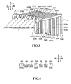
Fig. 3 is a diagrammatic front, top and right side perspective view of first and second signal terminals and ground terminals of the connector. -
Fig. 4 is a schematic end view of the cross-section along 4-4 inFig. 3 of the first and second signal terminals and the ground terminals. -
Fig. 5 is a diagrammatic perspective view of a variant of the first and second signal terminals. -
Fig. 6 is a schematic end view of a cross-section of the first and second signal terminals and the ground terminals for describing a design modification of the ground terminals. -
Fig. 7 is a diagrammatic perspective view showing another design modification of the ground terminal. -
Fig. 8A is an explanatory view showing a design modification of a terminal group of the connector. -
Fig. 8B is an explanatory view showing another design modification of the terminal group of the connector. - In the description which follows, relative spatial terms such as "upper", "lower", "upwardly", "top", "bottom", "right", "front", "back", "rear", etc., are used for the convenience of the skilled reader and refer to the orientation of the connector and its constituent parts as depicted in the drawings. No limitation is intended by use of these terms, either in use of the invention, during its manufacture, shipment, custody, or sale, or during assembly of its constituent parts or when incorporated into or combined with other apparatus.
- A connector according to an embodiment of the present invention will be described below referring to
Figs. 1 to 4 . The connector shown inFig. 1 is a receptacle connector mountable on a circuit board (not shown) and connectable with a plug connector (not shown). The connector includes abody 100, ashell 200, and a terminal group C. Respective components of the connector will be described in detail below. It should be noted thatFigs. 1 to 4 indicate directions X, Y, and Z, where the X direction is a first direction, which is a widthwise direction of the connector and an array direction of the terminal group C; the Y direction is a second direction, which is a front-back direction of the connector and is orthogonal to the first direction X; and the Z direction is a third direction, which is a top-bottom direction of the connector and is orthogonal to the first and second directions X and Y - The
body 100 of rectangular parallelepiped shape is made of insulating resin. Thebody 100 has amain body 110 and aprojection 120, as shown inFigs. 1 and2 . The front surface in the second direction Y of themain body 110 has a substantiallyrectangular reception hole 111 for removably receiving a plug connector. Theprojection 120 extends from a back-side surface in the second direction Y of thereception hole 111. Theprojection 120 is a rectangular plate extending in the first direction X and the second direction Y. An upper surface of theprojection 120 is formed with a plurality ofgrooves 121 extending in the second direction Y. - The
shell 200 is a rectangular tube made of an electrically conductive metal plate, covering the outer peripheral surface of thebody 100, as shown inFig. 1 andFigs. 2A, 2B . - The terminal group C includes a pair of
first signal terminals 310S, a pair ofsecond signal terminals 320S, and a plurality ofground terminals 330G, as shown inFigs. 1 to 4 . In the terminal group C, the first and second signal terminals and the ground terminals are arrayed in a row along the first direction X inside thebody 100 in an order of 330G, 310S, 310S, 330G, 320S, 320S, and 330G (i.e., the terminal group C is arrayed in a row along the first direction X inside the body 100). - As shown in
Figs. 2A and3 , the pair offirst signal terminals 310S are next to each other in the first direction X to form a differential pair for transmission of high-speed differential signals of 1 GHz or higher. Thefirst signal terminals 310S are electrically conductive metal plates extending in the second direction Y. Each of thefirst signal terminals 310S has anintermediate portion 311 S, acontact portion 312S, abent portion 313S, and atail portion 314S. - The
intermediate portion 311S is a plate extending in the second direction Y, and it is embedded in and held by themain body 110 of thebody 100. Theintermediate portion 311S has a first end and a second end in the second direction Y, and thecontact portion 312S is provided continuously to the first end and thebent portion 313S is provided continuously to the second end. - The
contact portion 312S is a plate extending in the second direction Y continuously to theintermediate portion 311 S. Thecontact portion 312S is received in each of thegrooves 121 of theprojection 120 of thebody 100. Thecontact portion 312S has a curved portion of a circular arc shape that is curved upwardly in the third direction Z. The curved portion is contactable with a signal contact of the above-mentioned plug connector. - The bent portion 3135 is a substantially L-shaped plate bent at a right angle to the
intermediate portion 311S, and it extends in the third direction Z along a rear surface in the second direction Y of themain body 110. Thetail portion 314S is a plate provided continuously to a lower end in the third direction Z of thebent portion 313S and bent at a right angle to thebent portion 313S to extend in the second direction Y. Thetail portion 314S is connectable to a signal line of the circuit board. - As shown in
Fig. 3 , the pair ofsecond signal terminals 320S are next to each other in the first direction X to form a differential pair for transmission of high-speed differential signals of I GHz or higher. Thesecond signal terminals 320S are electrically conductive metal plates extending in the second direction Y, and they have the same configuration as thefirst signal terminals 310S. Thesecond signal terminals 320S each have anintermediate portion 321 S, acontact portion 322S, abent portion 323S, and atail portion 324S. The respective portions of thesecond signal terminal 320S will not be described further in detail to avoid redundancy with the description of thefirst signal terminal 310S. - As shown in
Figs. 2B and3 , theground terminals 330G are electrically conductive metal plates extending in the second direction Y. They each have the substantially same outer shape, except its thicknesswise dimension, as each outer shape of the first andsecond signal terminals ground terminals 330G each have the same dimension in the first direction X as each of the first andsecond signal terminals Figs. 3 and 4 , the thicknesswise dimension (plate thickness) of eachground terminal 330G is larger than or equal to 1.5 times that of each of the first andsecond signal terminals ground terminals 330G is disposed between one of the pairedfirst signal terminals 310S and one of the pairedsecond signal terminals 320S; anotherground terminal 330G is disposed on a side (outer side) of the opposite sides of the otherfirst signal terminal 310S, the side being opposite from said one of thefirst signal terminals 310S; and theother ground terminal 330G is disposed on a side (outer side) of opposite sides of the othersecond signal terminal 320S, the side being opposite from said one of thesecond signal terminals 320S. In other words, theground terminals 330G are arrayed in the first direction; the pair of first signal terminals 3105 are each interposed between adjacent two of theground terminals 330G; and the pair ofsecond signal terminals 320S are each interposed between another adjacent two of theground terminals 330G. - The
ground terminals 330G each have anintermediate portion 331G, acontact portion 332G, abent portion 333G, and atail portion 334G Theintermediate portion 331 G is a plate extending in the second direction Y, and it is embedded in and held by themain body 110 of thebody 100. The thicknesswise dimension in the third direction Z (plate thickness) of eachintermediate portion 331 G is larger or equal to 1.5 times that of eachintermediate portion second signal terminals Fig. 4 illustratescenters 03 of cross-sections in the third direction Z of theintermediate portions 331 G (eachintermediate portion 331 G being a part of the portion where the thicknesswise dimension of each ground terminal is larger than that of each of the first and second signal terminals).Fig. 4 also illustrates centers O1, 02 of cross-sections in the third direction Z of theintermediate portions centers 03 are located substantially at the same height in the third direction Z as the centers O1, 02. Eachintermediate portion 331 G has first and second ends in the second direction Y, and thecontact portion 332G is provided continuously to the first end, and thebent portion 333G is provided continuously to the second end. - The
contact portion 332G is a plate extending in the second direction Y continuously from theintermediate portion 331G. The thicknesswise dimension in the third direction Z (plate thickness) of thecontact portion 332G is larger than or equal to 1.5 times that of each of thecontact portions signal terminals contact portion 332G is received in each of thegrooves 121 in theprojection 120 of thebody 100. Thecontact portion 332G has a curved portion in a circular arc shape that is curved upwardly in the third direction Z. The curved portion is contactable with a ground contact of the above-mentioned plug connector. - The
bent portion 333G is a substantially L-shaped plate bent at a right angle to theintermediate portion 331 G to extend in the third direction Z along the rear surface in the second direction Y of themain body 110. The thicknesswise dimension in the second direction Y (plate thickness) of thebent portion 333G is larger than or equal to 1.5 times that of each of thebent portions signal terminals - The
tail portion 334G is a plate provided continuously to a lower end in the third direction Z of thebent portion 333G and bent at a right angle to thebent portion 333G to extend in the second direction Y. A thicknesswise dimension in the third direction Z (plate thickness) of thetail portion 334G is larger than or equal to 1.5 times that of each of thetail portions signal terminals tail portion 314S is contactable with a ground line of the circuit board. - The connector may be configured as described above and may be manufactured in the following manner. First, a first metal plate having electrical conductivity is prepared. The metal plate is then pressed, using a predetermined stamping die to form the first and
second signal terminals ground terminals 330G - Thereafter, the
body 100 is formed by injection-molding insulating resin. When thebody 100 is formed, theintermediate portions 311S of thefirst signal terminals 310S, theintermediate portions 321S of thesecond signal terminals 320S, and theintermediate portions 331 G of theground terminals 330G are inserted in themain body 110, i.e. theintermediate portions main body 110 of thebody 100. As a result, the first and second signal terminals and the ground terminals are arrayed in a row along the first direction X inside thebody 100 in the order of 330G, 310S, 310S, 330G, 320S, 320S, and 330G. Thecontact portions 312S of thefirst signal terminals 310S, thecontact portions 322S of thesecond signal terminals 320S, and thecontact portions 332G of theground terminals 330G are received in thegrooves 121 of theprojection 120 of thebody 100. - The
body 100 is then inserted into theshell 200. The connector is now finished and ready to be mounted on the circuit board. At this time, theshell 200 is connected to the ground line of the circuit board, thetail portions tail portions 334G are connected to the ground line of the circuit board by soldering. - In the above-described connector, the
ground terminals 330G each have the same dimension in the first direction X as each of the first andsecond signal terminals ground terminals 330G each have a thicknesswise dimension (plate thickness) equal to or larger than 1.5 times that of each of the first andsecond signal terminals ground terminal 330G is advantageously reduced in conductor resistance and ground potential. The connector, having one of theground terminals 330G disposed between the pair offirst signal terminals 310S and the pair ofsecond signal terminals 320S, is able to reduce crosstalk between signals transmitted by thefirst signal terminals 310S and signals transmitted by thesecond signal terminals 320S. Further advantageously, the connector has a reduced widthwise dimension in the first direction because theground terminals 330G each have the same dimension in the first direction X as each of the first andsecond signal terminals - Furthermore, the
ground terminals 330G each have a larger plate thickness than each of thefirst signal terminals 310S and thesecond signal terminals 320S, and they are located on the opposite sides of thefirst signal terminals 310S and on the opposite sides of thesecond signal terminals 320S. As such, theground terminals 330G function as shield walls against electric field leakage from the first andsecond signal terminals ground terminals 330G are located on the opposite sides of thefirst signal terminals 310S and on the opposite sides of thesecond signal terminals 320S, and thecenters 03 of theintermediate portions 331G of theground terminals 330G are located substantially at the same height in the third direction Z as the centers O1, 02 of theintermediate portions second signal terminals first signal terminals 310S and thesecond signal terminals 320S and improving transmission characteristics of the first andsecond signal terminals - The connector of the invention is not limited to the above-described embodiment, but it may be modified within a scope described in the claims. Variations of the invention will be described in detail below by way of example.
- The first and second signal terminals of the invention are not limited to the case according to above-described embodiment, wherein the first and
second signal terminals - The first and second signal terminals of the invention may be configured like the first and
second signal terminals intermediate portions contact portions bent portions tail portions Fig. 5 , where first andsecond signal terminals 310S', 320S' are electrically conductive plates generally extending in the first direction X and the second direction Y. In this case,intermediate portions 311S', 321 S',contact portions 312S', 322S', andtail portions 314S', 324S' are plates extending in the first direction X and the second direction Y. Thebent portions 313S', 323S' are substantially L-shaped plates bent at a right angle to theintermediate portions 311 S', 321 S' and extending in the first direction X and the third direction Z. - The ground terminal of the invention may be configured like the
ground terminals 330G of the above-described embodiment, wherein eachground terminal 330G has theintermediate portion 331G, thecontact portion 332G, thebent portion 333G, and thetail portion 334G, and it has the substantially identical outer shape, except its thicknesswise dimension, to those of the first andsecond signal terminals - In the case where the first signal terminals and the second signal terminals have different shapes, in the case where one of the first signal terminals and one of the second signal terminals have the same shape to each other but different from the other first signal terminal and the other second signal terminal, respectively, or in the case where all the first and second signal terminals have different shapes from each other, the ground terminal may have substantially the same outer shape, except its thicknesswise dimension, as that of at least one of the first signal terminals, or at least one of the second signal terminals. An alternative modification is illustrated in
Fig. 6 , wherein eachground terminals 330G' has a smaller widthwise dimension in the first direction X than each of the first andsecond signal terminals Fig. 6 shows a center 03', which is the center of a cross-section in the third direction Z of eachground terminals 330G'. - Moreover, in the case where the ground terminal and the first and second signal terminals are straight in shape and extend in the second direction or the like, the ground terminal may have a larger thicknesswise dimension in the third direction from end to end than each of the first and second signal terminals. Alternatively, the ground terminal may have a larger thicknesswise dimension in the third direction at its intermediate portion than each of the first and second signal terminals. An alternative modification is illustrated in
Fig. 7 , wherein aground terminal 330G" is an electrically conductive plate generally extending in the second direction Y and the third direction Z. In this case, anintermediate portion 331G", acontact portion 332G", abent portion 333G", and atail portion 334G" are plates extending in the second direction Y and the third direction Z. Theground terminal 330G" may be disposed between one of thefirst signal terminals 310S and one of thesecond signal terminals 320S, or between one of thefirst signal terminals 310S' and one of thesecond signal terminals 320S'. Moreover,additional ground terminals 330G" may be provided, one on a side of the two sides of the otherfirst signal terminal first signal terminals ground terminal 330G" on a side of the two sides of the othersecond signal terminal second signal terminal first signal terminals 310S may each be disposed between adjacent two of theground terminals 330G"; thesecond signal terminals 320S may each be disposed between adjacent two of theground terminals 330G"; thefirst signal terminals 310S' may each be disposed between adjacent two of theground terminals 330G"; and thesecond signal terminals 320S' may each be disposed between adjacent two of theground terminals 330G". - The height positions of the terminals are not limited to those of the above-described embodiment, wherein the centers O3 of the
intermediate portions 331 G of theground terminals 330G are located substantially at the same height in the third direction Z as the centers O1, O2 of theintermediate portions second signal terminals - The body may be formed by insert molding with the intermediate portions of the first and second signal terminals and the ground terminals inserted therein as in the above embodiment. Any design modification may be made as long as the terminals are held in the body and arrayed at least in one row. For example, the body may be formed with through-holes extending in the second direction Y, which may receive the intermediate portions of the first and second signal terminals and the ground terminals.
- The ground terminals according to the above embodiment and design modifications may be arranged such that one is disposed between one of the pair of first signal terminals and one of the pair of second signal terminals, another on one of the opposite sides of the other first signal terminal that is opposite from the one of the first signal terminals, and the other on one of the opposite sides of the other second signal terminal that is opposite from the one of the second signal terminals. The ground terminals may be disposed at any other positions, each between two adjacent signal terminals. For example, there may be a single ground terminal disposed between one of the pair of first signal terminals and one of the pair of second signal terminals. Alternatively, a ground terminal may be disposed between the one of the first signal terminals and a different signal terminal (which may be a second signal terminal). In other words, a ground terminal may be disposed between a terminal of a differential pair and a signal terminal of other kind. In any of the above arrangements, the first and second signal terminals and the ground terminal are arrayed in a row in the first direction as in the above-described embodiment.
- Alternatively, ground terminals may be arranged between a plurality of signal terminals for single-end or other transmission. The ground terminals may be arranged as shown in
Figs. 8A and 8B , wherein the ground terminals G or G' are disposed between signal terminals S for single-end or other transmission and on the outside of the signal terminals S at opposite ends in the first direction X. In other words, the ground terminals G or G' are arranged in spaced relation to each other along the first direction; and the signal terminals S are each disposed between adjacent two of the ground terminals G or G'. A reference character C' inFig. 8A denotes a terminal group having the ground terminals G and the signal terminals S arrayed in a row along the first direction X in a body not shown. A reference character C" inFig. 8B denotes a terminal group having the ground terminals G' and the signal terminals S arrayed in a row along the first direction X in a body not shown. - The signal terminals S may be of any shape extending in the second direction orthogonal to the first direction X. For example, the signal terminals S may be of similar shape to those of the first and
second signal terminals - The ground terminals G, G' may be modified in any manner on the following conditions. A first condition is that the ground terminals are electrically conductive members extending in the second direction. A second condition is that each ground terminal have a widthwise dimension in the first direction equal to or smaller than twice that of each signal terminal. A third condition is that each ground terminal, at least a portion thereof, has a larger thicknesswise dimension in the third direction than each signal terminal. Accordingly, as in the ground terminals G shown in
Fig. 8A , each ground terminal between signal terminals may have substantially the same shape, except its the thicknesswise dimension, as each signal terminal. Alternatively, as in the ground terminals G' shown inFig. 8B , each ground terminal between signal terminals may have a smaller widthwise dimension in the first direction X than each signal terminal. As to the third condition, it is preferable that each ground terminal, at least a portion thereof, has a thicknesswise dimension in the third direction equal to or larger than 1.5 times that of each signal terminal at a portion corresponding to the said portion of each ground terminal. - Moreover, the ground terminals G, G' and the signal terminal may be straight in shape and extend in the second direction, in which case the ground terminals G or G' may each have a larger thicknesswise dimension in the third direction from end to end than each signal terminal. Alternatively, each ground terminal G or G' may have a larger thicknesswise dimension in the third direction at its intermediate portion than the intermediate portion of each signal terminal. Furthermore, each ground terminal G or G' may have a similar configuration to those of the
ground terminals - Moreover, as shown in
Figs. 8A and 8B , the arrangement of ground terminals between signal terminals may be such that the centers of cross-sections in the third direction of the portions (parts) of the ground terminals G or G', which portions are each of larger thicknesswise dimension in the third direction than each signal terminal S, are located at substantially the same height position as the centers of cross-sections in the third direction of the portions of the signal terminals S corresponding to the said parts of the ground terminals. Alternatively, the centers of the ground terminals G or G' and the centers of the signal terminals S may be at different heights in the third direction. - The terminal group may be arrayed in a row in the body as described above, but the array may be modified as long as the first and second signal terminals (or the signal terminals) and the ground terminals are arrayed at least in a row in the body. That is, the terminal group may have a configuration in which the first and second signal terminals (or the signal terminals) and the ground terminals are arrayed in two or more rows in the body. The terminal group may have the pair of first signal terminals, the pair of second signal terminals, and the plurality of ground terminals as in the above-described embodiment. Alternatively, the terminal group may have a plurality of pairs of first signal terminals, a plurality of pairs of second signal terminals, and a plurality of ground terminals. In this case, some of the ground terminals may be arranged such that each ground terminal is disposed between each pair of first signal terminals and each pair of second signal terminals. Other ground terminals may be disposed on the outside of the contacts at opposite ends in the first direction of all the first and second signal terminals.
- The materials, shapes, sizes, numbers, arrangements, etc. of the respective elements of the connector have been described by way of example only, and they may be modified in design in any manner as long as they provide similar functions. The connector of the invention may be a receptacle connector as in the embodiment, but it may be a plug connector. The first and second signal terminals are not limited to the use for transmitting high-speed differential signals as in the above-described embodiment. The first and second signal terminals and the signal terminals may be applicable to transmission of any kind of signals at any frequencies.
-
- 100
- body
- 110
- main body
- 120
- projection
- 200
- shell
- C
- terminal group
- 310S
- first signal terminal
- 311S
- intermediate portion
- 312S
- contact portion
- 313S
- bent portion
- 314S
- tail portion
- 320S
- second signal terminal
- 321S
- intermediate portion
- 322S
- contact portion
- 323S
- bent portion
- 324S
- tail portion
- 330G
- ground terminal
- 331G
- intermediate portion
- 332G
- contact portion
- 333G
- bent portion
- 334G
- tail portion
- X
- first direction
- Y
- second direction
- Z
- third direction
Claims (15)
- A connector comprising:a body (100) having insulation properties; anda terminal group (C), the terminal group (C) including a plurality of signal terminals (310S, 320S) and a ground terminal (330G), the signal terminals (310S, 320S) and the ground terminal (330G) being arrayed in a row along a first direction (X) in the body, whereinthe signal terminals (310S, 320S) extend in a second direction (Y) orthogonal to the first direction (X),the ground terminal (330G) extends in the second direction (Y) and is disposed between two adjacent ones of the signal terminals (310S, 320S),a widthwise dimension in the first direction (X) of the ground terminal (330G) is less than twice that of each of the signal terminals (3105, 320S), anda thicknesswise dimension of at least a part of the ground terminal (330G) in a third direction (Z) orthogonal to the first (X) and second (Y) directions is larger than that of each of the signal terminals (310S, 320S).
- The connector according to claim 1, wherein
the ground terminal (330G) comprises a plurality of ground terminals (330G) arranged in spaced relation to each other along the first direction (X), and
the signal terminals (310S, 320S) are each interposed between adjacent two of the ground terminals (330G). - The connector according to claim 1 or claim 2, wherein a center of a cross-section (O3) in the third direction (Z) of said part of the ground terminal (330G) is located substantially at the same height in the third direction (Z) as centers of cross-sections (O1, O2) in the third direction (Z) of portions of the signal terminals (310S, 320S) corresponding to said part of the ground terminal (330G).
- The connector according to any preceding claim, wherein the widthwise dimension in the first direction (X) of the ground terminal (330G) is smaller than that of each of the signal terminals (310S, 320S).
- The connector according to any of claims 1 to 3, wherein the ground terminal (330G) has a generally identical outer shape, except the thicknesswise dimension thereof, to that of each of the signal terminals (31 0S 320S).
- The connector according to any preceding claim, wherein
the signal terminals (310S, 320S) are electrically conductive plates extending not only in the second direction (Y) but also in the first direction (X), and
the ground terminal (330G) is an electrically conductive plate extending not only in the second direction (Y) but also in the third direction (Z). - The connector according to any preceding claim, wherein the thicknesswise dimension in the third direction (Z) of at least said part of the ground terminal (330G) is 1.5 times or larger than that of each of the signal terminals (310S, 320S).
- The connector according to claim 1, wherein
the signal terminals include a pair of first signal terminals (310S) and a second signal terminal (320S),
the pair of first signal terminals (310S) extends in the second direction (Y) and the first signal terminals (310S) are adjacent to each other in the first direction (X),
the second signal terminal (320S) extends in the second direction (Y),
the ground terminal (330G) is disposed between one of the first signal terminals (310S) and the second signal terminal (320S),
the widthwise dimension in the first direction (X) of the ground terminal (330G) is less than twice that of each of the first signal terminals (310S), and
the thicknesswise dimension in the third direction (Z) of at least said part of the ground terminal (330G) is larger than that of each of the first (310S) and second (320S) signal terminals. - The connector according to claim 8, wherein
the second terminal (320S) of the terminal group (C) comprises a pair of second signal terminals (320S) adjacent to each other in the first direction (X), and
the ground terminal (330G) is disposed between the one first signal terminal (310S) and one of the second signal terminals (320S). - The connector according to claim 9, wherein
the ground terminal (330G) comprises a plurality of ground terminals (330G) arranged in spaced relation to each other along the first direction (X),
the pair of first signal terminals (310S) is interposed between adjacent two of the ground terminals (330G), and
the pair of second signal terminals (320S) is interposed between another adjacent two of the ground terminals (330G). - The connector according to claim 9 or claim 10, wherein a center of a cross-section (O3) in the third direction (Z) of said part of the ground terminal (330G) is located substantially at the same height in the third direction (Z) as centers of cross-sections (O1, O2) in the third direction (Z) of portions of the first (310S) and second (320S) signal terminals corresponding to said part of the ground terminal (330G).
- The connector according to any one of claims 8 to 11, wherein the widthwise dimension in the first direction (X) of the ground terminal (330G) is smaller than the widthwise dimension in the first direction (X) of at least one of the first (310S) and second (320S) signal terminals.
- The connector according to any one of claims 8 to 11, wherein the ground terminal (330G) has a generally identical outer shape, except the thicknesswise dimension thereof, to that of at least one of the first (310S) and second (320S) signal terminals.
- The connector according to any one of claims 8 to 13, wherein
the first (310S) and second (320S) signal terminals are electrically conductive plates extending not only in the second direction (Y) but also in the first direction (X), and
the ground terminal (330G) is an electrically conductive plate extending not only in the second direction (Y) but also in the third direction (Z). - The connector according to any one of claims 8 to 14, wherein the thicknesswise dimension in the third direction (Z) of at least said part of the ground terminal (330G) is 1.5 times or larger than that of each of the first (310S) and second (320S) signal terminals.
Applications Claiming Priority (1)
| Application Number | Priority Date | Filing Date | Title |
|---|---|---|---|
| JP2011094396A JP2012227025A (en) | 2011-04-20 | 2011-04-20 | Connector |
Publications (1)
| Publication Number | Publication Date |
|---|---|
| EP2515385A1 true EP2515385A1 (en) | 2012-10-24 |
Family
ID=45954289
Family Applications (1)
| Application Number | Title | Priority Date | Filing Date |
|---|---|---|---|
| EP12002308A Withdrawn EP2515385A1 (en) | 2011-04-20 | 2012-03-29 | Connector |
Country Status (5)
| Country | Link |
|---|---|
| US (1) | US8672691B2 (en) |
| EP (1) | EP2515385A1 (en) |
| JP (1) | JP2012227025A (en) |
| CN (1) | CN102751625A (en) |
| TW (1) | TW201244292A (en) |
Cited By (2)
| Publication number | Priority date | Publication date | Assignee | Title |
|---|---|---|---|---|
| CN105703107A (en) * | 2014-10-21 | 2016-06-22 | 泰科电子公司 | Electrical connector having bussed ground contacts |
| EP3675285A1 (en) * | 2018-12-25 | 2020-07-01 | Foxconn Interconnect Technology Limited | Electrical connector assembly |
Families Citing this family (10)
| Publication number | Priority date | Publication date | Assignee | Title |
|---|---|---|---|---|
| EP2840667B1 (en) * | 2007-12-20 | 2018-05-16 | TRW Automotive U.S. LLC | Electronic assembly and method of manufacturing same |
| US9590358B2 (en) * | 2012-09-28 | 2017-03-07 | Molex, Llc | Electrical connector having staggered pins |
| JP5595538B2 (en) | 2013-02-20 | 2014-09-24 | 日本航空電子工業株式会社 | connector |
| JP6234876B2 (en) * | 2014-04-23 | 2017-11-22 | ホシデン株式会社 | Connector and connector manufacturing method |
| TWI586052B (en) * | 2014-12-19 | 2017-06-01 | 連展科技股份有限公司 | Socket electrical connector |
| US9509098B1 (en) * | 2015-11-18 | 2016-11-29 | Tyco Electronics Corporation | Pluggable connector having bussed ground conductors |
| CN205960264U (en) * | 2016-07-27 | 2017-02-15 | 广东欧珀移动通信有限公司 | Power source , mobile terminal and power adapter |
| CN206225604U (en) * | 2016-09-22 | 2017-06-06 | 番禺得意精密电子工业有限公司 | Composite connector |
| JP7522698B2 (en) * | 2021-04-28 | 2024-07-25 | ヒロセ電機株式会社 | Electrical connector and electrical connector with circuit board |
| TWI856923B (en) * | 2024-02-07 | 2024-09-21 | 美商莫仕有限公司 | Line-end connector and combination of line-end connector and board-end connector |
Citations (3)
| Publication number | Priority date | Publication date | Assignee | Title |
|---|---|---|---|---|
| JPH07161414A (en) | 1993-12-08 | 1995-06-23 | Japan Aviation Electron Ind Ltd | connector |
| US20030064626A1 (en) * | 2001-09-28 | 2003-04-03 | Kemmick Dennis L. | Connector with staggered contact pattern |
| WO2008002376A2 (en) * | 2006-06-27 | 2008-01-03 | Fci Americas Technology, Inc. | Electrical connector with elongated ground contacts |
Family Cites Families (16)
| Publication number | Priority date | Publication date | Assignee | Title |
|---|---|---|---|---|
| JP2000252017A (en) * | 1999-02-25 | 2000-09-14 | Fujitsu Takamisawa Component Ltd | Connector structure |
| DE60014385T2 (en) * | 1999-07-16 | 2006-02-23 | Molex Inc., Lisle | IMPEDANCE-CONNECTED CONNECTOR |
| TW456619U (en) * | 1999-07-16 | 2001-09-21 | Molex Inc | Impedance-tuned termination assembly and connectors incorporating same |
| US7039417B2 (en) * | 2003-09-25 | 2006-05-02 | Lenovo Pte Ltd | Apparatus, system, and method for mitigating access point data rate degradation |
| US6863549B2 (en) * | 2002-09-25 | 2005-03-08 | Molex Incorporated | Impedance-tuned terminal contact arrangement and connectors incorporating same |
| CN100474708C (en) * | 2002-09-25 | 2009-04-01 | 莫莱克斯公司 | Impedance-tuned terminal contact arrangement and connectors incorporating the same |
| JP2005149770A (en) * | 2003-11-11 | 2005-06-09 | Japan Aviation Electronics Industry Ltd | connector |
| JP2005190820A (en) * | 2003-12-25 | 2005-07-14 | Fujitsu Component Ltd | Connector assembly |
| US20060245137A1 (en) * | 2005-04-29 | 2006-11-02 | Fci Americas Technology, Inc. | Backplane connectors |
| JP4917784B2 (en) * | 2005-09-26 | 2012-04-18 | 富士通コンポーネント株式会社 | connector |
| CN101106229B (en) * | 2006-07-14 | 2010-06-02 | 日本航空电子工业株式会社 | Electronic components in which contact terminal portions are arranged in a substantially trapezoidal shape |
| CN201117870Y (en) * | 2007-11-12 | 2008-09-17 | 富士康(昆山)电脑接插件有限公司 | electrical connector |
| JP5100449B2 (en) * | 2008-03-05 | 2012-12-19 | キヤノン株式会社 | Composite connector and electronic device including the same |
| JP5039690B2 (en) * | 2008-12-25 | 2012-10-03 | ホシデン株式会社 | Multi-pole connector |
| CN102315534B (en) * | 2010-07-08 | 2014-08-20 | 泰科电子(上海)有限公司 | Electric connector |
| US8419457B2 (en) * | 2011-08-26 | 2013-04-16 | Concraft Holding Co., Ltd. | Anti-electromagnetic interference electrical connector and terminal assembly thereof |
-
2011
- 2011-04-20 JP JP2011094396A patent/JP2012227025A/en active Pending
-
2012
- 2012-02-21 TW TW101105624A patent/TW201244292A/en unknown
- 2012-03-23 US US13/428,119 patent/US8672691B2/en not_active Expired - Fee Related
- 2012-03-29 EP EP12002308A patent/EP2515385A1/en not_active Withdrawn
- 2012-04-18 CN CN2012101148149A patent/CN102751625A/en active Pending
Patent Citations (3)
| Publication number | Priority date | Publication date | Assignee | Title |
|---|---|---|---|---|
| JPH07161414A (en) | 1993-12-08 | 1995-06-23 | Japan Aviation Electron Ind Ltd | connector |
| US20030064626A1 (en) * | 2001-09-28 | 2003-04-03 | Kemmick Dennis L. | Connector with staggered contact pattern |
| WO2008002376A2 (en) * | 2006-06-27 | 2008-01-03 | Fci Americas Technology, Inc. | Electrical connector with elongated ground contacts |
Cited By (4)
| Publication number | Priority date | Publication date | Assignee | Title |
|---|---|---|---|---|
| CN105703107A (en) * | 2014-10-21 | 2016-06-22 | 泰科电子公司 | Electrical connector having bussed ground contacts |
| CN105703107B (en) * | 2014-10-21 | 2019-05-28 | 泰连公司 | Electric connector with bus grounding contact |
| EP3675285A1 (en) * | 2018-12-25 | 2020-07-01 | Foxconn Interconnect Technology Limited | Electrical connector assembly |
| US11056813B2 (en) | 2018-12-25 | 2021-07-06 | Foxconn (Kunshan) Computer Connector Co., Ltd. | Electrical connector assembly with complementary contact unit |
Also Published As
| Publication number | Publication date |
|---|---|
| CN102751625A (en) | 2012-10-24 |
| US20120270445A1 (en) | 2012-10-25 |
| JP2012227025A (en) | 2012-11-15 |
| TW201244292A (en) | 2012-11-01 |
| US8672691B2 (en) | 2014-03-18 |
Similar Documents
| Publication | Publication Date | Title |
|---|---|---|
| US8672691B2 (en) | Connector | |
| US9793633B2 (en) | Electrical connector with a grounding bar connecting the terminals of a plurality of ground contact wafers and shielding braids of cables | |
| JP5059898B2 (en) | Electrical connector | |
| US9742095B2 (en) | Electrical receptacle connector | |
| US8851927B2 (en) | Electrical connector with shielding and grounding features thereof | |
| US9214766B1 (en) | Electrical connector having a metallic inner shell between a metallic outer shell and an insulative housing | |
| US9059543B2 (en) | Cable connector assembly having a shell contacting a grounding pad of an internal printed circuit board | |
| US9478915B2 (en) | Electrical connector having power terminals in an upper row in contact with those in a lower row | |
| US9647393B2 (en) | Electrical receptacle connector | |
| US11075490B2 (en) | Electrical receptacle connector with elastic contacts | |
| US10153566B2 (en) | Electrical connector having an improved terminal | |
| US7815467B2 (en) | Connector device | |
| TWI573350B (en) | Socket electrical connector | |
| EP2339702B1 (en) | Connector | |
| TWI594513B (en) | Plug connector and connector assembly | |
| US9257797B2 (en) | Cable assembly having an improved circuit board | |
| US20180076555A1 (en) | Electrical connector assembly | |
| US20150072546A1 (en) | Electrical connector with grounding plate | |
| US6749463B1 (en) | Shielded board mounted electrical connector | |
| US20120071032A1 (en) | Electrical receptacle | |
| US9276330B2 (en) | Cable connector assembly having a conductive element for connecting grounding layers of the cable together | |
| US11031725B2 (en) | Electrical receptacle connector | |
| US20130337685A1 (en) | Electrical connector with detect function | |
| US8070531B1 (en) | Keystone jack | |
| US20180013218A1 (en) | High power plug connector |
Legal Events
| Date | Code | Title | Description |
|---|---|---|---|
| PUAI | Public reference made under article 153(3) epc to a published international application that has entered the european phase |
Free format text: ORIGINAL CODE: 0009012 |
|
| AK | Designated contracting states |
Kind code of ref document: A1 Designated state(s): AL AT BE BG CH CY CZ DE DK EE ES FI FR GB GR HR HU IE IS IT LI LT LU LV MC MK MT NL NO PL PT RO RS SE SI SK SM TR |
|
| AX | Request for extension of the european patent |
Extension state: BA ME |
|
| 17P | Request for examination filed |
Effective date: 20130320 |
|
| RIC1 | Information provided on ipc code assigned before grant |
Ipc: H01R 13/6471 20110101ALI20150706BHEP Ipc: H01R 24/64 20110101AFI20150706BHEP Ipc: H01R 107/00 20060101ALN20150706BHEP |
|
| GRAP | Despatch of communication of intention to grant a patent |
Free format text: ORIGINAL CODE: EPIDOSNIGR1 |
|
| RIC1 | Information provided on ipc code assigned before grant |
Ipc: H01R 13/6471 20110101ALI20151012BHEP Ipc: H01R 24/64 20110101AFI20151012BHEP Ipc: H01R 107/00 20060101ALN20151012BHEP |
|
| INTG | Intention to grant announced |
Effective date: 20151110 |
|
| STAA | Information on the status of an ep patent application or granted ep patent |
Free format text: STATUS: THE APPLICATION IS DEEMED TO BE WITHDRAWN |
|
| 18D | Application deemed to be withdrawn |
Effective date: 20160322 |