EP2515360A1 - Battery module - Google Patents
Battery module Download PDFInfo
- Publication number
- EP2515360A1 EP2515360A1 EP20110190419 EP11190419A EP2515360A1 EP 2515360 A1 EP2515360 A1 EP 2515360A1 EP 20110190419 EP20110190419 EP 20110190419 EP 11190419 A EP11190419 A EP 11190419A EP 2515360 A1 EP2515360 A1 EP 2515360A1
- Authority
- EP
- European Patent Office
- Prior art keywords
- battery module
- bottom plate
- battery
- module according
- battery cells
- Prior art date
- Legal status (The legal status is an assumption and is not a legal conclusion. Google has not performed a legal analysis and makes no representation as to the accuracy of the status listed.)
- Granted
Links
- 239000000463 material Substances 0.000 claims description 12
- 230000004888 barrier function Effects 0.000 claims description 8
- 239000004033 plastic Substances 0.000 claims description 4
- 230000001419 dependent effect Effects 0.000 claims 2
- 238000004519 manufacturing process Methods 0.000 description 7
- 230000003252 repetitive effect Effects 0.000 description 7
- 229910000831 Steel Inorganic materials 0.000 description 4
- 239000003792 electrolyte Substances 0.000 description 4
- 238000000034 method Methods 0.000 description 4
- 239000010959 steel Substances 0.000 description 4
- 239000002826 coolant Substances 0.000 description 3
- 238000003487 electrochemical reaction Methods 0.000 description 3
- 230000003247 decreasing effect Effects 0.000 description 2
- 235000012773 waffles Nutrition 0.000 description 2
- 238000003491 array Methods 0.000 description 1
- 230000007423 decrease Effects 0.000 description 1
- 230000006866 deterioration Effects 0.000 description 1
- 238000007599 discharging Methods 0.000 description 1
- 230000001788 irregular Effects 0.000 description 1
- 239000003562 lightweight material Substances 0.000 description 1
- 238000012986 modification Methods 0.000 description 1
- 230000004048 modification Effects 0.000 description 1
- 239000011255 nonaqueous electrolyte Substances 0.000 description 1
- 238000007789 sealing Methods 0.000 description 1
- 238000007086 side reaction Methods 0.000 description 1
- 229920001169 thermoplastic Polymers 0.000 description 1
- 239000004416 thermosoftening plastic Substances 0.000 description 1
Images


Classifications
-
- H—ELECTRICITY
- H01—ELECTRIC ELEMENTS
- H01M—PROCESSES OR MEANS, e.g. BATTERIES, FOR THE DIRECT CONVERSION OF CHEMICAL ENERGY INTO ELECTRICAL ENERGY
- H01M50/00—Constructional details or processes of manufacture of the non-active parts of electrochemical cells other than fuel cells, e.g. hybrid cells
- H01M50/50—Current conducting connections for cells or batteries
-
- H—ELECTRICITY
- H01—ELECTRIC ELEMENTS
- H01M—PROCESSES OR MEANS, e.g. BATTERIES, FOR THE DIRECT CONVERSION OF CHEMICAL ENERGY INTO ELECTRICAL ENERGY
- H01M10/00—Secondary cells; Manufacture thereof
- H01M10/60—Heating or cooling; Temperature control
- H01M10/65—Means for temperature control structurally associated with the cells
-
- H—ELECTRICITY
- H01—ELECTRIC ELEMENTS
- H01M—PROCESSES OR MEANS, e.g. BATTERIES, FOR THE DIRECT CONVERSION OF CHEMICAL ENERGY INTO ELECTRICAL ENERGY
- H01M10/00—Secondary cells; Manufacture thereof
- H01M10/60—Heating or cooling; Temperature control
- H01M10/62—Heating or cooling; Temperature control specially adapted for specific applications
- H01M10/625—Vehicles
-
- H—ELECTRICITY
- H01—ELECTRIC ELEMENTS
- H01M—PROCESSES OR MEANS, e.g. BATTERIES, FOR THE DIRECT CONVERSION OF CHEMICAL ENERGY INTO ELECTRICAL ENERGY
- H01M10/00—Secondary cells; Manufacture thereof
- H01M10/60—Heating or cooling; Temperature control
- H01M10/64—Heating or cooling; Temperature control characterised by the shape of the cells
- H01M10/647—Prismatic or flat cells, e.g. pouch cells
-
- H—ELECTRICITY
- H01—ELECTRIC ELEMENTS
- H01M—PROCESSES OR MEANS, e.g. BATTERIES, FOR THE DIRECT CONVERSION OF CHEMICAL ENERGY INTO ELECTRICAL ENERGY
- H01M10/00—Secondary cells; Manufacture thereof
- H01M10/60—Heating or cooling; Temperature control
- H01M10/65—Means for temperature control structurally associated with the cells
- H01M10/655—Solid structures for heat exchange or heat conduction
- H01M10/6556—Solid parts with flow channel passages or pipes for heat exchange
-
- H—ELECTRICITY
- H01—ELECTRIC ELEMENTS
- H01M—PROCESSES OR MEANS, e.g. BATTERIES, FOR THE DIRECT CONVERSION OF CHEMICAL ENERGY INTO ELECTRICAL ENERGY
- H01M50/00—Constructional details or processes of manufacture of the non-active parts of electrochemical cells other than fuel cells, e.g. hybrid cells
- H01M50/20—Mountings; Secondary casings or frames; Racks, modules or packs; Suspension devices; Shock absorbers; Transport or carrying devices; Holders
- H01M50/204—Racks, modules or packs for multiple batteries or multiple cells
- H01M50/207—Racks, modules or packs for multiple batteries or multiple cells characterised by their shape
- H01M50/209—Racks, modules or packs for multiple batteries or multiple cells characterised by their shape adapted for prismatic or rectangular cells
-
- H—ELECTRICITY
- H01—ELECTRIC ELEMENTS
- H01M—PROCESSES OR MEANS, e.g. BATTERIES, FOR THE DIRECT CONVERSION OF CHEMICAL ENERGY INTO ELECTRICAL ENERGY
- H01M50/00—Constructional details or processes of manufacture of the non-active parts of electrochemical cells other than fuel cells, e.g. hybrid cells
- H01M50/20—Mountings; Secondary casings or frames; Racks, modules or packs; Suspension devices; Shock absorbers; Transport or carrying devices; Holders
- H01M50/218—Mountings; Secondary casings or frames; Racks, modules or packs; Suspension devices; Shock absorbers; Transport or carrying devices; Holders characterised by the material
- H01M50/22—Mountings; Secondary casings or frames; Racks, modules or packs; Suspension devices; Shock absorbers; Transport or carrying devices; Holders characterised by the material of the casings or racks
- H01M50/227—Organic material
-
- H—ELECTRICITY
- H01—ELECTRIC ELEMENTS
- H01M—PROCESSES OR MEANS, e.g. BATTERIES, FOR THE DIRECT CONVERSION OF CHEMICAL ENERGY INTO ELECTRICAL ENERGY
- H01M50/00—Constructional details or processes of manufacture of the non-active parts of electrochemical cells other than fuel cells, e.g. hybrid cells
- H01M50/20—Mountings; Secondary casings or frames; Racks, modules or packs; Suspension devices; Shock absorbers; Transport or carrying devices; Holders
- H01M50/262—Mountings; Secondary casings or frames; Racks, modules or packs; Suspension devices; Shock absorbers; Transport or carrying devices; Holders with fastening means, e.g. locks
-
- H—ELECTRICITY
- H01—ELECTRIC ELEMENTS
- H01M—PROCESSES OR MEANS, e.g. BATTERIES, FOR THE DIRECT CONVERSION OF CHEMICAL ENERGY INTO ELECTRICAL ENERGY
- H01M50/00—Constructional details or processes of manufacture of the non-active parts of electrochemical cells other than fuel cells, e.g. hybrid cells
- H01M50/20—Mountings; Secondary casings or frames; Racks, modules or packs; Suspension devices; Shock absorbers; Transport or carrying devices; Holders
- H01M50/289—Mountings; Secondary casings or frames; Racks, modules or packs; Suspension devices; Shock absorbers; Transport or carrying devices; Holders characterised by spacing elements or positioning means within frames, racks or packs
-
- H—ELECTRICITY
- H01—ELECTRIC ELEMENTS
- H01M—PROCESSES OR MEANS, e.g. BATTERIES, FOR THE DIRECT CONVERSION OF CHEMICAL ENERGY INTO ELECTRICAL ENERGY
- H01M50/00—Constructional details or processes of manufacture of the non-active parts of electrochemical cells other than fuel cells, e.g. hybrid cells
- H01M50/50—Current conducting connections for cells or batteries
- H01M50/543—Terminals
-
- H—ELECTRICITY
- H01—ELECTRIC ELEMENTS
- H01M—PROCESSES OR MEANS, e.g. BATTERIES, FOR THE DIRECT CONVERSION OF CHEMICAL ENERGY INTO ELECTRICAL ENERGY
- H01M10/00—Secondary cells; Manufacture thereof
- H01M10/04—Construction or manufacture in general
- H01M10/0468—Compression means for stacks of electrodes and separators
-
- Y—GENERAL TAGGING OF NEW TECHNOLOGICAL DEVELOPMENTS; GENERAL TAGGING OF CROSS-SECTIONAL TECHNOLOGIES SPANNING OVER SEVERAL SECTIONS OF THE IPC; TECHNICAL SUBJECTS COVERED BY FORMER USPC CROSS-REFERENCE ART COLLECTIONS [XRACs] AND DIGESTS
- Y02—TECHNOLOGIES OR APPLICATIONS FOR MITIGATION OR ADAPTATION AGAINST CLIMATE CHANGE
- Y02E—REDUCTION OF GREENHOUSE GAS [GHG] EMISSIONS, RELATED TO ENERGY GENERATION, TRANSMISSION OR DISTRIBUTION
- Y02E60/00—Enabling technologies; Technologies with a potential or indirect contribution to GHG emissions mitigation
- Y02E60/10—Energy storage using batteries
-
- Y—GENERAL TAGGING OF NEW TECHNOLOGICAL DEVELOPMENTS; GENERAL TAGGING OF CROSS-SECTIONAL TECHNOLOGIES SPANNING OVER SEVERAL SECTIONS OF THE IPC; TECHNICAL SUBJECTS COVERED BY FORMER USPC CROSS-REFERENCE ART COLLECTIONS [XRACs] AND DIGESTS
- Y02—TECHNOLOGIES OR APPLICATIONS FOR MITIGATION OR ADAPTATION AGAINST CLIMATE CHANGE
- Y02P—CLIMATE CHANGE MITIGATION TECHNOLOGIES IN THE PRODUCTION OR PROCESSING OF GOODS
- Y02P70/00—Climate change mitigation technologies in the production process for final industrial or consumer products
- Y02P70/50—Manufacturing or production processes characterised by the final manufactured product
Definitions
- the present invention relates to a battery module.
- the high-power battery module is configured as a large-capacity battery module manufactured by connecting a plurality of battery cells in series such that it may be used in driving motors of devices requiring high power, such as hybrid vehicles, electric vehicles, and the like.
- a battery cell includes an electrolyte and an electrode assembly composed of a positive electrode plate and a negative electrode plate, and generates energy through an electrochemical reaction of the positive and negative electrode plates and the electrolyte.
- gas may be generated as a side reaction of the electrochemical reaction in the interior of the battery cell.
- the generated gas may change the external shape of the battery cell.
- the change in the external shape of the battery cell may affect the shape of a battery module formed by aligning a plurality of battery cells, and may result in the battery cells not being firmly fixed in the battery module.
- Battery modules having various shapes have been developed so as to reduce the change in the external shape of the battery cells and to improve productivity of the battery modules. These often include structures for maintaining the shape and relative positions of the battery cells, but such structures can add weight and bulk to the battery module, which is generally undesirable.
- the present invention sets out to provide a battery module having reduced size and/or weight.
- battery modules according to embodiments of the present invention can be particularly applicable as a motor-driving power source for propelling hybrid vehicles or electric vehicles.
- the present invention also sets out to provide a battery module having improved productivity due to a manufacturing process thereof.
- a battery module includes: a plurality of battery cells aligned in a direction; first and second end plates respectively arranged at outer sides of the plurality of battery cells; and a bottom plate supporting bottom surfaces of the battery cells and including at least a portion including a pattern structure.
- the bottom plate may include a plastic material.
- the pattern structure may include a honeycomb structure.
- the pattern structure may include at least one recessed portion on a bottom surface of the bottom plate, and a protruding portion surrounding an outer circumference of the at least one recessed portion.
- the bottom plate may have at least one opening formed therethrough.
- the at least one opening may be formed through the at least one recessed portion of the pattern structure.
- the battery module may further include a barrier between adjacent battery cells of the plurality of battery cells, wherein the at least one opening is at a location corresponding to the barrier.
- the bottom plate may include a base portion facing the bottom surfaces of the battery cells, and at least one flange portion extending at an angle from at least one side of the base portion and facing side surfaces of the battery cells.
- the at least one flange portion includes first and second flange portions respectively extending from opposite sides of the base portion, and the first and second flange portions extend between the first and second end plates and overlap at least portions of the side surfaces of the battery cells.
- the pattern structure may be formed on a second surface of the base portion opposite a first surface of the base portion which faces the bottom surfaces of the battery cells.
- the pattern structure may include recesses having at least one of a hexagonal shape, a triangular shape, a rectangular shape, or a circular shape.
- the pattern structure may include a repetitive pattern structure.
- the bottom plate includes a guide portion at a location corresponding to a position of a battery cell of the plurality of battery cells, and the guide portion faces the battery cell to guide the battery cell into the position.
- At least one of the first and second end plates has a first fastening hole at a portion that contacts an end of the bottom plate, and the bottom plate has a second fastening hole at a location corresponding to the first fastening hole.
- the battery module may further include fastening members in the first and second fastening holes and fastening the first and second end plates to the bottom plate.
- the fastening members may include bolts or studs.
- the battery module may further include a connecting member connecting the first and second end plates to each other.
- the connecting member may include side plates respectively supporting opposite side surfaces of the battery cells.
- a battery module is lightweight and includes a novel plate member.
- productivity of a battery module is increased due to an improved manufacturing process thereof.
- FIG. 1 is a perspective view of a battery module according to an embodiment of the present invention.
- FIG. 2 is a partially exploded perspective view of the battery module of FIG. 1 .
- FIG. 3A is a partially exploded perspective view of some components of the battery module of FIG. 1 .
- FIG. 3B is a bottom perspective view of a bottom plate of the battery module of FIG. 1 .
- FIG. 4A is a perspective view of a battery module according to another embodiment of the present invention.
- FIG. 4B is a partially exploded perspective view of some components of the battery module of FIG. 4A .
- FIG. 4C is a bottom perspective view of a bottom plate of the battery module of FIG. 4A .
- FIG. 5A is partially exploded perspective view of some components of a battery module according to another embodiment of the present invention.
- FIG. 5B is a bottom perspective view of a bottom plate of the battery module of FIG. 5A .
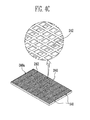
- FIG. 6A is a perspective view of a pattern structure of a bottom plate of a battery module according to another embodiment of the present invention.
- FIG. 6B is a perspective view of a pattern structure of a bottom plate of a battery module according to another embodiment of the present invention.
- FIG. 6C is a perspective view of a pattern structure of a bottom plate of a battery module according to another embodiment of the present invention.
- FIG. 1 is a perspective view of a battery module according to an embodiment of the present invention.
- FIG. 2 is a partially exploded perspective view of the battery module of FIG. 1 .
- a battery module 100 includes a plurality of battery cells 10 aligned in one direction; first and second end plates 110 and 120 respectively disposed at outsides of the battery cells 10; and a bottom plate 140 that supports bottom surfaces of the battery cells 10 and has at least a portion having a pattern structure (e.g., a repetitive pattern structure).
- a pattern structure e.g., a repetitive pattern structure
- Each battery cell 10 may be manufactured by accommodating an electrode assembly and an electrolyte in a battery case and then sealing the battery case with a cap plate 14.
- the cap plate 14 includes positive and negative electrode terminals 11 and 12 at respective ends on the cap plate 14, and a vent 13 between the positive and negative electrode terminals 11 and 12.
- the electrode assembly is composed of a positive electrode plate, a negative electrode plate, and a separator interposed between the positive and negative electrode plates.
- the positive electrode plate is connected to the positive electrode terminal 11, and the negative electrode plate is connected to the negative electrode terminal 12.
- Energy generated by an electrochemical reaction between the electrode assembly and the electrolyte is transferred to the outside of the battery cell 10 via the positive and negative electrode terminals 11 and 12.
- the vent 13 serves as a path through which gas generated inside the battery cell 10 may be exhausted to the outside of the battery cell 10.
- the pair of the first and second end plates 110 and 120 and the bottom plate 140 provide a space for accommodating the plurality of battery cells 10.
- the battery cells 10 may be fixed in the space defined by the first and second end plates 110 and 120 and the bottom plate 140 by being accommodated in the space and aligned in one direction. In this embodiment, the battery cells 10 are aligned in parallel such that wide lateral surfaces (e.g., front and rear surfaces) of the battery cells 10 are opposite one another.
- the positive and negative electrode terminals 11 and 12 of adjacent battery cells 10 are electrically connected to each other through bus bars 15.
- Each bus bar 15 is provided with holes through which the positive and negative electrode terminals 11 and 12 penetrate, respectively.
- the bus bar 15 and the positive and negative electrode terminals 11 and 12 connected thereto may be fixed together by members such as nuts 16.
- the first and second end plates 110 and 120 are disposed to contact outer surfaces of the outermost battery cells 10, respectively.
- the first and second end plates 110 and 120 apply pressure in an inward direction to the plurality of battery cells 10.
- the plurality of battery cells 10 supported by the first and second end plates 110 and 120 and the bottom plate 140 may be connected in series to one another by alternately aligning the positive and negative electrode terminals 11 and 12.
- the first and second end plates 110 and 120 are provided with first fastening holes 111 and 121 respectively formed at portions of the first and second end plates 110 and 120 that come in contact with respective ends of the bottom plate 140. Further, the bottom plate 140 is provided with second fastening holes 141 respectively formed at portions of the bottom plate 140 corresponding to the first fastening holes 111 and 121 of the first and second end plates 110 and 120.
- the first and second fastening holes 111, 121, and 141 are penetrated by fastening members 20 for fastening the first and second end plates 110 and 120 to the bottom plate 140. That is, the first fastening holes 111 and 121, and the second fastening holes 141 respectively provided corresponding to the first fastening holes 111 and 112 are extended to each other, and the fastening members 20 penetrate the first and second fastening holes 111, 121, and 141 for connecting the bottom plate 140 to the first and second end plates 110 and 120.
- the fastening member 20 may include a bolt, a stud, or any other suitable threaded member or other fastening member.
- the fastening through the first and second fastening holes 111, 121, and 141 provides a simplified external appearance of the battery module 100 and also decreases the overall size of the battery module 100. Further, the first and second fastening holes 111, 121, and 141 effectively disperse stress generated by the plurality of battery cells 10, which is concentrated on the bottom plate 140, thereby improving the safety of the battery module 100.
- the battery module 100 further includes connecting members 130 in the form of side plates that respectively support one or both side surfaces of the battery cells 10.
- the plurality of battery cells 10 may be configured as the battery module 100 together with the first and second end plates 110 and 120 and the bottom plate 140, and the connecting member 130 may be absent.
- the battery module 100 further includes the connecting member 130 connecting the first and second end plates 110 and 120 to each other, such that the plurality of battery cells 10 may be more firmly fixed.
- the shape and/or number of plates of the housing may be variously modified according to a design of the battery module 100. That is, a housing of the battery module of the present invention is not limited to the configuration of the embodiment shown in FIGS. 1 and 2 .
- FIG. 3A is a partially exploded perspective view showing some components, including the end plates 110 and 120 and the bottom plate 140, of the battery module 100.
- FIG. 3B is a bottom perspective view of the bottom plate 140.
- the bottom plate 140 supports the bottom surfaces of the battery cells 10 via a top surface 144.
- the bottom plate 140 further includes a plurality of openings 142 arranged in a repetitive pattern on its bottom surface, Alternative patterns may be employed in other embodiments.
- the bottom of the bottom plate 140 is also provided with a contoured pattern that, in this particular embodiment, has a waffle configuration. Consequently, the pattern structure 140a includes recessed portions A (e.g., concave portions) and intermediate protruding portions B (e.g., pillar portions) surrounding outer circumferences of the recessed portions A.
- the openings 142 are each located in a respective one of the recessed portions A of the pattern structure 140a.
- the recessed portions A are portions having a thickness that is thinner than that of the protruding portions B.
- the opening 142 provided in the recessed portion A rather than the protruding portion B facilitates the moldability of the bottom plate 140, thereby improving productivity of the battery module 100.
- the pattern configuration is not limited to the waffle configuration of this embodiment.
- other honeycomb-like patterns may be used, along with a wide variety of regular and irregular arrays and matrixes.
- the battery module 100 further includes barriers 150 (see FIG. 2 ) respectively interposed between adjacent battery cells 10 of the plurality of battery cells 10. At least one of the openings 142 is provided at a location in the bottom plate 140 corresponding to a position of the barrier 150.
- the battery cell 10 may generate heat in a charging/discharging process thereof, and the generation of heat may cause deterioration of the battery cell 10. Particularly, in a case where the battery cell 10 is a high-capacity battery cell, the generation of heat may be problematic to the safety of the battery cell 10, and, therefore, it is desirable to control the generation of heat. Accordingly, in this embodiment, the barriers 150 are interposed between the respective neighboring battery cells 10 such that a space may be provided between the neighboring battery cells 10. The space may serve as a path for dissipating heat or a path for coolant for exchanging heat with the battery cells 10 such that the heat generated in the battery cells 10 is not accumulated.
- the openings 142 are provided in the bottom plate 140.
- the openings 142 may serve as a path for a coolant, and the coolant flowed through the openings 142 may exchange heat with the battery cells 10, thereby improving the performance of the battery module 100.
- the openings 142 are provided at positions corresponding to the barriers 150.
- the bottom plate 140 of the battery module 100 may be manufactured using a material with a high strength, such as steel, so as to support the weight of the plurality of battery cells 10.
- steel or the like may be heavy due to the characteristic of the material itself. Further, using steel or the like, it may be difficult to manufacture a battery module having a desired shape, and therefore, the production cost of the battery module may be increased.
- the material of the bottom plate 140 may include a plastic material (e.g., a thermoplastic), for example.
- the bottom plate 140 includes the pattern structure 140a, and accordingly, high strength is provided to compensate for a low strength of a plastic material or the like due to the characteristic of the material itself.
- the pattern structure 140a is a repetitive pattern structure, such as the honeycomb structure and the like, it can be made structurally strong, such that the pattern structure 140a reinforces the strength of a light weight material or a material having low strength. Therefore, the bottom plate 140 including the pattern structure 140a can have strength sufficient to support the weight of the battery cells 10 without using a high-strength material such as steel.
- the pattern structure 140a in this embodiment is provided on a surface opposite to the top surface 144 of the bottom plate 140 which supports the battery cells 10. That is, the pattern structure 140a is provided on a bottom surface of the bottom plate 140, as shown in FIG. 3B .
- a pattern structure may be provided on the top surface 144 of the bottom plate 140; however, an assembly material or a component may be inserted into the pattern structure on the top surface 144 and may require an additional process for removing the assembly material. Therefore the pattern structure 140a is provided to an outer surface of the bottom plate 140, i.e. a bottom surface of the battery module 100 to avoid such a problem and to obtain the high strength and light weight of the battery module 100 having the pattern structure 140a.
- FIGS. 4A through 6C Battery modules according to other embodiments of the present invention are described below with reference to FIGS. 4A through 6C .
- FIGS. 4A through 6C description of components and features of the battery modules which are the same or similar to those of the battery module 100 described above will not be repeated.
- FIG. 4A is a perspective view of a battery module 200 according to another embodiment of the present invention.
- FIG. 4B is a partially exploded perspective view showing some components, including end plates and a bottom plate, of the battery module 200.
- FIG. 4C is a bottom perspective view of the bottom plate of the battery module 200.
- the battery module 200 includes a plurality of battery cells 10 aligned in one direction; first and second end plates 210 and 220 respectively disposed at outsides of the battery cells 10; and a bottom plate 240 that supports bottom surfaces of the battery cells 10 and has at least a portion formed into a pattern structure 240a.
- the bottom plate 240 includes a base portion 244 disposed to support the bottom surfaces of the battery cells 10, and a respective flange portion 243 extending at an angle (e.g., bent at an angle) from each side of the base portion 244 to support side surfaces of the battery cells 10.
- the base portion 244 is provided to come in contact with lower portions (e.g., bottom corners) of the first and second end plates 210 and 220 such that the base portion 244 may support the plurality of battery cells 10.
- the pattern structure 240a is provided on a surface opposite to the top surface of the base portion 244 which supports the battery cells 10. That is, the pattern structure 240a is provided on a bottom surface of the base portion 244, as shown in FIG. 4C .
- the pattern structure 240a may have a similar configuration to the pattern structure 140a described above.
- the pattern structure 240a includes recessed portions A (e.g., concave portions) provided on a bottom surface of the base portion 244 and protruding portions B (e.g., pillar portions) surrounding the outer circumferences of the recessed portions A.
- the bottom plate 240 has a plurality of openings 242, and the openings 242 are respectively provided in the recessed portions A of the pattern structure 240a. Because of the characteristic of the pattern structure 240a, the battery module 200 may have light weight and high strength.
- Each flange portion 243 is bent approximately perpendicular to the base portion 244.
- the flange portions 243 include first and second flange portions 243a and 243b respectively provided at opposite sides of the base portion 244.
- the first and second flange portions 243a and 243b extend between the first and second end plates 210 and 220 so as to overlap at least a portion of the side surfaces of the battery cells 10.
- a distance "b" (see FIG. 4B ) between the first and second flange portions 243a and 243b corresponds to a width "a" of a wide surface (e.g., a front face) of the battery cells 10.
- the bottom plate 240 surrounds the bottom surfaces and portions of both the side surfaces of the battery cells 10 mounted on the bottom plate 240. That is, the first and second flange portions 243a and 243b are provided to surround both the side surfaces of the battery cells 10, such that a process of aligning the battery cells 10 can be easily performed.
- the first and second flange portions 243a and 243b constrain side portions of the plurality of battery cells 10 such that it is possible to prevent or substantially prevent the battery cells 10 from being separated in a direction of the battery module 200.
- a connecting member such as the connecting member 130 described above, may be absent and the weight of the battery module 200 may be decreased.
- FIG. 5A is a partially exploded perspective view showing some components, including end plates and a bottom plate, of a battery module according to another embodiment of the present invention.
- FIG. 5B is a bottom perspective view of the bottom plate shown in FIG. 5A .
- the battery module includes a bottom plate 340 and first and second end plates 310 and 320 respectively disposed at outsides of battery cells 10.
- the bottom plate 340 supports bottom surfaces of the battery cells 10 and has at least a portion formed into a pattern structure 340a.
- the bottom plate 340 includes a base portion 344 supporting the bottom surfaces of the battery cells 10, and flange portions 343 extending at an angle (e.g., bent upward) from either side of the base portion 344.
- the pattern structure 340a has a similar configuration to the pattern structure 140a described above. That is the pattern structure 340a includes one or more recessed portions A (e.g., concave portions) provided on a bottom surface of the base portion 344 and protruding portions B (e.g., pillar portions) surrounding this outer circumferences of the recessed portions A. Further, in this embodiment, the bottom plate 340 has openings 342, and the openings 342 are provided in respective ones of the recessed portions A of the pattern structure 340a. Because of the characteristic of the pattern structure 340a, the battery module may have light weight and high strength.
- the pattern structure 340a includes one or more recessed portions A (e.g., concave portions) provided on a bottom surface of the base portion 344 and protruding portions B (e.g., pillar portions) surrounding this outer circumferences of the recessed portions A.
- the bottom plate 340 has openings 342, and the openings 342 are provided in respective ones of the recessed portions A of the pattern
- the bottom plate 340 includes guide portions 345 provided to correspond to the battery cells 10 on a surface of the bottom plate 340 which faces or contacts the battery cells 10, so as to guide the positions of the battery cells 10. That is, the guide portions 345 are provided on at least one of the base portion 344 and the flange portions 343. (Although it is shown in FIG. 5 that the guide portions 345 are provided only on the flange portion 343, the present invention is not limited thereto).
- the guide portions 345 may be provided to protrude from at least one surface of the bottom plate 340 which faces or contacts the battery cells 10.
- the guide portions 345 may be provided to correspond to the external shape of the battery cell 10 mounted on the bottom plate 340.
- the guide portions 345 may guide the mounting positions of the battery cells 10. Thus, alignment of the plurality of the battery cells 10 may be facilitated, thereby improving the production efficiency of the battery module.
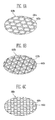
- FIGS. 6A to 6C are perspective views of pattern structures of a bottom plate according to other embodiments of the present invention.
- a pattern structure provided on a bottom plate of a battery module may be formed in at least one of a hexagonal shape, a triangular shape, and a circular shape, in addition to a square or rectangular shape.
- the present invention is not limited thereto and, in other embodiments, a bottom plate of a battery module may have a pattern structure including any other suitable shape or combination of shapes of openings, recesses, and/or protruding portions.
- the illustrated pattern structure 440a includes a honeycomb pattern (e.g., a repetitive pattern) of hexagonal recessed portions 441 a (e.g., concave portions) and protruding portions 442a (e.g., pillar portions) provided around outer circumferences of the hexagonal recessed portions 441 a.
- a honeycomb pattern e.g., a repetitive pattern
- hexagonal recessed portions 441 a e.g., concave portions
- protruding portions 442a e.g., pillar portions
- the illustrated pattern structure 440b includes a pattern (e.g., a repetitive pattern) of triangular recessed portions 441b (e.g., concave portions) and protruding portions 442b (e.g., pillar portions) provided around outer circumferences of the triangular recessed portions 441 b.
- a pattern e.g., a repetitive pattern
- triangular recessed portions 441b e.g., concave portions
- protruding portions 442b e.g., pillar portions
- the illustrated pattern structure 440c includes a pattern (e.g., a repetitive pattern) of circular recessed portions 441 c (e.g., concave portions) and protruding portions 442c (e.g., pillar portions) provided around outer circumferences of the circular recessed portions 441 c.
- a pattern e.g., a repetitive pattern
- circular recessed portions 441 c e.g., concave portions
- protruding portions 442c e.g., pillar portions
- the pattern structure 440a, 440b, or 440c provided on the bottom plate can maintain the light weight and high strength of a bottom plate of a battery module according to embodiments of the present invention.
- a bottom plate of a battery module having one of the pattern structures 440a, 440b, or 440c may have one or more openings (not shown), similar to the openings 142 described above, provided in one or more of the recessed portions of the pattern structure 440a, 440b, or 440c.
- the pattern structure 440a, 440b, or 440c may be provided at a portion exposed on an outer surface of the battery module, and the external appearance of the battery module may be influenced by the pattern structure 440a, 440b, or 440c.
- the pattern structures 440a, 440b, and 440c enable the design of the battery module to be variously implemented.
- a battery module according to the present invention includes a novel plate member, thereby decreasing the size and/or weight of the battery module.
- battery modules according to embodiments of the present invention are particularly applicable as a motor-driving power source for propelling hybrid vehicles or electric vehicles. Further, a battery module according to embodiments of the present invention has improved productivity due to a manufacturing process thereof.
Abstract
Description
- The present invention relates to a battery module.
- A high-power battery module using a non-aqueous electrolyte with high energy density has recently been developed. The high-power battery module is configured as a large-capacity battery module manufactured by connecting a plurality of battery cells in series such that it may be used in driving motors of devices requiring high power, such as hybrid vehicles, electric vehicles, and the like.
- A battery cell includes an electrolyte and an electrode assembly composed of a positive electrode plate and a negative electrode plate, and generates energy through an electrochemical reaction of the positive and negative electrode plates and the electrolyte. In this instance, gas may be generated as a side reaction of the electrochemical reaction in the interior of the battery cell. The generated gas may change the external shape of the battery cell. Further, the change in the external shape of the battery cell may affect the shape of a battery module formed by aligning a plurality of battery cells, and may result in the battery cells not being firmly fixed in the battery module. Battery modules having various shapes have been developed so as to reduce the change in the external shape of the battery cells and to improve productivity of the battery modules. These often include structures for maintaining the shape and relative positions of the battery cells, but such structures can add weight and bulk to the battery module, which is generally undesirable.
- The present invention sets out to provide a battery module having reduced size and/or weight. As such, battery modules according to embodiments of the present invention can be particularly applicable as a motor-driving power source for propelling hybrid vehicles or electric vehicles.
- The present invention also sets out to provide a battery module having improved productivity due to a manufacturing process thereof.
- According to an embodiment of the present invention, a battery module includes: a plurality of battery cells aligned in a direction; first and second end plates respectively arranged at outer sides of the plurality of battery cells; and a bottom plate supporting bottom surfaces of the battery cells and including at least a portion including a pattern structure.
- The bottom plate may include a plastic material.
- The pattern structure may include a honeycomb structure.
- The pattern structure may include at least one recessed portion on a bottom surface of the bottom plate, and a protruding portion surrounding an outer circumference of the at least one recessed portion.
- The bottom plate may have at least one opening formed therethrough. The at least one opening may be formed through the at least one recessed portion of the pattern structure.
- The battery module may further include a barrier between adjacent battery cells of the plurality of battery cells, wherein the at least one opening is at a location corresponding to the barrier.
- The bottom plate may include a base portion facing the bottom surfaces of the battery cells, and at least one flange portion extending at an angle from at least one side of the base portion and facing side surfaces of the battery cells.
- In one embodiment, the at least one flange portion includes first and second flange portions respectively extending from opposite sides of the base portion, and the first and second flange portions extend between the first and second end plates and overlap at least portions of the side surfaces of the battery cells.
- The pattern structure may be formed on a second surface of the base portion opposite a first surface of the base portion which faces the bottom surfaces of the battery cells.
- The pattern structure may include recesses having at least one of a hexagonal shape, a triangular shape, a rectangular shape, or a circular shape.
- The pattern structure may include a repetitive pattern structure.
- In one embodiment, the bottom plate includes a guide portion at a location corresponding to a position of a battery cell of the plurality of battery cells, and the guide portion faces the battery cell to guide the battery cell into the position.
- In one embodiment, at least one of the first and second end plates has a first fastening hole at a portion that contacts an end of the bottom plate, and the bottom plate has a second fastening hole at a location corresponding to the first fastening hole.
- The battery module may further include fastening members in the first and second fastening holes and fastening the first and second end plates to the bottom plate.
- The fastening members may include bolts or studs.
- The battery module may further include a connecting member connecting the first and second end plates to each other.
- The connecting member may include side plates respectively supporting opposite side surfaces of the battery cells.
- According to aspects of embodiments of the present invention, a battery module is lightweight and includes a novel plate member.
- Also, according to another aspect of embodiments of the present invention, productivity of a battery module is increased due to an improved manufacturing process thereof.
- At least some of the above and other features of the invention are set out in the Claims.
- The accompanying drawings illustrate some embodiments of the present invention, and, together with the description, serve to explain principles of the present invention.
-
FIG. 1 is a perspective view of a battery module according to an embodiment of the present invention. -
FIG. 2 is a partially exploded perspective view of the battery module ofFIG. 1 . -
FIG. 3A is a partially exploded perspective view of some components of the battery module ofFIG. 1 . -
FIG. 3B is a bottom perspective view of a bottom plate of the battery module ofFIG. 1 . -
FIG. 4A is a perspective view of a battery module according to another embodiment of the present invention. -
FIG. 4B is a partially exploded perspective view of some components of the battery module ofFIG. 4A . -
FIG. 4C is a bottom perspective view of a bottom plate of the battery module ofFIG. 4A . -
FIG. 5A is partially exploded perspective view of some components of a battery module according to another embodiment of the present invention. -
FIG. 5B is a bottom perspective view of a bottom plate of the battery module ofFIG. 5A , -
FIG. 6A is a perspective view of a pattern structure of a bottom plate of a battery module according to another embodiment of the present invention. -
FIG. 6B is a perspective view of a pattern structure of a bottom plate of a battery module according to another embodiment of the present invention. -
FIG. 6C is a perspective view of a pattern structure of a bottom plate of a battery module according to another embodiment of the present invention. - In the following detailed description, some embodiments of the present invention are shown and described, by way of illustration. As those skilled in the art would realize, the described embodiments may be modified in various different ways, all without departing from the scope of the present invention. Accordingly, the drawings and description are to be regarded as illustrative in nature and not restrictive. In addition, when an element is referred to as being "on" another element, it can be directly on the another element or be indirectly on the another element with one or more intervening elements interposed therebetween. Also, when an element is referred to as being "connected to" another element, it can be directly connected to the another element or be indirectly connected to the another element with one or more intervening elements interposed therebetween. Hereinafter, like reference numerals refer to like elements.
-
FIG. 1 is a perspective view of a battery module according to an embodiment of the present invention.FIG. 2 is a partially exploded perspective view of the battery module ofFIG. 1 . - Referring to
FIGS. 1 and2 , abattery module 100 according to an embodiment of the present invention includes a plurality ofbattery cells 10 aligned in one direction; first andsecond end plates battery cells 10; and abottom plate 140 that supports bottom surfaces of thebattery cells 10 and has at least a portion having a pattern structure (e.g., a repetitive pattern structure). - Each
battery cell 10 may be manufactured by accommodating an electrode assembly and an electrolyte in a battery case and then sealing the battery case with acap plate 14. Thecap plate 14 includes positive andnegative electrode terminals cap plate 14, and avent 13 between the positive andnegative electrode terminals positive electrode terminal 11, and the negative electrode plate is connected to thenegative electrode terminal 12. Energy generated by an electrochemical reaction between the electrode assembly and the electrolyte is transferred to the outside of thebattery cell 10 via the positive andnegative electrode terminals vent 13 serves as a path through which gas generated inside thebattery cell 10 may be exhausted to the outside of thebattery cell 10. - The pair of the first and
second end plates bottom plate 140 provide a space for accommodating the plurality ofbattery cells 10. Thebattery cells 10 may be fixed in the space defined by the first andsecond end plates bottom plate 140 by being accommodated in the space and aligned in one direction. In this embodiment, thebattery cells 10 are aligned in parallel such that wide lateral surfaces (e.g., front and rear surfaces) of thebattery cells 10 are opposite one another. The positive andnegative electrode terminals adjacent battery cells 10 are electrically connected to each other through bus bars 15. Eachbus bar 15 is provided with holes through which the positive andnegative electrode terminals bus bar 15 and the positive andnegative electrode terminals - The first and
second end plates outermost battery cells 10, respectively. Thus, in this embodiment, the first andsecond end plates battery cells 10. The plurality ofbattery cells 10 supported by the first andsecond end plates bottom plate 140 may be connected in series to one another by alternately aligning the positive andnegative electrode terminals - The first and
second end plates second end plates bottom plate 140. Further, thebottom plate 140 is provided with second fastening holes 141 respectively formed at portions of thebottom plate 140 corresponding to the first fastening holes 111 and 121 of the first andsecond end plates - The first and second fastening holes 111, 121, and 141 are penetrated by fastening
members 20 for fastening the first andsecond end plates bottom plate 140. That is, the first fastening holes 111 and 121, and the second fastening holes 141 respectively provided corresponding to the first fastening holes 111 and 112 are extended to each other, and thefastening members 20 penetrate the first and second fastening holes 111, 121, and 141 for connecting thebottom plate 140 to the first andsecond end plates fastening member 20 may include a bolt, a stud, or any other suitable threaded member or other fastening member. - The fastening through the first and second fastening holes 111, 121, and 141 provides a simplified external appearance of the
battery module 100 and also decreases the overall size of thebattery module 100. Further, the first and second fastening holes 111, 121, and 141 effectively disperse stress generated by the plurality ofbattery cells 10, which is concentrated on thebottom plate 140, thereby improving the safety of thebattery module 100. - The
battery module 100 further includes connectingmembers 130 in the form of side plates that respectively support one or both side surfaces of thebattery cells 10. In an alternative embodiment, the plurality ofbattery cells 10 may be configured as thebattery module 100 together with the first andsecond end plates bottom plate 140, and the connectingmember 130 may be absent. However, in this embodiment, thebattery module 100 further includes the connectingmember 130 connecting the first andsecond end plates battery cells 10 may be more firmly fixed. - The first and
second end plates bottom plate 140, and, where present, the connectingmember 130 including the side plates or the like, make up a housing for stably fixing the plurality ofbattery cells 10. The shape and/or number of plates of the housing may be variously modified according to a design of thebattery module 100. That is, a housing of the battery module of the present invention is not limited to the configuration of the embodiment shown inFIGS. 1 and2 . -
FIG. 3A is a partially exploded perspective view showing some components, including theend plates bottom plate 140, of thebattery module 100.FIG. 3B is a bottom perspective view of thebottom plate 140. - Referring to
FIGS. 3A and3B , in this embodiment, thebottom plate 140 supports the bottom surfaces of thebattery cells 10 via atop surface 144. Thebottom plate 140 further includes a plurality ofopenings 142 arranged in a repetitive pattern on its bottom surface, Alternative patterns may be employed in other embodiments. - The bottom of the
bottom plate 140 is also provided with a contured pattern that, in this particular embodiment, has a waffle configuration. Consequently, thepattern structure 140a includes recessed portions A (e.g., concave portions) and intermediate protruding portions B (e.g., pillar portions) surrounding outer circumferences of the recessed portions A. In this embodiment, theopenings 142 are each located in a respective one of the recessed portions A of thepattern structure 140a. The recessed portions A are portions having a thickness that is thinner than that of the protruding portions B. Thus, theopening 142 provided in the recessed portion A rather than the protruding portion B facilitates the moldability of thebottom plate 140, thereby improving productivity of thebattery module 100. - The pattern configuration is not limited to the waffle configuration of this embodiment. For example, other honeycomb-like patterns may be used, along with a wide variety of regular and irregular arrays and matrixes.
- The
battery module 100 further includes barriers 150 (seeFIG. 2 ) respectively interposed betweenadjacent battery cells 10 of the plurality ofbattery cells 10. At least one of theopenings 142 is provided at a location in thebottom plate 140 corresponding to a position of thebarrier 150. - The
battery cell 10 may generate heat in a charging/discharging process thereof, and the generation of heat may cause deterioration of thebattery cell 10. Particularly, in a case where thebattery cell 10 is a high-capacity battery cell, the generation of heat may be problematic to the safety of thebattery cell 10, and, therefore, it is desirable to control the generation of heat. Accordingly, in this embodiment, thebarriers 150 are interposed between the respective neighboringbattery cells 10 such that a space may be provided between the neighboringbattery cells 10. The space may serve as a path for dissipating heat or a path for coolant for exchanging heat with thebattery cells 10 such that the heat generated in thebattery cells 10 is not accumulated. - In the
battery module 100 according to this embodiment, theopenings 142 are provided in thebottom plate 140. Theopenings 142 may serve as a path for a coolant, and the coolant flowed through theopenings 142 may exchange heat with thebattery cells 10, thereby improving the performance of thebattery module 100. Accordingly, in this embodiment, theopenings 142 are provided at positions corresponding to thebarriers 150. - The
bottom plate 140 of thebattery module 100 may be manufactured using a material with a high strength, such as steel, so as to support the weight of the plurality ofbattery cells 10. However, steel or the like may be heavy due to the characteristic of the material itself. Further, using steel or the like, it may be difficult to manufacture a battery module having a desired shape, and therefore, the production cost of the battery module may be increased. - Therefore, according to an embodiment of the present invention, the material of the
bottom plate 140 may include a plastic material (e.g., a thermoplastic), for example. Thebottom plate 140 includes thepattern structure 140a, and accordingly, high strength is provided to compensate for a low strength of a plastic material or the like due to the characteristic of the material itself. - For example, wherein the
pattern structure 140a is a repetitive pattern structure, such as the honeycomb structure and the like, it can be made structurally strong, such that thepattern structure 140a reinforces the strength of a light weight material or a material having low strength. Therefore, thebottom plate 140 including thepattern structure 140a can have strength sufficient to support the weight of thebattery cells 10 without using a high-strength material such as steel. - The
pattern structure 140a in this embodiment is provided on a surface opposite to thetop surface 144 of thebottom plate 140 which supports thebattery cells 10. That is, thepattern structure 140a is provided on a bottom surface of thebottom plate 140, as shown inFIG. 3B . In another embodiment, a pattern structure may be provided on thetop surface 144 of thebottom plate 140; however, an assembly material or a component may be inserted into the pattern structure on thetop surface 144 and may require an additional process for removing the assembly material. Therefore thepattern structure 140a is provided to an outer surface of thebottom plate 140, i.e. a bottom surface of thebattery module 100 to avoid such a problem and to obtain the high strength and light weight of thebattery module 100 having thepattern structure 140a. - Battery modules according to other embodiments of the present invention are described below with reference to
FIGS. 4A through 6C . InFIGS. 4A through 6C , description of components and features of the battery modules which are the same or similar to those of thebattery module 100 described above will not be repeated. -
FIG. 4A is a perspective view of abattery module 200 according to another embodiment of the present invention.FIG. 4B is a partially exploded perspective view showing some components, including end plates and a bottom plate, of thebattery module 200.FIG. 4C is a bottom perspective view of the bottom plate of thebattery module 200. - Referring to
FIGS. 4A through 4C , thebattery module 200 according to this embodiment includes a plurality ofbattery cells 10 aligned in one direction; first andsecond end plates battery cells 10; and abottom plate 240 that supports bottom surfaces of thebattery cells 10 and has at least a portion formed into apattern structure 240a. - The
bottom plate 240 includes abase portion 244 disposed to support the bottom surfaces of thebattery cells 10, and arespective flange portion 243 extending at an angle (e.g., bent at an angle) from each side of thebase portion 244 to support side surfaces of thebattery cells 10. - The
base portion 244 is provided to come in contact with lower portions (e.g., bottom corners) of the first andsecond end plates base portion 244 may support the plurality ofbattery cells 10. Thepattern structure 240a is provided on a surface opposite to the top surface of thebase portion 244 which supports thebattery cells 10. That is, thepattern structure 240a is provided on a bottom surface of thebase portion 244, as shown inFIG. 4C . Thepattern structure 240a may have a similar configuration to thepattern structure 140a described above. That is, in this embodiment, thepattern structure 240a includes recessed portions A (e.g., concave portions) provided on a bottom surface of thebase portion 244 and protruding portions B (e.g., pillar portions) surrounding the outer circumferences of the recessed portions A. Further, in this embodiment, thebottom plate 240 has a plurality ofopenings 242, and theopenings 242 are respectively provided in the recessed portions A of thepattern structure 240a. Because of the characteristic of thepattern structure 240a, thebattery module 200 may have light weight and high strength. - Each
flange portion 243 is bent approximately perpendicular to thebase portion 244. Theflange portions 243 include first andsecond flange portions base portion 244. The first andsecond flange portions second end plates battery cells 10. - In this embodiment, a distance "b" (see
FIG. 4B ) between the first andsecond flange portions battery cells 10. Thus thebottom plate 240 surrounds the bottom surfaces and portions of both the side surfaces of thebattery cells 10 mounted on thebottom plate 240. That is, the first andsecond flange portions battery cells 10, such that a process of aligning thebattery cells 10 can be easily performed. Further, in this embodiment, the first andsecond flange portions battery cells 10 such that it is possible to prevent or substantially prevent thebattery cells 10 from being separated in a direction of thebattery module 200. Thus, in thebattery module 200, a connecting member, such as the connectingmember 130 described above, may be absent and the weight of thebattery module 200 may be decreased. -
FIG. 5A is a partially exploded perspective view showing some components, including end plates and a bottom plate, of a battery module according to another embodiment of the present invention.FIG. 5B is a bottom perspective view of the bottom plate shown inFIG. 5A . - Referring to
FIGS. 5A and5B , the battery module according to this embodiment of the present invention includes abottom plate 340 and first andsecond end plates battery cells 10. Thebottom plate 340 supports bottom surfaces of thebattery cells 10 and has at least a portion formed into apattern structure 340a. The bottom plate 340includes abase portion 344 supporting the bottom surfaces of thebattery cells 10, andflange portions 343 extending at an angle (e.g., bent upward) from either side of thebase portion 344. - The
pattern structure 340a has a similar configuration to thepattern structure 140a described above. That is thepattern structure 340a includes one or more recessed portions A (e.g., concave portions) provided on a bottom surface of thebase portion 344 and protruding portions B (e.g., pillar portions) surrounding this outer circumferences of the recessed portions A. Further, in this embodiment, thebottom plate 340 hasopenings 342, and theopenings 342 are provided in respective ones of the recessed portions A of thepattern structure 340a. Because of the characteristic of thepattern structure 340a, the battery module may have light weight and high strength. - In this embodiment, the
bottom plate 340 includesguide portions 345 provided to correspond to thebattery cells 10 on a surface of thebottom plate 340 which faces or contacts thebattery cells 10, so as to guide the positions of thebattery cells 10. That is, theguide portions 345 are provided on at least one of thebase portion 344 and theflange portions 343. (Although it is shown inFIG. 5 that theguide portions 345 are provided only on theflange portion 343, the present invention is not limited thereto). - The
guide portions 345 may be provided to protrude from at least one surface of thebottom plate 340 which faces or contacts thebattery cells 10. Theguide portions 345 may be provided to correspond to the external shape of thebattery cell 10 mounted on thebottom plate 340. In the process of manufacturing the battery module according to one embodiment, theguide portions 345 may guide the mounting positions of thebattery cells 10. Thus, alignment of the plurality of thebattery cells 10 may be facilitated, thereby improving the production efficiency of the battery module. -
FIGS. 6A to 6C are perspective views of pattern structures of a bottom plate according to other embodiments of the present invention. - Referring to
FIGS. 6A to 6C , according to other embodiments of the present invention, a pattern structure provided on a bottom plate of a battery module may be formed in at least one of a hexagonal shape, a triangular shape, and a circular shape, in addition to a square or rectangular shape. Further, the present invention is not limited thereto and, in other embodiments, a bottom plate of a battery module may have a pattern structure including any other suitable shape or combination of shapes of openings, recesses, and/or protruding portions. - With reference to
FIG. 6A , the illustratedpattern structure 440a includes a honeycomb pattern (e.g., a repetitive pattern) of hexagonal recessedportions 441 a (e.g., concave portions) and protrudingportions 442a (e.g., pillar portions) provided around outer circumferences of the hexagonal recessedportions 441 a. - With reference to
FIG. 6B , the illustratedpattern structure 440b includes a pattern (e.g., a repetitive pattern) of triangular recessedportions 441b (e.g., concave portions) and protrudingportions 442b (e.g., pillar portions) provided around outer circumferences of the triangular recessedportions 441 b. - With reference to
FIG. 6C , the illustratedpattern structure 440c includes a pattern (e.g., a repetitive pattern) of circular recessedportions 441 c (e.g., concave portions) and protrudingportions 442c (e.g., pillar portions) provided around outer circumferences of the circular recessedportions 441 c. - The
pattern structure pattern structures openings 142 described above, provided in one or more of the recessed portions of thepattern structure pattern structure pattern structure pattern structures - As described above, a battery module according to the present invention includes a novel plate member, thereby decreasing the size and/or weight of the battery module. As such, battery modules according to embodiments of the present invention are particularly applicable as a motor-driving power source for propelling hybrid vehicles or electric vehicles. Further, a battery module according to embodiments of the present invention has improved productivity due to a manufacturing process thereof.
- While the present invention has been described in connection with certain embodiments, it is to be understood that the invention is not limited to the disclosed embodiments, but, on the contrary, is intended to cover various modifications and equivalent arrangements included within the scope of the appended claims, and equivalents thereof.
Claims (15)
- A battery module comprising:a plurality of battery cells aligned in a first direction;first and second end plates respectively arranged at outer sides of the plurality of battery cells; anda bottom plate supporting bottom surfaces of the battery cells and comprising at least a portion thereof including a pattern structure.
- A battery module according to claim 1, wherein the bottom plate comprises a plastic material.
- The battery module according to claim 1, wherein the pattern structure comprises a honeycomb structure.
- A battery module according to claim 1, 2 or 3, wherein the pattern structure includes at least one recessed portion and a protruding portion surrounding an outer circumference of the at least one recessed portion.
- A battery module according to claim 4, wherein the pattern structure comprises an array of recessed portions in which the said recessed portions are separated by respective ones of a plurality of the said protruding portions.
- A battery module according to any preceding claim, wherein the bottom plate has at least one opening formed therethrough.
- A battery module according to claim 6 when dependent upon claims 3 or 4, wherein the at least one opening is formed through the at least one recessed portion of the pattern structure.
- A battery module according to claim 6 or 7, further comprising a barrier situated between adjacent ones of the plurality of battery cells, wherein the at least one opening is at a location corresponding to the barrier.
- A battery module according to any preceding claim, wherein the bottom plate comprises a base portion facing the bottom surfaces of the battery cells, and at least one flange portion extending at an angle from at least one side region of the base portion and facing side surfaces of the battery cells.
- A battery module according to claim 9,
wherein the at least one flange portion comprises first and second flange portions respectively extending from opposite sides of the base portion, and
wherein the first and second flange portions extend between the first and second end plates and overlap at least portions of the side surfaces of the battery cells. - A battery module according to any preceding claim, wherein the pattern structure is formed on a second surface of the bottom plate opposite a first surface of the bottom plate portion which faces the bottom surfaces of the battery cells.
- A battery module according to claim 3 or any claim dependent thereon, wherein the or each recess has a hexagonal shape, a triangular shape, a rectangular shape, or a circular shape.
- A battery module according to any preceding claim,
wherein the bottom plate comprises a guide portion at a location corresponding to a position of a battery cell of the plurality of battery cells, and
wherein the guide portion faces the battery cell so as to guide the battery cell into the position. - A battery module according to any preceding claim,
wherein at least one of the first and second end plates has a first fastening hole at a portion that contacts an end of the bottom plate, and
wherein the bottom plate has a second fastening hole at a location corresponding to the first fastening hole. - A battery module according to claim 14, further comprising fastening members in the first and second fastening holes that fasten the first and second end plates to the bottom plate.
Applications Claiming Priority (1)
| Application Number | Priority Date | Filing Date | Title |
|---|---|---|---|
| KR1020110037305A KR101252935B1 (en) | 2011-04-21 | 2011-04-21 | Battery module |
Publications (2)
| Publication Number | Publication Date |
|---|---|
| EP2515360A1 true EP2515360A1 (en) | 2012-10-24 |
| EP2515360B1 EP2515360B1 (en) | 2019-03-06 |
Family
ID=45065760
Family Applications (1)
| Application Number | Title | Priority Date | Filing Date |
|---|---|---|---|
| EP11190419.9A Active EP2515360B1 (en) | 2011-04-21 | 2011-11-23 | Battery module |
Country Status (3)
| Country | Link |
|---|---|
| US (1) | US8999545B2 (en) |
| EP (1) | EP2515360B1 (en) |
| KR (1) | KR101252935B1 (en) |
Cited By (3)
| Publication number | Priority date | Publication date | Assignee | Title |
|---|---|---|---|---|
| EP2843729A1 (en) * | 2013-08-28 | 2015-03-04 | Samsung SDI Co., Ltd. | Battery module |
| WO2016026678A1 (en) * | 2014-08-19 | 2016-02-25 | Robert Bosch Gmbh | Receptacle for a battery module, and battery module having a receptacle of this kind |
| CN112332007A (en) * | 2019-09-27 | 2021-02-05 | 宁德时代新能源科技股份有限公司 | Battery module, battery pack, vehicle, and method for assembling battery module |
Families Citing this family (11)
| Publication number | Priority date | Publication date | Assignee | Title |
|---|---|---|---|---|
| KR101252952B1 (en) * | 2011-05-02 | 2013-04-15 | 로베르트 보쉬 게엠베하 | Battery module for preventing movement of battery cell |
| KR102122926B1 (en) * | 2012-12-05 | 2020-06-15 | 에스케이이노베이션 주식회사 | Battery Sub-Pack and a Method for manufacturing the same |
| CN105324866B (en) * | 2013-07-26 | 2017-12-19 | 新日铁住金株式会社 | Battery pack stacker and battery pack |
| JP5929871B2 (en) * | 2013-10-17 | 2016-06-08 | トヨタ自動車株式会社 | Method for molding thermoplastic resin material |
| KR102172433B1 (en) * | 2014-03-26 | 2020-10-30 | 에스케이이노베이션 주식회사 | Water cooling device for Battery module and Battery Pack having the device |
| JP6355956B2 (en) * | 2014-04-16 | 2018-07-11 | 矢崎エナジーシステム株式会社 | Battery pack and power supply |
| US9608245B2 (en) | 2014-09-30 | 2017-03-28 | Johnson Controls Technology Company | System for providing structural integrity of a battery module |
| US9887401B2 (en) * | 2015-08-21 | 2018-02-06 | The Boeing Company | Battery assembly, battery containment apparatus, and related methods of manufacture |
| TWI597880B (en) * | 2016-03-07 | 2017-09-01 | 輝能科技股份有限公司 | Flexible package |
| KR102372348B1 (en) | 2018-06-08 | 2022-03-07 | 주식회사 엘지에너지솔루션 | Battery module with improved cooling structure |
| US11936058B2 (en) * | 2018-11-13 | 2024-03-19 | Rivian Ip Holdings, Llc | Electric vehicle battery pack having bottom strike shield |
Citations (5)
| Publication number | Priority date | Publication date | Assignee | Title |
|---|---|---|---|---|
| US5585204A (en) * | 1993-12-27 | 1996-12-17 | Honda Giken Kogyo Kabushiki Kaisha | Temperature control structure for batteries and battery box for housing such batteries |
| JP2002026748A (en) * | 2000-07-07 | 2002-01-25 | Tookado:Kk | Structure of battery case |
| US20020015880A1 (en) * | 2000-06-19 | 2002-02-07 | C&D Technologies, Inc. | Molded modular lead-acid battery system |
| EP1610407A1 (en) * | 2004-06-25 | 2005-12-28 | Samsung SDI Co., Ltd. | Secondary battery module |
| JP2007299544A (en) * | 2006-04-27 | 2007-11-15 | Sanyo Electric Co Ltd | Battery pack |
Family Cites Families (13)
| Publication number | Priority date | Publication date | Assignee | Title |
|---|---|---|---|---|
| US5620057A (en) | 1994-12-19 | 1997-04-15 | General Motors Corporation | Electric vehicle battery enclosure |
| US6183903B1 (en) * | 1998-02-03 | 2001-02-06 | Gnb Technologies, Inc. | Plastic battery container having reduced end wall deflection |
| US6586132B1 (en) * | 1999-03-03 | 2003-07-01 | Matsushita Electric Industrial Co., Ltd. | Sealed battery pack |
| JP4742514B2 (en) * | 2004-04-14 | 2011-08-10 | トヨタ自動車株式会社 | Battery pack and its casing |
| US7989104B2 (en) * | 2004-10-28 | 2011-08-02 | Samsung Sdi Co., Ltd. | Battery module |
| KR100669414B1 (en) * | 2004-11-30 | 2007-01-15 | 삼성에스디아이 주식회사 | Secondary battery module and wall of secondary battery module |
| WO2008074034A1 (en) * | 2006-12-14 | 2008-06-19 | Johnson Controls - Saft Advanced Power Solutions Llc | Battery module |
| JP5082568B2 (en) | 2007-04-26 | 2012-11-28 | トヨタ自動車株式会社 | Power storage device |
| KR101104151B1 (en) * | 2007-06-28 | 2012-01-13 | 주식회사 엘지화학 | Device Having Plate-typed Reinforcement Member |
| JP4775436B2 (en) | 2008-02-29 | 2011-09-21 | 日産自動車株式会社 | Battery module and battery module manufacturing method |
| US8216502B2 (en) * | 2008-12-02 | 2012-07-10 | Tesla Motors, Inc. | Method for the external application of battery pack encapsulant |
| KR101050315B1 (en) * | 2009-02-26 | 2011-07-19 | 에스비리모티브 주식회사 | Secondary battery module |
| JP5518386B2 (en) * | 2009-07-17 | 2014-06-11 | 三洋電機株式会社 | Battery system |
-
2011
- 2011-04-21 KR KR1020110037305A patent/KR101252935B1/en active IP Right Grant
- 2011-07-20 US US13/187,377 patent/US8999545B2/en active Active
- 2011-11-23 EP EP11190419.9A patent/EP2515360B1/en active Active
Patent Citations (5)
| Publication number | Priority date | Publication date | Assignee | Title |
|---|---|---|---|---|
| US5585204A (en) * | 1993-12-27 | 1996-12-17 | Honda Giken Kogyo Kabushiki Kaisha | Temperature control structure for batteries and battery box for housing such batteries |
| US20020015880A1 (en) * | 2000-06-19 | 2002-02-07 | C&D Technologies, Inc. | Molded modular lead-acid battery system |
| JP2002026748A (en) * | 2000-07-07 | 2002-01-25 | Tookado:Kk | Structure of battery case |
| EP1610407A1 (en) * | 2004-06-25 | 2005-12-28 | Samsung SDI Co., Ltd. | Secondary battery module |
| JP2007299544A (en) * | 2006-04-27 | 2007-11-15 | Sanyo Electric Co Ltd | Battery pack |
Cited By (5)
| Publication number | Priority date | Publication date | Assignee | Title |
|---|---|---|---|---|
| EP2843729A1 (en) * | 2013-08-28 | 2015-03-04 | Samsung SDI Co., Ltd. | Battery module |
| WO2016026678A1 (en) * | 2014-08-19 | 2016-02-25 | Robert Bosch Gmbh | Receptacle for a battery module, and battery module having a receptacle of this kind |
| CN106575728A (en) * | 2014-08-19 | 2017-04-19 | 罗伯特·博世有限公司 | Receptacle for a battery module, and battery module having a receptacle of this kind |
| CN112332007A (en) * | 2019-09-27 | 2021-02-05 | 宁德时代新能源科技股份有限公司 | Battery module, battery pack, vehicle, and method for assembling battery module |
| CN112332007B (en) * | 2019-09-27 | 2022-02-01 | 宁德时代新能源科技股份有限公司 | Battery module, battery pack, vehicle, and method for assembling battery module |
Also Published As
| Publication number | Publication date |
|---|---|
| EP2515360B1 (en) | 2019-03-06 |
| KR101252935B1 (en) | 2013-04-09 |
| US20120270095A1 (en) | 2012-10-25 |
| US8999545B2 (en) | 2015-04-07 |
| KR20120119405A (en) | 2012-10-31 |
Similar Documents
| Publication | Publication Date | Title |
|---|---|---|
| EP2515360B1 (en) | Battery module | |
| US8734979B2 (en) | Battery module | |
| US9570721B2 (en) | Battery module | |
| JP6088185B2 (en) | Battery module | |
| US10062879B2 (en) | Battery module assembly of improved reliability and battery pack employed with the same | |
| US8771864B2 (en) | Battery module | |
| US8512889B1 (en) | Battery module | |
| US9166260B2 (en) | Battery module | |
| US9406916B2 (en) | Battery module | |
| US20140356684A1 (en) | Battery module | |
| US9012063B2 (en) | Battery module | |
| US9419262B2 (en) | Battery module | |
| US20130052514A1 (en) | Battery cell and battery module using the same | |
| US8956752B2 (en) | Battery module | |
| US8623535B2 (en) | Battery module | |
| EP2450979B1 (en) | Battery module |
Legal Events
| Date | Code | Title | Description |
|---|---|---|---|
| PUAI | Public reference made under article 153(3) epc to a published international application that has entered the european phase |
Free format text: ORIGINAL CODE: 0009012 |
|
| 17P | Request for examination filed |
Effective date: 20120329 |
|
| AK | Designated contracting states |
Kind code of ref document: A1 Designated state(s): AL AT BE BG CH CY CZ DE DK EE ES FI FR GB GR HR HU IE IS IT LI LT LU LV MC MK MT NL NO PL PT RO RS SE SI SK SM TR |
|
| AX | Request for extension of the european patent |
Extension state: BA ME |
|
| RAP1 | Party data changed (applicant data changed or rights of an application transferred) |
Owner name: SAMSUNG SDI CO., LTD. Owner name: ROBERT BOSCH GMBH |
|
| 17Q | First examination report despatched |
Effective date: 20141024 |
|
| STAA | Information on the status of an ep patent application or granted ep patent |
Free format text: STATUS: EXAMINATION IS IN PROGRESS |
|
| RIC1 | Information provided on ipc code assigned before grant |
Ipc: H01M 2/10 20060101AFI20180802BHEP Ipc: H01M 10/647 20140101ALI20180802BHEP Ipc: H01M 10/625 20140101ALI20180802BHEP Ipc: H01M 10/04 20060101ALN20180802BHEP Ipc: H01M 10/6556 20140101ALI20180802BHEP |
|
| GRAP | Despatch of communication of intention to grant a patent |
Free format text: ORIGINAL CODE: EPIDOSNIGR1 |
|
| STAA | Information on the status of an ep patent application or granted ep patent |
Free format text: STATUS: GRANT OF PATENT IS INTENDED |
|
| RIC1 | Information provided on ipc code assigned before grant |
Ipc: H01M 10/04 20060101ALN20180803BHEP Ipc: H01M 10/647 20140101ALI20180803BHEP Ipc: H01M 2/10 20060101AFI20180803BHEP Ipc: H01M 10/6556 20140101ALI20180803BHEP Ipc: H01M 10/625 20140101ALI20180803BHEP |
|
| INTG | Intention to grant announced |
Effective date: 20180910 |
|
| GRAS | Grant fee paid |
Free format text: ORIGINAL CODE: EPIDOSNIGR3 |
|
| GRAA | (expected) grant |
Free format text: ORIGINAL CODE: 0009210 |
|
| STAA | Information on the status of an ep patent application or granted ep patent |
Free format text: STATUS: THE PATENT HAS BEEN GRANTED |
|
| AK | Designated contracting states |
Kind code of ref document: B1 Designated state(s): AL AT BE BG CH CY CZ DE DK EE ES FI FR GB GR HR HU IE IS IT LI LT LU LV MC MK MT NL NO PL PT RO RS SE SI SK SM TR |
|
| REG | Reference to a national code |
Ref country code: GB Ref legal event code: FG4D |
|
| REG | Reference to a national code |
Ref country code: CH Ref legal event code: EP Ref country code: AT Ref legal event code: REF Ref document number: 1105749 Country of ref document: AT Kind code of ref document: T Effective date: 20190315 |
|
| REG | Reference to a national code |
Ref country code: DE Ref legal event code: R096 Ref document number: 602011056822 Country of ref document: DE |
|
| REG | Reference to a national code |
Ref country code: IE Ref legal event code: FG4D |
|
| REG | Reference to a national code |
Ref country code: NL Ref legal event code: MP Effective date: 20190306 |
|
| REG | Reference to a national code |
Ref country code: LT Ref legal event code: MG4D |
|
| PG25 | Lapsed in a contracting state [announced via postgrant information from national office to epo] |
Ref country code: SE Free format text: LAPSE BECAUSE OF FAILURE TO SUBMIT A TRANSLATION OF THE DESCRIPTION OR TO PAY THE FEE WITHIN THE PRESCRIBED TIME-LIMIT Effective date: 20190306 Ref country code: NO Free format text: LAPSE BECAUSE OF FAILURE TO SUBMIT A TRANSLATION OF THE DESCRIPTION OR TO PAY THE FEE WITHIN THE PRESCRIBED TIME-LIMIT Effective date: 20190606 Ref country code: LT Free format text: LAPSE BECAUSE OF FAILURE TO SUBMIT A TRANSLATION OF THE DESCRIPTION OR TO PAY THE FEE WITHIN THE PRESCRIBED TIME-LIMIT Effective date: 20190306 Ref country code: FI Free format text: LAPSE BECAUSE OF FAILURE TO SUBMIT A TRANSLATION OF THE DESCRIPTION OR TO PAY THE FEE WITHIN THE PRESCRIBED TIME-LIMIT Effective date: 20190306 |
|
| PG25 | Lapsed in a contracting state [announced via postgrant information from national office to epo] |
Ref country code: BG Free format text: LAPSE BECAUSE OF FAILURE TO SUBMIT A TRANSLATION OF THE DESCRIPTION OR TO PAY THE FEE WITHIN THE PRESCRIBED TIME-LIMIT Effective date: 20190606 Ref country code: RS Free format text: LAPSE BECAUSE OF FAILURE TO SUBMIT A TRANSLATION OF THE DESCRIPTION OR TO PAY THE FEE WITHIN THE PRESCRIBED TIME-LIMIT Effective date: 20190306 Ref country code: NL Free format text: LAPSE BECAUSE OF FAILURE TO SUBMIT A TRANSLATION OF THE DESCRIPTION OR TO PAY THE FEE WITHIN THE PRESCRIBED TIME-LIMIT Effective date: 20190306 Ref country code: LV Free format text: LAPSE BECAUSE OF FAILURE TO SUBMIT A TRANSLATION OF THE DESCRIPTION OR TO PAY THE FEE WITHIN THE PRESCRIBED TIME-LIMIT Effective date: 20190306 Ref country code: HR Free format text: LAPSE BECAUSE OF FAILURE TO SUBMIT A TRANSLATION OF THE DESCRIPTION OR TO PAY THE FEE WITHIN THE PRESCRIBED TIME-LIMIT Effective date: 20190306 Ref country code: GR Free format text: LAPSE BECAUSE OF FAILURE TO SUBMIT A TRANSLATION OF THE DESCRIPTION OR TO PAY THE FEE WITHIN THE PRESCRIBED TIME-LIMIT Effective date: 20190607 |
|
| REG | Reference to a national code |
Ref country code: AT Ref legal event code: MK05 Ref document number: 1105749 Country of ref document: AT Kind code of ref document: T Effective date: 20190306 |
|
| PG25 | Lapsed in a contracting state [announced via postgrant information from national office to epo] |
Ref country code: SK Free format text: LAPSE BECAUSE OF FAILURE TO SUBMIT A TRANSLATION OF THE DESCRIPTION OR TO PAY THE FEE WITHIN THE PRESCRIBED TIME-LIMIT Effective date: 20190306 Ref country code: IT Free format text: LAPSE BECAUSE OF FAILURE TO SUBMIT A TRANSLATION OF THE DESCRIPTION OR TO PAY THE FEE WITHIN THE PRESCRIBED TIME-LIMIT Effective date: 20190306 Ref country code: EE Free format text: LAPSE BECAUSE OF FAILURE TO SUBMIT A TRANSLATION OF THE DESCRIPTION OR TO PAY THE FEE WITHIN THE PRESCRIBED TIME-LIMIT Effective date: 20190306 Ref country code: AL Free format text: LAPSE BECAUSE OF FAILURE TO SUBMIT A TRANSLATION OF THE DESCRIPTION OR TO PAY THE FEE WITHIN THE PRESCRIBED TIME-LIMIT Effective date: 20190306 Ref country code: ES Free format text: LAPSE BECAUSE OF FAILURE TO SUBMIT A TRANSLATION OF THE DESCRIPTION OR TO PAY THE FEE WITHIN THE PRESCRIBED TIME-LIMIT Effective date: 20190306 Ref country code: PT Free format text: LAPSE BECAUSE OF FAILURE TO SUBMIT A TRANSLATION OF THE DESCRIPTION OR TO PAY THE FEE WITHIN THE PRESCRIBED TIME-LIMIT Effective date: 20190706 Ref country code: RO Free format text: LAPSE BECAUSE OF FAILURE TO SUBMIT A TRANSLATION OF THE DESCRIPTION OR TO PAY THE FEE WITHIN THE PRESCRIBED TIME-LIMIT Effective date: 20190306 Ref country code: CZ Free format text: LAPSE BECAUSE OF FAILURE TO SUBMIT A TRANSLATION OF THE DESCRIPTION OR TO PAY THE FEE WITHIN THE PRESCRIBED TIME-LIMIT Effective date: 20190306 |
|
| PG25 | Lapsed in a contracting state [announced via postgrant information from national office to epo] |
Ref country code: SM Free format text: LAPSE BECAUSE OF FAILURE TO SUBMIT A TRANSLATION OF THE DESCRIPTION OR TO PAY THE FEE WITHIN THE PRESCRIBED TIME-LIMIT Effective date: 20190306 Ref country code: PL Free format text: LAPSE BECAUSE OF FAILURE TO SUBMIT A TRANSLATION OF THE DESCRIPTION OR TO PAY THE FEE WITHIN THE PRESCRIBED TIME-LIMIT Effective date: 20190306 |
|
| REG | Reference to a national code |
Ref country code: DE Ref legal event code: R097 Ref document number: 602011056822 Country of ref document: DE |
|
| PG25 | Lapsed in a contracting state [announced via postgrant information from national office to epo] |
Ref country code: AT Free format text: LAPSE BECAUSE OF FAILURE TO SUBMIT A TRANSLATION OF THE DESCRIPTION OR TO PAY THE FEE WITHIN THE PRESCRIBED TIME-LIMIT Effective date: 20190306 Ref country code: IS Free format text: LAPSE BECAUSE OF FAILURE TO SUBMIT A TRANSLATION OF THE DESCRIPTION OR TO PAY THE FEE WITHIN THE PRESCRIBED TIME-LIMIT Effective date: 20190706 |
|
| PLBE | No opposition filed within time limit |
Free format text: ORIGINAL CODE: 0009261 |
|
| STAA | Information on the status of an ep patent application or granted ep patent |
Free format text: STATUS: NO OPPOSITION FILED WITHIN TIME LIMIT |
|
| PG25 | Lapsed in a contracting state [announced via postgrant information from national office to epo] |
Ref country code: DK Free format text: LAPSE BECAUSE OF FAILURE TO SUBMIT A TRANSLATION OF THE DESCRIPTION OR TO PAY THE FEE WITHIN THE PRESCRIBED TIME-LIMIT Effective date: 20190306 |
|
| 26N | No opposition filed |
Effective date: 20191209 |
|
| PG25 | Lapsed in a contracting state [announced via postgrant information from national office to epo] |
Ref country code: SI Free format text: LAPSE BECAUSE OF FAILURE TO SUBMIT A TRANSLATION OF THE DESCRIPTION OR TO PAY THE FEE WITHIN THE PRESCRIBED TIME-LIMIT Effective date: 20190306 |
|
| PG25 | Lapsed in a contracting state [announced via postgrant information from national office to epo] |
Ref country code: TR Free format text: LAPSE BECAUSE OF FAILURE TO SUBMIT A TRANSLATION OF THE DESCRIPTION OR TO PAY THE FEE WITHIN THE PRESCRIBED TIME-LIMIT Effective date: 20190306 |
|
| REG | Reference to a national code |
Ref country code: CH Ref legal event code: PL |
|
| PG25 | Lapsed in a contracting state [announced via postgrant information from national office to epo] |
Ref country code: CH Free format text: LAPSE BECAUSE OF NON-PAYMENT OF DUE FEES Effective date: 20191130 Ref country code: MC Free format text: LAPSE BECAUSE OF FAILURE TO SUBMIT A TRANSLATION OF THE DESCRIPTION OR TO PAY THE FEE WITHIN THE PRESCRIBED TIME-LIMIT Effective date: 20190306 Ref country code: LU Free format text: LAPSE BECAUSE OF NON-PAYMENT OF DUE FEES Effective date: 20191123 Ref country code: LI Free format text: LAPSE BECAUSE OF NON-PAYMENT OF DUE FEES Effective date: 20191130 |
|
| REG | Reference to a national code |
Ref country code: BE Ref legal event code: MM Effective date: 20191130 |
|
| PG25 | Lapsed in a contracting state [announced via postgrant information from national office to epo] |
Ref country code: IE Free format text: LAPSE BECAUSE OF NON-PAYMENT OF DUE FEES Effective date: 20191123 |
|
| REG | Reference to a national code |
Ref country code: DE Ref legal event code: R079 Ref document number: 602011056822 Country of ref document: DE Free format text: PREVIOUS MAIN CLASS: H01M0002100000 Ipc: H01M0050200000 |
|
| PG25 | Lapsed in a contracting state [announced via postgrant information from national office to epo] |
Ref country code: BE Free format text: LAPSE BECAUSE OF NON-PAYMENT OF DUE FEES Effective date: 20191130 |
|
| PG25 | Lapsed in a contracting state [announced via postgrant information from national office to epo] |
Ref country code: CY Free format text: LAPSE BECAUSE OF FAILURE TO SUBMIT A TRANSLATION OF THE DESCRIPTION OR TO PAY THE FEE WITHIN THE PRESCRIBED TIME-LIMIT Effective date: 20190306 |
|
| PG25 | Lapsed in a contracting state [announced via postgrant information from national office to epo] |
Ref country code: MT Free format text: LAPSE BECAUSE OF FAILURE TO SUBMIT A TRANSLATION OF THE DESCRIPTION OR TO PAY THE FEE WITHIN THE PRESCRIBED TIME-LIMIT Effective date: 20190306 Ref country code: HU Free format text: LAPSE BECAUSE OF FAILURE TO SUBMIT A TRANSLATION OF THE DESCRIPTION OR TO PAY THE FEE WITHIN THE PRESCRIBED TIME-LIMIT; INVALID AB INITIO Effective date: 20111123 |
|
| PG25 | Lapsed in a contracting state [announced via postgrant information from national office to epo] |
Ref country code: MK Free format text: LAPSE BECAUSE OF FAILURE TO SUBMIT A TRANSLATION OF THE DESCRIPTION OR TO PAY THE FEE WITHIN THE PRESCRIBED TIME-LIMIT Effective date: 20190306 |
|
| P01 | Opt-out of the competence of the unified patent court (upc) registered |
Effective date: 20230530 |
|
| PGFP | Annual fee paid to national office [announced via postgrant information from national office to epo] |
Ref country code: GB Payment date: 20231102 Year of fee payment: 13 |
|
| PGFP | Annual fee paid to national office [announced via postgrant information from national office to epo] |
Ref country code: FR Payment date: 20231108 Year of fee payment: 13 Ref country code: DE Payment date: 20231031 Year of fee payment: 13 |