EP2515134A1 - Nuclear-spin polarization detection device and nuclear-spin polarization detection method - Google Patents
Nuclear-spin polarization detection device and nuclear-spin polarization detection method Download PDFInfo
- Publication number
- EP2515134A1 EP2515134A1 EP10837584A EP10837584A EP2515134A1 EP 2515134 A1 EP2515134 A1 EP 2515134A1 EP 10837584 A EP10837584 A EP 10837584A EP 10837584 A EP10837584 A EP 10837584A EP 2515134 A1 EP2515134 A1 EP 2515134A1
- Authority
- EP
- European Patent Office
- Prior art keywords
- nuclear
- spin polarization
- level separation
- spin
- landau
- Prior art date
- Legal status (The legal status is an assumption and is not a legal conclusion. Google has not performed a legal analysis and makes no representation as to the accuracy of the status listed.)
- Withdrawn
Links
Images



Classifications
-
- G—PHYSICS
- G01—MEASURING; TESTING
- G01R—MEASURING ELECTRIC VARIABLES; MEASURING MAGNETIC VARIABLES
- G01R33/00—Arrangements or instruments for measuring magnetic variables
- G01R33/20—Arrangements or instruments for measuring magnetic variables involving magnetic resonance
- G01R33/28—Details of apparatus provided for in groups G01R33/44 - G01R33/64
- G01R33/32—Excitation or detection systems, e.g. using radio frequency signals
- G01R33/323—Detection of MR without the use of RF or microwaves, e.g. force-detected MR, thermally detected MR, MR detection via electrical conductivity, optically detected MR
-
- B—PERFORMING OPERATIONS; TRANSPORTING
- B82—NANOTECHNOLOGY
- B82Y—SPECIFIC USES OR APPLICATIONS OF NANOSTRUCTURES; MEASUREMENT OR ANALYSIS OF NANOSTRUCTURES; MANUFACTURE OR TREATMENT OF NANOSTRUCTURES
- B82Y10/00—Nanotechnology for information processing, storage or transmission, e.g. quantum computing or single electron logic
-
- G—PHYSICS
- G01—MEASURING; TESTING
- G01N—INVESTIGATING OR ANALYSING MATERIALS BY DETERMINING THEIR CHEMICAL OR PHYSICAL PROPERTIES
- G01N24/00—Investigating or analyzing materials by the use of nuclear magnetic resonance, electron paramagnetic resonance or other spin effects
- G01N24/08—Investigating or analyzing materials by the use of nuclear magnetic resonance, electron paramagnetic resonance or other spin effects by using nuclear magnetic resonance
-
- H—ELECTRICITY
- H10—SEMICONDUCTOR DEVICES; ELECTRIC SOLID-STATE DEVICES NOT OTHERWISE PROVIDED FOR
- H10D—INORGANIC ELECTRIC SEMICONDUCTOR DEVICES
- H10D48/00—Individual devices not covered by groups H10D1/00 - H10D44/00
- H10D48/385—Devices using spin-polarised carriers
-
- G—PHYSICS
- G01—MEASURING; TESTING
- G01R—MEASURING ELECTRIC VARIABLES; MEASURING MAGNETIC VARIABLES
- G01R33/00—Arrangements or instruments for measuring magnetic variables
- G01R33/20—Arrangements or instruments for measuring magnetic variables involving magnetic resonance
- G01R33/28—Details of apparatus provided for in groups G01R33/44 - G01R33/64
- G01R33/30—Sample handling arrangements, e.g. sample cells, spinning mechanisms
- G01R33/307—Sample handling arrangements, e.g. sample cells, spinning mechanisms specially adapted for moving the sample relative to the MR system, e.g. spinning mechanisms, flow cells or means for positioning the sample inside a spectrometer
Definitions
- This invention relates to a nuclear-spin polarization detection device and a nuclear-spin polarization detection method.
- NMR nuclear magnetic resonance
- the signal intensity of NMR depends on the degree of nuclear-spin polarization and thus it is desirable to increase the degree of nuclear-spin polarization.
- Non-Patent Document 1 discloses a method that applies a magnetic field perpendicular to the two-dimensional surface of a GaAs-based two-dimensional quantum well and detects nuclear-spin polarization based on properties of the fractional quantum Hall effect or properties of the integer quantum Hall effect which occurs at that time (Non-Patent Document 1).
- Non-Patent Document 2 and Non-Patent Document 3 each disclose a technique that uses circularly polarized light for nuclear-spin control of a GaAs two-dimensional system (Non-Patent Document 2, Non-Patent Document 3).
- Non-Patent Document 1 The techniques described in Non-Patent Document 1 are broadly divided into a method of detecting nuclear-spin polarization using the breakdown of the integer quantum Hall effect and a method of detecting nuclear-spin polarization using a domain structure formed by quantum Hall ferromagnetism in the fractional quantum Hall effect regime at filling factor 2/3 or the like.
- the nuclear-spin polarization detection method using the breakdown of the integer quantum Hall effect has a problem that although it is effective for a GaAs-based two-dimensional quantum structure with a small effective g-factor, it is not applicable to a two-dimensional quantum structure such as InSb with a large g-factor.
- the nuclear-spin polarization detection method using the fractional quantum Hall effect regime also has a problem that since the fractional quantum Hall effect is observed only in a GaAs-based two-dimensional system with a high mobility, it is not applicable to a two-dimensional quantum structure such as InSb with a normal mobility.
- Non-Patent Document 2 and Non-Patent Document 3 also have a problem that nuclear spins cannot be polarized and detected without using light.
- the band gap of InSb is narrower than that of GaAs or the like while the control using circularly polarized light requires far-infrared light having a wavelength of several micrometers, and therefore, everything such as a light source and a polarizing element is difficult to apply as compared with the normal wavelength band.
- the nuclear-spin control using circularly polarized light requires a different light source according to a material such as InSb, InAs, or InGaAs, a device becomes complicated and thus it is disadvantageous also in terms of the cost. As a consequence, there is no report that the nuclear-spin control using circularly polarized light was satisfactorily applied to a two-dimensional quantum structure such as InSb.
- This invention has been made in view of the above-mentioned problems and it is an object of this invention to provide a total electrical nuclear-spin polarization device that is applicable to many narrow-gap semiconductor two-dimensional quantum structures such as InSb with a large g-factor and with a mobility having a normal value.
- a nuclear-spin polarization detection device characterized by comprising a crossing part that inclines a two-dimensional quantum structure in a magnetic field to cross Landau-level separation and Zeeman-level separation, and a polarizing part that polarizes nuclear spins in the two-dimensional quantum structure, wherein the device detects polarization of the nuclear spins at a position where the Landau-level separation and the Zeeman-level separation are crossed by the crossing part.
- a nuclear magnetic resonance device characterized by comprising the nuclear-spin polarization detection device according to the first aspect.
- a quantum computer characterized by comprising the nuclear magnetic resonance device according to the second aspect.
- a nuclear-spin polarization detection method characterized by comprising (a) inclining a two-dimensional quantum structure in a magnetic field to cross Landau-level separation and Zeeman-level separation, (c) polarizing nuclear spins in the two-dimensional quantum structure, and (d) detecting polarization of the nuclear spins at a position where the Landau-level separation and the Zeeman-level separation are crossed by said (a).
- a nuclear-spin polarization device that is applicable to a two-dimensional quantum structure with a mobility having a normal value and with a large g-factor.
- the nuclear-spin polarization device 1 has a chamber 2 and, in the chamber 2, an inclining device 5 such as a known actuator is provided as a crossing part holding and inclining in a magnetic field a sample 3 having a two-dimensional quantum structure with a large g-factor. Further, a coil 7 is wound around so as to cover the outside of the sample 3 and is connected to a power supply 9. That is, it is possible to apply an AC magnetic field to the sample 3 by flowing an alternating current I rf through the coil 7 using the power supply 9.
- the nuclear-spin polarization device 1 has a power supply 11 (polarizing part) flowing a current through the sample 3 and a resistance measuring device 13 measuring the resistance change when the current is flowed.
- the nuclear-spin polarization device 1 of this invention is a device polarizing nuclear spins of a two-dimensional quantum structure with a large g-factor, such as InSb, InAs, or InGaAs systems.
- the two-dimensional quantum structure is, for example, as shown in Fig. 1B , a structure having an InSb quantum well sandwiched between AllnSb barriers.
- the sample 3 having the two-dimensional quantum structure such as InSb, InAs, or InGaAs systems is placed in the nuclear-spin polarization device 1 and a magnetic field is applied thereto.
- a DC magnetic field is applied in a vertical direction in Fig. 1A . That is, the sample 3 is placed in the magnetic field (S101).
- the strength of the magnetic field is, for example, about 8T.
- the Landau-level separation is determined only by the value of a perpendicular magnetic field while the Zeeman-level separation is determined by the total magnetic field including not only a perpendicular magnetic field but also a parallel magnetic field.
- a quantum structure using a substance such as InSb (g-factor is 30 or more) with a g-faotor greater than that of GaAs (g-factor is about 0.5), such as an InSb two-dimensional quantum well, it is possible to cross different spin states of different Landau levels by inclining the sample 3.
- the relationship between the perpendicular magnetic field and the longitudinal resistance is measured per inclination angle and then a position with a new peak appearing is detected using a known detection device (selecting part) such as a computer.
- the inclination angle in Fig. 4 represents an inclination angle assuming that the state of the sample 3 in a state where a two-dimensional electron surface in the sample 3 is perpendicular to the magnetic field application direction is given as an angle of 0 degrees (the magnetic field becomes perfectly parallel to the two-dimensional surface at an inclination angle of 90°).
- nuclear spins are polarized by flowing a current through the sample 3 using the power supply 11 (S104).
- the current which is 10 to 100 times greater than a current for use in normal quantum Hall effect measurement is caused to flow.
- the nuclear-spin polarization is read (detected) by detecting this change in resistance value using the resistance measuring device 13.
- the above is the nuclear-spin polarization and detection method.
- the nuclear-spin polarization device 1 creates the state where the Landau-level separation and the Zeeman-level separation in the sample 3 are equal to each other in the magnetic field, thereby crossing the different spin states, and detects the nuclear-spin polarization from the resistance change at the crossing point caused by the nuclear-spin polarization.
- the nuclear-spin polarization device 1 can detect the nuclear-spin polarization in the two-dimensional quantum structure.
- an InSb two-dimensional quantum structure having the structure shown in Fig. 1B was prepared as a nuclear-spin polarization detection object.
- a Hall bar structure having a width of 40 ⁇ m and a length of 170 ⁇ m between voltage measurement terminals was formed on the InSb two-dimensional quantum structure shown in Fig. 1B using a photolithography process, thereby preparing the sample 3.
- the prepared sample 3 was placed in the nuclear-spin polarization device 1 and was applied with a magnetic field.
- a DC magnetic field was applied in the vertical direction in Fig. 1A using the non-illustrated superconducting magnet or the like disposed on the outside of the chamber 2 while changing the magnetic field from 0 to 15T, wherein the magnetic field was changed while changing the inclination angle of the sample 3 by rotating it using the inclining device 5, thereby measuring the magnetoresistive effect.
- the resistance change at the crossing point was measured using the resistance measuring device 13. Specifically, by flowing alternating currents through the coil 7 wound around the outside of the sample 3, oscillating magnetic fields corresponding to resonant frequencies of In nuclei and Sb nuclei were applied to the sample 3.
- the nuclear-spin detection device of this invention is applicable to NMR, a quantum computer using NMR, or a semiconductor strain detection device.
Landscapes
- Physics & Mathematics (AREA)
- Engineering & Computer Science (AREA)
- Chemical & Material Sciences (AREA)
- Nanotechnology (AREA)
- General Physics & Mathematics (AREA)
- High Energy & Nuclear Physics (AREA)
- Analytical Chemistry (AREA)
- Mathematical Physics (AREA)
- Health & Medical Sciences (AREA)
- Life Sciences & Earth Sciences (AREA)
- Theoretical Computer Science (AREA)
- Biochemistry (AREA)
- General Health & Medical Sciences (AREA)
- Crystallography & Structural Chemistry (AREA)
- Immunology (AREA)
- Pathology (AREA)
- Condensed Matter Physics & Semiconductors (AREA)
- Hall/Mr Elements (AREA)
- Investigating Or Analyzing Materials By The Use Of Magnetic Means (AREA)
- Testing Or Measuring Of Semiconductors Or The Like (AREA)
Abstract
Description
- This invention relates to a nuclear-spin polarization detection device and a nuclear-spin polarization detection method.
- As one of internal degrees of freedom of a stationary microscopic particle, there is a spin angular momentum. Nuclei of many atoms each also have this spin angular momentum. In thermal equilibrium, unless the temperature is as very low as less than 50mK, the spin angular momenta of the atomic nuclei are normally in an unpolarized state of being directed in all directions with equal probability.
- Since many atomic nuclei have fixed-magnitude nuclear spins, if the nuclear spins can be polarized, it is possible to obtain more detailed information about the dynamics.
- Accordingly, for example, it is desirable to increase the degree of nuclear-spin polarization (the degree of alignment of nuclear spins) in the field of nuclear physics or the like.
- On the other hand, since nuclear magnetic resonance (NMR) which is used in a variety of fields as a nondestructive and accurate analysis technique is low in sensitivity as compared with other analysis methods, it is desirable that its sensitivity be enhanced.
- The signal intensity of NMR depends on the degree of nuclear-spin polarization and thus it is desirable to increase the degree of nuclear-spin polarization.
- Further, a spin FET (Field Effect Transistor) and a quantum computer are proposed as the application of nuclear spins and, accordingly, it is becoming important to control nuclear spins.
- As a nuclear-spin control method, there is a method using the so-called quantum Hall effect.
For example, Non-Patent Document 1 discloses a method that applies a magnetic field perpendicular to the two-dimensional surface of a GaAs-based two-dimensional quantum well and detects nuclear-spin polarization based on properties of the fractional quantum Hall effect or properties of the integer quantum Hall effect which occurs at that time (Non-Patent Document 1). - As another nuclear-spin control method, there is a method using circularly polarized light.
For example, Non-Patent Document 2 and Non-PatentDocument 3 each disclose a technique that uses circularly polarized light for nuclear-spin control of a GaAs two-dimensional system (Non-Patent Document 2, Non-Patent Document 3). -
- Non-Patent Document 1: Y Hirayama, G. Yusa, K. Hashimoto, N. Kumada, T. Ota, and K. Muraki, "Electron-spin / nuclear-spin interactions and NMR in semiconductors", Semicond. Sci. Technol. 24, 023001 (2009) [Topical Review]. Non-Patent Document 2: D. D. Awschalom, D. Loss, and N. Samarth, Semiconductor Spintronics and Quantum Computation, chapter 5 (Berlin: Springer, 2002).
- Non-Patent Document 3: H.Sanada, Y. Kondo, S. Matsuzaka, K. Morita, C. Y. Hu, Y. Ohno, and H. Ohno, "Optical Pump-Probe Measurements of Local Nuclear Spin Coherence in Semiconductor Quantum Wells", Phys. Rev. Lett. 96, 067602 (2006).
- The techniques described in Non-Patent Document 1 are broadly divided into a method of detecting nuclear-spin polarization using the breakdown of the integer quantum Hall effect and a method of detecting nuclear-spin polarization using a domain structure formed by quantum Hall ferromagnetism in the fractional quantum Hall effect regime at filling factor 2/3 or the like.
- However, the nuclear-spin polarization detection method using the breakdown of the integer quantum Hall effect has a problem that although it is effective for a GaAs-based two-dimensional quantum structure with a small effective g-factor, it is not applicable to a two-dimensional quantum structure such as InSb with a large g-factor.
- On the other hand, the nuclear-spin polarization detection method using the fractional quantum Hall effect regime also has a problem that since the fractional quantum Hall effect is observed only in a GaAs-based two-dimensional system with a high mobility, it is not applicable to a two-dimensional quantum structure such as InSb with a normal mobility.
- The techniques described in Non-Patent Document 2 and Non-Patent
Document 3 also have a problem that nuclear spins cannot be polarized and detected without using light. Further, the band gap of InSb is narrower than that of GaAs or the like while the control using circularly polarized light requires far-infrared light having a wavelength of several micrometers, and therefore, everything such as a light source and a polarizing element is difficult to apply as compared with the normal wavelength band. Further, since the nuclear-spin control using circularly polarized light requires a different light source according to a material such as InSb, InAs, or InGaAs, a device becomes complicated and thus it is disadvantageous also in terms of the cost. As a consequence, there is no report that the nuclear-spin control using circularly polarized light was satisfactorily applied to a two-dimensional quantum structure such as InSb. - This invention has been made in view of the above-mentioned problems and it is an object of this invention to provide a total electrical nuclear-spin polarization device that is applicable to many narrow-gap semiconductor two-dimensional quantum structures such as InSb with a large g-factor and with a mobility having a normal value.
- According to a first aspect of this invention, there is provided a nuclear-spin polarization detection device characterized by comprising a crossing part that inclines a two-dimensional quantum structure in a magnetic field to cross Landau-level separation and Zeeman-level separation, and a polarizing part that polarizes nuclear spins in the two-dimensional quantum structure, wherein the device detects polarization of the nuclear spins at a position where the Landau-level separation and the Zeeman-level separation are crossed by the crossing part.
- According to a second aspect of this invention, there is provided a nuclear magnetic resonance device characterized by comprising the nuclear-spin polarization detection device according to the first aspect.
- According to a third aspect of this invention, there is provided a quantum computer characterized by comprising the nuclear magnetic resonance device according to the second aspect.
- According to a fourth aspect of this invention, there is provided a nuclear-spin polarization detection method characterized by comprising (a) inclining a two-dimensional quantum structure in a magnetic field to cross Landau-level separation and Zeeman-level separation, (c) polarizing nuclear spins in the two-dimensional quantum structure, and (d) detecting polarization of the nuclear spins at a position where the Landau-level separation and the Zeeman-level separation are crossed by said (a).
- According to this invention, it is possible to provide a nuclear-spin polarization device that is applicable to a two-dimensional quantum structure with a mobility having a normal value and with a large g-factor.
-
-
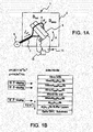
Fig. 1A is a schematic diagram showing a nuclear-spin polarization device 1. -
Fig. 1B is a diagram showing a two-dimensional quantum structure as a measurement object of the nuclear-spin polarization device 1. -
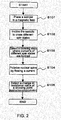
Fig. 2 is a flowchart showing the operation of the nuclear-spin polarization device 1. -
Fig. 3 is an exemplary diagram for explaining S102 inFig. 2 . -
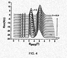
Fig. 4 is a diagram for explaining S103 inFig. 2 . -
Fig. 5A is a diagram showing an example of the measurement of the resistance change at a crossing position between the Landau-level separation and the Zeeman-level separation. -
Fig. 5B is a diagram showing an example of the measurement of the resistance change at a crossing position between the Landau-level separation and the Zeeman-level separation. -
Fig. 5C is a diagram showing an example of the measurement of the resistance change at a crossing position between the Landau-level separation and the Zeeman-level separation. - Hereinbelow, an embodiment of this invention will be described in detail with reference to the drawings.
- First, referring to
Figs. 1A and 1B , the structure of a nuclear-spin polarization device 1 according to this embodiment will be briefly described. - As shown in
Fig. 1A , the nuclear-spin polarization device 1 has a chamber 2 and, in the chamber 2, aninclining device 5 such as a known actuator is provided as a crossing part holding and inclining in a magnetic field asample 3 having a two-dimensional quantum structure with a large g-factor. Further, acoil 7 is wound around so as to cover the outside of thesample 3 and is connected to a power supply 9. That is, it is possible to apply an AC magnetic field to thesample 3 by flowing an alternating current Irf through thecoil 7 using the power supply 9. - Further, the nuclear-spin polarization device 1 has a power supply 11 (polarizing part) flowing a current through the
sample 3 and aresistance measuring device 13 measuring the resistance change when the current is flowed. - The nuclear-spin polarization device 1 of this invention is a device polarizing nuclear spins of a two-dimensional quantum structure with a large g-factor, such as InSb, InAs, or InGaAs systems. The two-dimensional quantum structure is, for example, as shown in
Fig. 1B , a structure having an InSb quantum well sandwiched between AllnSb barriers. - Next, a nuclear-spin polarization and detection method using the nuclear-spin polarization device 1 will be described with reference to
Fig. 2 . - First, as shown in
Fig. 2 , thesample 3 having the two-dimensional quantum structure such as InSb, InAs, or InGaAs systems is placed in the nuclear-spin polarization device 1 and a magnetic field is applied thereto. Specifically, using a non-illustrated superconducting magnet or the like disposed on the outside of the chamber 2, a DC magnetic field is applied in a vertical direction inFig. 1A . That is, thesample 3 is placed in the magnetic field (S101).
The strength of the magnetic field is, for example, about 8T. - (a) Then, as shown in
Fig. 2 , thesample 3 is inclined in the magnetic field using theinclining device 5 to create a state where the Landau-level separation and the Zeeman-level separation are equal to each other, thereby crossing different spin states (S102). - Herein, S102 will be described in further detail with reference to
Fig. 3 . - As shown in
Fig. 3 , the Landau-level separation is determined only by the value of a perpendicular magnetic field while the Zeeman-level separation is determined by the total magnetic field including not only a perpendicular magnetic field but also a parallel magnetic field. - Therefore, in a structure with a relatively large electron g-factor, for example, a quantum structure using a substance such as InSb (g-factor is 30 or more) with a g-faotor greater than that of GaAs (g-factor is about 0.5), such as an InSb two-dimensional quantum well, it is possible to cross different spin states of different Landau levels by inclining the
sample 3. - (b) Then, as shown in
Fig. 2 , the electrical properties of crossing states are examined, thereby selecting the crossing state where domains of different spin states are formed at crossing (S103). - Specifically, as shown in
Fig. 4 , the relationship between the perpendicular magnetic field and the longitudinal resistance (quantum Hall effect) is measured per inclination angle and then a position with a new peak appearing is detected using a known detection device (selecting part) such as a computer. - That is, in
Fig. 4 , crossing between a downward spin of the 0th (ground state) Landau level and an upward spin of the 1st Landau level has occurred at an inclination angle of about 58° to 59° and a new peak appearing in a region of v=2 shows that domains of two different spin states are formed at the crossing point. - The inclination angle in
Fig. 4 represents an inclination angle assuming that the state of thesample 3 in a state where a two-dimensional electron surface in thesample 3 is perpendicular to the magnetic field application direction is given as an angle of 0 degrees (the magnetic field becomes perfectly parallel to the two-dimensional surface at an inclination angle of 90°). - (c) Then, as shown in
Fig. 2 , nuclear spins are polarized by flowing a current through thesample 3 using the power supply 11 (S104). - Specifically, the current which is 10 to 100 times greater than a current for use in normal quantum Hall effect measurement is caused to flow.
- (d) Then, as shown in
Fig. 2 , nuclear-spin polarization in thesample 3 is read (S105). - Specifically, since the resistance value at the crossing point slightly changes due to the nuclear-spin polarization, the nuclear-spin polarization is read (detected) by detecting this change in resistance value using the
resistance measuring device 13. - The above is the nuclear-spin polarization and detection method.
- As described above, according to this embodiment, the nuclear-spin polarization device 1 creates the state where the Landau-level separation and the Zeeman-level separation in the
sample 3 are equal to each other in the magnetic field, thereby crossing the different spin states, and detects the nuclear-spin polarization from the resistance change at the crossing point caused by the nuclear-spin polarization. - Therefore, the nuclear-spin polarization device 1 can detect the nuclear-spin polarization in the two-dimensional quantum structure.
- Hereinbelow, this invention will be described in further detail with reference to an Example.
- Using the nuclear-spin polarization device 1 shown in
Fig. 1A , an attempt was made to detect nuclear-spin polarization in InSb.
The specific sequence is as follows. - First, an InSb two-dimensional quantum structure having the structure shown in
Fig. 1B was prepared as a nuclear-spin polarization detection object. - Then, a Hall bar structure having a width of 40µm and a length of 170µm between voltage measurement terminals was formed on the InSb two-dimensional quantum structure shown in
Fig. 1B using a photolithography process, thereby preparing thesample 3. - Then, the
prepared sample 3 was placed in the nuclear-spin polarization device 1 and was applied with a magnetic field. In this Example, a DC magnetic field was applied in the vertical direction inFig. 1A using the non-illustrated superconducting magnet or the like disposed on the outside of the chamber 2 while changing the magnetic field from 0 to 15T, wherein the magnetic field was changed while changing the inclination angle of thesample 3 by rotating it using theinclining device 5, thereby measuring the magnetoresistive effect. - Then, referring to the test results, it was confirmed that the state where the Landau-level separation and the Zeeman-level separation were equal to each other could be achieved at an inclination angle of about 57.3° to 60.8°, and details of the relationship between the perpendicular magnetic field and the longitudinal resistance (details of the quantum Hall effect) were measured in this range. The temperature in the measurement was set to 100mK using a known cooling device.
- As a result, actually, as shown in
Fig. 4 , a new peak was detected at an angle of about 58° to 59° and thus it was seen that crossing between a downward spin of the 0th (ground state) Landau level and an upward spin of the 1 st Landau level had occurred in a region of v=2 and thus that domains of two different spin states were formed. - Then, in order to polarize nuclear spins, a current of 1.4µA was caused to flow through the
sample 3 using thepower supply 11. - Then, the resistance change at the crossing point was measured using the
resistance measuring device 13.
Specifically, by flowing alternating currents through thecoil 7 wound around the outside of thesample 3, oscillating magnetic fields corresponding to resonant frequencies of In nuclei and Sb nuclei were applied to thesample 3. - As a result, as shown in
Figs. 5A to C , it was seen that the resistance values at the crossing point had decreased. - This means that the resistance values which were increased by the nuclear-spin polarization were reduced by applying the oscillating magnetic fields corresponding to the resonant frequencies of In nuclei and Sb nuclei, that is, this shows that the nuclear-spin polarization was detected. Taking into account altogether these results, the temporal change in resistance value when the current was flowed, and the slow change in resistance value after the resistance change due to the resonant frequency, it was confirmed that the resistance change reflected the degree of nuclear-spin polarization and, conversely, that the degree of nuclear-spin polarization could be detected by the resistance.
- Further, from the results shown in
Figs. 5A to C , it was seen that high-sensitivity resistance detection nuclear magnetic resonance (NMR) had been realized in the InSb two-dimensional quantum structure. - From the results described above, it was seen that the nuclear-spin polarization in InSb could be detected using the nuclear-spin polarization device 1.
- In the above-mentioned Example, the description has been given of the case where the nuclear spins in the InSb two-dimensional quantum structure were detected. However, this invention is not particularly limited thereto and is of course also applicable to a two-dimensional quantum structure with a large g-factor, such as InAs or InGaAs systems.
- Further, the nuclear-spin detection device of this invention is applicable to NMR, a quantum computer using NMR, or a semiconductor strain detection device.
-
- 1
- nuclear-spin polarization device
- 2
- chamber
- 3
- sample
- 5
- inclining device
- 7
- coil
- 9
- power supply
- 11
- power supply
- 13
- resistance measuring device
Claims (13)
- Anudear-spin polarization detection device characterized by comprising
a crossing part that inclines a two-dimensional quantum structure in a magnetic field to cross Landau-level separation and Zeeman-level separation, and
a polarizing part that polarizes nuclear spins in the two-dimensional quantum structure,
wherein the device detects polarization of the nuclear spins at a position where the Landau-level separation and the Zeeman-level separation are crossed by the crossing part. - The nuclear-spin polarization detection device according to claim 1, characterized in that the polarizing part polarizes the nuclear spins by flowing a current through the two-dimensional quantum structure.
- The nuclear-spin polarization detection device according to claim 2, characterized by comprising a selecting part that selects a position, where domains of different spin states are formed at crossing, from positions where the Landau-level separation and the Zeeman-level separation are crossed by the crossing part,
wherein the device detects the polarization of the nuclear spins at the position selected by the selecting part. - The nuclear-spin polarization detection device according to claim 2 or 3, characterized by detecting the polarization of the nuclear spins from a resistance change at the position where the Landau-level separation and the Zeeman-level separation are crossed by the crossing part when the current is flowed through the two-dimensional quantum structure.
- The nuclear-spin polarization detection device according to any one of claims 1 to 4, characterized in that the two-dimensional quantum structure is one of InSb, InAs, and InGaAs systems.
- A nuclear magnetic resonance device characterized by comprising the nuclear-spin polarization detection device according to any one of claims 1 to 5.
- A quantum computer characterized by comprising the nuclear magnetic resonance device according to claim 6.
- A semiconductor strain detection device characterized by comprising the nuclear-spin polarization detection device according to any one of claims 1 to 5.
- A nuclear-spin polarization detection method characterized by comprising(a) inclining a two-dimensional quantum structure in a magnetic field to cross Landau-level separation and Zeeman-level separation,(c) polarizing nuclear spins in the two-dimensional quantum structure, and(d) detecting polarization of the nuclear spins at a position where the Landau-level separation and the Zeeman-level separation are crossed by said (a).
- The nuclear-spin polarization detection method according to claim 9, characterized in that said (c) polarizes the nuclear spins by flowing a current through the two-dimensional quantum structure.
- The nuclear-spin polarization detection method according to claim 10, characterized by further comprising (b) that is carried out between said (a) and said (c) and selects a position, where domains of different spin states are formed at crossing, from positions where the Landau-level separation and the Zeeman-level separation are crossed by said (a),
wherein said (d) detects the polarization of the nuclear spins at the position selected by said (b). - The nuclear-spin polarization detection method according to claim 10 or 11, characterized by detecting the polarization of the nuclear spins from a resistance change at the position where the Landau-level separation and the Zeeman-level separation are crossed by said (a) when the current is flowed through the two-dimensional quantum structure.
- The nuclear-spin polarization detection method according to any one of claims 9 to 12, characterized in that the two-dimensional quantum structure is one of InSb, InAs, and InGaAs systems.
Applications Claiming Priority (2)
| Application Number | Priority Date | Filing Date | Title |
|---|---|---|---|
| JP2009287150 | 2009-12-18 | ||
| PCT/JP2010/072438 WO2011074558A1 (en) | 2009-12-18 | 2010-12-14 | Nuclear-spin polarization detection device and nuclear-spin polarization detection method |
Publications (2)
| Publication Number | Publication Date |
|---|---|
| EP2515134A1 true EP2515134A1 (en) | 2012-10-24 |
| EP2515134A4 EP2515134A4 (en) | 2013-09-18 |
Family
ID=44167311
Family Applications (1)
| Application Number | Title | Priority Date | Filing Date |
|---|---|---|---|
| EP10837584.1A Withdrawn EP2515134A4 (en) | 2009-12-18 | 2010-12-14 | NUCLEAR SPIN POLARIZATION DETECTION DEVICE AND NUCLEAR SPIN POLARIZATION DETECTION METHOD |
Country Status (4)
| Country | Link |
|---|---|
| US (1) | US9310449B2 (en) |
| EP (1) | EP2515134A4 (en) |
| JP (1) | JP5569945B2 (en) |
| WO (1) | WO2011074558A1 (en) |
Families Citing this family (2)
| Publication number | Priority date | Publication date | Assignee | Title |
|---|---|---|---|---|
| JP2014027074A (en) * | 2012-07-26 | 2014-02-06 | Nippon Telegr & Teleph Corp <Ntt> | Nuclear spin state control method, detection method, control device, and detection device |
| CN112113991B (en) * | 2020-09-25 | 2021-08-31 | 吉林大学 | A non-local resistive nuclear magnetic resonance measurement method |
Family Cites Families (6)
| Publication number | Priority date | Publication date | Assignee | Title |
|---|---|---|---|---|
| JPH08220033A (en) | 1995-02-08 | 1996-08-30 | Yamagata Pref Gov Technopolis Zaidan | Paramagnetic species analysis method |
| US5917322A (en) * | 1996-10-08 | 1999-06-29 | Massachusetts Institute Of Technology | Method and apparatus for quantum information processing |
| US7184555B2 (en) * | 2001-04-11 | 2007-02-27 | Magiq Technologies, Inc. | Quantum computation |
| US7148683B2 (en) * | 2001-10-25 | 2006-12-12 | Intematix Corporation | Detection with evanescent wave probe |
| US7291891B2 (en) * | 2001-12-06 | 2007-11-06 | Japan Science And Technology Agency | In-solid nuclear spin quantum calculation device |
| JP2006066603A (en) * | 2004-08-26 | 2006-03-09 | Nippon Telegr & Teleph Corp <Ntt> | Nuclear spin state controller and detector |
-
2010
- 2010-12-14 WO PCT/JP2010/072438 patent/WO2011074558A1/en not_active Ceased
- 2010-12-14 EP EP10837584.1A patent/EP2515134A4/en not_active Withdrawn
- 2010-12-14 US US13/516,380 patent/US9310449B2/en not_active Expired - Fee Related
- 2010-12-14 JP JP2011546122A patent/JP5569945B2/en not_active Expired - Fee Related
Non-Patent Citations (5)
| Title |
|---|
| LIU H W ET AL: "Dynamic nuclear polarization and nuclear magnetic resonance in the simplest pseudospin quantum Hall ferromagnet", PHYSICAL REVIEW B (CONDENSED MATTER AND MATERIALS PHYSICS) AMERICAN PHYSICAL SOCIETY USA, vol. 82, no. 24, 8 December 2010 (2010-12-08), XP002709705, ISSN: 1098-0121 * |
| MELINTE S ET AL: "Spin polarization of two-dimensional electrons in GaAs quantum wells around Landau level filling [nu]=1 from NMR measurements of gallium nuclei", PHYSICAL REVIEW B (CONDENSED MATTER AND MATERIALS PHYSICS) APS THROUGH AIP USA, vol. 64, no. 8, 8 August 2001 (2001-08-08) , pages 085327/1-9, XP002709938, ISSN: 0163-1829 * |
| MURAKI K ET AL: "Nuclear spin manipulation in semiconductor nanostructures", PROCEEDINGS OF SPIE - THE INTERNATIONAL SOCIETY FOR OPTICAL ENGINEERING - DEVICE AND PROCESS TECHNOLOGIES FOR MICROELECTRONICS, MEMS, PHOTONICS, AND NANOTECHNOLOGY IV 2008 SPIE US, vol. 6800, 5 December 2007 (2007-12-05), XP002709939, DOI: 10.1117/12.767747 * |
| OTA T ET AL: "Nuclear spin population and its control toward initialization using an all-electrical submicron scale nuclear magnetic resonance device", APPLIED PHYSICS LETTERS, AIP, AMERICAN INSTITUTE OF PHYSICS, MELVILLE, NY, US, vol. 90, no. 10, 8 March 2007 (2007-03-08) , pages 102118-102118, XP012093465, ISSN: 0003-6951, DOI: 10.1063/1.2711520 * |
| See also references of WO2011074558A1 * |
Also Published As
| Publication number | Publication date |
|---|---|
| WO2011074558A1 (en) | 2011-06-23 |
| JPWO2011074558A1 (en) | 2013-04-25 |
| JP5569945B2 (en) | 2014-08-13 |
| US20120256629A1 (en) | 2012-10-11 |
| EP2515134A4 (en) | 2013-09-18 |
| US9310449B2 (en) | 2016-04-12 |
Similar Documents
| Publication | Publication Date | Title |
|---|---|---|
| Fang et al. | Spin–orbit-driven ferromagnetic resonance | |
| Bi et al. | Room-temperature electronically-controlled ferromagnetism at the LaAlO3/SrTiO3 interface | |
| Wernsdorfer et al. | Landau–Zener method to study quantum phase interference of Fe 8 molecular nanomagnets | |
| Yokouchi et al. | Formation of in-plane skyrmions in epitaxial MnSi thin films as revealed by planar Hall effect | |
| Sun et al. | Kondo resonance in a multiprobe quantum dot | |
| Su et al. | Linear anisotropic magnetoresistive sensor without barber-pole electrodes | |
| Salis et al. | Signatures of dynamically polarized nuclear spins in all-electrical lateral spin transport devices | |
| de Melo et al. | Unveiling transport properties of Co2MnSi Heusler epitaxial thin films with ultra-low magnetic damping | |
| Goel et al. | Room-temperature spin injection from a ferromagnetic semiconductor | |
| Kohda et al. | Manipulating spin–orbit interaction in semiconductors | |
| Meier et al. | Field effect in InAs/permalloy hybrid transistors | |
| US9310449B2 (en) | Nuclear-spin polarization detection device and nuclear-spin polarization detection method | |
| Ihara et al. | Field-induced magnetic structures in the chiral polar antiferromagnet Ni 2 InSbO 6 | |
| Lorke et al. | Local far-infrared spectroscopy of edge states in the quantum Hall regime | |
| Ferguson et al. | Local potential distribution generates edge currents in a magnetic topological insulator | |
| CN112113991B (en) | A non-local resistive nuclear magnetic resonance measurement method | |
| Ferguson et al. | Imaging signatures of edge currents in a magnetic topological insulator | |
| Naydenova et al. | Diffusion thermopower of (ga, mn) as/gaas tunnel junctions | |
| Fauzi et al. | All electrical probe of nuclear spin polarization and relaxation by spin phase transition peaks of the filling fraction ν= 2/3 quantum hall effect | |
| Yang et al. | The magnetic tunnel junction as a temperature sensor for buried nanostructures | |
| Bai et al. | Anisotropy and damping in Co2FeAl0. 5Si0. 5 via electrical detection of ferromagnetic resonance | |
| Yang et al. | Orbital enhanced intrinsic nonlinear planar Hall effect for probing topological phase transition in CuTlSe $ _ {2} $ | |
| Johnson | Spin injection | |
| Ney | A new design of an UHV-High-Tc-SQUID magnetometer: Absolute determination of magnetic moments of 3d-transition metal films | |
| Fang | Current-induced torque driven ferromagnetic resonance in magnetic microstructures |
Legal Events
| Date | Code | Title | Description |
|---|---|---|---|
| PUAI | Public reference made under article 153(3) epc to a published international application that has entered the european phase |
Free format text: ORIGINAL CODE: 0009012 |
|
| 17P | Request for examination filed |
Effective date: 20120718 |
|
| AK | Designated contracting states |
Kind code of ref document: A1 Designated state(s): AL AT BE BG CH CY CZ DE DK EE ES FI FR GB GR HR HU IE IS IT LI LT LU LV MC MK MT NL NO PL PT RO RS SE SI SK SM TR |
|
| DAX | Request for extension of the european patent (deleted) | ||
| RIC1 | Information provided on ipc code assigned before grant |
Ipc: G01R 33/32 20060101ALI20130808BHEP Ipc: G01R 33/30 20060101ALN20130808BHEP Ipc: H01L 29/66 20060101ALN20130808BHEP Ipc: G06N 99/00 20100101ALN20130808BHEP Ipc: G01N 24/08 20060101AFI20130808BHEP Ipc: B82Y 10/00 20110101ALN20130808BHEP |
|
| A4 | Supplementary search report drawn up and despatched |
Effective date: 20130821 |
|
| 17Q | First examination report despatched |
Effective date: 20160527 |
|
| GRAP | Despatch of communication of intention to grant a patent |
Free format text: ORIGINAL CODE: EPIDOSNIGR1 |
|
| RIC1 | Information provided on ipc code assigned before grant |
Ipc: B82Y 10/00 20110101ALN20190227BHEP Ipc: G06N 99/00 20190101ALN20190227BHEP Ipc: G01R 33/30 20060101ALN20190227BHEP Ipc: G01N 24/08 20060101AFI20190227BHEP Ipc: G01R 33/32 20060101ALI20190227BHEP Ipc: H01L 29/66 20060101ALN20190227BHEP |
|
| INTG | Intention to grant announced |
Effective date: 20190403 |
|
| STAA | Information on the status of an ep patent application or granted ep patent |
Free format text: STATUS: THE APPLICATION IS DEEMED TO BE WITHDRAWN |
|
| 18D | Application deemed to be withdrawn |
Effective date: 20190814 |