EP2515065A1 - A heat exchanger - Google Patents
A heat exchanger Download PDFInfo
- Publication number
- EP2515065A1 EP2515065A1 EP11163491A EP11163491A EP2515065A1 EP 2515065 A1 EP2515065 A1 EP 2515065A1 EP 11163491 A EP11163491 A EP 11163491A EP 11163491 A EP11163491 A EP 11163491A EP 2515065 A1 EP2515065 A1 EP 2515065A1
- Authority
- EP
- European Patent Office
- Prior art keywords
- heat exchanger
- fins
- meander
- tubes
- air
- Prior art date
- Legal status (The legal status is an assumption and is not a legal conclusion. Google has not performed a legal analysis and makes no representation as to the accuracy of the status listed.)
- Granted
Links
Images


Classifications
-
- F—MECHANICAL ENGINEERING; LIGHTING; HEATING; WEAPONS; BLASTING
- F28—HEAT EXCHANGE IN GENERAL
- F28F—DETAILS OF HEAT-EXCHANGE AND HEAT-TRANSFER APPARATUS, OF GENERAL APPLICATION
- F28F1/00—Tubular elements; Assemblies of tubular elements
- F28F1/10—Tubular elements and assemblies thereof with means for increasing heat-transfer area, e.g. with fins, with projections, with recesses
- F28F1/12—Tubular elements and assemblies thereof with means for increasing heat-transfer area, e.g. with fins, with projections, with recesses the means being only outside the tubular element
- F28F1/126—Tubular elements and assemblies thereof with means for increasing heat-transfer area, e.g. with fins, with projections, with recesses the means being only outside the tubular element consisting of zig-zag shaped fins
-
- F—MECHANICAL ENGINEERING; LIGHTING; HEATING; WEAPONS; BLASTING
- F28—HEAT EXCHANGE IN GENERAL
- F28F—DETAILS OF HEAT-EXCHANGE AND HEAT-TRANSFER APPARATUS, OF GENERAL APPLICATION
- F28F17/00—Removing ice or water from heat-exchange apparatus
- F28F17/005—Means for draining condensates from heat exchangers, e.g. from evaporators
Definitions
- the invention relates to a heat exchanger, notably a micro-channel heat exchanger.
- the invention further relates to an air conditioning system.
- the known heat exchanger comprises a plurality of parallel fins arranged between the adjacent tubes.
- the known fins have a substantially uniform depth and may be arranged in a suitable profile, like a zigzag between the adjacent tubes.
- An inflowing air stream impinging on the fins of the known heat exchanger is intercepted by the whole cross-section of the fin structure arranged between the tubes.
- a heat exchanger notably a micro-channel heat exchanger with improved operational characteristics.
- an improved heat exchanger in particular it is an object of the invention to provide a heat exchanger having improved fin structure.
- the heat exchanger comprises a first set of tubes enclosing a second set of fins, the first set of tubes cooperating with a manifold, characterized in that the fins of the second set are substantially meander or canted -shaped having a number of substantially mutually parallel surfaces in a direction transverse to the meander propagation direction, wherein a depth profile is provided in the said mutually parallel surfaces.
- the fin structure has a reduced resistance for the inflowing stream of air. It particular, it is found advantageous that the substantially parallel surfaces of the meander structure are shaped as respective openings diverging towards the external face of the heat exchanger conceived to intercept the inflowing stream of air.
- the depth profile provided in the substantially parallel surfaces of the fins is V-shaped, having the wider portion of the V-shape at an external face of the heat exchanger conceived to receive an inflowing stream of air.
- the heat exchanger is less sensitive to particle contamination present in the inflowing stream of air, which contributed to the improved operational characteristics of the heat exchanger according to the invention.
- the heat exchanger having the V-shaped depth profiles in the substantially parallel surfaces of the fins has an increased cooling capacity in condensing or frost accumulating conditions. This may be explained by the fact that in the heat exchanger according to the invention an improved water draining capacity is achieved.
- the depth profile is provided for a portion of the said meander of canted shape.
- the invention further relates to an air conditioning device comprising the heat exchanger as is discussed with reference to the foregoing.
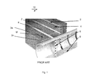
- FIG. 1 presents in a schematic way an embodiment of a known heat exchanger.
- the known heat exchanger 10 comprises a set of tubes 2 enclosing a set of fins 4, which may propagate according to a meander shape in a meander propagation direction M.
- the fins 4 in the meander structure form mutually substantially parallel surface 3a, ..., 3n, which are transversely arranged to the tubes 2.
- the surfaces 3a, ...3n are substantially perpendicular to the tubes 2.
- the known heat exchanger 10 further comprises a manifold 8 comprising a set of channels 6.
- the known heat exchanger has a limitation that the spaces between the substantially parallel surfaces 3a, ..., 3n may be polluted with particles present in the inflowing air thereby reducing cooling capacity of the known heat exchanger.
- FIG. 2 presents in a schematic way an embodiment, based on standard heat exchanger 10, of the heat exchanger 20 according to an aspect of the invention having a cross-sectional dimension X, Y and a depth dimension Z.
- the heat exchanger 20 comprises a set of tubes 23 enclosing the set of fins having the substantially parallel surface 22a, ..., 22n.
- the fins and the tubes are connected with the manifold 21 provided with channels 21a, ...21n.
- the substantially parallel surfaces 22a, ..., 22n are provided with a depth profile 25, which has a wider portion at a face surface 24 of the fins conceived to intercept the stream of the inflowing air 26. It will be appreciated that the depth profile may have different shapes.
- the depth profile 25 provided in the parallel fins 22a, ..., 22n decrease the resistance for the inflowing air 26.
- the depth profile 25 ensures that the particles possible present in the inflowing air have a lower probability to deposit on the external face portion 24a and thereby to block the pathway of the inflowing air 26 towards the inner volume of the heat exchanger.
- the depth and slant profile 25 provided in the parallel fins 22a, ..., 22n increase the water drain capacity.
- the gravity helps to drains the water so it drips of the point of the canted profile.
- the heat exchanger of the invention has in practice an increased cooling capacity and an increased robustness with respect to operational malfunction.
- FIG. 3 presents in a schematic way an embodiment in a still different shape of the heat exchanger 30 according to an aspect of the invention.
- the cross-sectional view shows the staggered tubes 37 with the parallelogram shaped fins having surfaces 32. Air can enter the heat exchanger with reduced flow resistance due to the V-shaped profile 36 and water drains itself easy from the projecting edge of the tube 37.
- FIG 4 presents in a schematic way a further embodiment of the heat exchanger 40 according to a still further aspect of the invention.
- the tubes 42 and the fins 41 are affixed to the manifold 43.
- the fins 41 are provided with the depth profile (i.e. groove) as is discussed with the reference to the foregoing along the complete length of the meander structure having a suitable plurality of substantially parallel surfaces (not shown for clarity).
Landscapes
- Engineering & Computer Science (AREA)
- Physics & Mathematics (AREA)
- Thermal Sciences (AREA)
- Mechanical Engineering (AREA)
- General Engineering & Computer Science (AREA)
- Geometry (AREA)
- Heat-Exchange Devices With Radiators And Conduit Assemblies (AREA)
Abstract
Description
- The invention relates to a heat exchanger, notably a micro-channel heat exchanger.
- The invention further relates to an air conditioning system.
- An embodiment of a heat exchanger is known from
US 7, 281, 387 . The known heat exchanger comprises a plurality of parallel fins arranged between the adjacent tubes. The known fins have a substantially uniform depth and may be arranged in a suitable profile, like a zigzag between the adjacent tubes. An inflowing air stream impinging on the fins of the known heat exchanger is intercepted by the whole cross-section of the fin structure arranged between the tubes. - It is a disadvantage of the known heat exchanger that the relatively fine structure of the fin sequence is relatively sensitive for particle contamination present in the inflowing air stream. When such particle contamination is deposited on the fins or between the fins local efficiency of the known heat exchanger may be substantially reduced.
- It is a still further disadvantage of the known heat exchanger that air cooling applications may be impeded by water condensing on the surfaces of the individual fins. The known fins structure is not able to drain this water, so it accumulates in the fine fin structure, thereby blocking the stream of the inflowing air.
- It is a still further disadvantage of the known heat exchanger that for air cooling applications aiming at the target evaporator temperatures below zero degrees centigrade undesirable frost may be accumulated on the surfaces of the individual fins substantially reducing the overall efficiency of the heat exchanger. The fact that the known fin structure is not able to drain water well, defrost cycles are not effective. The melt water during the defrost cycle accumulates in the fine fin structure. Subsequently this water is transformed into substantially solid ice formations and blocking the air flow.
- It is an object of the invention to provide a heat exchanger, notably a micro-channel heat exchanger with improved operational characteristics. In particular, it is an object of the invention to provide an improved heat exchanger, in particular it is an object of the invention to provide a heat exchanger having improved fin structure.
- To this end the heat exchanger according to an aspect of the invention comprises a first set of tubes enclosing a second set of fins, the first set of tubes cooperating with a manifold, characterized in that the fins of the second set are substantially meander or canted -shaped having a number of substantially mutually parallel surfaces in a direction transverse to the meander propagation direction, wherein a depth profile is provided in the said mutually parallel surfaces.
- An additional advantage is that the fin structure has a reduced resistance for the inflowing stream of air. It particular, it is found advantageous that the substantially parallel surfaces of the meander structure are shaped as respective openings diverging towards the external face of the heat exchanger conceived to intercept the inflowing stream of air.
- In a particular embodiment of the heat exchanger the depth profile provided in the substantially parallel surfaces of the fins is V-shaped, having the wider portion of the V-shape at an external face of the heat exchanger conceived to receive an inflowing stream of air.
- It is found that in this particular embodiment the heat exchanger is less sensitive to particle contamination present in the inflowing stream of air, which contributed to the improved operational characteristics of the heat exchanger according to the invention.
- It is further found that the heat exchanger having the V-shaped depth profiles in the substantially parallel surfaces of the fins has an increased cooling capacity in condensing or frost accumulating conditions.. This may be explained by the fact that in the heat exchanger according to the invention an improved water draining capacity is achieved.
- In a still further embodiment of the heat exchanger according to the invention the depth profile is provided for a portion of the said meander of canted shape.
- It is found that for some circumstances it may be sufficient to provide the depth profile in the substantially parallel surfaces of the fins only for a portion of the fins forming the meander structure.
- The invention further relates to an air conditioning device comprising the heat exchanger as is discussed with reference to the foregoing.
- These and other aspects of the invention will be discussed with reference to drawings wherein like reference signs correspond to like elements. It will be appreciated that the drawings are presented for illustrative purposes only and may not be used for limiting the scope of the appended claims.
-
-
Figure 1 presents in a schematic way an embodiment of a known heat exchanger. -
Figure 2 presents in a schematic way an embodiment of the heat exchanger according to an aspect of the invention. -
Figure 3 presents in a schematic way an embodiment of the heat exchanger according to a further aspect of the invention. -
Figure 4 presents in a schematic way a further embodiment of the heat exchanger according to a still further aspect of the invention. -
Figure 1 presents in a schematic way an embodiment of a known heat exchanger. The knownheat exchanger 10 comprises a set oftubes 2 enclosing a set offins 4, which may propagate according to a meander shape in a meander propagation direction M. Thefins 4 in the meander structure form mutually substantiallyparallel surface 3a, ..., 3n, which are transversely arranged to thetubes 2. Preferably, thesurfaces 3a, ...3n are substantially perpendicular to thetubes 2. The knownheat exchanger 10 further comprises amanifold 8 comprising a set ofchannels 6. - It is found that the known heat exchanger has a limitation that the spaces between the substantially
parallel surfaces 3a, ..., 3n may be polluted with particles present in the inflowing air thereby reducing cooling capacity of the known heat exchanger. -
Figure 2 presents in a schematic way an embodiment, based onstandard heat exchanger 10, of theheat exchanger 20 according to an aspect of the invention having a cross-sectional dimension X, Y and a depth dimension Z. Theheat exchanger 20 comprises a set oftubes 23 enclosing the set of fins having the substantiallyparallel surface 22a, ..., 22n. The fins and the tubes are connected with themanifold 21 provided withchannels 21a, ...21n. - In accordance with the invention the substantially
parallel surfaces 22a, ..., 22n are provided with adepth profile 25, which has a wider portion at aface surface 24 of the fins conceived to intercept the stream of the inflowingair 26. It will be appreciated that the depth profile may have different shapes. - In accordance with the invention, the
depth profile 25 provided in theparallel fins 22a, ..., 22n decrease the resistance for the inflowingair 26. In addition, thedepth profile 25 ensures that the particles possible present in the inflowing air have a lower probability to deposit on theexternal face portion 24a and thereby to block the pathway of the inflowingair 26 towards the inner volume of the heat exchanger. - In accordance with the invention, the depth and
slant profile 25 provided in theparallel fins 22a, ..., 22n increase the water drain capacity. In addition, with horizontal application of the heat exchanger, with het profiled air intake surface facing the ground, the gravity helps to drains the water so it drips of the point of the canted profile. - Accordingly, the heat exchanger of the invention has in practice an increased cooling capacity and an increased robustness with respect to operational malfunction.
-
Figure 3 presents in a schematic way an embodiment in a still different shape of theheat exchanger 30 according to an aspect of the invention. In the cross-sectional view shows the staggeredtubes 37 with the parallelogram shapedfins having surfaces 32. Air can enter the heat exchanger with reduced flow resistance due to the V-shaped profile 36 and water drains itself easy from the projecting edge of thetube 37. -
Figure 4 presents in a schematic way a further embodiment of theheat exchanger 40 according to a still further aspect of the invention. In this embodiment thetubes 42 and thefins 41 are affixed to themanifold 43. Thefins 41 are provided with the depth profile (i.e. groove) as is discussed with the reference to the foregoing along the complete length of the meander structure having a suitable plurality of substantially parallel surfaces (not shown for clarity). - While specific embodiments have been described above, it will be appreciated that the invention may be practiced otherwise than as described. Moreover, specific items discussed with reference to any of the isolated drawings may freely be inter-changed supplementing each outer in any particular way. The descriptions above are intended to be illustrative, not limiting. Thus, it will be apparent to one skilled in the art that modifications may be made to the invention as described in the foregoing without departing from the scope of the claims set out below.
Claims (4)
- A heat exchanger comprising a first set of tubes enclosing a second set of fins, the first set of tubes cooperating with a manifold, characterized in that the fins of the second set are substantially meander or canted-shaped having a number of substantially mutually parallel surfaces in a direction transverse to the meander propagation direction, wherein a depth profile is provided in the said mutually parallel surfaces.
- The heat exchanger according to claim 1, wherein the depth profile is V-shaped, having the wider portion of the V-shape at an external face of the heat exchanger conceived to receive an inflowing stream of air.
- The heat exchanger according to claim 1 or 2, wherein the depth profile is provided for a portion of the said meander or canted shape.
- An air conditioning system comprising a heat exchanger according to any one of the preceding claims.
Priority Applications (1)
| Application Number | Priority Date | Filing Date | Title |
|---|---|---|---|
| EP11163491.1A EP2515065B1 (en) | 2011-04-21 | 2011-04-21 | A heat exchanger |
Applications Claiming Priority (1)
| Application Number | Priority Date | Filing Date | Title |
|---|---|---|---|
| EP11163491.1A EP2515065B1 (en) | 2011-04-21 | 2011-04-21 | A heat exchanger |
Publications (2)
| Publication Number | Publication Date |
|---|---|
| EP2515065A1 true EP2515065A1 (en) | 2012-10-24 |
| EP2515065B1 EP2515065B1 (en) | 2019-11-06 |
Family
ID=44358088
Family Applications (1)
| Application Number | Title | Priority Date | Filing Date |
|---|---|---|---|
| EP11163491.1A Active EP2515065B1 (en) | 2011-04-21 | 2011-04-21 | A heat exchanger |
Country Status (1)
| Country | Link |
|---|---|
| EP (1) | EP2515065B1 (en) |
Citations (4)
| Publication number | Priority date | Publication date | Assignee | Title |
|---|---|---|---|---|
| JPS58160797A (en) * | 1982-03-19 | 1983-09-24 | Nippon Light Metal Co Ltd | Heat exchanger |
| US7281387B2 (en) | 2004-04-29 | 2007-10-16 | Carrier Commercial Refrigeration Inc. | Foul-resistant condenser using microchannel tubing |
| US20100006276A1 (en) * | 2008-07-11 | 2010-01-14 | Johnson Controls Technology Company | Multichannel Heat Exchanger |
| WO2011034633A1 (en) * | 2009-09-16 | 2011-03-24 | Carrier Corporation | Free-draining finned surface architecture for a heat exchanger |
-
2011
- 2011-04-21 EP EP11163491.1A patent/EP2515065B1/en active Active
Patent Citations (4)
| Publication number | Priority date | Publication date | Assignee | Title |
|---|---|---|---|---|
| JPS58160797A (en) * | 1982-03-19 | 1983-09-24 | Nippon Light Metal Co Ltd | Heat exchanger |
| US7281387B2 (en) | 2004-04-29 | 2007-10-16 | Carrier Commercial Refrigeration Inc. | Foul-resistant condenser using microchannel tubing |
| US20100006276A1 (en) * | 2008-07-11 | 2010-01-14 | Johnson Controls Technology Company | Multichannel Heat Exchanger |
| WO2011034633A1 (en) * | 2009-09-16 | 2011-03-24 | Carrier Corporation | Free-draining finned surface architecture for a heat exchanger |
Also Published As
| Publication number | Publication date |
|---|---|
| EP2515065B1 (en) | 2019-11-06 |
Similar Documents
| Publication | Publication Date | Title |
|---|---|---|
| CN102889820B (en) | For condensate water guide structure and the heat exchanger of heat exchanger | |
| US20140262188A1 (en) | Fin Spacing On An Evaporative Atmospheric Water Condenser | |
| CN204438875U (en) | Fin and the heat exchanger with it | |
| CN103261828B (en) | Heat exchanger and the air conditioner being provided with this heat exchanger | |
| JP2015004451A (en) | Fin tube heat exchanger | |
| CN105352345B (en) | Microchannel heat exchanger and air conditioner thereof | |
| CN106322850A (en) | Microchannel heat exchanger, refrigerator and air-cooled refrigerator | |
| US20160195345A1 (en) | Condensate drain devices for heat exchanger coil and methods for making the same | |
| EP3608618B1 (en) | Heat exchanger and refrigeration cycle device | |
| CN105864888A (en) | Microchannel heat exchanger and air conditioner | |
| CN106288526A (en) | Micro-channel heat exchanger and refrigerator, wind cooling refrigerator | |
| WO2018040037A1 (en) | Micro-channel heat exchanger and air-cooled refrigerator | |
| WO2018040036A1 (en) | Micro-channel heat exchanger and air-cooled refrigerator | |
| EP2515065B1 (en) | A heat exchanger | |
| CN202902995U (en) | Condensate water diversion structure for heat exchanger and heat exchanger | |
| WO2018040035A1 (en) | Micro-channel heat exchanger and air-cooled refrigerator | |
| CN106288525A (en) | Micro-channel heat exchanger and refrigerator, wind cooling refrigerator | |
| CN102889819B (en) | Header pipe and heat exchanger | |
| CN106440527B (en) | Fin-free micro-channel heat exchanger | |
| EP3480546B1 (en) | Heat exchanger and refrigeration cycle apparatus provided with same | |
| CN204187896U (en) | Evaporator and air cooler | |
| CN203848558U (en) | Evaporator core | |
| CN102252464A (en) | Heat exchanger | |
| CN104136876B (en) | Parallel flow heat exchanger and air conditioner equipped with the parallel flow heat exchanger | |
| CN106403389A (en) | Micro-channel heat exchanger, refrigerator and air-cooled refrigerator |
Legal Events
| Date | Code | Title | Description |
|---|---|---|---|
| PUAI | Public reference made under article 153(3) epc to a published international application that has entered the european phase |
Free format text: ORIGINAL CODE: 0009012 |
|
| AK | Designated contracting states |
Kind code of ref document: A1 Designated state(s): AL AT BE BG CH CY CZ DE DK EE ES FI FR GB GR HR HU IE IS IT LI LT LU LV MC MK MT NL NO PL PT RO RS SE SI SK SM TR |
|
| AX | Request for extension of the european patent |
Extension state: BA ME |
|
| 17P | Request for examination filed |
Effective date: 20130423 |
|
| RAP1 | Party data changed (applicant data changed or rights of an application transferred) |
Owner name: NEDERLANDSE ORGANISATIE VOOR TOEGEPAST- NATUURWETE |
|
| STAA | Information on the status of an ep patent application or granted ep patent |
Free format text: STATUS: EXAMINATION IS IN PROGRESS |
|
| 17Q | First examination report despatched |
Effective date: 20161128 |
|
| GRAP | Despatch of communication of intention to grant a patent |
Free format text: ORIGINAL CODE: EPIDOSNIGR1 |
|
| STAA | Information on the status of an ep patent application or granted ep patent |
Free format text: STATUS: GRANT OF PATENT IS INTENDED |
|
| INTG | Intention to grant announced |
Effective date: 20190529 |
|
| GRAS | Grant fee paid |
Free format text: ORIGINAL CODE: EPIDOSNIGR3 |
|
| GRAA | (expected) grant |
Free format text: ORIGINAL CODE: 0009210 |
|
| STAA | Information on the status of an ep patent application or granted ep patent |
Free format text: STATUS: THE PATENT HAS BEEN GRANTED |
|
| AK | Designated contracting states |
Kind code of ref document: B1 Designated state(s): AL AT BE BG CH CY CZ DE DK EE ES FI FR GB GR HR HU IE IS IT LI LT LU LV MC MK MT NL NO PL PT RO RS SE SI SK SM TR |
|
| REG | Reference to a national code |
Ref country code: GB Ref legal event code: FG4D |
|
| REG | Reference to a national code |
Ref country code: CH Ref legal event code: EP Ref country code: AT Ref legal event code: REF Ref document number: 1199311 Country of ref document: AT Kind code of ref document: T Effective date: 20191115 |
|
| REG | Reference to a national code |
Ref country code: IE Ref legal event code: FG4D |
|
| REG | Reference to a national code |
Ref country code: DE Ref legal event code: R096 Ref document number: 602011063153 Country of ref document: DE |
|
| REG | Reference to a national code |
Ref country code: NL Ref legal event code: FP |
|
| REG | Reference to a national code |
Ref country code: LT Ref legal event code: MG4D |
|
| PG25 | Lapsed in a contracting state [announced via postgrant information from national office to epo] |
Ref country code: GR Free format text: LAPSE BECAUSE OF FAILURE TO SUBMIT A TRANSLATION OF THE DESCRIPTION OR TO PAY THE FEE WITHIN THE PRESCRIBED TIME-LIMIT Effective date: 20200207 Ref country code: ES Free format text: LAPSE BECAUSE OF FAILURE TO SUBMIT A TRANSLATION OF THE DESCRIPTION OR TO PAY THE FEE WITHIN THE PRESCRIBED TIME-LIMIT Effective date: 20191106 Ref country code: NO Free format text: LAPSE BECAUSE OF FAILURE TO SUBMIT A TRANSLATION OF THE DESCRIPTION OR TO PAY THE FEE WITHIN THE PRESCRIBED TIME-LIMIT Effective date: 20200206 Ref country code: PT Free format text: LAPSE BECAUSE OF FAILURE TO SUBMIT A TRANSLATION OF THE DESCRIPTION OR TO PAY THE FEE WITHIN THE PRESCRIBED TIME-LIMIT Effective date: 20200306 Ref country code: PL Free format text: LAPSE BECAUSE OF FAILURE TO SUBMIT A TRANSLATION OF THE DESCRIPTION OR TO PAY THE FEE WITHIN THE PRESCRIBED TIME-LIMIT Effective date: 20191106 Ref country code: LT Free format text: LAPSE BECAUSE OF FAILURE TO SUBMIT A TRANSLATION OF THE DESCRIPTION OR TO PAY THE FEE WITHIN THE PRESCRIBED TIME-LIMIT Effective date: 20191106 Ref country code: LV Free format text: LAPSE BECAUSE OF FAILURE TO SUBMIT A TRANSLATION OF THE DESCRIPTION OR TO PAY THE FEE WITHIN THE PRESCRIBED TIME-LIMIT Effective date: 20191106 Ref country code: SE Free format text: LAPSE BECAUSE OF FAILURE TO SUBMIT A TRANSLATION OF THE DESCRIPTION OR TO PAY THE FEE WITHIN THE PRESCRIBED TIME-LIMIT Effective date: 20191106 Ref country code: FI Free format text: LAPSE BECAUSE OF FAILURE TO SUBMIT A TRANSLATION OF THE DESCRIPTION OR TO PAY THE FEE WITHIN THE PRESCRIBED TIME-LIMIT Effective date: 20191106 Ref country code: BG Free format text: LAPSE BECAUSE OF FAILURE TO SUBMIT A TRANSLATION OF THE DESCRIPTION OR TO PAY THE FEE WITHIN THE PRESCRIBED TIME-LIMIT Effective date: 20200206 |
|
| PG25 | Lapsed in a contracting state [announced via postgrant information from national office to epo] |
Ref country code: RS Free format text: LAPSE BECAUSE OF FAILURE TO SUBMIT A TRANSLATION OF THE DESCRIPTION OR TO PAY THE FEE WITHIN THE PRESCRIBED TIME-LIMIT Effective date: 20191106 Ref country code: IS Free format text: LAPSE BECAUSE OF FAILURE TO SUBMIT A TRANSLATION OF THE DESCRIPTION OR TO PAY THE FEE WITHIN THE PRESCRIBED TIME-LIMIT Effective date: 20200306 Ref country code: HR Free format text: LAPSE BECAUSE OF FAILURE TO SUBMIT A TRANSLATION OF THE DESCRIPTION OR TO PAY THE FEE WITHIN THE PRESCRIBED TIME-LIMIT Effective date: 20191106 |
|
| PG25 | Lapsed in a contracting state [announced via postgrant information from national office to epo] |
Ref country code: AL Free format text: LAPSE BECAUSE OF FAILURE TO SUBMIT A TRANSLATION OF THE DESCRIPTION OR TO PAY THE FEE WITHIN THE PRESCRIBED TIME-LIMIT Effective date: 20191106 |
|
| PG25 | Lapsed in a contracting state [announced via postgrant information from national office to epo] |
Ref country code: DK Free format text: LAPSE BECAUSE OF FAILURE TO SUBMIT A TRANSLATION OF THE DESCRIPTION OR TO PAY THE FEE WITHIN THE PRESCRIBED TIME-LIMIT Effective date: 20191106 Ref country code: EE Free format text: LAPSE BECAUSE OF FAILURE TO SUBMIT A TRANSLATION OF THE DESCRIPTION OR TO PAY THE FEE WITHIN THE PRESCRIBED TIME-LIMIT Effective date: 20191106 Ref country code: CZ Free format text: LAPSE BECAUSE OF FAILURE TO SUBMIT A TRANSLATION OF THE DESCRIPTION OR TO PAY THE FEE WITHIN THE PRESCRIBED TIME-LIMIT Effective date: 20191106 Ref country code: RO Free format text: LAPSE BECAUSE OF FAILURE TO SUBMIT A TRANSLATION OF THE DESCRIPTION OR TO PAY THE FEE WITHIN THE PRESCRIBED TIME-LIMIT Effective date: 20191106 |
|
| REG | Reference to a national code |
Ref country code: DE Ref legal event code: R097 Ref document number: 602011063153 Country of ref document: DE |
|
| REG | Reference to a national code |
Ref country code: AT Ref legal event code: MK05 Ref document number: 1199311 Country of ref document: AT Kind code of ref document: T Effective date: 20191106 |
|
| PG25 | Lapsed in a contracting state [announced via postgrant information from national office to epo] |
Ref country code: SM Free format text: LAPSE BECAUSE OF FAILURE TO SUBMIT A TRANSLATION OF THE DESCRIPTION OR TO PAY THE FEE WITHIN THE PRESCRIBED TIME-LIMIT Effective date: 20191106 Ref country code: SK Free format text: LAPSE BECAUSE OF FAILURE TO SUBMIT A TRANSLATION OF THE DESCRIPTION OR TO PAY THE FEE WITHIN THE PRESCRIBED TIME-LIMIT Effective date: 20191106 |
|
| PLBE | No opposition filed within time limit |
Free format text: ORIGINAL CODE: 0009261 |
|
| STAA | Information on the status of an ep patent application or granted ep patent |
Free format text: STATUS: NO OPPOSITION FILED WITHIN TIME LIMIT |
|
| 26N | No opposition filed |
Effective date: 20200807 |
|
| PG25 | Lapsed in a contracting state [announced via postgrant information from national office to epo] |
Ref country code: MC Free format text: LAPSE BECAUSE OF FAILURE TO SUBMIT A TRANSLATION OF THE DESCRIPTION OR TO PAY THE FEE WITHIN THE PRESCRIBED TIME-LIMIT Effective date: 20191106 Ref country code: SI Free format text: LAPSE BECAUSE OF FAILURE TO SUBMIT A TRANSLATION OF THE DESCRIPTION OR TO PAY THE FEE WITHIN THE PRESCRIBED TIME-LIMIT Effective date: 20191106 Ref country code: AT Free format text: LAPSE BECAUSE OF FAILURE TO SUBMIT A TRANSLATION OF THE DESCRIPTION OR TO PAY THE FEE WITHIN THE PRESCRIBED TIME-LIMIT Effective date: 20191106 |
|
| REG | Reference to a national code |
Ref country code: CH Ref legal event code: PL |
|
| PG25 | Lapsed in a contracting state [announced via postgrant information from national office to epo] |
Ref country code: LU Free format text: LAPSE BECAUSE OF NON-PAYMENT OF DUE FEES Effective date: 20200421 Ref country code: LI Free format text: LAPSE BECAUSE OF NON-PAYMENT OF DUE FEES Effective date: 20200430 Ref country code: IT Free format text: LAPSE BECAUSE OF FAILURE TO SUBMIT A TRANSLATION OF THE DESCRIPTION OR TO PAY THE FEE WITHIN THE PRESCRIBED TIME-LIMIT Effective date: 20191106 Ref country code: CH Free format text: LAPSE BECAUSE OF NON-PAYMENT OF DUE FEES Effective date: 20200430 |
|
| REG | Reference to a national code |
Ref country code: BE Ref legal event code: MM Effective date: 20200430 |
|
| PG25 | Lapsed in a contracting state [announced via postgrant information from national office to epo] |
Ref country code: BE Free format text: LAPSE BECAUSE OF NON-PAYMENT OF DUE FEES Effective date: 20200430 |
|
| PG25 | Lapsed in a contracting state [announced via postgrant information from national office to epo] |
Ref country code: IE Free format text: LAPSE BECAUSE OF NON-PAYMENT OF DUE FEES Effective date: 20200421 |
|
| PG25 | Lapsed in a contracting state [announced via postgrant information from national office to epo] |
Ref country code: TR Free format text: LAPSE BECAUSE OF FAILURE TO SUBMIT A TRANSLATION OF THE DESCRIPTION OR TO PAY THE FEE WITHIN THE PRESCRIBED TIME-LIMIT Effective date: 20191106 Ref country code: MT Free format text: LAPSE BECAUSE OF FAILURE TO SUBMIT A TRANSLATION OF THE DESCRIPTION OR TO PAY THE FEE WITHIN THE PRESCRIBED TIME-LIMIT Effective date: 20191106 Ref country code: CY Free format text: LAPSE BECAUSE OF FAILURE TO SUBMIT A TRANSLATION OF THE DESCRIPTION OR TO PAY THE FEE WITHIN THE PRESCRIBED TIME-LIMIT Effective date: 20191106 |
|
| PG25 | Lapsed in a contracting state [announced via postgrant information from national office to epo] |
Ref country code: MK Free format text: LAPSE BECAUSE OF FAILURE TO SUBMIT A TRANSLATION OF THE DESCRIPTION OR TO PAY THE FEE WITHIN THE PRESCRIBED TIME-LIMIT Effective date: 20191106 |
|
| P01 | Opt-out of the competence of the unified patent court (upc) registered |
Effective date: 20230522 |
|
| PGFP | Annual fee paid to national office [announced via postgrant information from national office to epo] |
Ref country code: NL Payment date: 20250418 Year of fee payment: 15 |
|
| PGFP | Annual fee paid to national office [announced via postgrant information from national office to epo] |
Ref country code: DE Payment date: 20250422 Year of fee payment: 15 |
|
| PGFP | Annual fee paid to national office [announced via postgrant information from national office to epo] |
Ref country code: GB Payment date: 20250423 Year of fee payment: 15 |
|
| PGFP | Annual fee paid to national office [announced via postgrant information from national office to epo] |
Ref country code: FR Payment date: 20250425 Year of fee payment: 15 |