EP2514502A1 - Filter cartridge for use in a fluid filter housing and method of making same - Google Patents
Filter cartridge for use in a fluid filter housing and method of making same Download PDFInfo
- Publication number
- EP2514502A1 EP2514502A1 EP12002609A EP12002609A EP2514502A1 EP 2514502 A1 EP2514502 A1 EP 2514502A1 EP 12002609 A EP12002609 A EP 12002609A EP 12002609 A EP12002609 A EP 12002609A EP 2514502 A1 EP2514502 A1 EP 2514502A1
- Authority
- EP
- European Patent Office
- Prior art keywords
- sleeve
- cartridge
- monofilament
- forming
- woven
- Prior art date
- Legal status (The legal status is an assumption and is not a legal conclusion. Google has not performed a legal analysis and makes no representation as to the accuracy of the status listed.)
- Withdrawn
Links
- 239000012530 fluid Substances 0.000 title claims description 13
- 238000004519 manufacturing process Methods 0.000 title claims description 3
- -1 polyethylene Polymers 0.000 claims abstract description 13
- 239000000463 material Substances 0.000 claims abstract description 11
- 239000004698 Polyethylene Substances 0.000 claims abstract description 8
- 239000004599 antimicrobial Substances 0.000 claims abstract description 8
- 229920000573 polyethylene Polymers 0.000 claims abstract description 8
- 239000002861 polymer material Substances 0.000 claims description 17
- 238000000034 method Methods 0.000 claims description 13
- 230000005484 gravity Effects 0.000 claims description 6
- 229920000139 polyethylene terephthalate Polymers 0.000 claims description 5
- 239000005020 polyethylene terephthalate Substances 0.000 claims description 5
- 239000000945 filler Substances 0.000 claims description 4
- 150000001282 organosilanes Chemical class 0.000 abstract description 6
- 229920000642 polymer Polymers 0.000 abstract description 4
- 238000001914 filtration Methods 0.000 description 15
- 239000002351 wastewater Substances 0.000 description 3
- 230000004075 alteration Effects 0.000 description 2
- 239000000356 contaminant Substances 0.000 description 2
- 238000012986 modification Methods 0.000 description 2
- 230000004048 modification Effects 0.000 description 2
- 239000011236 particulate material Substances 0.000 description 2
- 241000894006 Bacteria Species 0.000 description 1
- 230000033228 biological regulation Effects 0.000 description 1
- 230000007613 environmental effect Effects 0.000 description 1
- 239000008187 granular material Substances 0.000 description 1
- 238000003780 insertion Methods 0.000 description 1
- 230000037431 insertion Effects 0.000 description 1
- 238000009434 installation Methods 0.000 description 1
- JEIPFZHSYJVQDO-UHFFFAOYSA-N iron(III) oxide Inorganic materials O=[Fe]O[Fe]=O JEIPFZHSYJVQDO-UHFFFAOYSA-N 0.000 description 1
- 239000007788 liquid Substances 0.000 description 1
- 229920006395 saturated elastomer Polymers 0.000 description 1
- 239000013049 sediment Substances 0.000 description 1
- 230000001629 suppression Effects 0.000 description 1
- 238000004075 wastewater filtration Methods 0.000 description 1
Images


Classifications
-
- B—PERFORMING OPERATIONS; TRANSPORTING
- B01—PHYSICAL OR CHEMICAL PROCESSES OR APPARATUS IN GENERAL
- B01D—SEPARATION
- B01D39/00—Filtering material for liquid or gaseous fluids
- B01D39/08—Filter cloth, i.e. woven, knitted or interlaced material
- B01D39/083—Filter cloth, i.e. woven, knitted or interlaced material of organic material
-
- Y—GENERAL TAGGING OF NEW TECHNOLOGICAL DEVELOPMENTS; GENERAL TAGGING OF CROSS-SECTIONAL TECHNOLOGIES SPANNING OVER SEVERAL SECTIONS OF THE IPC; TECHNICAL SUBJECTS COVERED BY FORMER USPC CROSS-REFERENCE ART COLLECTIONS [XRACs] AND DIGESTS
- Y10—TECHNICAL SUBJECTS COVERED BY FORMER USPC
- Y10T—TECHNICAL SUBJECTS COVERED BY FORMER US CLASSIFICATION
- Y10T29/00—Metal working
- Y10T29/49—Method of mechanical manufacture
- Y10T29/4998—Combined manufacture including applying or shaping of fluent material
Definitions
- the present disclosure relates to fluid filters and particularly filters of the type utilized for filtering waste water from a closed system such as a fire suppression sprinkler system or fire hydrants.
- a closed system such as a fire suppression sprinkler system or fire hydrants.
- Such systems are required to be drained and/or flushed periodically to remove sediments and rust to insure proper operation of the system when the need arises.
- wastewater drained from the aforesaid type fluid systems is required to be filtered of contaminants prior to discharge in drainage systems, for example a storm drain. Therefore, it has been required to provide a filtration unit attachable to the source of fluid, such as wastewater, to be drained at the location of connection to the system. Thus, it has been desired to provide a suitable filtration unit capable of being transported to the site. It has further been desired to have a filtration unit in which the filtering media can readily be replaced upon the media becoming saturated with contaminants and unable to provide the desired filtering action.
- filtration units of the type intended for portable use with replacement filtering elements have been somewhat complex and difficult to replenish with filtering media capable of providing the desired high degree of filtration.
- existing wastewater filtration units intended for transporting to a site or for installation in a stationary closed system have been of significant bulk or volume and weight as to render the usage thereof rather cumbersome and, in some applications, requiring more than one operator.
- the filter cartridge of the present disclosure employs a tubular sleeve formed of monofilament polyethylene woven mesh filled with particulate or granular polymer which may be in shredded form with the opposite ends of the sleeve closed and fused to retain the particulate or granular material therein.
- the cartridge is then in a form to be inserted in a housing having a fluid inlet near a proximal end of the cartridge and a fluid outlet proximate the distal end of the cartridge.
- the particulate or granular polymer material may be coated with an organosilane antimicrobial agent.
- the monofilament woven mesh sleeve is woven of monofilament of about 0.254 mm thickness with a tensile strength per ASTM D-2265 of about 7.5 pounds; and, the sleeve may have a tubular wall thickness of about 0.635 mm.
- the monofilament may have a specific gravity of about 1.38.
- the particulate or granular polymer material may have a specific gravity in the range of about 0.27 to 0.40.
- One exemplary version of the disclosed method includes cutting a monofilament polyethylene woven mesh sleeve having a tubular configuration to a desired length, closing and banding one end of the sleeve and fusing the banded end.
- the sleeve in the disclosed exemplary version has a nominal outside diameter (O.D.) of about 78 mm and is cut to a length of about 610 mm.
- the pocket formed by the closed end of the sleeve is then filled with the particulate or granular polymer material; and, the remaining open end is gathered, closed, fused and then folded over and banded to form a loop in the end thereof to facilitate removal of the cartridge thus formed from a filtration system housing.
- FIGURE 1 is a side view of an exemplary version of the cartridge of the present disclosure with a portion of the outer sleeve broken away;
- FIGURE 2 is a side view of the cut length of tubular woven mesh sleeve for the cartridge of FIGURE 1 ;
- FIGURE 3 is a view of the sleeve of FIGURE 2 , with one end banded and fused;
- FIGURE 4 is a pictorial view showing filling of the sleeve of FIGURE 3 ;
- FIGURE 5 is a view similar to FIGURE 3 showing the closure and forming of the remaining end of the sleeve after filtering of FIGURE 4 ;
- FIGURE 6 shows the folding over and banding of the end of FIGURE 5 ;
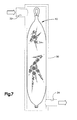
- FIGURE 7 shows the cartridge of FIGURE 1 indicated in a filter housing.
- the filter cartridge of the present disclosure is indicated generally at 10 and has a casing or sleeve 12 with an elongated tubular configuration which is filled with particulate or polymer material 14 with one end of the sleeve gathered to closure and banded with clamp band 16. The opposite end of the sleeve is gathered, closed, fused and subsequently folded over and banded with a clamp band 18 to form a loop 20 therein to facilitate removal of the cartridge from a filter housing.
- the exemplary version disclosed is formed of a tubular sleeve 22 having a nominal O.D. of about 78 mm and a cut length of about 610 mm.
- suitable monofilament polymer material may also be utilized for the woven mesh sleeve 12; and, other sizes may be employed if desired.
- the sleeve 12 is formed, as by a hot knife, cutting to length from a tubular woven mesh material 22 having a nominal O.D. of 78 mm and in the range of about 38 mm to 89 mm and a nominal wall thickness indicated by reference character "t" in FIG. 2 of about 0.635 mm and a nominal length denoted by reference character "I" in FIG. 2 of about 610 mm.
- the monofilament woven mesh sleeve having an initial nominal O.D. of about 38 mm is capable of expansion to a diameter in the range of about 38 mm to 89 mm.
- the particulate or granular polymer material is obtainable from AbTech Industries Inc., 4110 North Scottsdale Road, Suite 235, Scottsdale, AZ 85251, and is sold under the trade name SMART SPONGE® PLUS under Manufacturer's identification ACX-10-N-PLUS. In the present practice, it has been found satisfactory to coat the particulate polymer material with an organosilane antimicrobial agent chemically and permanently bound to the polymer surface for reducing coliform bacteria. However, it will be understood that other suitable particulate or granular polymer material may be employed in the cartridge of the present disclosure if desired.
- the method as practiced by initially cutting the length "L" of the sleeve tubing 22 such as by a using hot knife. They method then proceeds to gather to closure and band with the clamp band 16 one end of the tubular sleeving and heat fusing the end subsequent to banding, as shown in FIG. 3 , thereby forming a pocket within the sleeve tube 22.
- the opened end of the sleeve 22 is then fitted with a funnel such as funnel 24 and the particulate or granular polymer material 14 is then introduced into the sleeve pocket through the funnel as illustrated in FIG. 4 .
- the funnel 24 is removed; and, the remaining open end denoted by reference numeral 26 of the tubular sleeve is closed and fused as shown in FIG. 5 .
- the end 26 is folded over upon itself to form a loop 20 and the end is banded by clamp band 28 as shown in FIG. 6 to form the closed sleeve 12 and the completed cartridge 10.
- the cartridge 10 is shown as installed in a typical filter housing 30 as indicated in dashed outline and having an inlet 32 near one end of the cartridge 10 and an outlet proximate a distal end of the cartridge as denoted by reference numeral 34.
- the present disclosure describes a filter cartridge formed of monofilament woven polyethylene mesh sleeve with the ends closed and banded to contain within the sleeve particulate or granular polymer material which may be coated with an organosilane antimicrobial agent.
- the cartridge is adapted for insertion in a filter housing having an inlet near one end of the tubular cartridge sleeve and an outlet proximate the opposite end of the sleeve cartridge.
- the method includes closing, banding and fusing one end of a length of tubular woven mesh sleeve, filling the pocket formed thereby with particulate polymer material and closing, fusing and folding over the opposite end and banding the end to form a loop for facilitating removal of the cartridge from a filter housing.
- the cartridge is configured to closely fit the internal cavity of the chosen housing such that flow from the inlet into the cavity does not bypass the cartridge to the outlet.
Landscapes
- Engineering & Computer Science (AREA)
- Textile Engineering (AREA)
- Chemical & Material Sciences (AREA)
- Chemical Kinetics & Catalysis (AREA)
- Filtering Materials (AREA)
Abstract
Description
- This application is related to co-pending application of
Mark Anthony Quintel, Derek Ronald Thelen, Christopher Scott Rau and Richard Jacobs, Application No. 13/086,699, filed April 14, 2011 - The present disclosure relates to fluid filters and particularly filters of the type utilized for filtering waste water from a closed system such as a fire suppression sprinkler system or fire hydrants. Such systems are required to be drained and/or flushed periodically to remove sediments and rust to insure proper operation of the system when the need arises.
- Under current environmental regulations, wastewater drained from the aforesaid type fluid systems is required to be filtered of contaminants prior to discharge in drainage systems, for example a storm drain. Therefore, it has been required to provide a filtration unit attachable to the source of fluid, such as wastewater, to be drained at the location of connection to the system. Thus, it has been desired to provide a suitable filtration unit capable of being transported to the site. It has further been desired to have a filtration unit in which the filtering media can readily be replaced upon the media becoming saturated with contaminants and unable to provide the desired filtering action.
- Heretofore, filtration units of the type intended for portable use with replacement filtering elements have been somewhat complex and difficult to replenish with filtering media capable of providing the desired high degree of filtration. Furthermore, existing wastewater filtration units intended for transporting to a site or for installation in a stationary closed system have been of significant bulk or volume and weight as to render the usage thereof rather cumbersome and, in some applications, requiring more than one operator.
- Thus, it has been desired to provide a way or means of readily and easily replacing the filter media in a closed fluid filtration system to provide adequate filtering thereby enabling discharge of the fluid into a storm drain or other open body of liquid.
- The filter cartridge of the present disclosure employs a tubular sleeve formed of monofilament polyethylene woven mesh filled with particulate or granular polymer which may be in shredded form with the opposite ends of the sleeve closed and fused to retain the particulate or granular material therein. The cartridge is then in a form to be inserted in a housing having a fluid inlet near a proximal end of the cartridge and a fluid outlet proximate the distal end of the cartridge.
- The particulate or granular polymer material may be coated with an organosilane antimicrobial agent. In one disclosed version, the monofilament woven mesh sleeve is woven of monofilament of about 0.254 mm thickness with a tensile strength per ASTM D-2265 of about 7.5 pounds; and, the sleeve may have a tubular wall thickness of about 0.635 mm. The monofilament may have a specific gravity of about 1.38. The particulate or granular polymer material may have a specific gravity in the range of about 0.27 to 0.40.
- One exemplary version of the disclosed method includes cutting a monofilament polyethylene woven mesh sleeve having a tubular configuration to a desired length, closing and banding one end of the sleeve and fusing the banded end. The sleeve in the disclosed exemplary version has a nominal outside diameter (O.D.) of about 78 mm and is cut to a length of about 610 mm. The pocket formed by the closed end of the sleeve is then filled with the particulate or granular polymer material; and, the remaining open end is gathered, closed, fused and then folded over and banded to form a loop in the end thereof to facilitate removal of the cartridge thus formed from a filtration system housing.
-
FIGURE 1 is a side view of an exemplary version of the cartridge of the present disclosure with a portion of the outer sleeve broken away; -
FIGURE 2 is a side view of the cut length of tubular woven mesh sleeve for the cartridge ofFIGURE 1 ; -
FIGURE 3 is a view of the sleeve ofFIGURE 2 , with one end banded and fused; -
FIGURE 4 is a pictorial view showing filling of the sleeve ofFIGURE 3 ; -
FIGURE 5 is a view similar toFIGURE 3 showing the closure and forming of the remaining end of the sleeve after filtering ofFIGURE 4 ; -
FIGURE 6 shows the folding over and banding of the end ofFIGURE 5 ; and, -
FIGURE 7 shows the cartridge ofFIGURE 1 indicated in a filter housing. - Referring to
FIG. 1 , the filter cartridge of the present disclosure is indicated generally at 10 and has a casing orsleeve 12 with an elongated tubular configuration which is filled with particulate orpolymer material 14 with one end of the sleeve gathered to closure and banded withclamp band 16. The opposite end of the sleeve is gathered, closed, fused and subsequently folded over and banded with aclamp band 18 to form aloop 20 therein to facilitate removal of the cartridge from a filter housing. - In the present practice, it has been found satisfactory to utilize monofilament polyethylene terephthalate material for the woven mesh sleeve having a monofilament thickness of about 0.254 mm with a specific gravity of about 1.38 and a tensile strength per ASTM D-2265 of about 7.5 pounds. Referring to
FIG. 2 , the exemplary version disclosed is formed of atubular sleeve 22 having a nominal O.D. of about 78 mm and a cut length of about 610 mm. However, other suitable monofilament polymer material may also be utilized for thewoven mesh sleeve 12; and, other sizes may be employed if desired. - Referring to
FIG. 2 , in one version of the cartridge of the present disclosure, thesleeve 12 is formed, as by a hot knife, cutting to length from a tubularwoven mesh material 22 having a nominal O.D. of 78 mm and in the range of about 38 mm to 89 mm and a nominal wall thickness indicated by reference character "t" inFIG. 2 of about 0.635 mm and a nominal length denoted by reference character "I" inFIG. 2 of about 610 mm. In the present practice, the monofilament woven mesh sleeve having an initial nominal O.D. of about 38 mm is capable of expansion to a diameter in the range of about 38 mm to 89 mm. - The particulate or granular polymer material is obtainable from AbTech Industries Inc., 4110 North Scottsdale Road, Suite 235, Scottsdale, AZ 85251, and is sold under the trade name SMART SPONGE® PLUS under Manufacturer's identification ACX-10-N-PLUS. In the present practice, it has been found satisfactory to coat the particulate polymer material with an organosilane antimicrobial agent chemically and permanently bound to the polymer surface for reducing coliform bacteria. However, it will be understood that other suitable particulate or granular polymer material may be employed in the cartridge of the present disclosure if desired.
- Referring to
FIG. 2 , the method as practiced by initially cutting the length "L" of thesleeve tubing 22 such as by a using hot knife. They method then proceeds to gather to closure and band with theclamp band 16 one end of the tubular sleeving and heat fusing the end subsequent to banding, as shown inFIG. 3 , thereby forming a pocket within thesleeve tube 22. - Referring to
FIG. 4 , the opened end of thesleeve 22 is then fitted with a funnel such asfunnel 24 and the particulate orgranular polymer material 14 is then introduced into the sleeve pocket through the funnel as illustrated inFIG. 4 . Upon completion of the fill, thefunnel 24 is removed; and, the remaining open end denoted byreference numeral 26 of the tubular sleeve is closed and fused as shown inFIG. 5 . - Subsequently, the
end 26 is folded over upon itself to form aloop 20 and the end is banded by clamp band 28 as shown inFIG. 6 to form the closedsleeve 12 and the completedcartridge 10. Referring toFIG. 7 , thecartridge 10 is shown as installed in atypical filter housing 30 as indicated in dashed outline and having aninlet 32 near one end of thecartridge 10 and an outlet proximate a distal end of the cartridge as denoted byreference numeral 34. - The present disclosure describes a filter cartridge formed of monofilament woven polyethylene mesh sleeve with the ends closed and banded to contain within the sleeve particulate or granular polymer material which may be coated with an organosilane antimicrobial agent. The cartridge is adapted for insertion in a filter housing having an inlet near one end of the tubular cartridge sleeve and an outlet proximate the opposite end of the sleeve cartridge. The method includes closing, banding and fusing one end of a length of tubular woven mesh sleeve, filling the pocket formed thereby with particulate polymer material and closing, fusing and folding over the opposite end and banding the end to form a loop for facilitating removal of the cartridge from a filter housing. The cartridge is configured to closely fit the internal cavity of the chosen housing such that flow from the inlet into the cavity does not bypass the cartridge to the outlet.
- The exemplary embodiment has been described with reference to the exemplary disclosed embodiment. Obviously, modifications and alterations will occur to others upon reading and understanding the preceding detailed description. It is intended that the exemplary embodiment be construed as including all such modifications and alterations insofar as they come within the scope of the appended claims or the equivalents thereof.
-
- 1. A fluid filter cartridge for use in a filter housing comprising:
- (a) a tubular sleeve of monofilament woven mesh polyethylene material having the opposite ends of the sleeve sequentially gathered to closure, banded and fused; and,
- (b) a filler of particulate polymer material dispersed in the sleeve.
- 2. The cartridge of 1, wherein the particulate polymer material has a specific gravity in the range of about 0.27-0.40.
- 3. The cartridge of 1, wherein the filler includes an antimicrobial agent chemically and permanently bound.
- 4. The cartridge of 1, wherein the sleeve is formed of woven polyethylene terephthalate mesh material.
- 5. The cartridge of 1, wherein the sleeve is formed of woven monofilament of about 0.01 inches (0.254 mm) thickness.
- 6. The cartridge of 1, wherein the monofilament has a tensile strength per ASTM-D-2265 of 7.5 Ibs.
- 7. The cartridge of 1, wherein the sleeve has a wall thickness of about 0.025 inches (0.635 mm).
- 8. The cartridge of 1, wherein the particulate polymer is treated with an organosilane antimicrobial agent.
- 9. The cartridge of 1, wherein the sleeve is expandable from about 38 mm O.D. to about 89 mm O.D.
- 10. The cartridge of 1, wherein the monofilament has a specific gravity of about 1.38.
- 11. The cartridge of 1, wherein the sleeve is filled with shredded polymer material
- 12. A method of making a fluid filter cartridge for use in a filter housing comprising:
- (a) forming a tubular sleeve of monofilament woven polyethylene mesh material;
- (b) gathering to closure, banding and fusing an end of the sleeve and forming a pocket;
- (c) filling the pocket with particulate polymeric material;
- (d) gathering to closure and fusing an end of the sleeve opposite the one end; and,
- (e) folding over and banding the opposite end.
- 13. The method defined in 12, wherein the step of forming a sleeve includes forming the sleeve of polyethylene terephthalate woven mesh.
- 14. The method defined in 12, wherein the step of forming a sleeve includes forming a sleeve of woven monofilament of about 0.01 inches (0.254 mm) thickness.
- 15. The method defined in 12, wherein the step of forming a sleeve includes forming of woven monofilament having a tensile strength per ASTM-D-2265 of 7.5 lbs.
- 16. The method defined in 12, wherein the step of forming a tubular sleeve includes forming a sleeve having a wall thickness of about 0.025 inches (0.635 mm).
- 17. The method defined in 12, wherein the step of filling the pocket includes filling with particulate polymer material treated with organosilane antimicrobial agent.
Claims (10)
- A fluid filter cartridge (10) for use in a filter housing (30) comprising:(a) a tubular sleeve (12) of monofilament woven mesh polyethylene material having the opposite ends of the sleeve sequentially gathered to closure, banded (16) (18) and fused; and,(b) a filler of particulate polymer material (14) dispersed in the sleeve.
- The cartridge of claim 1; wherein the particulate polymer material has a specific gravity in the range of about 0.27-0.40.
- The cartridge of claim 1, wherein the filler includes an antimicrobial agent chemically and permanently bound.
- The cartridge of claim 1, wherein the sleeve is formed of woven polyethylene terephthalate mesh material.
- The cartridge of claim 1, wherein the monofilament has a tensile strength per ASTM-D-2265 of 7.5 Ibs.
- The cartridge of claim 1, wherein the sleeve has a wall thickness of about 0.025 inches (0.635 mm).
- A method of making a fluid filter cartridge (10) for use in a filter housing (30) comprising:(a) forming a tubular sleeve (12) of monofilament woven polyethylene mesh material;(b) gathering to closure, banding (16) and fusing an end of the sleeve and forming a pocket;(c) filling the pocket with particulate polymeric material (14);(d) gathering to closure and fusing an end of the sleeve opposite the one end; and,(e) folding over and banding (18) the opposite end.
- The method defined in claim 7, wherein the step of forming a sleeve includes forming the sleeve of polyethylene terephthalate woven mesh.
- The method defined in claim 7, wherein the step of forming a sleeve includes forming a sleeve of woven monofilament of about 0.01 inches (0.254 mm) thickness.
- The method defined in claim 7, wherein the step of forming a sleeve includes forming of woven monofilament having a tensile strength per ASTM-D-2265 of 7.5 lbs.
Applications Claiming Priority (1)
| Application Number | Priority Date | Filing Date | Title |
|---|---|---|---|
| US13/086,756 US20120261329A1 (en) | 2011-04-14 | 2011-04-14 | Filter cartridge for use in a fluid filter housing and method of making same |
Publications (1)
| Publication Number | Publication Date |
|---|---|
| EP2514502A1 true EP2514502A1 (en) | 2012-10-24 |
Family
ID=45999542
Family Applications (1)
| Application Number | Title | Priority Date | Filing Date |
|---|---|---|---|
| EP12002609A Withdrawn EP2514502A1 (en) | 2011-04-14 | 2012-04-13 | Filter cartridge for use in a fluid filter housing and method of making same |
Country Status (2)
| Country | Link |
|---|---|
| US (1) | US20120261329A1 (en) |
| EP (1) | EP2514502A1 (en) |
Families Citing this family (13)
| Publication number | Priority date | Publication date | Assignee | Title |
|---|---|---|---|---|
| USD742997S1 (en) | 2014-04-10 | 2015-11-10 | Unger Marketing International, Llc | Water purification media device |
| US11911720B2 (en) | 2014-04-10 | 2024-02-27 | Unger Marketing International, Llc | Fluid purification device |
| EP3696146B1 (en) | 2014-04-10 | 2022-09-07 | Unger Marketing International, LLC | Filter bag pure water systems |
| USD740915S1 (en) | 2014-04-10 | 2015-10-13 | Unger Marketing International, Llc | Water purification device |
| US11148082B2 (en) | 2015-04-10 | 2021-10-19 | Unger Marketing International, Llc | Fluid purification device |
| USD849886S1 (en) | 2017-08-28 | 2019-05-28 | Unger Marketing International, Llc | Water purification device |
| US11154800B2 (en) | 2015-04-10 | 2021-10-26 | Unger Marketing International, Llc | Fluid purification device |
| USD907742S1 (en) | 2018-03-07 | 2021-01-12 | Unger Marketing International, Llc | Water purification media device |
| USD958928S1 (en) | 2018-11-01 | 2022-07-26 | Unger Marketing International, Llc | Water purification media device |
| USD913413S1 (en) | 2019-06-04 | 2021-03-16 | Unger Marketing International, Llc | Water purification media device |
| CA3116876C (en) * | 2020-04-29 | 2023-01-03 | Canadian National Railway Company | Device for dewatering and method of making same |
| ES2924777A1 (en) * | 2021-03-26 | 2022-10-10 | Univ Catalunya Politecnica | DEVICE FOR RETAINING TEXTILE MICROFIBERS AND METHOD FOR OBTAINING A PRODUCT MADE FROM A WASTE GENERATED BY TEXTILE ELEMENTS |
| US11969674B2 (en) * | 2022-06-03 | 2024-04-30 | Todd Ewing | Liquid filtering bag |
Citations (3)
| Publication number | Priority date | Publication date | Assignee | Title |
|---|---|---|---|---|
| EP1553113A1 (en) * | 2002-06-17 | 2005-07-13 | ASAHI MEDICAL Co., Ltd. | Biocompatible polymer and filter for selectively eliminating leucocytes using the same |
| WO2008010878A2 (en) * | 2006-07-19 | 2008-01-24 | Denny Hastings Flp 14 | Water filtration and erosion control system and method |
| US20090114597A1 (en) * | 2007-11-05 | 2009-05-07 | Cronia Forrest E | Geotextile composite for filtration of contaminated liquids and sediments and methods of using same |
Family Cites Families (8)
| Publication number | Priority date | Publication date | Assignee | Title |
|---|---|---|---|---|
| US3499259A (en) * | 1966-02-09 | 1970-03-10 | Rheem Mfg Co | Packaging apparatus and method |
| US3540184A (en) * | 1967-08-28 | 1970-11-17 | Bemis Co Inc | Packaging method |
| US3780488A (en) * | 1969-11-20 | 1973-12-25 | Dow Chemical Co | Closure for film packages and method of making same |
| US4071063A (en) * | 1976-06-17 | 1978-01-31 | Swift & Company | Non-releasable hand grip for package or loop handle of a bag |
| GB2267819B (en) * | 1992-06-18 | 1995-08-16 | R R Donnelley And Sons Company | Liquid absorbing and retaining apparatus |
| US6099723A (en) * | 1997-06-06 | 2000-08-08 | Abtech Industries, Inc. | Catchbasin systems for filtering hydrocarbon spills |
| US7459074B1 (en) * | 2007-07-27 | 2008-12-02 | Sanchez Robert M | Waste water filtering system |
| US8323493B2 (en) * | 2011-04-14 | 2012-12-04 | Eaton Corporation | Fluid filter |
-
2011
- 2011-04-14 US US13/086,756 patent/US20120261329A1/en not_active Abandoned
-
2012
- 2012-04-13 EP EP12002609A patent/EP2514502A1/en not_active Withdrawn
Patent Citations (3)
| Publication number | Priority date | Publication date | Assignee | Title |
|---|---|---|---|---|
| EP1553113A1 (en) * | 2002-06-17 | 2005-07-13 | ASAHI MEDICAL Co., Ltd. | Biocompatible polymer and filter for selectively eliminating leucocytes using the same |
| WO2008010878A2 (en) * | 2006-07-19 | 2008-01-24 | Denny Hastings Flp 14 | Water filtration and erosion control system and method |
| US20090114597A1 (en) * | 2007-11-05 | 2009-05-07 | Cronia Forrest E | Geotextile composite for filtration of contaminated liquids and sediments and methods of using same |
Also Published As
| Publication number | Publication date |
|---|---|
| US20120261329A1 (en) | 2012-10-18 |
Similar Documents
| Publication | Publication Date | Title |
|---|---|---|
| EP2514502A1 (en) | Filter cartridge for use in a fluid filter housing and method of making same | |
| CN104707373B (en) | Filter | |
| EP2510993A1 (en) | Fluid filter and method of filtering | |
| US7165913B2 (en) | Trench drain filter assembly | |
| US6048456A (en) | Water filter housing | |
| US20170246567A1 (en) | Filtering Pump System | |
| US8741137B2 (en) | Filtering methods and configurations | |
| WO2007145947A2 (en) | High back pressure filter for removing non-water component(s) from water, and methodology | |
| CN103459819B (en) | a valve | |
| US20110031173A1 (en) | Cylindrical Inline Fluids Filter | |
| US20190343074A1 (en) | Drinking bowl for domestic animals | |
| ATE504345T1 (en) | FILTER DEVICE | |
| US6841007B1 (en) | Method for pipeline filtration | |
| JP2012528276A (en) | How to remove air from the filter | |
| CN101479015B (en) | Water purifier system and filter element for the system | |
| JP5108347B2 (en) | Flexible bowl-shaped resin pipe filter | |
| US20170173500A1 (en) | Filter with flexible ribs | |
| KR20130035546A (en) | Direct type water purifier | |
| US7438820B1 (en) | Waste water filtering method and system | |
| IL229494A (en) | Internal pod for gauze filter of water filter | |
| KR101764414B1 (en) | Installation method of detachable residual water drain module | |
| CA2598345C (en) | Arrangement related to a separator for the cleaning of such separator | |
| EP3523249B1 (en) | Device for water purification | |
| JP2007009328A (en) | Corrosion inhibitor dispensing apparatus and method | |
| KR101518973B1 (en) | Equipped with a filter cartridge drain sewage |
Legal Events
| Date | Code | Title | Description |
|---|---|---|---|
| PUAI | Public reference made under article 153(3) epc to a published international application that has entered the european phase |
Free format text: ORIGINAL CODE: 0009012 |
|
| AK | Designated contracting states |
Kind code of ref document: A1 Designated state(s): AL AT BE BG CH CY CZ DE DK EE ES FI FR GB GR HR HU IE IS IT LI LT LU LV MC MK MT NL NO PL PT RO RS SE SI SK SM TR |
|
| AX | Request for extension of the european patent |
Extension state: BA ME |
|
| 17P | Request for examination filed |
Effective date: 20130218 |
|
| GRAP | Despatch of communication of intention to grant a patent |
Free format text: ORIGINAL CODE: EPIDOSNIGR1 |
|
| INTG | Intention to grant announced |
Effective date: 20141022 |
|
| STAA | Information on the status of an ep patent application or granted ep patent |
Free format text: STATUS: THE APPLICATION IS DEEMED TO BE WITHDRAWN |
|
| 18D | Application deemed to be withdrawn |
Effective date: 20150303 |