EP2514452A1 - Needle device - Google Patents
Needle device Download PDFInfo
- Publication number
- EP2514452A1 EP2514452A1 EP10837401A EP10837401A EP2514452A1 EP 2514452 A1 EP2514452 A1 EP 2514452A1 EP 10837401 A EP10837401 A EP 10837401A EP 10837401 A EP10837401 A EP 10837401A EP 2514452 A1 EP2514452 A1 EP 2514452A1
- Authority
- EP
- European Patent Office
- Prior art keywords
- inner hub
- hole
- hub
- needle
- opening
- Prior art date
- Legal status (The legal status is an assumption and is not a legal conclusion. Google has not performed a legal analysis and makes no representation as to the accuracy of the status listed.)
- Granted
Links
- 239000007788 liquid Substances 0.000 claims abstract description 104
- 230000000149 penetrating effect Effects 0.000 claims abstract description 9
- 230000037452 priming Effects 0.000 description 16
- 239000000243 solution Substances 0.000 description 12
- 238000003780 insertion Methods 0.000 description 10
- 230000037431 insertion Effects 0.000 description 10
- 239000003814 drug Substances 0.000 description 9
- 229940079593 drug Drugs 0.000 description 9
- -1 polypropylene Polymers 0.000 description 8
- 230000001737 promoting effect Effects 0.000 description 7
- 210000004204 blood vessel Anatomy 0.000 description 6
- 230000000052 comparative effect Effects 0.000 description 6
- 239000002504 physiological saline solution Substances 0.000 description 5
- 239000004743 Polypropylene Substances 0.000 description 4
- 239000008280 blood Substances 0.000 description 4
- 210000004369 blood Anatomy 0.000 description 4
- 238000001802 infusion Methods 0.000 description 4
- 230000035515 penetration Effects 0.000 description 4
- 229920000515 polycarbonate Polymers 0.000 description 4
- 239000004417 polycarbonate Substances 0.000 description 4
- 229920001155 polypropylene Polymers 0.000 description 4
- 235000015097 nutrients Nutrition 0.000 description 3
- 239000000853 adhesive Substances 0.000 description 2
- 230000001070 adhesive effect Effects 0.000 description 2
- 230000015572 biosynthetic process Effects 0.000 description 2
- 229920002313 fluoropolymer Polymers 0.000 description 2
- 239000002184 metal Substances 0.000 description 2
- 229920001343 polytetrafluoroethylene Polymers 0.000 description 2
- 239000004810 polytetrafluoroethylene Substances 0.000 description 2
- 229920003225 polyurethane elastomer Polymers 0.000 description 2
- 238000007789 sealing Methods 0.000 description 2
- 230000000694 effects Effects 0.000 description 1
- 238000004519 manufacturing process Methods 0.000 description 1
- 238000000034 method Methods 0.000 description 1
- 238000012986 modification Methods 0.000 description 1
- 230000004048 modification Effects 0.000 description 1
Images









Classifications
-
- A—HUMAN NECESSITIES
- A61—MEDICAL OR VETERINARY SCIENCE; HYGIENE
- A61M—DEVICES FOR INTRODUCING MEDIA INTO, OR ONTO, THE BODY; DEVICES FOR TRANSDUCING BODY MEDIA OR FOR TAKING MEDIA FROM THE BODY; DEVICES FOR PRODUCING OR ENDING SLEEP OR STUPOR
- A61M5/00—Devices for bringing media into the body in a subcutaneous, intra-vascular or intramuscular way; Accessories therefor, e.g. filling or cleaning devices, arm-rests
- A61M5/36—Devices for bringing media into the body in a subcutaneous, intra-vascular or intramuscular way; Accessories therefor, e.g. filling or cleaning devices, arm-rests with means for eliminating or preventing injection or infusion of air into body
-
- A—HUMAN NECESSITIES
- A61—MEDICAL OR VETERINARY SCIENCE; HYGIENE
- A61M—DEVICES FOR INTRODUCING MEDIA INTO, OR ONTO, THE BODY; DEVICES FOR TRANSDUCING BODY MEDIA OR FOR TAKING MEDIA FROM THE BODY; DEVICES FOR PRODUCING OR ENDING SLEEP OR STUPOR
- A61M5/00—Devices for bringing media into the body in a subcutaneous, intra-vascular or intramuscular way; Accessories therefor, e.g. filling or cleaning devices, arm-rests
- A61M5/178—Syringes
- A61M5/31—Details
- A61M5/32—Needles; Details of needles pertaining to their connection with syringe or hub; Accessories for bringing the needle into, or holding the needle on, the body; Devices for protection of needles
- A61M5/3293—Needles; Details of needles pertaining to their connection with syringe or hub; Accessories for bringing the needle into, or holding the needle on, the body; Devices for protection of needles characterised by features of the needle hub
-
- A—HUMAN NECESSITIES
- A61—MEDICAL OR VETERINARY SCIENCE; HYGIENE
- A61M—DEVICES FOR INTRODUCING MEDIA INTO, OR ONTO, THE BODY; DEVICES FOR TRANSDUCING BODY MEDIA OR FOR TAKING MEDIA FROM THE BODY; DEVICES FOR PRODUCING OR ENDING SLEEP OR STUPOR
- A61M5/00—Devices for bringing media into the body in a subcutaneous, intra-vascular or intramuscular way; Accessories therefor, e.g. filling or cleaning devices, arm-rests
- A61M5/178—Syringes
- A61M5/31—Details
- A61M5/32—Needles; Details of needles pertaining to their connection with syringe or hub; Accessories for bringing the needle into, or holding the needle on, the body; Devices for protection of needles
- A61M5/34—Constructions for connecting the needle, e.g. to syringe nozzle or needle hub
-
- A—HUMAN NECESSITIES
- A61—MEDICAL OR VETERINARY SCIENCE; HYGIENE
- A61M—DEVICES FOR INTRODUCING MEDIA INTO, OR ONTO, THE BODY; DEVICES FOR TRANSDUCING BODY MEDIA OR FOR TAKING MEDIA FROM THE BODY; DEVICES FOR PRODUCING OR ENDING SLEEP OR STUPOR
- A61M25/00—Catheters; Hollow probes
- A61M25/01—Introducing, guiding, advancing, emplacing or holding catheters
- A61M25/06—Body-piercing guide needles or the like
- A61M25/0612—Devices for protecting the needle; Devices to help insertion of the needle, e.g. wings or holders
- A61M25/0631—Devices for protecting the needle; Devices to help insertion of the needle, e.g. wings or holders having means for fully covering the needle after its withdrawal, e.g. needle being withdrawn inside the handle or a cover being advanced over the needle
Definitions
- the present invention relates to a needle device in which an inner hub with a needle integrated therewith is provided in a cylindrical body.
- a known indwelling needle device is one in which a needle portion projecting from a tip of a cylindrical body has a double structure including a soft outer needle and a hard inner needle (see Patent Documents 1 and 2).
- the hard inner needle is integrated with the inner hub to which a tube is connected. By pulling the tube, the inner hub is moved, so that the hard inner needle integrated with the inner hub is pulled into the cylindrical body.
- a drug solution etc. is supplied through the tube to the inner hub connected to the tube and then passed through the soft outer needle before being administered into a patient.
- the drug solution etc. is administered, if air is present in the indwelling needle device, the air enters a blood vessel along with the drug solution etc.
- the indwelling needle device is filled with a liquid, such as physiological saline, a nutrient solution, etc. This operation is called priming.
- the liquid injected into the indwelling needle device is discharged through the inner hub.
- the injected liquid temporarily flows into the inner hub, flows out of the inner hub through a hole formed in the inner hub, and passes through a gap between an outer circumferential surface of the inner hub and the cylindrical body, before reaching the outer needle.
- the liquid may not reach or spread sufficiently over the outer circumferential surface of the inner hub, and therefore, air bubbles may continue to remain on the outer circumferential surface of the inner hub.
- the present invention has been made to solve the above conventional problem. It is an object of the present invention to provide a needle device that can prevent air bubbles from remaining on the outer circumferential surface of the inner hub.
- a first needle device includes an inner hub with a needle attached to a tip thereof, and a cylindrical body housing the inner hub.
- the inner hub includes a through-hole penetrating the inner hub in a radial direction of the inner hub, and a recessed portion formed in an outer circumferential surface of the inner hub. An opening of the through-hole and the recessed portion are connected together in a circumferential direction of the inner hub.
- a second needle device includes an inner hub with a needle attached to a tip thereof, and a cylindrical body housing the inner hub.
- the inner hub includes a through-hole penetrating the inner hub in a radial direction of the inner hub, and a protrusion formed between an opening of the through-hole and the tip of the inner hub and protruding from an outer circumferential surface of the inner hub.
- air bubbles can be prevented from remaining on the outer circumferential surface of the inner hub.
- the recessed portion connected to the opening of the through-hole in the circumferential direction of the inner hub is formed in the outer circumferential surface of the inner hub. Therefore, the flow of a liquid flowing out from the opening of the through-hole is limited so that the liquid flows along the recessed portion, whereby the flow of the liquid moving in the circumferential direction of the inner hub can be promoted. As a result, the removal of air bubbles in the circumferential direction of the inner hub is promoted. Therefore, according to the present invention, when a liquid is injected into the needle device in the priming operation, air can be replaced reliably with the liquid, whereby air bubbles can be prevented from remaining on the outer circumferential surface of the inner hub.
- the recessed portion is preferably arranged to guide a liquid flowing out from the opening of the through-hole in the circumferential direction of the inner hub.
- the opening of the through-hole is preferably interposed between the recessed portions in the circumferential direction of the inner hub. This configuration is advantageous for promoting the removal of air bubbles in the circumferential direction of the inner hub.
- the recessed portions are preferably separated from each other by a separator surface serving as a boundary, and preferably include a portion whose depth becomes gradually shallower in a direction from the opening of the through-hole to the separator surface.
- This configuration allows air bubbles to move more easily up onto the top of the separator surface along with the liquid and then flow toward the tip of the inner hub.
- this configuration is advantageous for promoting the removal of air bubbles.
- the recessed portion preferably includes a portion extending in an axial direction of the inner hub. This configuration is advantageous for promoting the removal of air bubbles in the axial direction of the inner hub.
- the width of the recessed portion is preferably smaller than or equal to one half of the length of the opening of the through-hole in an axial direction of the inner hub.
- the protrusion is provided on the inner hub. Therefore, a liquid flowing out from the opening of the through-hole formed in the inner hub is divided into streams moving on both sides of the protrusion, whereby the flow of the liquid moving in the circumferential direction of the inner hub can be promoted. As a result, the removal of air bubbles in the circumferential direction of the inner hub is promoted. Therefore, according to the present invention, when a liquid is injected into the needle device in the priming operation, air can be reliably replaced with the liquid, whereby air bubbles can be prevented from remaining on the outer circumferential surface of the inner hub.
- the inner hub preferably includes a recessed portion at which the outer circumferential surface of the inner hub is recessed inward, and the protrusion preferably protrudes from the recessed portion. With this configuration, the protrusion can be formed while an outer diameter dimension of the inner hub is maintained.
- the protrusion is preferably arranged to guide a liquid flowing out from the opening of the through-hole in a circumferential direction of the inner hub.
- a wall surface of the protrusion preferably faces the opening of the through-hole.
- the opening of the through-hole preferably is interposed between the recessed portions in a circumferential direction of the inner hub.
- the recessed portion plays the role of a groove that guides the flow of the liquid in the circumferential direction of the inner hub.
- this configuration is advantageous for promoting the flow of the liquid moving in the circumferential direction of the inner hub.
- a dimension of a gap between the protrusion and the opening of the through-hole is preferably smaller than or equal to one half of a shortest distance between the opening of the through-hole and the tip of the inner hub.
- side surfaces on both sides of the protrusion preferably are arranged to form a substantially V shape, and the width of the protrusion preferably becomes gradually wider toward the through-hole.
- the protrusion has a sharp tapered tip portion, whereby air bubbles can be prevented from remaining at the tip portion of the protrusion.
- the present invention relates to a needle device.
- the needle device of the present invention will be described using an example medical indwelling needle device whose needle portion has a double structure including an outer needle and an inner needle.
- Such an indwelling needle device is used for infusion and blood transfusion. Infusion and blood transfusion are performed while only the soft outer needle is left at an insertion site.
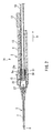
- FIG. 1 is a perspective view of an external appearance of an indwelling needle device 1A according to a first embodiment of the present invention.
- FIG. 2 is a cross-sectional view of the indwelling needle device 1A of FIG. 1 which is taken along a longitudinal direction thereof.
- FIG. 3 is an enlarged view of a tip portion of the indwelling needle device 1A of FIG. 2 .
- FIG. 4 is a cross-sectional view showing a state in which an inner needle 8, which was in the state of FIG. 2 , has been pulled into a shield cylinder 4.
- the indwelling needle device 1A includes a cylindrical body 2 in which an outer hub 5 is attached to a tip of the shield cylinder 4.
- the body 2 includes a needle portion 3 ( FIG. 2 ) at a tip portion thereof.
- a cap 6 is attached to the needle portion 3.
- the shield cylinder 4 and the outer hub 5 are made of, for example, polycarbonate, polypropylene, or the like.
- the needle portion 3 has a double structure in which the hard inner needle 8 made of a metal is inserted in a hollow portion of a tube-like soft outer needle 7.
- the outer needle 7 is fixed to the outer hub 5, and the inner needle 8 is fixed to an inner hub 9.
- the inner hub 9 is made of, for example, polycarbonate, polypropylene, or the like.
- the outer needle 7 is made of, for example, polyurethane elastomer, fluoroplastic such as polytetrafluoroethylene, or the like.
- the inner needle 8 is inserted in a hole 27 of the inner hub 9. By applying an adhesive to an end portion 27a of the hole 27, the inner needle 8 can be fixed to the inner hub 9.
- the inner needle 8 projects into a through-hole 22. If the amount by which the inner needle 8 protrudes is set to be sufficiently large, even when the projecting amount of the inner needle 8 varies during manufacture, the inner needle 8 is allowed to project into the through-hole 22. For example, as shown in FIGS. 6 and 7 described below, the length of the through-hole 22 in an axial direction of the inner hub 9 is set to be long enough to ensure a sufficient projecting amount of the inner needle 8 into the through-hole 22.
- the inner needle 8 may be fixed to the inner hub 9 without causing the inner needle 8 to project into the through-hole 22.
- the inner hub 9 is housed in the body 2 and can be moved in the shield cylinder 4 in an axial direction of the shield cylinder 4.
- a sealing O-ring 15 is attached to the inner hub 9.
- a tube 10 is connected to a pipe-like portion 20 at a rear end of the inner hub 9 (see FIG. 5 ).
- the inner hub 9 is moved in the shield cylinder 4 in the direction indicated by the arrow "a.”
- the inner needle 8 integrated with the inner hub 9 is pulled into the shield cylinder 4 as shown in FIG. 4 .
- a ring portion 16 is attached to the shield cylinder 4, surrounding an outer circumference of the shield cylinder 4.
- a pair of wing portions 17 are integrated with the ring portion 16.
- a hub movement limiting member 11 is attached removably to the shield cylinder 4.
- the hub movement limiting member 11 includes a pair of cantilever portions 12. In FIG. 1 , although only one of the pair of cantilever portions 12 is shown, the pair of cantilever portions 12 are provided so as to sandwich the shield cylinder 4.
- a stopper 13 is integrated with the hub movement limiting member 11.
- the stopper 13 is inserted in the shield cylinder 4, and a tip 13a of the stopper 13 abuts a rear end surface 9a of the inner hub 9.
- the soft outer needle 7 is also inserted.
- the inner needle 8 and the outer needle 7 are inserted, if the cantilever portions 12 are released and the tube 10 is pulled in the direction indicated by the arrow "a," the inner needle 8 integrated with the inner hub 9 is pulled into the shield cylinder 4 as shown in FIG. 4 .
- the soft outer needle 7 is left at the insertion site. Therefore, even when the patient moves, pain at the insertion site can be relieved, and damage to a blood vessel can be avoided.
- a liquid such as a drug solution etc. to be administered to a patient is supplied from the tube 10 to the inner hub 9.
- the inner hub 9 includes a flow path 21 extending along the axial direction of the inner hub 9, and the through-hole 22 penetrating the inner hub 9 in a radial direction thereof.
- the flow path 21 and the through-hole 22 are connected together.
- the liquid supplied to the inner hub 9 passes through the flow path 21 and the through-hole 22 before flowing out of the inner hub 9.
- the liquid flowing out of the inner hub 9 passes through the body 2 to reach the hollow portion of the outer needle 7 before being administered to the patient's body.
- the indwelling needle device 1A when a drug solution etc. is administered, if air is present in the indwelling needle device 1A, the air enters a blood vessel along with the drug solution etc. Therefore, prior to insertion, the indwelling needle device 1A is filled with a liquid, such as physiological saline, a nutrient solution, etc. This operation is called priming.
- a liquid such as physiological saline, a nutrient solution, etc. This operation is called priming.
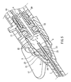
- FIG. 5 is an enlarged cross-sectional view of the vicinity of the inner hub 9 in FIG. 2 .
- FIG. 5 shows a cross-section of the inner hub 9 which is taken along a penetration direction of the through-hole 22.
- FIG. 6 is an enlarged cross-sectional view of the vicinity of the inner hub 9 which is taken along a direction perpendicular to the cross-section direction of FIG. 5 .
- FIG. 6 shows a cross-section of the inner hub 9 taken along the radial direction of the through-hole 22.
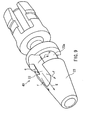
- FIG. 7 is an enlarged perspective view of the inner hub 9.
- the priming operation is performed while the inner needle 8 projects from the outer needle 7 as shown in FIG. 2 .
- a liquid such as physiological saline etc. is supplied from the tube 10 toward the inner hub 9 (in a direction indicated by an arrow "b").
- the liquid supplied to the inner hub 9 passes through the flow path 21 to flow into the through-hole 22.
- a portion of the liquid flowing into the through-hole 22 flows toward the outer circumferential surface of the inner hub 9, i.e., openings at both ends of the through-hole 22 (in directions indicated by arrows "c").
- Another portion of the liquid flowing into the through-hole 22 flows toward the inside of the inner needle 8 (in a direction indicated by an arrow "d").
- FIG. 7 is an enlarged perspective view of the inner hub 9.
- Recessed portions 23a in which the outer circumferential surface 23 of the inner hub 9 is recessed inward are formed in the outer circumferential surface 23.
- the recessed portions 23a are connected to the openings of the through-hole 22.
- the through-hole 22 is interposed between the recessed portions 23a in a circumferential direction of the inner hub 9.
- the recessed portions 23a are separated by separator surfaces 23b serving as boundaries.
- FIG. 7 shows a portion of the outer circumferential surface of the inner hub 9. Similar to FIG. 7 , recessed portions 23a are formed on a side (on the back side of the drawing sheet) on which the other opening of the through-hole 22 is provided, with the through-hole 22 being interposed between the recessed portions 23a in the circumferential direction of the inner hub 9.
- the recessed portions 23a connected to one opening of the through-hole 22 and the recessed portions 23a connected to the other opening of the through-hole 22 are separated from each other by a pair of the separator surfaces 23b. Therefore, the recessed portions 23 are not continuous in the circumferential direction.
- the recessed portions 23a are separated from each other by the separator surfaces 23b serving as boundaries.
- the depth of the recessed portion 23a becomes gradually shallower in a direction from the opening of the through-hole 22 to the separator surface 23b.
- the separator surface 23b is closer to the inner circumferential surface of the outer hub 5 than the recessed portion 23a is, but is not in complete contact therewith (see FIG. 6 ). Therefore, a gap 30 is formed between the separator surface 23b and the inner circumferential surface of the outer hub 5. Therefore, the liquid flow indicated by the arrow "e" of FIG. 7 moves up onto the separator surface 23b. After reaching the separator surface 23b, the liquid flows in the gap 30 toward the tip 26 of the inner hub 9.
- FIGS. 5 and 6 show the outer circumferential surface 23 of the inner hub 9 in a portion in which the recessed portion 23a is not formed.
- the outer circumferential surface 23 of the inner hub 9 shown in FIGS. 5 and 6 is close to the inner circumferential surface of the outer hub 5, but is not in complete contact therewith. Therefore, a gap 31 is formed between the outer circumferential surface 23 of the inner hub 9 and the inner circumferential surface of the outer hub 5. Therefore, the liquid indicated by the arrows "f" and “g” of FIG. 7 flows in the gap 31 ( FIGS. 5 and 6 ) toward the tip 26 of the inner hub 9.
- the liquid flowing out of the through-hole 22 generally moves in the axial direction of the inner hub 9 toward the tip 26 of the inner hub 9.
- the recessed portion 23a limits the flow of the liquid, and therefore, the flow of the liquid moving along the circumferential direction of the inner hub 9 also is promoted.
- the liquid which has reached the tip 26 of the inner hub 9 further moves toward the inside of the outer needle 7.
- the vicinity of the tip 26 of the inner hub 9 is not in complete contact with the inner circumferential surface of the outer hub 5, and therefore, a gap 33 is formed therebetween.
- a gap 34 is also formed between the hole of the outer hub 5 and the inner needle 8.
- a gap 35 is also formed between the inner circumferential surface of the outer needle 7 and the outer circumferential surface of the inner needle 8.
- the liquid flowing in the gap 31 toward the tip 26 of the inner hub 9 passes through the gap 33, the gap 34, and the gap 35 and then flows out from the tip of the outer needle 7 (an arrow "h").
- the liquid moving in the direction indicated by the arrow “d” of FIG. 5 passes through the hollow portion of the inner needle 8 and then flows out from the tip of the inner needle 8 as indicated by an arrow "i” of FIG. 3 .
- the space and the gaps located between the through-hole 22 and the tips of the inner needle 8 and the outer needle 7 are filled with the liquid, i.e., air is removed from the space and the gaps.
- FIG. 8 is a perspective view of an inner hub 100 according to the comparative example.
- a through-hole 102 is formed in an even outer circumferential surface 101 of the inner hub 100, penetrating therethrough in a radial direction.
- the recessed portion 23a is not formed in the outer circumferential surface 101 of the inner hub 100.
- a flow (an arrow "m") in a circumferential direction of the inner hub 100 is weak. Therefore, it gradually becomes more difficult for the liquid to reach a portion which is located farther away from the opening of the through-hole 102 in the circumferential direction of the inner hub 100. Therefore, air bubbles are more likely to remain at a portion located farther away from the opening of the through-hole 102 in the circumferential direction of the inner hub 100.
- the formation of the recessed portion 23a allows the liquid flowing out from the opening of the through-hole 22 to divide into streams moving on both sides in the circumferential direction of the through-hole 22, whereby the flow moving in the circumferential direction of the inner hub 9 can be promoted. Therefore, the removal of air bubbles is promoted even in a portion distant from the opening of the through-hole 22 in the circumferential direction of the inner hub 9.
- the depth of the recessed portion 23a becomes gradually shallower in a direction from the opening of the through-hole 22 to the separator surface 23b. Therefore, it is more likely that air bubbles move up onto the separator surface 23b along with the flow of the liquid, and then flow toward the tip 26 of the inner hub 9. This is also advantageous for promoting the removal of air bubbles.
- the entirety or a portion of the recessed portion 23a may become gradually shallower toward the separator surface 23b.
- the depth of the recessed portion 23a may be constant in a region extending from the opening of the through-hole 22 to some point in the circumferential direction, and may become gradually shallower toward the separator surface 23b in a region extending from this point to the separator surface 23.
- air reliably can be replaced with the liquid by loading the liquid using the priming operation, whereby air bubbles can be prevented from remaining on the outer circumferential surface of the inner hub 9.
- a width W of the recessed portion 23a in the axial direction of the inner hub 9 is preferably smaller than or equal to one half of a length L of the opening of the through-hole 22. This holds true in the examples of FIGS. 9-11 described below.
- FIGS. 9-11 show a side on which one of the openings of the through-hole 22 is provided, a shape similar to that of FIGS. 9-11 is provided on a side on which the other opening of the through-hole 22 is provided.
- FIG. 9 is an enlarged perspective view of an inner hub 40 according to a second example of the first embodiment. While the recessed portions 23a are separated from each other in the circumferential direction by the separator surfaces 23b serving as boundaries in the inner hub 9 of FIG. 7 , a recessed portion 23a is formed over the entire circumference of the inner hub 40 of FIG. 9 except for a portion in which the through-hole 22 is formed.
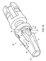
- FIG. 10 is an enlarged perspective view of an inner hub 50 according to a third example of the first embodiment.
- a recessed portion 51a at which an outer circumferential surface 51 of the inner hub 50 is recessed inward is formed in the outer circumferential surface 51.
- the example of FIG. 10 is different from the examples of FIGS. 7 and 9 in that the recessed portion 51a of the inner hub 50 includes a portion B extending in an axial direction of the inner hub 50.
- a portion of the recessed portion 51a is divided by a protrusion 52 which protrudes from a bottom surface of the recessed portion 51a.
- a portion A of the recessed portion 51a separated by the protrusion 52 is connected to the through-hole 22 in the circumferential direction.
- a liquid flows toward the tip 53 of the inner hub 50 as indicated by arrows "f" and "g.”
- flows (arrows "n” and "p") moving in the circumferential direction of the inner hub 50 occur.
- a top surface of the protrusion 52 is not in complete contact with the inner circumferential surface of the outer hub 5 ( FIG. 5 ), i.e., a gap is formed therebetween. Therefore, a part (the arrow "n") of the flow in the circumferential direction moves over the protrusion 52 and then moves further in the circumferential direction.
- the configuration of FIG. 10 is also advantageous for promoting the removal of air bubbles in the axial direction of the inner hub 50.
- FIG. 11 is an enlarged perspective view of an inner hub 60 according to a fourth example of the first embodiment.
- a recessed portion 61a at which an outer circumferential surface 61 of the inner hub 60 is recessed inward is formed in the outer circumferential surface 61.
- the example of FIG. 11 is different from the examples of FIGS. 7 and 9 in that the recessed portion 61a of the inner hub 60 includes a portion B extending in an axial direction of the inner hub 60.
- An opening of the through-hole 22 is surrounded by a protrusion 62, except for a portion in which the recessed portion 61a is formed.
- a portion A of the recessed portion 61a is connected to the through-hole 22 in the circumferential direction.
- a liquid flows toward the tip 63 of the inner hub 60 as indicated by arrows "f" and "g.”
- flows (arrows "n” and "p") moving in the circumferential direction of the inner hub 50 occur.
- the outer circumferential surface 61 of the inner hub 60 in which the recessed portion 61a is not formed is not in complete contact with the inner circumferential surface of the outer hub 5 ( FIG. 5 ), i.e., a gap is formed therebetween. Therefore, a part (the arrow "n") of the flow in the circumferential direction moves over the outer surface 61 and then moves further in the circumferential direction.
- FIG. 11 Similar to the configuration of FIG. 10 , the flows (the arrows "n” and “p") moving along the recessed portion 61a in the circumferential direction of the inner hub 60 are promoted, and a flow (an arrow "r") moving in the axial direction of the inner hub 60 is also promoted. Therefore, the configuration of FIG. 11 is also advantageous for promoting the removal of air bubbles in the axial direction of the inner hub 60.
- the shape of the inner hub is not limited to the above examples.
- the inner hub may have any shape as long as the opening of the through-hole and the recessed portion are connected together in the circumferential direction, and the recessed portion can guide a liquid flowing out from the opening of the through-hole in the circumferential direction of the inner hub.
- FIG. 12 is a perspective view showing an external appearance of an indwelling needle device 1B according to a second embodiment of the present invention.
- FIG. 13 is a cross-sectional view of the indwelling needle device 1B of FIG. 12 which is taken along a longitudinal direction thereof.
- FIG. 14 is an enlarged view of a tip portion of the indwelling needle device 1B of FIG. 13 .
- FIG. 15 is a cross-sectional view showing a state in which an inner needle 8, which was in the state of FIG. 13 , has been pulled into a shield cylinder 4.
- the indwelling needle device 1B includes a cylindrical body 2 in which an outer hub 5 is attached to a tip of the shield cylinder 4.
- the body 2 includes a needle portion 3 ( FIG. 13 ) at a tip portion thereof.
- a cap 6 is attached to the needle portion 3.
- the shield cylinder 4 and the outer hub 5 are made of, for example, polycarbonate, polypropylene, or the like.
- the needle portion 3 has a double structure in which the hard inner needle 8 made of a metal is inserted into a hollow portion of a tube-like soft outer needle 7.
- the outer needle 7 is fixed to the outer hub 5, and the inner needle 8 is fixed to an inner hub 9.
- the inner hub 9 is made of, for example, polycarbonate, polypropylene, or the like.
- the outer needle 7 is made of, for example, polyurethane elastomer, fluoroplastic such as polytetrafluoroethylene, or the like.
- the inner needle 8 does not project into a through-hole 22.
- the inner needle 8 may be fixed to the inner hub 9 so as to project into the through-hole 22.
- the inner hub 9 is housed in the body 2, and can be moved in the shield cylinder 4 in an axial direction of the shield cylinder 4.
- a sealing O-ring 15 is attached to the inner hub 9.
- a tube 10 is connected to a pipe-like portion 20 at a rear end of the inner hub 9 (see FIG. 16 ).
- the inner hub 9 is moved in the shield cylinder 4 in the direction indicated by the arrow "a.”
- the inner needle 8 integrated with the inner hub 9 is pulled into the shield cylinder 4 as shown in FIG. 15 .
- a ring portion 16 is attached to the shield cylinder 4, surrounding an outer circumference of the shield cylinder 4.
- a pair of wing portions 17 are integrated with the ring portion 16.
- a hub movement limiting member 11 is attached removably to the shield cylinder 4.
- the hub movement limiting member 11 includes a pair of cantilever portions 12. In FIG. 12 , although only one of the pair of cantilever portions 12 is shown, the pair of cantilever portions 12 are provided so as to sandwich the shield cylinder 4.
- a stopper 13 is integrated with the hub movement limiting member 11.
- the stopper 13 is inserted in the shield cylinder 4, and a tip 13a of the stopper 13 abuts a rear end surface 9a of the inner hub 9.
- the soft outer needle 7 is also inserted.
- the inner needle 8 and the outer needle 7 are inserted, if the cantilever portions 12 are released and the tube 10 is pulled in the direction indicated by the arrow "a," the inner needle 8 integrated with the inner hub 9 is pulled into the shield cylinder 4 as shown in FIG. 15 .
- the soft outer needle 7 is left at the insertion site. Therefore, even when the patient moves, pain at the insertion site can be relieved and damage to a blood vessel can be avoided.
- a liquid such as a drug solution etc. to be administered to a patient is supplied from the tube 10 to the inner hub 9.
- the inner hub 9 includes a flow path 21 extending along the axial direction of the inner hub 9, and the through-hole 22 penetrating the inner hub 9 in a radial direction thereof.
- the flow path 21 and the through-hole 22 are connected together.
- the liquid supplied to the inner hub 9 passes through the flow path 21 and the through-hole 22 to flow out of the inner hub 9.
- the liquid flowing out of the inner hub 9 passes through the body 2 to reach the hollow portion of the outer needle 7 before being administered to the patient's body.
- the indwelling needle device 1B when a drug solution etc. is administered, if air is present in the indwelling needle device 1B, the air enters a blood vessel along with the drug solution etc. Therefore, prior to insertion, the indwelling needle device 1B is filled with a liquid, such as a physiological saline, a nutrient solution, etc. This operation is called priming.
- a liquid such as a physiological saline, a nutrient solution, etc. This operation is called priming.
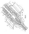
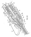
- FIG. 16 is an enlarged cross-sectional view of the vicinity of the inner hub 9 in FIG. 13 .
- FIG. 16 shows a cross-section of the inner hub 9 which is taken along a penetration direction of the through-hole 22.
- FIG. 17 is an enlarged cross-sectional view of the vicinity of the inner hub 9 which is taken along a direction perpendicular to the cross-section direction of FIG. 16 .
- FIG. 17 shows a cross-section of the inner hub 9 taken along the radial direction of the through-hole 22.
- FIG. 18 is an enlarged perspective view of the inner hub 9.
- the priming operation is performed while the inner needle 8 projects from the outer needle 7 as shown in FIG. 13 .
- a liquid such as physiological saline etc. is supplied from the tube 10 toward the inner hub 9 (in a direction indicated by an arrow "b").
- the liquid supplied to the inner hub 9 passes through the flow path 21 to flow into the through-hole 22.
- a portion of the liquid flowing into the through-hole 22 flows toward the outer circumferential surface of the inner hub 9, i.e., openings at both ends of the through-hole 22 (in directions indicated by arrows "c").
- Another portion of the liquid flowing into the through-hole 22 flows toward the inside of the inner needle 8 (in a direction indicated by an arrow "d").
- FIG. 18 is an enlarged perspective view of the inner hub 9.
- a recessed portion 23a in which the outer circumferential surface 23 of the inner hub 9 is recessed inward is formed in the outer circumferential surface 23.
- the outer circumferential surface 23 is uneven.
- a protrusion 25 which protrudes from the recessed portion 23a is formed on a side of the through-hole 22 closer to the tip 26 of the inner hub 9.
- FIG. 18 shows a portion of the outer circumferential surface 23 of the inner hub 9. An uneven portion similar to that of FIG. 18 is formed on a side (the back side of the drawing sheet) on which the other opening of the through-hole 22 is provided.
- the recessed portion 23a is formed by recessing the outer circumferential surface 23 inward. Therefore, as shown in FIG. 16 , a space 30 is formed between the recessed portion 23a and the inner circumferential surface of the outer hub 5.
- the space 30 of FIG. 16 corresponds to a portion between the protrusion 25 and the tip 26 of the inner hub 9, of the recessed portion 23a of the inner hub 9 of FIG. 18 .
- the protrusion 25 protruding from the recessed portion 23a in FIG. 18 is also shown in the cross-sectional view of FIG. 16 .
- a top surface of the protrusion 25 is close to the inner circumferential surface of the outer hub 5, but is not in complete contact therewith. Therefore, a gap 31b is formed between the top surface of the protrusion 25 and the inner circumferential surface of the outer hub 5.
- FIG. 18 When the protrusion 25 is viewed from above, a wall surface 25a of the protrusion 25 faces the opening of the through-hole 22. In other words, the wall surface 25a forms a portion of the inner circumferential surface of the through-hole 22. Therefore, when the liquid flows out of the through-hole 22 toward the tip 26 of the inner hub 9, the liquid flow is limited by the wall surface 25a of the protrusion 25, so that the liquid is divided into streams (the arrows "s” and "t") moving on both sides of the protrusion 25.
- the gap 31b is formed between the top surface of the protrusion 25 and the inner circumferential surface of the outer hub 5. Therefore, a flow (an arrow "g") occurs which enters the gap 31b and moves over the protrusion 25.
- the liquid flowing out of the through-hole 22 generally moves toward the tip 26 of the inner hub 9 in the axial direction of the inner hub 9.
- the protrusion 25 limits the flow of the liquid, and therefore, the flow of the liquid moving along the circumferential direction of the inner hub 9 also is promoted.
- the liquid that has reached the tip 26 of the inner hub 9 further moves toward the inside of the outer needle 7.
- the vicinity of the tip 26 of the inner hub 9 is not in complete contact with the inner circumferential surface of the outer hub 5, and therefore, a gap 33 is formed therebetween.
- a gap 34 is also formed between the hole of the outer hub 5 and the inner needle 8.
- a gap 35 is also formed between the inner circumferential surface of the outer needle 7 and the outer circumferential surface of the inner needle 8.
- the liquid flowing toward the tip 26 of the inner hub 9 passes through the gap 33, the gap 34, and the gap 35 and then flows out from the tip of the outer needle 7 (an arrow "h").
- the liquid moving in the direction indicated by the arrow “d” of FIG. 16 passes through the hollow portion of the inner needle 8 and then flows out from the tip of the inner needle 8 as indicated by an arrow "i” of FIG. 14 .
- the space and the gaps located between the through-hole 22 and the tips of the inner needle 8 and the outer needle 7 are filled with the liquid, i.e., air is removed from the space and the gaps.
- FIG. 19 is a perspective view of an inner hub 200 according to a comparative example.
- a through-hole 202 is formed in an even outer circumferential surface 201 of the inner hub 200, penetrating in a radial direction therethrough.
- neither the recessed portion 23a nor the protrusion 25 is formed in the outer circumferential surface 201 of the inner hub 200.
- a liquid from the through-hole 202 flows toward a tip 203 of the inner hub 200. Therefore, the liquid moving along a line connecting the through-hole 202 and the tip 203 forms a strong flow (an arrow "j"), and air is discharged easily along with this flow.
- a flow (an arrow "m") in a circumferential direction of the inner hub 200 is weak. Therefore, it gradually becomes more difficult for the liquid to reach a portion which is located farther away from the opening of the through-hole 202 in the circumferential direction of the inner hub 200. Therefore, air bubbles are more likely to remain at a portion farther away from the opening of the through-hole 202 in the circumferential direction of the inner hub 200.
- the formation of the protrusion 25 allows the liquid flowing out from the opening of the through-hole 22 to divide into streams moving on both sides in the circumferential direction of the protrusion 25, whereby the flow moving in the circumferential direction of the inner hub 9 can be promoted. Therefore, the removal of air bubbles is promoted even in a portion distant from the opening of the through-hole 22 in the circumferential direction of the inner hub 9.
- the opening of the through-hole 22 is interposed between the recessed portions 23a in the circumferential direction of the inner hub 9.
- the recessed portion 23a plays the role of a groove that guides the flow of the liquid in the circumferential direction of the inner hub 9, whereby the flow of the liquid moving in the circumferential direction of the inner hub 9 is promoted.
- air reliably can be replaced with the liquid by loading the liquid using the priming operation, whereby air bubbles can be prevented from remaining on the outer circumferential surface of the inner hub 9.
- the shape of the protrusion 25 is not limited to that shown in FIG. 18 .
- the protrusion 25 may have any shape as long as the liquid flowing out from the opening of the through-hole 22 and then moving toward the tip 26 of the inner hub 9 can be guided in the circumferential direction of the inner hub 9.
- side surfaces on both sides in the circumferential direction of the protrusion 25 are arranged to form a substantially V-shape, and therefore, the width in the circumferential direction of the protrusion 25 becomes gradually wider toward the through-hole 22.
- the wall surface 25a of the protrusion 25 can guide the liquid in the circumferential direction of the inner hub 9 immediately after the liquid flows out from the opening of the through-hole 22.
- the protrusion 25 has a sharp tapered tip portion (a portion C) closer to the tip 26, whereby air bubbles can be prevented from remaining at the tip portion C of the protrusion 25.
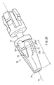
- FIG. 20 is a perspective view of an inner hub 40 according to a second example of the second embodiment.
- the inner hub 40 of FIG. 20 is different from the inner hub 9 of FIG. 18 in the position of the protrusion 25.
- a gap is not formed between the protrusion 25 and the opening of the through-hole 22.
- a gap having a dimension d is formed between the protrusion 25 and the opening of the through-hole 22.
- the dimension d is a dimension of a gap between the protrusion 25 and the opening of the through-hole 22 on a center axis 18 of the inner hub 9 when the inner hub 9 is viewed from above.
- the dimension d is preferably smaller than or equal to one half of a shortest distance L2 between the opening of the through-hole 22 and the tip 26 of the inner hub 9.
- the needle device according to the present invention can prevent air bubbles from remaining on the outer circumferential surface of the inner hub, and therefore, is useful as, for example, a medical needle device used for infusion and blood transfusion.
Landscapes
- Health & Medical Sciences (AREA)
- Life Sciences & Earth Sciences (AREA)
- Animal Behavior & Ethology (AREA)
- General Health & Medical Sciences (AREA)
- Biomedical Technology (AREA)
- Heart & Thoracic Surgery (AREA)
- Hematology (AREA)
- Engineering & Computer Science (AREA)
- Veterinary Medicine (AREA)
- Anesthesiology (AREA)
- Public Health (AREA)
- Vascular Medicine (AREA)
- Emergency Medicine (AREA)
- Infusion, Injection, And Reservoir Apparatuses (AREA)
- Biophysics (AREA)
- Pulmonology (AREA)
Abstract
Description
- The present invention relates to a needle device in which an inner hub with a needle integrated therewith is provided in a cylindrical body.
- Among known medical needle devices are, for example, indwelling needle devices, which are used for infusion and blood transfusion. A known indwelling needle device is one in which a needle portion projecting from a tip of a cylindrical body has a double structure including a soft outer needle and a hard inner needle (see
Patent Documents 1 and 2). - In such an indwelling needle device, when the hard inner needle which has been caused to project from the soft outer needle is inserted into a patient's arm etc., the soft outer needle is also inserted along with the hard inner needle. Thereafter, the hard inner needle is pulled into the cylindrical body, whereby only the soft outer needle is left at the insertion site. As a result, even when the patient moves, pain at the insertion site can be relieved and damage to a blood vessel can be prevented.
- The hard inner needle is integrated with the inner hub to which a tube is connected. By pulling the tube, the inner hub is moved, so that the hard inner needle integrated with the inner hub is pulled into the cylindrical body.
- In the above indwelling needle device, a drug solution etc. is supplied through the tube to the inner hub connected to the tube and then passed through the soft outer needle before being administered into a patient. When the drug solution etc. is administered, if air is present in the indwelling needle device, the air enters a blood vessel along with the drug solution etc.
- Therefore, prior to insertion, the indwelling needle device is filled with a liquid, such as physiological saline, a nutrient solution, etc. This operation is called priming.
-
- Patent Document 1:
JP 2006-297062A - Patent Document 2:
WO/2007/083770 - However, in the above conventional indwelling needle device, even if the priming operation is performed, it may be difficult to remove air bubbles from the indwelling needle device. This is because the liquid injected into the indwelling needle device is discharged through the inner hub. Specifically, the injected liquid temporarily flows into the inner hub, flows out of the inner hub through a hole formed in the inner hub, and passes through a gap between an outer circumferential surface of the inner hub and the cylindrical body, before reaching the outer needle. During this process, the liquid may not reach or spread sufficiently over the outer circumferential surface of the inner hub, and therefore, air bubbles may continue to remain on the outer circumferential surface of the inner hub.
- The present invention has been made to solve the above conventional problem. It is an object of the present invention to provide a needle device that can prevent air bubbles from remaining on the outer circumferential surface of the inner hub.
- A first needle device according to the present invention includes an inner hub with a needle attached to a tip thereof, and a cylindrical body housing the inner hub. The inner hub includes a through-hole penetrating the inner hub in a radial direction of the inner hub, and a recessed portion formed in an outer circumferential surface of the inner hub. An opening of the through-hole and the recessed portion are connected together in a circumferential direction of the inner hub.
- A second needle device according to the present invention includes an inner hub with a needle attached to a tip thereof, and a cylindrical body housing the inner hub. The inner hub includes a through-hole penetrating the inner hub in a radial direction of the inner hub, and a protrusion formed between an opening of the through-hole and the tip of the inner hub and protruding from an outer circumferential surface of the inner hub.
- According to the present invention, air bubbles can be prevented from remaining on the outer circumferential surface of the inner hub.
-
- [
FIG. 1] FIG. 1 is a perspective view of the external appearance of an indwellingneedle device 1A according to a first embodiment of the present invention. - [
FIG. 2] FIG. 2 is a cross-sectional view of the indwellingneedle device 1A ofFIG. 1 which is taken along a longitudinal direction thereof. - [
FIG. 3] FIG. 3 is an enlarged view of a tip portion of the indwellingneedle device 1A ofFIG. 2 . - [
FIG. 4] FIG. 4 is a cross-sectional view showing a state in which aninner needle 8, which was in the state ofFIG. 2 , has been pulled into ashield cylinder 4. - [
FIG. 5] FIG. 5 is an enlarged cross-sectional view of the vicinity of aninner hub 9 according to the first embodiment of the present invention, showing a cross-section of theinner hub 9 which is taken along a penetration direction of a through-hole 22. - [
FIG. 6] FIG. 6 is an enlarged cross-sectional view of the vicinity of theinner hub 9 according to the first embodiment of the present invention, showing a cross-section of theinner hub 9 which is taken along a radial direction of the through-hole 22. - [
FIG. 7] FIG. 7 is an enlarged perspective view of theinner hub 9 according to the first embodiment of the present invention. - [
FIG. 8] FIG. 8 is an enlarged perspective view of aninner hub 100 according to a comparative example. - [
FIG. 9] FIG. 9 is an enlarged perspective view of aninner hub 40 according to a second example of the first embodiment of the present invention. - [
FIG. 10] FIG. 10 is an enlarged perspective view of aninner hub 50 according to a third example of the first embodiment of the present invention. - [
FIG. 11] FIG. 11 is an enlarged perspective view of aninner hub 60 according to a fourth example of the first embodiment of the present invention. - [
FIG. 12] FIG. 12 is a perspective view showing the external appearance of an indwellingneedle device 1B according to a second embodiment of the present invention. - [
FIG. 13] FIG. 13 is a cross-sectional view of the indwellingneedle device 1B ofFIG. 12 which is taken along a longitudinal direction thereof. - [
FIG. 14] FIG. 14 is an enlarged view of a tip portion of the indwellingneedle device 1B ofFIG. 13 . - [
FIG. 15] FIG. 15 is a cross-sectional view showing a state in which aninner needle 8, which was in the state ofFIG. 13 , has been pulled into ashield cylinder 4. - [
FIG. 16] FIG. 16 is an enlarged cross-sectional view of the vicinity of aninner hub 9 according to the second embodiment of the present invention, showing a cross-section of theinner hub 9 which is taken along a penetration direction of a through-hole 22. - [
FIG. 17] FIG. 17 is an enlarged cross-sectional view of the vicinity of theinner hub 9 according to the second embodiment of the present invention, showing a cross-section of theinner hub 9 which is taken along a radial direction of the through-hole 22. - [
FIG. 18] FIG. 18 is an enlarged perspective view of theinner hub 9 according to the second embodiment of the present invention. - [
FIG. 19] FIG. 19 is an enlarged perspective view of aninner hub 200 according to a comparative example. - [
FIG. 20] FIG. 20 is an enlarged perspective view of aninner hub 40 according to a second example of the embodiment of the present invention. - According to the first needle device of the present invention, the recessed portion connected to the opening of the through-hole in the circumferential direction of the inner hub is formed in the outer circumferential surface of the inner hub. Therefore, the flow of a liquid flowing out from the opening of the through-hole is limited so that the liquid flows along the recessed portion, whereby the flow of the liquid moving in the circumferential direction of the inner hub can be promoted. As a result, the removal of air bubbles in the circumferential direction of the inner hub is promoted. Therefore, according to the present invention, when a liquid is injected into the needle device in the priming operation, air can be replaced reliably with the liquid, whereby air bubbles can be prevented from remaining on the outer circumferential surface of the inner hub.
- In the first needle device of the present invention, the recessed portion is preferably arranged to guide a liquid flowing out from the opening of the through-hole in the circumferential direction of the inner hub.
- The opening of the through-hole is preferably interposed between the recessed portions in the circumferential direction of the inner hub. This configuration is advantageous for promoting the removal of air bubbles in the circumferential direction of the inner hub.
- The recessed portions are preferably separated from each other by a separator surface serving as a boundary, and preferably include a portion whose depth becomes gradually shallower in a direction from the opening of the through-hole to the separator surface. This configuration allows air bubbles to move more easily up onto the top of the separator surface along with the liquid and then flow toward the tip of the inner hub. Thus, this configuration is advantageous for promoting the removal of air bubbles.
- The recessed portion preferably includes a portion extending in an axial direction of the inner hub. This configuration is advantageous for promoting the removal of air bubbles in the axial direction of the inner hub.
- The width of the recessed portion is preferably smaller than or equal to one half of the length of the opening of the through-hole in an axial direction of the inner hub. With this configuration, the flow of the liquid is concentrated into a portion in which air bubbles are likely to remain. Thus, this configuration is advantageous for removing air bubbles.
- According to the second needle device of the present invention, the protrusion is provided on the inner hub. Therefore, a liquid flowing out from the opening of the through-hole formed in the inner hub is divided into streams moving on both sides of the protrusion, whereby the flow of the liquid moving in the circumferential direction of the inner hub can be promoted. As a result, the removal of air bubbles in the circumferential direction of the inner hub is promoted. Therefore, according to the present invention, when a liquid is injected into the needle device in the priming operation, air can be reliably replaced with the liquid, whereby air bubbles can be prevented from remaining on the outer circumferential surface of the inner hub.
- In the second needle device of the present invention, the inner hub preferably includes a recessed portion at which the outer circumferential surface of the inner hub is recessed inward, and the protrusion preferably protrudes from the recessed portion. With this configuration, the protrusion can be formed while an outer diameter dimension of the inner hub is maintained.
- The protrusion is preferably arranged to guide a liquid flowing out from the opening of the through-hole in a circumferential direction of the inner hub.
- When the protrusion is viewed from above, a wall surface of the protrusion preferably faces the opening of the through-hole. With this configuration, the flow of the liquid flowing out of the through-hole is limited by the wall surface of the protrusion so that the liquid is divided into streams moving on both sides of the protrusion, whereby the flow of the liquid moving in the circumferential direction of the inner hub is promoted.
- The opening of the through-hole preferably is interposed between the recessed portions in a circumferential direction of the inner hub. With this configuration, the recessed portion plays the role of a groove that guides the flow of the liquid in the circumferential direction of the inner hub. Thus, this configuration is advantageous for promoting the flow of the liquid moving in the circumferential direction of the inner hub.
- When the inner hub is viewed from above, on a center axis of the inner hub, a dimension of a gap between the protrusion and the opening of the through-hole is preferably smaller than or equal to one half of a shortest distance between the opening of the through-hole and the tip of the inner hub. With this configuration, the liquid more easily moves and spreads from the through-hole of the inner hub in the circumferential direction of the inner hub. Thus, this configuration is more advantageous for removing air bubbles.
- When the inner hub is viewed from above, side surfaces on both sides of the protrusion preferably are arranged to form a substantially V shape, and the width of the protrusion preferably becomes gradually wider toward the through-hole. With this configuration, the protrusion has a sharp tapered tip portion, whereby air bubbles can be prevented from remaining at the tip portion of the protrusion.
- The present invention will be described in detail hereinafter with reference to preferred embodiments. Note that the present invention is not intended to be limited to the embodiments described below. The drawings referenced herein schematically show only the main components necessary for description of the present invention, of the components of the embodiments of the present invention, for the sake of convenience. Therefore, the present invention may include suitable components that are not shown in the drawings.
- The present invention relates to a needle device. In the embodiments described below, the needle device of the present invention will be described using an example medical indwelling needle device whose needle portion has a double structure including an outer needle and an inner needle. Such an indwelling needle device is used for infusion and blood transfusion. Infusion and blood transfusion are performed while only the soft outer needle is left at an insertion site.
-
FIG. 1 is a perspective view of an external appearance of anindwelling needle device 1A according to a first embodiment of the present invention.FIG. 2 is a cross-sectional view of theindwelling needle device 1A ofFIG. 1 which is taken along a longitudinal direction thereof.FIG. 3 is an enlarged view of a tip portion of theindwelling needle device 1A ofFIG. 2 .FIG. 4 is a cross-sectional view showing a state in which aninner needle 8, which was in the state ofFIG. 2 , has been pulled into ashield cylinder 4. Firstly, a basic configuration of theindwelling needle device 1A will be described with reference toFIGS. 1-4 . - In
FIGS. 1 and2 , the indwellingneedle device 1A includes acylindrical body 2 in which anouter hub 5 is attached to a tip of theshield cylinder 4. Thebody 2 includes a needle portion 3 (FIG. 2 ) at a tip portion thereof. InFIG. 1 , acap 6 is attached to theneedle portion 3. Theshield cylinder 4 and theouter hub 5 are made of, for example, polycarbonate, polypropylene, or the like. - As shown in
FIG. 3 , theneedle portion 3 has a double structure in which the hardinner needle 8 made of a metal is inserted in a hollow portion of a tube-like softouter needle 7. Theouter needle 7 is fixed to theouter hub 5, and theinner needle 8 is fixed to aninner hub 9. Theinner hub 9 is made of, for example, polycarbonate, polypropylene, or the like. Theouter needle 7 is made of, for example, polyurethane elastomer, fluoroplastic such as polytetrafluoroethylene, or the like. - In
FIG. 3 , theinner needle 8 is inserted in ahole 27 of theinner hub 9. By applying an adhesive to anend portion 27a of thehole 27, theinner needle 8 can be fixed to theinner hub 9. Theinner needle 8 projects into a through-hole 22. If the amount by which theinner needle 8 protrudes is set to be sufficiently large, even when the projecting amount of theinner needle 8 varies during manufacture, theinner needle 8 is allowed to project into the through-hole 22. For example, as shown inFIGS. 6 and7 described below, the length of the through-hole 22 in an axial direction of theinner hub 9 is set to be long enough to ensure a sufficient projecting amount of theinner needle 8 into the through-hole 22. As a result, a sufficient distance is ensured between theend portion 27a of thehole 27 and anend portion 8a of theinner needle 8, and therefore, the adhesive is prevented from entering the hollow portion of theinner needle 8 and thereby clogging theinner needle 8. Note that, as in a second embodiment described below, theinner needle 8 may be fixed to theinner hub 9 without causing theinner needle 8 to project into the through-hole 22. - As shown in
FIG. 2 , theinner hub 9 is housed in thebody 2 and can be moved in theshield cylinder 4 in an axial direction of theshield cylinder 4. A sealing O-ring 15 is attached to theinner hub 9. Atube 10 is connected to a pipe-like portion 20 at a rear end of the inner hub 9 (seeFIG. 5 ). By pulling thetube 10 in a direction indicated by an arrow "a," theinner hub 9 is moved in theshield cylinder 4 in the direction indicated by the arrow "a." As a result, theinner needle 8 integrated with theinner hub 9 is pulled into theshield cylinder 4 as shown inFIG. 4 . - In
FIG. 1 , aring portion 16 is attached to theshield cylinder 4, surrounding an outer circumference of theshield cylinder 4. A pair ofwing portions 17 are integrated with thering portion 16. Moreover, a hubmovement limiting member 11 is attached removably to theshield cylinder 4. The hubmovement limiting member 11 includes a pair ofcantilever portions 12. InFIG. 1 , although only one of the pair ofcantilever portions 12 is shown, the pair ofcantilever portions 12 are provided so as to sandwich theshield cylinder 4. - In the state of
FIG. 1 , when the pair ofwing portions 17 are lifted up and grasped,tip portions 12a of the pair ofcantilever portions 12 are grasped while being pressed against thering portion 16 via the pair ofwing portions 17. While the pair ofcantilever portions 12 are grasped in this manner, the hubmovement limiting member 11 is fixed to theshield cylinder 4. - Moreover, as shown in
FIG. 2 , astopper 13 is integrated with the hubmovement limiting member 11. In the state ofFIG. 2 , thestopper 13 is inserted in theshield cylinder 4, and atip 13a of thestopper 13 abuts arear end surface 9a of theinner hub 9. - Therefore, when the
cantilever portions 12 of the hubmovement limiting member 11 are grasped, movement of theinner hub 9, and also theinner needle 8 integrated with theinner hub 9, is limited. Therefore, in this state, theinner needle 8 can be inserted into a patient without being pushed back toward theshield cylinder 4. - When the
inner needle 8 is inserted, the softouter needle 7 is also inserted. After theinner needle 8 and theouter needle 7 are inserted, if thecantilever portions 12 are released and thetube 10 is pulled in the direction indicated by the arrow "a," theinner needle 8 integrated with theinner hub 9 is pulled into theshield cylinder 4 as shown inFIG. 4 . As a result, only the softouter needle 7 is left at the insertion site. Therefore, even when the patient moves, pain at the insertion site can be relieved, and damage to a blood vessel can be avoided. - In the state of
FIG. 4 , a liquid such as a drug solution etc. to be administered to a patient is supplied from thetube 10 to theinner hub 9. Theinner hub 9 includes aflow path 21 extending along the axial direction of theinner hub 9, and the through-hole 22 penetrating theinner hub 9 in a radial direction thereof. Theflow path 21 and the through-hole 22 are connected together. The liquid supplied to theinner hub 9 passes through theflow path 21 and the through-hole 22 before flowing out of theinner hub 9. The liquid flowing out of theinner hub 9 passes through thebody 2 to reach the hollow portion of theouter needle 7 before being administered to the patient's body. - Here, when a drug solution etc. is administered, if air is present in the
indwelling needle device 1A, the air enters a blood vessel along with the drug solution etc. Therefore, prior to insertion, the indwellingneedle device 1A is filled with a liquid, such as physiological saline, a nutrient solution, etc. This operation is called priming. - The flow of the liquid during the priming operation will be described with reference to
FIGS. 5-7 .FIG. 5 is an enlarged cross-sectional view of the vicinity of theinner hub 9 inFIG. 2 .FIG. 5 shows a cross-section of theinner hub 9 which is taken along a penetration direction of the through-hole 22.FIG. 6 is an enlarged cross-sectional view of the vicinity of theinner hub 9 which is taken along a direction perpendicular to the cross-section direction ofFIG. 5 . In other words,FIG. 6 shows a cross-section of theinner hub 9 taken along the radial direction of the through-hole 22.FIG. 7 is an enlarged perspective view of theinner hub 9. - The priming operation is performed while the
inner needle 8 projects from theouter needle 7 as shown inFIG. 2 . InFIG. 5 , during the priming operation, a liquid such as physiological saline etc. is supplied from thetube 10 toward the inner hub 9 (in a direction indicated by an arrow "b"). The liquid supplied to theinner hub 9 passes through theflow path 21 to flow into the through-hole 22. A portion of the liquid flowing into the through-hole 22 flows toward the outer circumferential surface of theinner hub 9, i.e., openings at both ends of the through-hole 22 (in directions indicated by arrows "c"). Another portion of the liquid flowing into the through-hole 22 flows toward the inside of the inner needle 8 (in a direction indicated by an arrow "d"). - The liquid flowing in the directions indicated by the arrows "c" passes through a gap between the outer circumferential surface of the
inner hub 9 and an inner circumferential surface of theouter hub 5 to flow toward atip 26 of theinner hub 9. Before describing the flow of the liquid flowing out from the openings at both ends of the through-hole 22, a configuration of theinner hub 9 and a relationship between theinner hub 9 and theouter hub 5 will be described. -
FIG. 7 is an enlarged perspective view of theinner hub 9. Recessedportions 23a in which the outercircumferential surface 23 of theinner hub 9 is recessed inward are formed in the outercircumferential surface 23. The recessedportions 23a are connected to the openings of the through-hole 22. In the example ofFIG. 7 , the through-hole 22 is interposed between the recessedportions 23a in a circumferential direction of theinner hub 9. The recessedportions 23a are separated byseparator surfaces 23b serving as boundaries. - Note that
FIG. 7 shows a portion of the outer circumferential surface of theinner hub 9. Similar toFIG. 7 , recessedportions 23a are formed on a side (on the back side of the drawing sheet) on which the other opening of the through-hole 22 is provided, with the through-hole 22 being interposed between the recessedportions 23a in the circumferential direction of theinner hub 9. The recessedportions 23a connected to one opening of the through-hole 22 and the recessedportions 23a connected to the other opening of the through-hole 22 are separated from each other by a pair of the separator surfaces 23b. Therefore, the recessedportions 23 are not continuous in the circumferential direction. - The flow of a liquid flowing out of the through-
hole 22 will be described specifically hereinafter. Arrows "e," "f," and "g" ofFIG. 7 indicate directions of the flow of the liquid flowing out of the through-hole 22. As shown inFIG. 7 , both sides of the opening of the through-hole 22 in the circumferential direction of theinner hub 9 are connected to the pair of recessedportions 23a. At a portion in which the recessedportion 23a is formed, the flow of the liquid is guided by the recessedportion 23a. - Therefore, a part of the liquid flowing out of the through-
hole 22 is limited so that the part of the liquid flows along the recessedportions 23a. Therefore, flows (arrows "e") moving in the circumferential direction of theinner hub 9 occur on both sides of the through-hole 22. - As described above, the recessed
portions 23a are separated from each other by the separator surfaces 23b serving as boundaries. The depth of the recessedportion 23a becomes gradually shallower in a direction from the opening of the through-hole 22 to theseparator surface 23b. Theseparator surface 23b is closer to the inner circumferential surface of theouter hub 5 than the recessedportion 23a is, but is not in complete contact therewith (seeFIG. 6 ). Therefore, agap 30 is formed between theseparator surface 23b and the inner circumferential surface of theouter hub 5. Therefore, the liquid flow indicated by the arrow "e" ofFIG. 7 moves up onto theseparator surface 23b. After reaching theseparator surface 23b, the liquid flows in thegap 30 toward thetip 26 of theinner hub 9. -
FIGS. 5 and6 show the outercircumferential surface 23 of theinner hub 9 in a portion in which the recessedportion 23a is not formed. The outercircumferential surface 23 of theinner hub 9 shown inFIGS. 5 and6 is close to the inner circumferential surface of theouter hub 5, but is not in complete contact therewith. Therefore, agap 31 is formed between the outercircumferential surface 23 of theinner hub 9 and the inner circumferential surface of theouter hub 5. Therefore, the liquid indicated by the arrows "f" and "g" ofFIG. 7 flows in the gap 31 (FIGS. 5 and6 ) toward thetip 26 of theinner hub 9. - In other words, the liquid flowing out of the through-
hole 22 generally moves in the axial direction of theinner hub 9 toward thetip 26 of theinner hub 9. However, the recessedportion 23a limits the flow of the liquid, and therefore, the flow of the liquid moving along the circumferential direction of theinner hub 9 also is promoted. - In
FIG. 3 , the liquid which has reached thetip 26 of theinner hub 9 further moves toward the inside of theouter needle 7. The vicinity of thetip 26 of theinner hub 9 is not in complete contact with the inner circumferential surface of theouter hub 5, and therefore, agap 33 is formed therebetween. Agap 34 is also formed between the hole of theouter hub 5 and theinner needle 8. Agap 35 is also formed between the inner circumferential surface of theouter needle 7 and the outer circumferential surface of theinner needle 8. - Therefore, the liquid flowing in the
gap 31 toward thetip 26 of theinner hub 9 passes through thegap 33, thegap 34, and thegap 35 and then flows out from the tip of the outer needle 7 (an arrow "h"). On the other hand, the liquid moving in the direction indicated by the arrow "d" ofFIG. 5 passes through the hollow portion of theinner needle 8 and then flows out from the tip of theinner needle 8 as indicated by an arrow "i" ofFIG. 3 . - Therefore, by performing the above priming operation on the
indwelling needle device 1A, the space and the gaps located between the through-hole 22 and the tips of theinner needle 8 and theouter needle 7 are filled with the liquid, i.e., air is removed from the space and the gaps. - Next, the
inner hub 9 of the first embodiment will be described by comparing it with a comparative example.FIG. 8 is a perspective view of aninner hub 100 according to the comparative example. A through-hole 102 is formed in an even outercircumferential surface 101 of theinner hub 100, penetrating therethrough in a radial direction. Unlike theinner hub 9 ofFIG. 7 , the recessedportion 23a is not formed in the outercircumferential surface 101 of theinner hub 100. - In the
inner hub 100 ofFIG. 8 , a liquid from the through-hole 102 flows toward atip 103 of theinner hub 100. Therefore, the liquid moving toward thetip 103 of theinner hub 100 forms a strong flow (arrows "j" and "k"), and air is discharged easily along with this flow. - In contrast to this, a flow (an arrow "m") in a circumferential direction of the
inner hub 100 is weak. Therefore, it gradually becomes more difficult for the liquid to reach a portion which is located farther away from the opening of the through-hole 102 in the circumferential direction of theinner hub 100. Therefore, air bubbles are more likely to remain at a portion located farther away from the opening of the through-hole 102 in the circumferential direction of theinner hub 100. - In the first embodiment, as described above, as shown in
FIG. 7 , the formation of the recessedportion 23a allows the liquid flowing out from the opening of the through-hole 22 to divide into streams moving on both sides in the circumferential direction of the through-hole 22, whereby the flow moving in the circumferential direction of theinner hub 9 can be promoted. Therefore, the removal of air bubbles is promoted even in a portion distant from the opening of the through-hole 22 in the circumferential direction of theinner hub 9. - As described above, the depth of the recessed
portion 23a becomes gradually shallower in a direction from the opening of the through-hole 22 to theseparator surface 23b. Therefore, it is more likely that air bubbles move up onto theseparator surface 23b along with the flow of the liquid, and then flow toward thetip 26 of theinner hub 9. This is also advantageous for promoting the removal of air bubbles. - Note that the entirety or a portion of the recessed
portion 23a may become gradually shallower toward theseparator surface 23b. For example, the depth of the recessedportion 23a may be constant in a region extending from the opening of the through-hole 22 to some point in the circumferential direction, and may become gradually shallower toward theseparator surface 23b in a region extending from this point to theseparator surface 23. - Therefore, according to this embodiment, air reliably can be replaced with the liquid by loading the liquid using the priming operation, whereby air bubbles can be prevented from remaining on the outer circumferential surface of the
inner hub 9. - According to the inventors' experimental studies, the air bubbles remaining tend to occur selectively at a specific portion, rather than on the entire outer circumferential surface of the
inner hub 9. Therefore, in order to achieve removal of air bubbles, it is effective to avoid an excessively large recessedportion 23a so that the flow of the liquid is concentrated into a portion in which air bubbles are likely to remain. Specifically, as shown inFIG. 7 , a width W of the recessedportion 23a in the axial direction of theinner hub 9 is preferably smaller than or equal to one half of a length L of the opening of the through-hole 22. This holds true in the examples ofFIGS. 9-11 described below. - Other examples will be described hereinafter with reference to
FIGS. 9-11 . Components which are the same as or similar to those of the above example are indicated by the same reference characters and will not be described. WhileFIGS. 9-11 show a side on which one of the openings of the through-hole 22 is provided, a shape similar to that ofFIGS. 9-11 is provided on a side on which the other opening of the through-hole 22 is provided. -
FIG. 9 is an enlarged perspective view of aninner hub 40 according to a second example of the first embodiment. While the recessedportions 23a are separated from each other in the circumferential direction by the separator surfaces 23b serving as boundaries in theinner hub 9 ofFIG. 7 , a recessedportion 23a is formed over the entire circumference of theinner hub 40 ofFIG. 9 except for a portion in which the through-hole 22 is formed. - With this configuration, similar to the example of
FIG. 7 , a liquid flows toward thetip 26 of theinner hub 9 as indicated by arrows "f" and "g." Moreover, with this configuration, similar to the example ofFIG. 7 , a flow (an arrow "e") of the liquid moving along the recessedportion 23a in the circumferential direction of theinner hub 40 can be promoted, whereby the removal of air bubbles can be promoted. -
FIG. 10 is an enlarged perspective view of aninner hub 50 according to a third example of the first embodiment. A recessedportion 51a at which an outercircumferential surface 51 of theinner hub 50 is recessed inward is formed in the outercircumferential surface 51. The example ofFIG. 10 is different from the examples ofFIGS. 7 and9 in that the recessedportion 51a of theinner hub 50 includes a portion B extending in an axial direction of theinner hub 50. - A portion of the recessed
portion 51a is divided by aprotrusion 52 which protrudes from a bottom surface of the recessedportion 51a. A portion A of the recessedportion 51a separated by theprotrusion 52 is connected to the through-hole 22 in the circumferential direction. A portion (the portion B) of the recessedportion 51a which is closer to atip 53 of theinner hub 9 than the portion A is, is formed to extend in the axial direction of theinner hub 50. - In the example of
FIG. 10 , similar to the example ofFIG. 7 , a liquid flows toward thetip 53 of theinner hub 50 as indicated by arrows "f" and "g." At the portion A of the recessedportion 51a, flows (arrows "n" and "p") moving in the circumferential direction of theinner hub 50 occur. A top surface of theprotrusion 52 is not in complete contact with the inner circumferential surface of the outer hub 5 (FIG. 5 ), i.e., a gap is formed therebetween. Therefore, a part (the arrow "n") of the flow in the circumferential direction moves over theprotrusion 52 and then moves further in the circumferential direction. - Therefore, with the configuration of
FIG. 10 , the flows (the arrows "n" and "p") moving along the recessedportion 51a in the circumferential direction of theinner hub 50 are promoted, and a flow (an arrow "r") moving in the axial direction of theinner hub 50 also is promoted. Therefore, the configuration ofFIG. 10 is also advantageous for promoting the removal of air bubbles in the axial direction of theinner hub 50. -
FIG. 11 is an enlarged perspective view of aninner hub 60 according to a fourth example of the first embodiment. A recessedportion 61a at which an outercircumferential surface 61 of theinner hub 60 is recessed inward is formed in the outercircumferential surface 61. The example ofFIG. 11 is different from the examples ofFIGS. 7 and9 in that the recessedportion 61a of theinner hub 60 includes a portion B extending in an axial direction of theinner hub 60. - An opening of the through-
hole 22 is surrounded by aprotrusion 62, except for a portion in which the recessedportion 61a is formed. A portion A of the recessedportion 61a is connected to the through-hole 22 in the circumferential direction. A portion (a portion B) of the recessedportion 61a which is closer to atip 63 of theinner hub 60 than the portion A is, is formed to extend in the axial direction of theinner hub 60. - In the example of
FIG. 11 , similar to the example ofFIG. 7 , a liquid flows toward thetip 63 of theinner hub 60 as indicated by arrows "f" and "g." At the portion A of the recessedportion 61a, flows (arrows "n" and "p") moving in the circumferential direction of theinner hub 50 occur. The outercircumferential surface 61 of theinner hub 60 in which the recessedportion 61a is not formed is not in complete contact with the inner circumferential surface of the outer hub 5 (FIG. 5 ), i.e., a gap is formed therebetween. Therefore, a part (the arrow "n") of the flow in the circumferential direction moves over theouter surface 61 and then moves further in the circumferential direction. - Therefore, with the configuration of
FIG. 11 , similar to the configuration ofFIG. 10 , the flows (the arrows "n" and "p") moving along the recessedportion 61a in the circumferential direction of theinner hub 60 are promoted, and a flow (an arrow "r") moving in the axial direction of theinner hub 60 is also promoted. Therefore, the configuration ofFIG. 11 is also advantageous for promoting the removal of air bubbles in the axial direction of theinner hub 60. - Various example inner hubs have been described above. The shape of the inner hub is not limited to the above examples. The inner hub may have any shape as long as the opening of the through-hole and the recessed portion are connected together in the circumferential direction, and the recessed portion can guide a liquid flowing out from the opening of the through-hole in the circumferential direction of the inner hub.
-
FIG. 12 is a perspective view showing an external appearance of anindwelling needle device 1B according to a second embodiment of the present invention.FIG. 13 is a cross-sectional view of theindwelling needle device 1B ofFIG. 12 which is taken along a longitudinal direction thereof.FIG. 14 is an enlarged view of a tip portion of theindwelling needle device 1B ofFIG. 13 .FIG. 15 is a cross-sectional view showing a state in which aninner needle 8, which was in the state ofFIG. 13 , has been pulled into ashield cylinder 4. Firstly, a basic configuration of theindwelling needle device 1B will be described with reference toFIGS. 12-15 . - In
FIGS. 12 and13 , the indwellingneedle device 1B includes acylindrical body 2 in which anouter hub 5 is attached to a tip of theshield cylinder 4. Thebody 2 includes a needle portion 3 (FIG. 13 ) at a tip portion thereof. InFIG. 12 , acap 6 is attached to theneedle portion 3. Theshield cylinder 4 and theouter hub 5 are made of, for example, polycarbonate, polypropylene, or the like. - As shown in
FIG. 14 , theneedle portion 3 has a double structure in which the hardinner needle 8 made of a metal is inserted into a hollow portion of a tube-like softouter needle 7. Theouter needle 7 is fixed to theouter hub 5, and theinner needle 8 is fixed to aninner hub 9. Theinner hub 9 is made of, for example, polycarbonate, polypropylene, or the like. Theouter needle 7 is made of, for example, polyurethane elastomer, fluoroplastic such as polytetrafluoroethylene, or the like. - In the second embodiment, the
inner needle 8 does not project into a through-hole 22. Alternatively, similar to the first embodiment, theinner needle 8 may be fixed to theinner hub 9 so as to project into the through-hole 22. - As shown in
FIG. 13 , theinner hub 9 is housed in thebody 2, and can be moved in theshield cylinder 4 in an axial direction of theshield cylinder 4. A sealing O-ring 15 is attached to theinner hub 9. Atube 10 is connected to a pipe-like portion 20 at a rear end of the inner hub 9 (seeFIG. 16 ). By pulling thetube 10 in a direction indicated by an arrow "a," theinner hub 9 is moved in theshield cylinder 4 in the direction indicated by the arrow "a." As a result, theinner needle 8 integrated with theinner hub 9 is pulled into theshield cylinder 4 as shown inFIG. 15 . - In
FIG. 12 , aring portion 16 is attached to theshield cylinder 4, surrounding an outer circumference of theshield cylinder 4. A pair ofwing portions 17 are integrated with thering portion 16. Moreover, a hubmovement limiting member 11 is attached removably to theshield cylinder 4. The hubmovement limiting member 11 includes a pair ofcantilever portions 12. InFIG. 12 , although only one of the pair ofcantilever portions 12 is shown, the pair ofcantilever portions 12 are provided so as to sandwich theshield cylinder 4. - In the state of
FIG. 12 , when the pair ofwing portions 17 are lifted up and grasped,tip portions 12a of the pair ofcantilever portions 12 are grasped while being pressed against thering portion 16 via the pair ofwing portions 17. While the pair ofcantilever portions 12 are grasped in this manner, the hubmovement limiting member 11 is fixed to theshield cylinder 4. - Moreover, as shown in
FIG. 13 , astopper 13 is integrated with the hubmovement limiting member 11. In the state ofFIG. 13 , thestopper 13 is inserted in theshield cylinder 4, and atip 13a of thestopper 13 abuts arear end surface 9a of theinner hub 9. - Therefore, when the
cantilever portions 12 of the hubmovement limiting member 11 are grasped, movement of theinner hub 9, and also theinner needle 8 integrated with theinner hub 9, is limited. Therefore, in this state, theinner needle 8 can be inserted into a patient without being pushed back toward theshield cylinder 4. - When the
inner needle 8 is inserted, the softouter needle 7 is also inserted. After theinner needle 8 and theouter needle 7 are inserted, if thecantilever portions 12 are released and thetube 10 is pulled in the direction indicated by the arrow "a," theinner needle 8 integrated with theinner hub 9 is pulled into theshield cylinder 4 as shown inFIG. 15 . As a result, only the softouter needle 7 is left at the insertion site. Therefore, even when the patient moves, pain at the insertion site can be relieved and damage to a blood vessel can be avoided. - In the state of
FIG. 15 , a liquid such as a drug solution etc. to be administered to a patient is supplied from thetube 10 to theinner hub 9. Theinner hub 9 includes aflow path 21 extending along the axial direction of theinner hub 9, and the through-hole 22 penetrating theinner hub 9 in a radial direction thereof. Theflow path 21 and the through-hole 22 are connected together. The liquid supplied to theinner hub 9 passes through theflow path 21 and the through-hole 22 to flow out of theinner hub 9. The liquid flowing out of theinner hub 9 passes through thebody 2 to reach the hollow portion of theouter needle 7 before being administered to the patient's body. - Here, when a drug solution etc. is administered, if air is present in the
indwelling needle device 1B, the air enters a blood vessel along with the drug solution etc. Therefore, prior to insertion, the indwellingneedle device 1B is filled with a liquid, such as a physiological saline, a nutrient solution, etc. This operation is called priming. - The flow of the liquid during the priming operation will be described with reference to
FIGS. 16-18 .FIG. 16 is an enlarged cross-sectional view of the vicinity of theinner hub 9 inFIG. 13 .FIG. 16 shows a cross-section of theinner hub 9 which is taken along a penetration direction of the through-hole 22.FIG. 17 is an enlarged cross-sectional view of the vicinity of theinner hub 9 which is taken along a direction perpendicular to the cross-section direction ofFIG. 16 . In other words,FIG. 17 shows a cross-section of theinner hub 9 taken along the radial direction of the through-hole 22.FIG. 18 is an enlarged perspective view of theinner hub 9. - The priming operation is performed while the
inner needle 8 projects from theouter needle 7 as shown inFIG. 13 . InFIG. 16 , during the priming operation, a liquid such as physiological saline etc. is supplied from thetube 10 toward the inner hub 9 (in a direction indicated by an arrow "b"). The liquid supplied to theinner hub 9 passes through theflow path 21 to flow into the through-hole 22. A portion of the liquid flowing into the through-hole 22 flows toward the outer circumferential surface of theinner hub 9, i.e., openings at both ends of the through-hole 22 (in directions indicated by arrows "c"). Another portion of the liquid flowing into the through-hole 22 flows toward the inside of the inner needle 8 (in a direction indicated by an arrow "d"). - The liquid flowing in the directions indicated by the arrows "c" passes through a gap between the outer circumferential surface of the
inner hub 9 and an inner circumferential surface of theouter hub 5 to flow toward atip 26 of theinner hub 9. Before describing the flow of the liquid flowing out from the openings at both ends of the through-hole 22, a configuration of theinner hub 9 and a relationship between theinner hub 9 and theouter hub 5 will be described. -
FIG. 18 is an enlarged perspective view of theinner hub 9. A recessedportion 23a in which the outercircumferential surface 23 of theinner hub 9 is recessed inward is formed in the outercircumferential surface 23. The outercircumferential surface 23 is uneven. Aprotrusion 25 which protrudes from the recessedportion 23a is formed on a side of the through-hole 22 closer to thetip 26 of theinner hub 9. - Note that
FIG. 18 shows a portion of the outercircumferential surface 23 of theinner hub 9. An uneven portion similar to that ofFIG. 18 is formed on a side (the back side of the drawing sheet) on which the other opening of the through-hole 22 is provided. - As described above, the recessed
portion 23a is formed by recessing the outercircumferential surface 23 inward. Therefore, as shown inFIG. 16 , aspace 30 is formed between the recessedportion 23a and the inner circumferential surface of theouter hub 5. Thespace 30 ofFIG. 16 corresponds to a portion between theprotrusion 25 and thetip 26 of theinner hub 9, of the recessedportion 23a of theinner hub 9 ofFIG. 18 . - The
protrusion 25 protruding from the recessedportion 23a inFIG. 18 is also shown in the cross-sectional view ofFIG. 16 . InFIG. 16 , a top surface of theprotrusion 25 is close to the inner circumferential surface of theouter hub 5, but is not in complete contact therewith. Therefore, agap 31b is formed between the top surface of theprotrusion 25 and the inner circumferential surface of theouter hub 5. - This holds true between a portion in which the recessed
portion 23a is not formed, of the outercircumferential surface 23 of theinner hub 9, and the inner circumferential surface of theouter hub 5. The portion in which the recessedportion 23a is not formed, of the outercircumferential surface 23 of theinner hub 9, is also shown in the cross-sectional view ofFIG. 17 . InFIG. 17 , the outercircumferential surface 23 of theinner hub 9 is close to the inner circumferential surface of theouter hub 5, but is not in complete contact therewith. Therefore, agap 32 is formed between the outercircumferential surface 23 of theinner hub 9 and the inner circumferential surface of theouter hub 5. - With the above configuration, a liquid flowing out of the through-
hole 22 flows through thegap 31b (FIG. 16 ), the space 30 (FIG. 16 ), and the gap 32 (FIG. 17 ) toward thetip 26 of theinner hub 9. - The flow of a liquid flowing out of the through-
hole 22 will be described specifically hereinafter. Arrows "s," "t," and "g" ofFIG. 18 indicate directions of the flow of the liquid flowing out of the through-hole 22. InFIG. 18 , when theprotrusion 25 is viewed from above, awall surface 25a of theprotrusion 25 faces the opening of the through-hole 22. In other words, thewall surface 25a forms a portion of the inner circumferential surface of the through-hole 22. Therefore, when the liquid flows out of the through-hole 22 toward thetip 26 of theinner hub 9, the liquid flow is limited by thewall surface 25a of theprotrusion 25, so that the liquid is divided into streams (the arrows "s" and "t") moving on both sides of theprotrusion 25. The stream in the direction indicated by the arrow "s" mostly moves in the space 30 (FIG. 16 ) toward thetip 26 of theinner hub 9, while the stream indicated by the arrow "t" moves around to the portion of the outercircumferential surface 23 in which the recessedportion 23a is not formed, and then flows into the gap 32 (FIG. 17 ). - As described above, the
gap 31b is formed between the top surface of theprotrusion 25 and the inner circumferential surface of theouter hub 5. Therefore, a flow (an arrow "g") occurs which enters thegap 31b and moves over theprotrusion 25. - In other words, the liquid flowing out of the through-
hole 22 generally moves toward thetip 26 of theinner hub 9 in the axial direction of theinner hub 9. However, theprotrusion 25 limits the flow of the liquid, and therefore, the flow of the liquid moving along the circumferential direction of theinner hub 9 also is promoted. - In
FIG. 14 , the liquid that has reached thetip 26 of theinner hub 9 further moves toward the inside of theouter needle 7. The vicinity of thetip 26 of theinner hub 9 is not in complete contact with the inner circumferential surface of theouter hub 5, and therefore, agap 33 is formed therebetween. Agap 34 is also formed between the hole of theouter hub 5 and theinner needle 8. Agap 35 is also formed between the inner circumferential surface of theouter needle 7 and the outer circumferential surface of theinner needle 8. - Therefore, the liquid flowing toward the
tip 26 of theinner hub 9 passes through thegap 33, thegap 34, and thegap 35 and then flows out from the tip of the outer needle 7 (an arrow "h"). On the other hand, the liquid moving in the direction indicated by the arrow "d" ofFIG. 16 passes through the hollow portion of theinner needle 8 and then flows out from the tip of theinner needle 8 as indicated by an arrow "i" ofFIG. 14 . - Therefore, by performing the above priming operation on the
indwelling needle device 1B, the space and the gaps located between the through-hole 22 and the tips of theinner needle 8 and theouter needle 7 are filled with the liquid, i.e., air is removed from the space and the gaps. - Next, the
inner hub 9 of the second embodiment will be described by comparing it with a comparative example.FIG. 19 is a perspective view of aninner hub 200 according to a comparative example. A through-hole 202 is formed in an even outercircumferential surface 201 of theinner hub 200, penetrating in a radial direction therethrough. Unlike theinner hub 9 ofFIG. 18 , neither the recessedportion 23a nor theprotrusion 25 is formed in the outercircumferential surface 201 of theinner hub 200. - In the
inner hub 200 ofFIG. 19 , a liquid from the through-hole 202 flows toward atip 203 of theinner hub 200. Therefore, the liquid moving along a line connecting the through-hole 202 and thetip 203 forms a strong flow (an arrow "j"), and air is discharged easily along with this flow. In contrast to this, a flow (an arrow "m") in a circumferential direction of theinner hub 200 is weak. Therefore, it gradually becomes more difficult for the liquid to reach a portion which is located farther away from the opening of the through-hole 202 in the circumferential direction of theinner hub 200. Therefore, air bubbles are more likely to remain at a portion farther away from the opening of the through-hole 202 in the circumferential direction of theinner hub 200. - In the second embodiment, as described above, as shown in
FIG. 18 , the formation of theprotrusion 25 allows the liquid flowing out from the opening of the through-hole 22 to divide into streams moving on both sides in the circumferential direction of theprotrusion 25, whereby the flow moving in the circumferential direction of theinner hub 9 can be promoted. Therefore, the removal of air bubbles is promoted even in a portion distant from the opening of the through-hole 22 in the circumferential direction of theinner hub 9. - Also, as shown in
FIG. 18 , the opening of the through-hole 22 is interposed between the recessedportions 23a in the circumferential direction of theinner hub 9. With this configuration, the recessedportion 23a plays the role of a groove that guides the flow of the liquid in the circumferential direction of theinner hub 9, whereby the flow of the liquid moving in the circumferential direction of theinner hub 9 is promoted. - Therefore, according to the second embodiment, air reliably can be replaced with the liquid by loading the liquid using the priming operation, whereby air bubbles can be prevented from remaining on the outer circumferential surface of the
inner hub 9. - Note that the shape of the
protrusion 25 is not limited to that shown inFIG. 18 . Theprotrusion 25 may have any shape as long as the liquid flowing out from the opening of the through-hole 22 and then moving toward thetip 26 of theinner hub 9 can be guided in the circumferential direction of theinner hub 9. In the second embodiment, when theprotrusion 25 is viewed from above, side surfaces on both sides in the circumferential direction of theprotrusion 25 are arranged to form a substantially V-shape, and therefore, the width in the circumferential direction of theprotrusion 25 becomes gradually wider toward the through-hole 22. With this configuration, as described above, thewall surface 25a of theprotrusion 25 can guide the liquid in the circumferential direction of theinner hub 9 immediately after the liquid flows out from the opening of the through-hole 22. In addition, theprotrusion 25 has a sharp tapered tip portion (a portion C) closer to thetip 26, whereby air bubbles can be prevented from remaining at the tip portion C of theprotrusion 25. -
FIG. 20 is a perspective view of aninner hub 40 according to a second example of the second embodiment. Theinner hub 40 ofFIG. 20 is different from theinner hub 9 ofFIG. 18 in the position of theprotrusion 25. In theinner hub 9 ofFIG. 18 , a gap is not formed between theprotrusion 25 and the opening of the through-hole 22. In contrast to this, in theinner hub 40 ofFIG. 19 , a gap having a dimension d is formed between theprotrusion 25 and the opening of the through-hole 22. The dimension d is a dimension of a gap between theprotrusion 25 and the opening of the through-hole 22 on acenter axis 18 of theinner hub 9 when theinner hub 9 is viewed from above. - With this configuration as well, the liquid flowing out from the opening of the through-
hole 22 is limited by thewall surface 25a of theprotrusion 25 closer to the through-hole 22 to divide into streams moving on both sides in the circumferential direction of the through-hole 22, whereby the flow moving in the circumferential direction of theinner hub 40 is promoted. Note that it gradually becomes more difficult for the liquid to reach and spread from the through-hole 22 in the circumferential direction as theprotrusion 40 is located farther away from the opening of the through-hole 22. Therefore, the dimension d is preferably smaller than or equal to one half of a shortest distance L2 between the opening of the through-hole 22 and thetip 26 of theinner hub 9. - The embodiments described above are intended to clarify technical content of the present invention and are not intended to limit the invention to those specific examples. The present invention should be construed broadly as including all such modifications and alternatives insofar as they come within the spirit of the invention and the scope of the appended claims.
- As described above, the needle device according to the present invention can prevent air bubbles from remaining on the outer circumferential surface of the inner hub, and therefore, is useful as, for example, a medical needle device used for infusion and blood transfusion.
-
- 1A, 1B
- INDWELLING NEEDLE DEVICE
- 2
- CYLINDRICAL BODY
- 3
- NEEDLE PORTION
- 4
- SHIELD CYLINDER
- 5
- OUTER HUB
- 7
- OUTER NEEDLE
- 8
- INNER NEEDLE
- 9, 40, 50, 60
- INNER HUB
- 18
- CENTER AXIS OF INNER HUB
- 22
- THROUGH-HOLE
- 23, 51, 61
- OUTER CIRCUMFERENTIAL SURFACE OF INNER HUB
- 23a, 51a, 61a
- RECESSED PORTION
- 23b
- SEPARATOR SURFACE
- 25
- PROTRUSION
- 25a
- WALL SURFACE OF PROTRUSION
- 26, 53, 63
- TIP OF INNER HUB
Claims (13)
- A needle device comprising:an inner hub with a needle attached to a tip thereof; anda cylindrical body housing the inner hub,wherein the inner hub includes
a through-hole penetrating the inner hub in a radial direction of the inner hub, and
a recessed portion formed in an outer circumferential surface of the inner hub, andan opening of the through-hole and the recessed portion are connected together in a circumferential direction of the inner hub. - The needle device according to claim 1, wherein the recessed portion is arranged to guide a liquid flowing out from the opening of the through-hole in the circumferential direction of the inner hub.
- The needle device according to claim 1 or 2, wherein the opening of the through-hole is interposed between the recessed portions in the circumferential direction of the inner hub.
- The needle device according to any of claims 1-3, wherein the recessed portions are separated from each other by a separator surface serving as a boundary, and include a portion whose depth becomes gradually shallower in a direction from the opening of the through-hole to the separator surface.
- The needle device according to any of claims 1-4, wherein the recessed portion includes a portion extending in an axial direction of the inner hub.
- The needle device according to any of claims 1-5, wherein the width of the recessed portion is smaller than or equal to one half of the length of the opening of the through-hole in an axial direction of the inner hub.
- A needle device comprising:an inner hub with a needle attached to a tip thereof; anda cylindrical body housing the inner hub,wherein the inner hub includes
a through-hole penetrating the inner hub in a radial direction of the inner hub, and
a protrusion formed between an opening of the through-hole and the tip of the inner hub and protruding from an outer circumferential surface of the inner hub. - The needle device according to claim 7, wherein the inner hub includes a recessed portion at which the outer circumferential surface of the inner hub is recessed inward, and the protrusion protrudes from the recessed portion.
- The needle device according to claim 7 or 8, wherein the protrusion is arranged to guide a liquid flowing out from the opening of the through-hole in a circumferential direction of the inner hub.
- The needle device according to any of claims 7-9, wherein when the protrusion is viewed from above, a wall surface of the protrusion faces the opening of the through-hole.
- The needle device according to any of claims 8-10, wherein the opening of the through-hole is interposed between the recessed portions in a circumferential direction of the inner hub.
- The needle device according to any of claims 7-11, wherein when the inner hub is viewed from above, on a center axis of the inner hub, a dimension of a gap between the protrusion and the opening of the through-hole is smaller than or equal to one half of the shortest distance between the opening of the through-hole and the tip of the inner hub.
- The needle device according to any of claims 7-12, wherein when the inner hub is viewed from above, side surfaces on both sides of the protrusion are arranged to form a substantially V-shape, and the width of the protrusion becomes gradually wider toward the through-hole.
Applications Claiming Priority (3)
| Application Number | Priority Date | Filing Date | Title |
|---|---|---|---|
| JP2009283017A JP5532892B2 (en) | 2009-12-14 | 2009-12-14 | Needle device |
| JP2009283018A JP5637350B2 (en) | 2009-12-14 | 2009-12-14 | Needle device |
| PCT/JP2010/070603 WO2011074372A1 (en) | 2009-12-14 | 2010-11-18 | Needle device |
Publications (3)
| Publication Number | Publication Date |
|---|---|
| EP2514452A1 true EP2514452A1 (en) | 2012-10-24 |
| EP2514452A4 EP2514452A4 (en) | 2013-06-05 |
| EP2514452B1 EP2514452B1 (en) | 2014-09-03 |
Family
ID=44167136
Family Applications (1)
| Application Number | Title | Priority Date | Filing Date |
|---|---|---|---|
| EP10837401.8A Not-in-force EP2514452B1 (en) | 2009-12-14 | 2010-11-18 | Needle device |
Country Status (5)
| Country | Link |
|---|---|
| US (1) | US8911405B2 (en) |
| EP (1) | EP2514452B1 (en) |
| KR (1) | KR101717318B1 (en) |
| CN (1) | CN102665798B (en) |
| WO (1) | WO2011074372A1 (en) |
Families Citing this family (3)
| Publication number | Priority date | Publication date | Assignee | Title |
|---|---|---|---|---|
| JP5790972B2 (en) | 2011-06-07 | 2015-10-07 | 株式会社ジェイ・エム・エス | Indwelling needle device |
| JP5854271B2 (en) * | 2012-02-17 | 2016-02-09 | 株式会社ジェイ・エム・エス | Indwelling needle device |
| US20150148746A1 (en) * | 2012-05-31 | 2015-05-28 | Jms Co., Ltd. | Indwelling needle device |
Family Cites Families (6)
| Publication number | Priority date | Publication date | Assignee | Title |
|---|---|---|---|---|
| US5893844A (en) * | 1997-01-17 | 1999-04-13 | Misawa Medical Industry Co., Ltd. | Indwelling needle set |
| JP3073713B2 (en) | 1997-01-17 | 2000-08-07 | ミサワ医科工業株式会社 | Indwelling needle set |
| JP4622876B2 (en) * | 2005-03-24 | 2011-02-02 | 株式会社ジェイ・エム・エス | Indwelling needle device |
| JP4807017B2 (en) | 2005-09-20 | 2011-11-02 | トヨタ自動車株式会社 | Vehicle steering control device |
| CN101370545B (en) * | 2006-01-20 | 2012-01-25 | 株式会社Jms | Medical needle device |
| US8308691B2 (en) * | 2006-11-03 | 2012-11-13 | B. Braun Melsungen Ag | Catheter assembly and components thereof |
-
2010
- 2010-11-18 EP EP10837401.8A patent/EP2514452B1/en not_active Not-in-force
- 2010-11-18 US US13/508,244 patent/US8911405B2/en not_active Expired - Fee Related
- 2010-11-18 WO PCT/JP2010/070603 patent/WO2011074372A1/en not_active Ceased
- 2010-11-18 CN CN201080052586.6A patent/CN102665798B/en not_active Expired - Fee Related
- 2010-11-18 KR KR1020127018130A patent/KR101717318B1/en not_active Expired - Fee Related
Non-Patent Citations (2)
| Title |
|---|
| No further relevant documents disclosed * |
| See also references of WO2011074372A1 * |
Also Published As
| Publication number | Publication date |
|---|---|
| KR101717318B1 (en) | 2017-03-16 |
| CN102665798B (en) | 2014-05-07 |
| US8911405B2 (en) | 2014-12-16 |
| KR20120104332A (en) | 2012-09-20 |
| WO2011074372A1 (en) | 2011-06-23 |
| EP2514452B1 (en) | 2014-09-03 |
| CN102665798A (en) | 2012-09-12 |
| HK1175726A1 (en) | 2013-07-12 |
| US20120220943A1 (en) | 2012-08-30 |
| EP2514452A4 (en) | 2013-06-05 |
Similar Documents
| Publication | Publication Date | Title |
|---|---|---|
| JP7555448B2 (en) | Five-angled cannula for blood sampling device | |
| EP2462970B1 (en) | Pen needle assembly with different gauge proximal and distal needle cannulas | |
| JP3590401B2 (en) | Injection needle assembly and method of manufacturing the same | |
| JP5594520B2 (en) | Indwelling needle device | |
| EP1440703A2 (en) | Coupling device for blood collection assembly | |
| EP2240223B1 (en) | Drug delivery device for drug suspensions | |
| JP2004000576A (en) | Non-patient needle device and blood collection set | |
| KR20140019786A (en) | Vascular needle system | |
| CN102698341A (en) | Transfusion needle applicable to butt joint with punctured-type connection piece of retention device | |
| US20150148757A1 (en) | Composite Cannula | |
| JP5108580B2 (en) | Indwelling needle | |
| EP2514452B1 (en) | Needle device | |
| JP5637350B2 (en) | Needle device | |
| US20250082862A1 (en) | Needle assembly | |
| KR20190097348A (en) | A syringe that can change the location of drug injection | |
| JP6787626B2 (en) | Needle assembly with flashback chamber for collecting blood or other liquid samples | |
| JP5532892B2 (en) | Needle device | |
| EP2857059A1 (en) | Indwelling needle device | |
| JP2022501099A (en) | Syringe assembly and adapter components | |
| JP5262262B2 (en) | Indwelling needle device | |
| CN106039463A (en) | Injection needle, injection needle unit and fluid injection device | |
| JP6191386B2 (en) | Liquid injector | |
| HK1175726B (en) | Needle device | |
| JP6198694B2 (en) | Needle | |
| RU131965U1 (en) | HYDRAULIC CANULA FLAT |
Legal Events
| Date | Code | Title | Description |
|---|---|---|---|
| PUAI | Public reference made under article 153(3) epc to a published international application that has entered the european phase |
Free format text: ORIGINAL CODE: 0009012 |
|
| 17P | Request for examination filed |
Effective date: 20120704 |
|
| AK | Designated contracting states |
Kind code of ref document: A1 Designated state(s): AL AT BE BG CH CY CZ DE DK EE ES FI FR GB GR HR HU IE IS IT LI LT LU LV MC MK MT NL NO PL PT RO RS SE SI SK SM TR |
|
| DAX | Request for extension of the european patent (deleted) | ||
| A4 | Supplementary search report drawn up and despatched |
Effective date: 20130507 |
|
| RIC1 | Information provided on ipc code assigned before grant |
Ipc: A61M 25/06 20060101ALI20130430BHEP Ipc: A61M 5/32 20060101ALI20130430BHEP Ipc: A61M 5/34 20060101ALI20130430BHEP Ipc: A61M 5/158 20060101AFI20130430BHEP Ipc: A61M 5/36 20060101ALI20130430BHEP |
|
| 17Q | First examination report despatched |
Effective date: 20131023 |
|
| GRAP | Despatch of communication of intention to grant a patent |
Free format text: ORIGINAL CODE: EPIDOSNIGR1 |
|
| INTG | Intention to grant announced |
Effective date: 20140310 |
|
| GRAS | Grant fee paid |
Free format text: ORIGINAL CODE: EPIDOSNIGR3 |
|
| GRAA | (expected) grant |
Free format text: ORIGINAL CODE: 0009210 |
|
| AK | Designated contracting states |
Kind code of ref document: B1 Designated state(s): AL AT BE BG CH CY CZ DE DK EE ES FI FR GB GR HR HU IE IS IT LI LT LU LV MC MK MT NL NO PL PT RO RS SE SI SK SM TR |
|
| REG | Reference to a national code |
Ref country code: GB Ref legal event code: FG4D |
|
| REG | Reference to a national code |
Ref country code: AT Ref legal event code: REF Ref document number: 685226 Country of ref document: AT Kind code of ref document: T Effective date: 20140915 Ref country code: CH Ref legal event code: EP |
|
| REG | Reference to a national code |
Ref country code: IE Ref legal event code: FG4D |
|
| REG | Reference to a national code |
Ref country code: DE Ref legal event code: R096 Ref document number: 602010018809 Country of ref document: DE Effective date: 20141016 |
|
| REG | Reference to a national code |
Ref country code: CH Ref legal event code: NV Representative=s name: KELLER AND PARTNER PATENTANWAELTE AG, CH |
|
| REG | Reference to a national code |
Ref country code: AT Ref legal event code: MK05 Ref document number: 685226 Country of ref document: AT Kind code of ref document: T Effective date: 20140903 |
|
| PG25 | Lapsed in a contracting state [announced via postgrant information from national office to epo] |
Ref country code: FI Free format text: LAPSE BECAUSE OF FAILURE TO SUBMIT A TRANSLATION OF THE DESCRIPTION OR TO PAY THE FEE WITHIN THE PRESCRIBED TIME-LIMIT Effective date: 20140903 Ref country code: NO Free format text: LAPSE BECAUSE OF FAILURE TO SUBMIT A TRANSLATION OF THE DESCRIPTION OR TO PAY THE FEE WITHIN THE PRESCRIBED TIME-LIMIT Effective date: 20141203 Ref country code: GR Free format text: LAPSE BECAUSE OF FAILURE TO SUBMIT A TRANSLATION OF THE DESCRIPTION OR TO PAY THE FEE WITHIN THE PRESCRIBED TIME-LIMIT Effective date: 20141204 Ref country code: LT Free format text: LAPSE BECAUSE OF FAILURE TO SUBMIT A TRANSLATION OF THE DESCRIPTION OR TO PAY THE FEE WITHIN THE PRESCRIBED TIME-LIMIT Effective date: 20140903 Ref country code: ES Free format text: LAPSE BECAUSE OF FAILURE TO SUBMIT A TRANSLATION OF THE DESCRIPTION OR TO PAY THE FEE WITHIN THE PRESCRIBED TIME-LIMIT Effective date: 20140903 Ref country code: SE Free format text: LAPSE BECAUSE OF FAILURE TO SUBMIT A TRANSLATION OF THE DESCRIPTION OR TO PAY THE FEE WITHIN THE PRESCRIBED TIME-LIMIT Effective date: 20140903 |
|
| REG | Reference to a national code |
Ref country code: NL Ref legal event code: VDEP Effective date: 20140903 |
|
| REG | Reference to a national code |
Ref country code: LT Ref legal event code: MG4D |
|
| PG25 | Lapsed in a contracting state [announced via postgrant information from national office to epo] |
Ref country code: HR Free format text: LAPSE BECAUSE OF FAILURE TO SUBMIT A TRANSLATION OF THE DESCRIPTION OR TO PAY THE FEE WITHIN THE PRESCRIBED TIME-LIMIT Effective date: 20140903 Ref country code: CY Free format text: LAPSE BECAUSE OF FAILURE TO SUBMIT A TRANSLATION OF THE DESCRIPTION OR TO PAY THE FEE WITHIN THE PRESCRIBED TIME-LIMIT Effective date: 20140903 Ref country code: AT Free format text: LAPSE BECAUSE OF FAILURE TO SUBMIT A TRANSLATION OF THE DESCRIPTION OR TO PAY THE FEE WITHIN THE PRESCRIBED TIME-LIMIT Effective date: 20140903 Ref country code: RS Free format text: LAPSE BECAUSE OF FAILURE TO SUBMIT A TRANSLATION OF THE DESCRIPTION OR TO PAY THE FEE WITHIN THE PRESCRIBED TIME-LIMIT Effective date: 20140903 Ref country code: LV Free format text: LAPSE BECAUSE OF FAILURE TO SUBMIT A TRANSLATION OF THE DESCRIPTION OR TO PAY THE FEE WITHIN THE PRESCRIBED TIME-LIMIT Effective date: 20140903 |
|
| PG25 | Lapsed in a contracting state [announced via postgrant information from national office to epo] |
Ref country code: NL Free format text: LAPSE BECAUSE OF FAILURE TO SUBMIT A TRANSLATION OF THE DESCRIPTION OR TO PAY THE FEE WITHIN THE PRESCRIBED TIME-LIMIT Effective date: 20140903 |
|
| REG | Reference to a national code |
Ref country code: CH Ref legal event code: PCAR Free format text: NEW ADDRESS: EIGERSTRASSE 2 POSTFACH, 3000 BERN 14 (CH) |
|
| PG25 | Lapsed in a contracting state [announced via postgrant information from national office to epo] |
Ref country code: IS Free format text: LAPSE BECAUSE OF FAILURE TO SUBMIT A TRANSLATION OF THE DESCRIPTION OR TO PAY THE FEE WITHIN THE PRESCRIBED TIME-LIMIT Effective date: 20150103 Ref country code: RO Free format text: LAPSE BECAUSE OF FAILURE TO SUBMIT A TRANSLATION OF THE DESCRIPTION OR TO PAY THE FEE WITHIN THE PRESCRIBED TIME-LIMIT Effective date: 20140903 Ref country code: SK Free format text: LAPSE BECAUSE OF FAILURE TO SUBMIT A TRANSLATION OF THE DESCRIPTION OR TO PAY THE FEE WITHIN THE PRESCRIBED TIME-LIMIT Effective date: 20140903 Ref country code: CZ Free format text: LAPSE BECAUSE OF FAILURE TO SUBMIT A TRANSLATION OF THE DESCRIPTION OR TO PAY THE FEE WITHIN THE PRESCRIBED TIME-LIMIT Effective date: 20140903 Ref country code: EE Free format text: LAPSE BECAUSE OF FAILURE TO SUBMIT A TRANSLATION OF THE DESCRIPTION OR TO PAY THE FEE WITHIN THE PRESCRIBED TIME-LIMIT Effective date: 20140903 Ref country code: PT Free format text: LAPSE BECAUSE OF FAILURE TO SUBMIT A TRANSLATION OF THE DESCRIPTION OR TO PAY THE FEE WITHIN THE PRESCRIBED TIME-LIMIT Effective date: 20150105 |
|
| PG25 | Lapsed in a contracting state [announced via postgrant information from national office to epo] |
Ref country code: PL Free format text: LAPSE BECAUSE OF FAILURE TO SUBMIT A TRANSLATION OF THE DESCRIPTION OR TO PAY THE FEE WITHIN THE PRESCRIBED TIME-LIMIT Effective date: 20140903 |
|
| REG | Reference to a national code |
Ref country code: DE Ref legal event code: R097 Ref document number: 602010018809 Country of ref document: DE |
|
| PG25 | Lapsed in a contracting state [announced via postgrant information from national office to epo] |
Ref country code: MC Free format text: LAPSE BECAUSE OF FAILURE TO SUBMIT A TRANSLATION OF THE DESCRIPTION OR TO PAY THE FEE WITHIN THE PRESCRIBED TIME-LIMIT Effective date: 20140903 Ref country code: BE Free format text: LAPSE BECAUSE OF NON-PAYMENT OF DUE FEES Effective date: 20141130 Ref country code: LU Free format text: LAPSE BECAUSE OF FAILURE TO SUBMIT A TRANSLATION OF THE DESCRIPTION OR TO PAY THE FEE WITHIN THE PRESCRIBED TIME-LIMIT Effective date: 20141118 |
|
| PLBE | No opposition filed within time limit |
Free format text: ORIGINAL CODE: 0009261 |
|
| STAA | Information on the status of an ep patent application or granted ep patent |
Free format text: STATUS: NO OPPOSITION FILED WITHIN TIME LIMIT |
|
| PG25 | Lapsed in a contracting state [announced via postgrant information from national office to epo] |
Ref country code: DK Free format text: LAPSE BECAUSE OF FAILURE TO SUBMIT A TRANSLATION OF THE DESCRIPTION OR TO PAY THE FEE WITHIN THE PRESCRIBED TIME-LIMIT Effective date: 20140903 |
|
| 26N | No opposition filed |
Effective date: 20150604 |
|
| REG | Reference to a national code |
Ref country code: IE Ref legal event code: MM4A |
|
| PG25 | Lapsed in a contracting state [announced via postgrant information from national office to epo] |
Ref country code: IT Free format text: LAPSE BECAUSE OF FAILURE TO SUBMIT A TRANSLATION OF THE DESCRIPTION OR TO PAY THE FEE WITHIN THE PRESCRIBED TIME-LIMIT Effective date: 20140903 |
|
| REG | Reference to a national code |
Ref country code: FR Ref legal event code: PLFP Year of fee payment: 6 |
|
| PG25 | Lapsed in a contracting state [announced via postgrant information from national office to epo] |
Ref country code: IE Free format text: LAPSE BECAUSE OF NON-PAYMENT OF DUE FEES Effective date: 20141118 |
|
| PG25 | Lapsed in a contracting state [announced via postgrant information from national office to epo] |
Ref country code: SI Free format text: LAPSE BECAUSE OF FAILURE TO SUBMIT A TRANSLATION OF THE DESCRIPTION OR TO PAY THE FEE WITHIN THE PRESCRIBED TIME-LIMIT Effective date: 20140903 |
|
| PG25 | Lapsed in a contracting state [announced via postgrant information from national office to epo] |
Ref country code: SM Free format text: LAPSE BECAUSE OF FAILURE TO SUBMIT A TRANSLATION OF THE DESCRIPTION OR TO PAY THE FEE WITHIN THE PRESCRIBED TIME-LIMIT Effective date: 20140903 |
|
| PG25 | Lapsed in a contracting state [announced via postgrant information from national office to epo] |
Ref country code: BG Free format text: LAPSE BECAUSE OF FAILURE TO SUBMIT A TRANSLATION OF THE DESCRIPTION OR TO PAY THE FEE WITHIN THE PRESCRIBED TIME-LIMIT Effective date: 20140903 |
|
| PG25 | Lapsed in a contracting state [announced via postgrant information from national office to epo] |
Ref country code: MT Free format text: LAPSE BECAUSE OF FAILURE TO SUBMIT A TRANSLATION OF THE DESCRIPTION OR TO PAY THE FEE WITHIN THE PRESCRIBED TIME-LIMIT Effective date: 20140903 Ref country code: BE Free format text: LAPSE BECAUSE OF FAILURE TO SUBMIT A TRANSLATION OF THE DESCRIPTION OR TO PAY THE FEE WITHIN THE PRESCRIBED TIME-LIMIT Effective date: 20140903 Ref country code: TR Free format text: LAPSE BECAUSE OF FAILURE TO SUBMIT A TRANSLATION OF THE DESCRIPTION OR TO PAY THE FEE WITHIN THE PRESCRIBED TIME-LIMIT Effective date: 20140903 Ref country code: HU Free format text: LAPSE BECAUSE OF FAILURE TO SUBMIT A TRANSLATION OF THE DESCRIPTION OR TO PAY THE FEE WITHIN THE PRESCRIBED TIME-LIMIT; INVALID AB INITIO Effective date: 20101118 |
|
| REG | Reference to a national code |
Ref country code: FR Ref legal event code: PLFP Year of fee payment: 7 |
|
| REG | Reference to a national code |
Ref country code: FR Ref legal event code: PLFP Year of fee payment: 8 |
|
| PGFP | Annual fee paid to national office [announced via postgrant information from national office to epo] |
Ref country code: CH Payment date: 20171120 Year of fee payment: 8 |
|
| PG25 | Lapsed in a contracting state [announced via postgrant information from national office to epo] |
Ref country code: MK Free format text: LAPSE BECAUSE OF FAILURE TO SUBMIT A TRANSLATION OF THE DESCRIPTION OR TO PAY THE FEE WITHIN THE PRESCRIBED TIME-LIMIT Effective date: 20140903 |
|
| PG25 | Lapsed in a contracting state [announced via postgrant information from national office to epo] |
Ref country code: AL Free format text: LAPSE BECAUSE OF FAILURE TO SUBMIT A TRANSLATION OF THE DESCRIPTION OR TO PAY THE FEE WITHIN THE PRESCRIBED TIME-LIMIT Effective date: 20140903 |
|
| REG | Reference to a national code |
Ref country code: CH Ref legal event code: PL |
|
| PG25 | Lapsed in a contracting state [announced via postgrant information from national office to epo] |
Ref country code: LI Free format text: LAPSE BECAUSE OF NON-PAYMENT OF DUE FEES Effective date: 20181130 Ref country code: CH Free format text: LAPSE BECAUSE OF NON-PAYMENT OF DUE FEES Effective date: 20181130 |
|
| PGFP | Annual fee paid to national office [announced via postgrant information from national office to epo] |
Ref country code: GB Payment date: 20211118 Year of fee payment: 12 Ref country code: FR Payment date: 20211122 Year of fee payment: 12 |
|
| PGFP | Annual fee paid to national office [announced via postgrant information from national office to epo] |
Ref country code: DE Payment date: 20220620 Year of fee payment: 13 |
|
| GBPC | Gb: european patent ceased through non-payment of renewal fee |
Effective date: 20221118 |
|
| PG25 | Lapsed in a contracting state [announced via postgrant information from national office to epo] |
Ref country code: GB Free format text: LAPSE BECAUSE OF NON-PAYMENT OF DUE FEES Effective date: 20221118 |
|
| PG25 | Lapsed in a contracting state [announced via postgrant information from national office to epo] |
Ref country code: FR Free format text: LAPSE BECAUSE OF NON-PAYMENT OF DUE FEES Effective date: 20221130 |
|
| REG | Reference to a national code |
Ref country code: DE Ref legal event code: R119 Ref document number: 602010018809 Country of ref document: DE |
|
| PG25 | Lapsed in a contracting state [announced via postgrant information from national office to epo] |
Ref country code: DE Free format text: LAPSE BECAUSE OF NON-PAYMENT OF DUE FEES Effective date: 20240601 |
|
| PG25 | Lapsed in a contracting state [announced via postgrant information from national office to epo] |
Ref country code: DE Free format text: LAPSE BECAUSE OF NON-PAYMENT OF DUE FEES Effective date: 20240601 |