EP2514334A1 - Button fastener and button structure - Google Patents
Button fastener and button structure Download PDFInfo
- Publication number
- EP2514334A1 EP2514334A1 EP09852249A EP09852249A EP2514334A1 EP 2514334 A1 EP2514334 A1 EP 2514334A1 EP 09852249 A EP09852249 A EP 09852249A EP 09852249 A EP09852249 A EP 09852249A EP 2514334 A1 EP2514334 A1 EP 2514334A1
- Authority
- EP
- European Patent Office
- Prior art keywords
- post
- button
- base
- fabric
- fastener
- Prior art date
- Legal status (The legal status is an assumption and is not a legal conclusion. Google has not performed a legal analysis and makes no representation as to the accuracy of the status listed.)
- Withdrawn
Links
Images





Classifications
-
- A—HUMAN NECESSITIES
- A44—HABERDASHERY; JEWELLERY
- A44B—BUTTONS, PINS, BUCKLES, SLIDE FASTENERS, OR THE LIKE
- A44B1/00—Buttons
- A44B1/18—Buttons adapted for special ways of fastening
- A44B1/44—Buttons adapted for special ways of fastening with deformable counterpiece
-
- A—HUMAN NECESSITIES
- A44—HABERDASHERY; JEWELLERY
- A44B—BUTTONS, PINS, BUCKLES, SLIDE FASTENERS, OR THE LIKE
- A44B17/00—Press-button or snap fasteners
- A44B17/0005—Fastening of press-button fasteners
-
- Y—GENERAL TAGGING OF NEW TECHNOLOGICAL DEVELOPMENTS; GENERAL TAGGING OF CROSS-SECTIONAL TECHNOLOGIES SPANNING OVER SEVERAL SECTIONS OF THE IPC; TECHNICAL SUBJECTS COVERED BY FORMER USPC CROSS-REFERENCE ART COLLECTIONS [XRACs] AND DIGESTS
- Y10—TECHNICAL SUBJECTS COVERED BY FORMER USPC
- Y10T—TECHNICAL SUBJECTS COVERED BY FORMER US CLASSIFICATION
- Y10T24/00—Buckles, buttons, clasps, etc.
- Y10T24/36—Button with fastener
- Y10T24/367—Covers
Definitions
- This invention relates to a button fastener and a button structure, and more specifically, to a button fastener to fasten a button such as a decorative button, a snap button to a fabric, and a button structure composed of a button and a button fastener.
- a button is fastened to a fabric by deforming and fixing a post of a button fastener within a post-receiving space or an inside space of a projection of the button, after the post has pierced the fabric to be received in the space, as shown in Japanese Examined Utility Model Application Publication No. S60-8724 , Japanese Published Patent Application No. 2005-204911 .
- a decorative button which is fastened to e.g. corners of a pocket of jeans, and a male snap of a snap button, which is mounted to e.g. parts of clothes to be put together. In a state of a button having been mounted onto a fabric, the fabric is held between a flange of the button and a base of the button fastener.
- buttons and button fasteners when a fabric is thin, it would be unable to firmly hold the fabric between the flange of a button and the base of a button fastener, and there would be a case that a button cannot be surely fastened to a fabric. Further, as a post of a button fastener pierces a fabric to fasten a button to the fabric, a round piece of the fabric arises. With common button fasteners, the piece would go into the post-receiving space of the button, which could hamper a deformation of the post, have an adverse effect on the connection between the button and the button fastener, and necessitate an additional work to remove fabric pieces after a button mounting work.
- An object of the invention as made in view of the above-mentioned problems is to provide a button fastener and a button structure which can surely fasten a button to a fabric even if the fabric is thin.
- Another object of the invention is to provide a button fastener and a button structure in which fabric pieces, which arise at the time of fastening the button to the fabric, do not have an adverse effect on the button-fastening, and a work to remove fabric pieces is unnecessary.
- a button fastener for fastening a button to a fabric, comprising: a fastener body including a disk-like base and a post which extends upward from a center area of the base concentrically; and a cover member which is attached to the fastener body so as to cover the lower surface of the base; wherein said base includes a base bottom adjacent to the post and a base flange rising upward relative to the base bottom radially outward from the base bottom; wherein said cover member includes a curved outer periphery curving from the lower surface side of the base and then rising upward beyond the base flange of the base.
- the fabric is held between the button and the curved outer periphery of the cover member of the button fastener.
- the curved outer periphery of the button fastener lies upward further than the base flange which rises upward in the base of the fastener body, the interval between the button and the curved outer periphery which face each other holding the fabric therebetween at the time of fastening the button can be narrower, which makes it possible to surely fasten the button to a thinner fabric.
- said post is hollow and cylindrical and includes a top opening which is open at the upper end of the post and a bottom opening which is open in a center area of the base.
- the fastener body and the cover member in the invention can be formed such as by drawing a metal plate of e.g. aluminum, iron, stainless alloy, copper alloy including brass.
- said upper end of the post is formed as an edge which is able to cut the fabric against the button when the button is fastened to the fabric.
- said post includes a fold-back portion which is folded back radially inward and downward from the upper end of the post.
- the fold-back portion can serve to reinforce an upper part of the post and to enhance the effectiveness of the edge at the upper end of the post.
- said fold-back portion includes, on its inner periphery, a first inclined surface which gently inclines radially inward and downward from the upper end of the post and a second inclined surface which steeply inclines radially inward and downward from the radially inner end of the first inclined surface.
- the first inclined surface forms the top edge together with the outer periphery surface of the upper part of the post.
- the first inclined surface can hold the posture of the fabric while pressing the fabric against the button side, enhancing the effect of the edge and serving to help cut the fabric smoothly.
- said post includes a post proximal portion adjacent to the base, a post distal end including the upper end, and a post barrel portion linearly extending between the post proximal portion and the post distal portion, wherein the outer diameter of the post distal portion expands radially outward from the upper end of the post barrel portion, and the maximal outer diameter of the post distal portion is greater than the outer diameter of the post barrel portion.
- the top opening enlarges so that the fabric piece cut out by the upper end of the post at the time of fastening the button to the fabric can be easily captured into the post.
- the thickness of the post barrel portion, post distal portion and fold-back portion is gradually thinner from the lower end to the upper end of the post barrel portion, and then, via the post distal portion, from the upper end to the lower end of the fold-back portion, except for about the upper end of the post as the turn-round part of the fold-back portion.
- a load as needed to turn down the fold-back portion can decrease compared with a constant thickness.
- a button structure composed of a button and a button fastener for fastening the button to a fabric
- the button fastener comprising: a fastener body including a disk-like base and a post which extends upward from a center area of the base concentrically; and a cover member which is attached to the fastener body so as to cover the lower surface of the base; wherein said base includes a base bottom adjacent to the post and a base flange rising upward relative to the base bottom radially outward from the base bottom; wherein said cover member includes a curved outer periphery curving from the lower surface side of the base and then rising upward beyond the base flange of the base; wherein said button includes a projection projecting upward and an annular flange extending radially outward from the projection; wherein said projection defines a post-receiving space in the interior thereof for receiving, deforming and fixing the post which has pierced the fabric; wherein said flange, in the state where
- the fabric when the button is being fastened to the fabric, the fabric is held between the flange of the button and the curved outer periphery of the cover member of the button fastener.
- the curved outer periphery of the button fastener lies upward further than the base flange which rises upward in the base of the fastener body, the interval between the flange of the button and the curved outer periphery which face each other holding the fabric therebetween at the time of fastening the button can be narrower, which makes it possible to surely fasten the button to a thinner fabric.
- said post is hollow and cylindrical and includes a top opening which is open at the upper end of the post and a bottom opening which is open in a center area of the base.
- the button fastener comprises the fastener body and the cover member, and the curved outer periphery of the cover member lies upward further than the base flange which rises upward in the base of the fastener body, the interval between the curved outer periphery of the button fastener and (the flange of) the button which hold the fabric therebetween in the state where the button has been fastened to the fabric, which makes it possible to surely fasten the button to a thinner fabric.
- the fabric piece which arises as the post of the button fastener cuts and pierces the fabric when the button is being fastened to the fabric, can be taken in the interior of the post through its top opening, the fabric piece could not have an adverse effect on a deformation of the post and the connection between the button and the button fastener. Furthermore, in the button fastener, since the cover member covers the lower surface of the fastener body including the bottom opening of the post, the fabric piece, which has been taken in the interior of the post through of the top opening of the post, is not discharged out of the post, a work to remove fabric pieces is unnecessary.
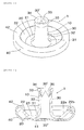
- Figs. 1 and 2 are a perspective view and a longitudinal sectional view of a button fastener (hereinafter referred to also as “fastener”) 1 in accordance with an embodiment of the present invention.
- the fastener 1 comprises a fastener body 10 and a cover member (shell) 40, each of which is formed by drawing a metal plate of brass, aluminum alloy, etc.
- the fastener body 10 includes an almost disk-like base 20 and a hollow cylindrical post 30 which extends upward from a center area of the base 20 concentrically.
- the top (34) of the post 30 (or the top face defined by the top (34)) is open as a top opening 30'.
- the post 30 has a fold-back portion 35 which is formed by folding back the metal plate making the post 30 from the top 34 radially inward and downward.
- the top 34 of the post 30 which is the proximal end of the fold-back portion 35 is formed as a sharp annular edge (hereinafter referred to also as "top edge") 34 to facilitate cutting and piercing through a fabric c at the time of mounting of a button 50 (see Fig. 4 etc.) to the fabric c as described in detail later.
- the bottom of the post 30 is open as a bottom opening 30" in the center area on the lower surface of the base 20.
- the cover member 40 is attached to the fastener body 10 so as to cover the base 20 from below.
- the bottom opening 30" is closed by the cover member 40.
- the post 30 (except for the fold-back portion 35) is divided into a post proximal portion 31 rising gradually from the base 20 and having curved longitudinal sectional (inner and outer) surfaces; a post barrel portion 32 extending upward from the post proximal portion 31 while the outer diameter of the portion 32 slightly reducing gradually and having linear longitudinal sectional (inner and outer) surfaces; and a post distal portion 33 including the top edge 34 as mentioned above and having the outer diameter which expands radially outward from the upper end of the post barrel portion 32.
- the outer diameter of the post distal portion 33 gradually expands upward from the upper end of the linear longitudinal sectional outer surface of the post barrel portion 32 up to the maximum, and then slightly reduces to the top edge 34 gradually.
- the diameter of the top edge 34 of the post 30 is greater than the outer diameter of the post barrel portion 32 throughout.
- the thickness of the post barrel portion 32, post distal portion 33 and fold-back portion 35 is gradually thinner from the lower end to the upper end of the post barrel portion 32, and then, via the post distal portion 33, from the upper end (proximal end) to the lower end (distal end) of the fold-back portion 35, except for about the top edge 34 as the turn-round part of the fold-back portion 35. Because of the thickness getting thinner from the lower end of the post barrel portion 32 to the distal end of the fold-back portion 35 like this, a load as needed to turn down the fold-back portion 35 can decrease leading to be a better workability compared with a constant thickness. With the fold-back portion 35, the thickness about the top edge 34 increases since the post distal portion 33 and the fold-back portion 35 overlap and their respective thickness is added.
- the fold-back portion 35 includes, on its inner periphery, a first inclined surface 35a with a gentle inclination, the inner diameter of which drastically decreases from the top edge 34 radially inward, and a second inclined surface 35b with a steep inclination, the inner diameter of which somewhat decreases from the radially outer end of the first inclined face 35a to the lower end of the fold-back portion 35.
- the first inclined surface 35a forms the sharp edge 34 together with the outer periphery surface of the post distal portion 33.
- the fold-back portion 35 is cut out upward from the lower end partially in a triangle form so as to facilitate decreasing the diameter toward the lower end easier.
- the length of the fold-back portion 35 in the axial direction exceeds that of the post distal portion 33 and equals approximately 1/4 of the height (the axial length) of the post 30 from the base 20.
- the base 20 includes a base bottom 21 extending radially outward from the lower end of the post proximal portion 31 horizontally, and a base flange 22 rising upward relative to the base bottom 21 radially outward from the base bottom 21.
- the base flange 22 has a flange inclined portion 22a being inclined gradually upward and radially outward from the radially outer end of the base bottom 21, and a flange horizontal portion 22b extending horizontally and radially outward from the radially outer end of the flange inclined portion 22a.
- the cover member 40 includes a disk-like, horizontal cover base 41 covering the lower surface of the base bottom 21 including the bottom opening 30" of the post 30, and a curved outer periphery 42 turning back in a C-shaped cross-section upward from the radially outer end of the cover base 41 so as to wrap around a radially outer end part of the base 20, terminating on the flange horizontal portion 22b.
- the curved outer periphery 42 rises upward beyond the flange horizontal portion 22b of the base 20.
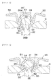
- Fig. 4 shows a state where the button 50 (here, a decorative button is exemplified), the fabric c and the button fastener 1 are arranged in the up and down direction (the radial direction) when the button 50 is fastened to the fabric c.
- the button 50 and the button fastener 1 are one embodiment of a button structure in accordance with the present invention.
- the button 50 is held by an up-and-down part of a well-known press machine, and the button fastener 1 is set on a lower die concentrically with the button 50.
- the button 50 is a well-known one as formed by drawing a metal plate.
- the button 50 includes a center projection 51 projecting upward in a dome-shape; a peripheral side 55 turning back upward and radially outward from the lower end 52 of the projection 51 and extending upward up to somewhat beyond the top of the projection 51 while expanding its outer diameter radially outward, surrounding the projection 51; and an annular flange 56 extending radially outward from the upper end of the peripheral side 55 while somewhat lowering, the radially outer end of the flange 56 being at the same height as the top of the projection 51.
- the projection 51 has a bottom opening 53 near at the lower end of the projection 51.
- a post-receiving space 54 which is a space for receiving the post 30 of the button fastener 1 through the bottom opening 53 when the button 50 is being fastened to the fabric c and then deforming the post 30 to be fixed.
- the lower end 52 of the projection 51 which is the turn-round part of the peripheral side 55, is a semicircular shape in longitudinal section, the diameter of the semicircular shape being the same length as the thickness of a double metal plate forming the button 50.
- the inner diameter of the projection 51 or the diameter of the post-receiving space 54 is at the maximum at a spot 54' above the bottom opening 53, and somewhat decreases from the maximal diameter spot 54' to the bottom opening 53 and then increases again to the lowest spot 52' of the lower end 52.
- the bottom opening 53 is at slightly above the lowest spot 52' of the lower end 52, and the inner diameter of the opening 53 is at the minimum at the bottom opening 53 slightly above the lowest spot 52'.
- the diameter of bottom opening 53 is approximately the same as that of the top edge 34 of the button fastener 1.
- the lower end 52 of the projection 51 as being a semicircular cross-section as mentioned above, can effectively hold down the fabric c when the fabric c is cut by the top edge 34 of the button fastener 1 as described later. Therefore, the lower end 52 is hereinafter referred to also as "fabric-holddown 52.”
- the button 50 When the button 50 is fastened to the fabric c using the button fastener 1, by lowering the button 50 from the state shown in Fig. 4 , the fabric c is held between the button 50 and the button fastener 1 as shown in Fig. 5 . After that, the post 30 of the button fastener 1 cuts and pierces the fabric c with the top edge 34 in the lead, and then goes into the post-receiving space 54 of the button 50. At the time immediately before cutting the fabric c in Fig.
- the fabric c is made thinner annularly by being compressed between the fabric-holddown 52 of the button 50 and the top edge 34 of the post 30 of the button fastener 1, and the radially inner portion from the annularly compressed spot is extending into the post-receiving space 54 through the bottom opening 53.
- the edge 34 relatively moves up to cut the fabric c, and at this time the first inclined surface 35a of the fold-back portion 35 of the button fastener 1 can hold the posture of the fabric c while supporting the fabric c, enhancing the effectiveness of the edge 34 and serving to help cut the fabric c smoothly by the top edge 34.
- a round piece c' cut out by the edge 34 is received within the post-receiving space 54.
- the post 30, which has gone into the post-receiving space 54 through the bottom opening 53 of the button 50 after piecing the fabric c as shown in Fig. 7 is plastically deformed so as to decrease the diameter of the top opening 30' gradually while the edge 34 is guided upward along the inner surface of the projection 51. Finally, the post 30 is compressed in the axial direction and fixed as shown in Fig. 8 .
- the fabric piece c' is taken into the post 30 through the top opening 30' of the post 30, so the fabric piece c' would not have an adverse effect on the deformation of the post 30. Because of the post distal portion 33 being radially outward expanded, the fabric piece c' can be taken into the post 30 smoothly.
- the fabric piece c' in the post 30 remains within the button fastener 1 since the bottom opening 30" is closed by the cover member 40. (See Fig. 8 ) As the fabric piece c' does not go out of the fastener 1, a work to look for and remove fabric pieces c is unnecessary after the button 50 is mounted. In the Fig. 8 state where the button-fastening is completed, the post 30 of the button fastener 1 is compressed along the inner surface of the projection 51 to conform to the shape of the post-receiving space 54, and thereby the post 30 becomes undetachable from the post-receiving space 54. As a result, the button 50 and the button fastener 1 are connected to each other with the fabric c held therebetween.
- the top opening 30' of the post 30 becomes closed, and the fabric piece c' remains in the compressed post 30. Further, the fabric c is firmly held between the flange 56 of the button 1 and the curved outer periphery 42 of the cover member 40 of the button fastener 1 and is made thinner due to the compression. Since the curved outer periphery 42 lies upward further than the flange horizontal portion 22b which rises upward rather than the base bottom 21 of the base 20, the curved outer periphery 42 can be close to the flange 56, which makes it possible to surely fasten the button 50 to the fabric c as being thin.
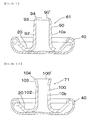
- Figs. 9 to 11 are sectional views showing button fasteners 61, 71, 81 in accordance with another embodiment of the present invention.
- These fasteners 61, 71, 81 comprise a fastener body 10a, 10b, 10c and a cover member 40 (this cover member is identical with that in the button fastener 1, so the same reference number is used).
- the fastener body 10a, 10b, 10c there are differences from the button fastener 1 substantially only in their post distal portions and whether a fold-back portion exists. Therefore, in Figs. 9 to 11 , the same reference number 20 is also used to the base as in Fig. 1 etc.
- the post 90 of the fastener 61 as shown in Fig. 9 extends from the proximal end to the distal end linearly in longitudinal section while the outer diameter slightly decreases gradually.
- the post 90 has the top opening 90'.
- the post distal portion 93 does not expand radially outward relative to the post barrel portion 92, and a fold-back portion is not provided.
- the post distal portion 103 expands radially outward with the outer diameter gradually increasing the outer diameter upward from the upper end of the post barrel portion 102. Thereby, the top opening 100' enlarges, making the capture of the fabric piece c' easily.
- the upper end of the post 100 is formed as a edge 104, and the diameter of the edge 104 is larger than the outer diameter of the post barrel portion 102.
- a fold-back portion is not provided.
- the post 110 of the fastener 81 as shown in Fig. 11 includes the post distal portion 113 which expands radially outward rather than the post barrel portion 112 as with the fastener 1.
- the post 110 is different from the fastener 1 only in the fold-back portions.
- the fold-back portion 115 extends from the top edge 114 of the post 110 radially inward and downward while gently inclining.
- the fold-back portion 115 can open radially outward and downward, through which the fabric piece c' is taken into the post 110.
- the posts 90, 100, 110 of the fastener 61, 71, 82 include the same bottom openings 30" as in the post 30 of the fastener 1.
- Fig. 12 is an illustrative sectional view, similar to Fig. 8 , showing a state where a decorative button 120, which is a different type from the button 50, has been fastened to the fabric c using the button fastener 1 (this fastener is substantially the same as that in Fig. 1 etc., so the same reference numbers as to the fastener 1 are used).
- the button 120 includes a projection 121 projecting upward and an annular flange 126 extending radially outward from the projection 121. There is defined a post-receiving space 124 in the projection 121.
- the post 30 of the button fastener 1 is deformed and fixed within the post-receiving space 124, and the fabric c is held between the flange 126 of the button 120 and the curved outer periphery 42 of the button fastener 1. Further, the fabric piece c" is captured in the post 30.
- the fastener 61, 71, 82 can also be used as a button fastener with respect to the button 120.
- Fig. 13 is an illustrative sectional view, similar to Fig. 8 , showing a state where a button 130 as a male snap has been fastened to the fabric c using the button fastener 1 (this fastener is substantially the same as that in Fig. 1 etc., so the same reference numbers as to the fastener 1 are used).
- the button 130 includes a projection 131 projecting upward, which detachably engages with a depression of a female snap (not shown), and an annular flange 136 extending radially outward from the projection 131. There is defined a post-receiving space 134 in the projection 131.
- the post 30 of the button fastener 1 is deformed and fixed within the post-receiving space 134, and the fabric c is held between the flange 136 of the button 130 and the curved outer periphery 42 of the button fastener 1. Further, the fabric piece c" (since it is the same as in Fig. 12 , the same reference number is used) is captured in the post 30.
- the fastener 61, 71, 82 can also be used.
Landscapes
- Slide Fasteners, Snap Fasteners, And Hook Fasteners (AREA)
- Toys (AREA)
Abstract
Provided is a button fastener (1, 61, 71, 81) which can surely fasten a button (50, 120, 130) to a fabric (c) even if the fabric (c) is thin when the button (50, 120, 130) is fastened to the fabric (c), and in which fabric pieces (c', c") do not have an adverse effect on the button-fastening and a work to remove fabric pieces (c', c") is unnecessary. The button fastener (1, 61, 71, 81) comprises a fastener body (10, 10a, 10b, 10c) and a cover member (40) which is attached to the fastener body (10, 10a, 10b, 10c). The fastener body (10, 10a, 10b, 10c) includes a disk-like base (20) and a hollow, cylindrical post (30, 90, 100, 110) extending upward from a center area of the base (20) concentrically. The post (30, 90, 100, 110) has a top opening (30', 90', 100', 110') at its upper end (34, 94, 104, 114) and a bottom opening (30") in a center area of the base (20). The cover member (40) covers the lower surface of the base (20) including the bottom opening (30"). The base (20) includes a base bottom (21) adjacent to the post (30, 90, 100, 110) and a base flange (22) rising upward relative to the base bottom (21) radially outward from the base bottom (21). The cover member (40) includes a curved outer periphery (42) curving from the lower surface side of the base (20) and then rising upward beyond the base flange (22) of the base (20). The upper end (34, 104, 114) of the post (30, 100, 110) may be formed as an edge (34, 104, 114) which is able to cut the fabric (c) against the button (50, 120, 130) when the button (50, 120, 130) is fastened to the fabric (c). The post (30, 110) may include a fold-back portion (35, 115) which is folded back radially inward and downward from the upper end (34, 114) of the post.
Description
- This invention relates to a button fastener and a button structure, and more specifically, to a button fastener to fasten a button such as a decorative button, a snap button to a fabric, and a button structure composed of a button and a button fastener.
- As a combination of a button and a button fastener to fasten the button to a fabric, a type has been known where a button is fastened to a fabric by deforming and fixing a post of a button fastener within a post-receiving space or an inside space of a projection of the button, after the post has pierced the fabric to be received in the space, as shown in Japanese Examined Utility Model Application Publication No.
S60-8724 2005-204911 - However, with conventional buttons and button fasteners, when a fabric is thin, it would be unable to firmly hold the fabric between the flange of a button and the base of a button fastener, and there would be a case that a button cannot be surely fastened to a fabric. Further, as a post of a button fastener pierces a fabric to fasten a button to the fabric, a round piece of the fabric arises. With common button fasteners, the piece would go into the post-receiving space of the button, which could hamper a deformation of the post, have an adverse effect on the connection between the button and the button fastener, and necessitate an additional work to remove fabric pieces after a button mounting work.
-
- [Patent document 1] Japanese Examined Utility Model Application Publication No.
S60-8724 - [Patent document 2] Japanese Published Patent Application No.
2005-204911 - An object of the invention as made in view of the above-mentioned problems is to provide a button fastener and a button structure which can surely fasten a button to a fabric even if the fabric is thin.
- Another object of the invention is to provide a button fastener and a button structure in which fabric pieces, which arise at the time of fastening the button to the fabric, do not have an adverse effect on the button-fastening, and a work to remove fabric pieces is unnecessary.
- To solve the problems, according to the present invention, there is provided a button fastener for fastening a button to a fabric, comprising: a fastener body including a disk-like base and a post which extends upward from a center area of the base concentrically; and a cover member which is attached to the fastener body so as to cover the lower surface of the base; wherein said base includes a base bottom adjacent to the post and a base flange rising upward relative to the base bottom radially outward from the base bottom; wherein said cover member includes a curved outer periphery curving from the lower surface side of the base and then rising upward beyond the base flange of the base.
- In the invention, when the button is being fastened to the fabric, the fabric is held between the button and the curved outer periphery of the cover member of the button fastener. Here, since the curved outer periphery of the button fastener lies upward further than the base flange which rises upward in the base of the fastener body, the interval between the button and the curved outer periphery which face each other holding the fabric therebetween at the time of fastening the button can be narrower, which makes it possible to surely fasten the button to a thinner fabric.
- In an embodiment of the invention, said post is hollow and cylindrical and includes a top opening which is open at the upper end of the post and a bottom opening which is open in a center area of the base. When the button is fastened to the fabric, the post of the button fastener cuts and pierces the fabric bringing about a round piece of the fabric. This fabric piece can be taken in the interior of the post through its top opening, so the fabric piece could not hamper a deformation of the post. Further, since the cover member covers the lower surface of the base of the fastener body closing the bottom opening, the fabric piece, which has arisen at the time of fastening the button to the fabric, is not discharged out of the post through the bottom opening, staying within the post after it is captured in the post.
- The fastener body and the cover member in the invention can be formed such as by drawing a metal plate of e.g. aluminum, iron, stainless alloy, copper alloy including brass.
- In an embodiment of the invention, said upper end of the post is formed as an edge which is able to cut the fabric against the button when the button is fastened to the fabric. By making the upper end of the post an edge, the fabric can be cut and pierced by the post smoothly.
- In an embodiment of the invention, said post includes a fold-back portion which is folded back radially inward and downward from the upper end of the post. The fold-back portion can serve to reinforce an upper part of the post and to enhance the effectiveness of the edge at the upper end of the post.
- In an embodiment of the invention, said fold-back portion includes, on its inner periphery, a first inclined surface which gently inclines radially inward and downward from the upper end of the post and a second inclined surface which steeply inclines radially inward and downward from the radially inner end of the first inclined surface. The first inclined surface forms the top edge together with the outer periphery surface of the upper part of the post. In addition, at the time immediately before the edge of the post cuts the fabric, the first inclined surface can hold the posture of the fabric while pressing the fabric against the button side, enhancing the effect of the edge and serving to help cut the fabric smoothly.
- In an embodiment of the invention, said post includes a post proximal portion adjacent to the base, a post distal end including the upper end, and a post barrel portion linearly extending between the post proximal portion and the post distal portion, wherein the outer diameter of the post distal portion expands radially outward from the upper end of the post barrel portion, and the maximal outer diameter of the post distal portion is greater than the outer diameter of the post barrel portion. In this way, by expanding the post distal portion radially outward rather than the post barrel portion, the top opening enlarges so that the fabric piece cut out by the upper end of the post at the time of fastening the button to the fabric can be easily captured into the post.
- In an embodiment of the invention, the thickness of the post barrel portion, post distal portion and fold-back portion is gradually thinner from the lower end to the upper end of the post barrel portion, and then, via the post distal portion, from the upper end to the lower end of the fold-back portion, except for about the upper end of the post as the turn-round part of the fold-back portion. In this way, by gradually thinning down the post barrel portion, the post distal portion and the fold-back portion in this sequence, a load as needed to turn down the fold-back portion can decrease compared with a constant thickness.
- According to the second present invention, there is provided a button structure composed of a button and a button fastener for fastening the button to a fabric, the button fastener comprising: a fastener body including a disk-like base and a post which extends upward from a center area of the base concentrically; and a cover member which is attached to the fastener body so as to cover the lower surface of the base; wherein said base includes a base bottom adjacent to the post and a base flange rising upward relative to the base bottom radially outward from the base bottom; wherein said cover member includes a curved outer periphery curving from the lower surface side of the base and then rising upward beyond the base flange of the base; wherein said button includes a projection projecting upward and an annular flange extending radially outward from the projection; wherein said projection defines a post-receiving space in the interior thereof for receiving, deforming and fixing the post which has pierced the fabric; wherein said flange, in the state where the button has been fastened to the fabric with the post fixed in the post-receiving space, faces the curved outer periphery with the fabric held between the flange and the curved outer periphery.
- In the invention, when the button is being fastened to the fabric, the fabric is held between the flange of the button and the curved outer periphery of the cover member of the button fastener. Here, since the curved outer periphery of the button fastener lies upward further than the base flange which rises upward in the base of the fastener body, the interval between the flange of the button and the curved outer periphery which face each other holding the fabric therebetween at the time of fastening the button can be narrower, which makes it possible to surely fasten the button to a thinner fabric.
- In an embodiment of the invention, said post is hollow and cylindrical and includes a top opening which is open at the upper end of the post and a bottom opening which is open in a center area of the base. When the button is fastened to the fabric, the post of the button fastener cuts and pierces the fabric bringing about a round piece of the fabric. This fabric piece can be taken in the interior of the post through its top opening, so the fabric piece could not hamper a deformation of the post. Further, since the cover member covers the lower surface of the base of the fastener body closing the bottom opening, the fabric piece, which has arisen at the time of fastening the button to the fabric, is not discharged out of the post through the bottom opening, staying within the post after it is captured in the post.
- In the inventions, the button fastener comprises the fastener body and the cover member, and the curved outer periphery of the cover member lies upward further than the base flange which rises upward in the base of the fastener body, the interval between the curved outer periphery of the button fastener and (the flange of) the button which hold the fabric therebetween in the state where the button has been fastened to the fabric, which makes it possible to surely fasten the button to a thinner fabric.
- Further, since the fabric piece, which arises as the post of the button fastener cuts and pierces the fabric when the button is being fastened to the fabric, can be taken in the interior of the post through its top opening, the fabric piece could not have an adverse effect on a deformation of the post and the connection between the button and the button fastener. Furthermore, in the button fastener, since the cover member covers the lower surface of the fastener body including the bottom opening of the post, the fabric piece, which has been taken in the interior of the post through of the top opening of the post, is not discharged out of the post, a work to remove fabric pieces is unnecessary.
-
-
Fig. 1 is a perspective view of a button fastener in accordance with an embodiment of the present invention. -
Fig. 2 is a longitudinal sectional view ofFig. 1 . -
Fig. 3 is an illustrative longitudinal sectional enlarged view showing the post distal portion and the fold-back portion of the button fastener. -
Fig. 4 is an illustrative cross-sectional view showing a state where the button and the fabric are arranged with respect to the fabric. -
Fig. 5 is an illustrative cross-sectional view showing a state immediately before the fabric is cut by the button fastener in the button-fastening process. -
Fig. 6 is an illustrative cross-sectional view showing a state immediately after the fabric is cut by the button fastener in the button-fastening process. -
Fig. 7 is an illustrative cross-sectional view showing a state where the button fastener is being deformed in the button-fastening process. -
Fig. 8 is an illustrative cross-sectional view showing a state where the button-fastening is completed after the button fastener is deformed in the button-fastening process. -
Fig. 9 is a longitudinal sectional view showing a button fastener in accordance with another embodiment of the present invention. -
Fig. 10 is a longitudinal sectional view showing a button fastener in accordance with another embodiment of the present invention. -
Fig. 11 is a longitudinal sectional view showing a button fastener in accordance with still another embodiment of the present invention. -
Fig. 12 is an illustrative sectional view, similar toFig. 8 , showing an example using another type of a decorative button as a button. -
Fig. 13 is an illustrative sectional view, similar toFig. 8 , showing an example using a male snap as a button. - Hereinafter, preferred embodiments of the invention will be described while referring to the drawings.
Figs. 1 and 2 are a perspective view and a longitudinal sectional view of a button fastener (hereinafter referred to also as "fastener") 1 in accordance with an embodiment of the present invention. Thefastener 1 comprises afastener body 10 and a cover member (shell) 40, each of which is formed by drawing a metal plate of brass, aluminum alloy, etc. Thefastener body 10 includes an almost disk-like base 20 and a hollowcylindrical post 30 which extends upward from a center area of thebase 20 concentrically. The top (34) of the post 30 (or the top face defined by the top (34)) is open as a top opening 30'. Thepost 30 has a fold-back portion 35 which is formed by folding back the metal plate making thepost 30 from the top 34 radially inward and downward. The top 34 of thepost 30 which is the proximal end of the fold-back portion 35 is formed as a sharp annular edge (hereinafter referred to also as "top edge") 34 to facilitate cutting and piercing through a fabric c at the time of mounting of a button 50 (seeFig. 4 etc.) to the fabric c as described in detail later. The bottom of thepost 30 is open as abottom opening 30" in the center area on the lower surface of thebase 20. Thecover member 40 is attached to thefastener body 10 so as to cover the base 20 from below. Thebottom opening 30" is closed by thecover member 40. - The post 30 (except for the fold-back portion 35) is divided into a post
proximal portion 31 rising gradually from thebase 20 and having curved longitudinal sectional (inner and outer) surfaces; apost barrel portion 32 extending upward from the postproximal portion 31 while the outer diameter of theportion 32 slightly reducing gradually and having linear longitudinal sectional (inner and outer) surfaces; and a postdistal portion 33 including thetop edge 34 as mentioned above and having the outer diameter which expands radially outward from the upper end of thepost barrel portion 32. The outer diameter of the postdistal portion 33, as shown enlarged inFig. 3 , gradually expands upward from the upper end of the linear longitudinal sectional outer surface of thepost barrel portion 32 up to the maximum, and then slightly reduces to thetop edge 34 gradually. The diameter of thetop edge 34 of thepost 30 is greater than the outer diameter of thepost barrel portion 32 throughout. The thickness of thepost barrel portion 32, postdistal portion 33 and fold-back portion 35 is gradually thinner from the lower end to the upper end of thepost barrel portion 32, and then, via the postdistal portion 33, from the upper end (proximal end) to the lower end (distal end) of the fold-back portion 35, except for about thetop edge 34 as the turn-round part of the fold-back portion 35. Because of the thickness getting thinner from the lower end of thepost barrel portion 32 to the distal end of the fold-back portion 35 like this, a load as needed to turn down the fold-back portion 35 can decrease leading to be a better workability compared with a constant thickness. With the fold-back portion 35, the thickness about thetop edge 34 increases since the postdistal portion 33 and the fold-back portion 35 overlap and their respective thickness is added. - The fold-
back portion 35 includes, on its inner periphery, a firstinclined surface 35a with a gentle inclination, the inner diameter of which drastically decreases from thetop edge 34 radially inward, and a secondinclined surface 35b with a steep inclination, the inner diameter of which somewhat decreases from the radially outer end of the firstinclined face 35a to the lower end of the fold-back portion 35. The firstinclined surface 35a forms thesharp edge 34 together with the outer periphery surface of the postdistal portion 33. The fold-back portion 35 is cut out upward from the lower end partially in a triangle form so as to facilitate decreasing the diameter toward the lower end easier. The length of the fold-back portion 35 in the axial direction exceeds that of the postdistal portion 33 and equals approximately 1/4 of the height (the axial length) of thepost 30 from thebase 20. - The
base 20 includes a base bottom 21 extending radially outward from the lower end of the postproximal portion 31 horizontally, and abase flange 22 rising upward relative to the base bottom 21 radially outward from thebase bottom 21. Thebase flange 22 has a flangeinclined portion 22a being inclined gradually upward and radially outward from the radially outer end of the base bottom 21, and a flangehorizontal portion 22b extending horizontally and radially outward from the radially outer end of the flange inclinedportion 22a. Thecover member 40 includes a disk-like,horizontal cover base 41 covering the lower surface of the base bottom 21 including thebottom opening 30" of thepost 30, and a curvedouter periphery 42 turning back in a C-shaped cross-section upward from the radially outer end of thecover base 41 so as to wrap around a radially outer end part of thebase 20, terminating on the flangehorizontal portion 22b. The curvedouter periphery 42 rises upward beyond the flangehorizontal portion 22b of thebase 20. -
Fig. 4 shows a state where the button 50 (here, a decorative button is exemplified), the fabric c and thebutton fastener 1 are arranged in the up and down direction (the radial direction) when thebutton 50 is fastened to the fabric c. Thebutton 50 and thebutton fastener 1 are one embodiment of a button structure in accordance with the present invention. In the state ofFig. 4 , although not shown in the drawings, thebutton 50 is held by an up-and-down part of a well-known press machine, and thebutton fastener 1 is set on a lower die concentrically with thebutton 50. Thebutton 50 is a well-known one as formed by drawing a metal plate. Thebutton 50 includes acenter projection 51 projecting upward in a dome-shape; aperipheral side 55 turning back upward and radially outward from thelower end 52 of theprojection 51 and extending upward up to somewhat beyond the top of theprojection 51 while expanding its outer diameter radially outward, surrounding theprojection 51; and anannular flange 56 extending radially outward from the upper end of theperipheral side 55 while somewhat lowering, the radially outer end of theflange 56 being at the same height as the top of theprojection 51. Theprojection 51 has abottom opening 53 near at the lower end of theprojection 51. There is defined apost-receiving space 54, which is a space for receiving thepost 30 of thebutton fastener 1 through thebottom opening 53 when thebutton 50 is being fastened to the fabric c and then deforming thepost 30 to be fixed. Thelower end 52 of theprojection 51, which is the turn-round part of theperipheral side 55, is a semicircular shape in longitudinal section, the diameter of the semicircular shape being the same length as the thickness of a double metal plate forming thebutton 50. The inner diameter of theprojection 51 or the diameter of thepost-receiving space 54 is at the maximum at a spot 54' above thebottom opening 53, and somewhat decreases from the maximal diameter spot 54' to thebottom opening 53 and then increases again to the lowest spot 52' of thelower end 52. That is, thebottom opening 53 is at slightly above the lowest spot 52' of thelower end 52, and the inner diameter of theopening 53 is at the minimum at thebottom opening 53 slightly above the lowest spot 52'. The diameter ofbottom opening 53 is approximately the same as that of thetop edge 34 of thebutton fastener 1. Thelower end 52 of theprojection 51, as being a semicircular cross-section as mentioned above, can effectively hold down the fabric c when the fabric c is cut by thetop edge 34 of thebutton fastener 1 as described later. Therefore, thelower end 52 is hereinafter referred to also as "fabric-holddown 52." - When the
button 50 is fastened to the fabric c using thebutton fastener 1, by lowering thebutton 50 from the state shown inFig. 4 , the fabric c is held between thebutton 50 and thebutton fastener 1 as shown inFig. 5 . After that, thepost 30 of thebutton fastener 1 cuts and pierces the fabric c with thetop edge 34 in the lead, and then goes into thepost-receiving space 54 of thebutton 50. At the time immediately before cutting the fabric c inFig. 5 , the fabric c is made thinner annularly by being compressed between the fabric-holddown 52 of thebutton 50 and thetop edge 34 of thepost 30 of thebutton fastener 1, and the radially inner portion from the annularly compressed spot is extending into thepost-receiving space 54 through thebottom opening 53. From this state, theedge 34 relatively moves up to cut the fabric c, and at this time the firstinclined surface 35a of the fold-back portion 35 of thebutton fastener 1 can hold the posture of the fabric c while supporting the fabric c, enhancing the effectiveness of theedge 34 and serving to help cut the fabric c smoothly by thetop edge 34. A round piece c' cut out by theedge 34 is received within thepost-receiving space 54. - The
post 30, which has gone into thepost-receiving space 54 through thebottom opening 53 of thebutton 50 after piecing the fabric c as shown inFig. 7 is plastically deformed so as to decrease the diameter of the top opening 30' gradually while theedge 34 is guided upward along the inner surface of theprojection 51. Finally, thepost 30 is compressed in the axial direction and fixed as shown inFig. 8 . At the time ofFig. 7 , the fabric piece c' is taken into thepost 30 through the top opening 30' of thepost 30, so the fabric piece c' would not have an adverse effect on the deformation of thepost 30. Because of the postdistal portion 33 being radially outward expanded, the fabric piece c' can be taken into thepost 30 smoothly. The fabric piece c' in thepost 30 remains within thebutton fastener 1 since thebottom opening 30" is closed by thecover member 40. (SeeFig. 8 ) As the fabric piece c' does not go out of thefastener 1, a work to look for and remove fabric pieces c is unnecessary after thebutton 50 is mounted. In theFig. 8 state where the button-fastening is completed, thepost 30 of thebutton fastener 1 is compressed along the inner surface of theprojection 51 to conform to the shape of thepost-receiving space 54, and thereby thepost 30 becomes undetachable from thepost-receiving space 54. As a result, thebutton 50 and thebutton fastener 1 are connected to each other with the fabric c held therebetween. In the fastening completed state, the top opening 30' of thepost 30 becomes closed, and the fabric piece c' remains in thecompressed post 30. Further, the fabric c is firmly held between theflange 56 of thebutton 1 and the curvedouter periphery 42 of thecover member 40 of thebutton fastener 1 and is made thinner due to the compression. Since the curvedouter periphery 42 lies upward further than the flangehorizontal portion 22b which rises upward rather than thebase bottom 21 of thebase 20, the curvedouter periphery 42 can be close to theflange 56, which makes it possible to surely fasten thebutton 50 to the fabric c as being thin. -
Figs. 9 to 11 are sectional views showingbutton fasteners fasteners fastener body button fastener 1, so the same reference number is used). In thefastener body button fastener 1 substantially only in their post distal portions and whether a fold-back portion exists. Therefore, inFigs. 9 to 11 , thesame reference number 20 is also used to the base as inFig. 1 etc. - The
post 90 of thefastener 61 as shown inFig. 9 extends from the proximal end to the distal end linearly in longitudinal section while the outer diameter slightly decreases gradually. Thepost 90 has the top opening 90'. The postdistal portion 93 does not expand radially outward relative to thepost barrel portion 92, and a fold-back portion is not provided. In thepost 100 of thefastener 71 as shown inFig. 10 , the postdistal portion 103 expands radially outward with the outer diameter gradually increasing the outer diameter upward from the upper end of the post barrel portion 102. Thereby, the top opening 100' enlarges, making the capture of the fabric piece c' easily. The upper end of thepost 100 is formed as aedge 104, and the diameter of theedge 104 is larger than the outer diameter of the post barrel portion 102. A fold-back portion is not provided. Thepost 110 of thefastener 81 as shown inFig. 11 includes the postdistal portion 113 which expands radially outward rather than thepost barrel portion 112 as with thefastener 1. Thepost 110 is different from thefastener 1 only in the fold-back portions. The fold-back portion 115 extends from thetop edge 114 of thepost 110 radially inward and downward while gently inclining. In this case, when thepost 110 is being deformed within thepost-receiving space 54 at the time of mounting thebutton 50 to the fabric c, although not shown in the drawings, the fold-back portion 115 can open radially outward and downward, through which the fabric piece c' is taken into thepost 110. Theposts fastener same bottom openings 30" as in thepost 30 of thefastener 1. -
Fig. 12 is an illustrative sectional view, similar toFig. 8 , showing a state where adecorative button 120, which is a different type from thebutton 50, has been fastened to the fabric c using the button fastener 1 (this fastener is substantially the same as that inFig. 1 etc., so the same reference numbers as to thefastener 1 are used). Thebutton 120 includes aprojection 121 projecting upward and anannular flange 126 extending radially outward from theprojection 121. There is defined apost-receiving space 124 in theprojection 121. In the state where thebutton 120 has been fastened to the fabric c, thepost 30 of thebutton fastener 1 is deformed and fixed within thepost-receiving space 124, and the fabric c is held between theflange 126 of thebutton 120 and the curvedouter periphery 42 of thebutton fastener 1. Further, the fabric piece c" is captured in thepost 30. As a button fastener with respect to thebutton 120, thefastener -
Fig. 13 is an illustrative sectional view, similar toFig. 8 , showing a state where abutton 130 as a male snap has been fastened to the fabric c using the button fastener 1 (this fastener is substantially the same as that inFig. 1 etc., so the same reference numbers as to thefastener 1 are used). Thebutton 130 includes aprojection 131 projecting upward, which detachably engages with a depression of a female snap (not shown), and anannular flange 136 extending radially outward from theprojection 131. There is defined apost-receiving space 134 in theprojection 131. In the state where thebutton 130 has been fastened to the fabric c, thepost 30 of thebutton fastener 1 is deformed and fixed within thepost-receiving space 134, and the fabric c is held between theflange 136 of thebutton 130 and the curvedouter periphery 42 of thebutton fastener 1. Further, the fabric piece c" (since it is the same as inFig. 12 , the same reference number is used) is captured in thepost 30. As a button fastener with respect to thebutton 130, thefastener -
- 1, 61, 71, 81
- button fastener
- 10, 10a, 10b, 10c
- fastener body
- 20
- base
- 22b
- flange horizontal portion
- 30, 90, 100, 110
- post
- 30', 90', 100', 110'
- top opening
- 30"
- bottom opening
- 31
- post proximal portion
- 32, 92, 102, 112
- post barrel portion
- 33, 93, 103, 113
- post distal portion
- 34, 94, 104, 114
- upper end of post
- 34, 104, 114
- edge
- 35, 115
- fold-back portion
- 35a
- first inclined surface
- 35b
- second inclined surface
- 40
- cover member (shell)
- 42
- urved outer periphery
- 50, 120, 130
- button
- 51, 121, 131
- projection
- 52
- lower end of semicircular part (fabric-holddown)
- 53
- bottom opening
- 54, 124, 134
- post-receiving space
- 56, 126, 136
- flange
- c
- fabric
- c', c"
- fabric piece
Claims (9)
- A button fastener (1, 61, 71, 81) for fastening a button (50, 120, 130) to a fabric (c), comprising:a fastener body (10, 10a, 10b, 10c) including a disk-like base (20) and a post (30, 90, 100, 110) which extends upward from a center area of the base (20) concentrically; anda cover member (40) which is attached to the fastener body (10, 10a, 10b, 10c) so as to cover the lower surface of the base (20);wherein said base (20) includes a base bottom (21) adjacent to the post (30, 90, 100, 110) and a base flange (22) rising upward relative to the base bottom (21) radially outward from the base bottom (21);wherein said cover member (40) includes a curved outer periphery (42) curving from the lower surface side of the base (20) and then rising upward beyond the base flange (22) of the base (20).
- The button fastener according to claim 1, wherein said post (30, 90, 100, 110) is hollow and cylindrical and includes a top opening (30', 90', 100', 110') which is open at the upper end (34, 94, 104, 114) of the post and a bottom opening (30") which is open in a center area of the base (20).
- The button fastener according to claim 1, wherein said upper end (34, 104, 114) of the post (30, 100, 110) is formed as a edge (34, 104, 114) which is able to cut the fabric (c) against the button (50, 120, 130) when the button (50, 120, 130) is fastened to the fabric (c).
- The button fastener according to claim 3, wherein said post (30, 110) includes a fold-back portion (35, 115) which is folded back radially inward and downward from the upper end (34, 114) of the post.
- The button fastener according to claim 4, wherein said fold-back portion (35) includes, on its inner periphery, a first inclined surface (35a) which gently inclines radially inward and downward from the upper end (34) of the post (30) and a second inclined surface (35b) which steeply inclines radially inward and downward from the radially inner end of the first inclined surface (35a).
- The button fastener according to any of claims 1 to 5, wherein said post (30, 100, 110) includes a post proximal portion (31) adjacent to the base (20), a post distal end (33, 101, 113) including the upper end, and a post barrel portion (32 102, 112) linearly extending between the post proximal portion (31) and the post distal portion (33 103, 113), wherein the outer diameter of the post distal portion (33 103, 113) expands radially outward from the upper end of the post barrel portion (32 102, 112), and the maximal outer diameter of the post distal portion (33 103, 113) is greater than the outer diameter of the post barrel portion (32 102, 112).
- The button fastener according to claim 6, wherein the thickness of the post barrel portion (32, 112), post distal portion (33, 113) and fold-back portion (35, 115) is gradually thinner from the lower end to the upper end of the post barrel portion (32, 112), and then, via the post distal portion (33, 113), from the upper end to the lower end of the fold-back portion (35, 115), except for about the upper end (34, 114) of the post (30, 110) as the turn-round part of the fold-back portion (35, 115).
- A button structure composed of a button (50, 120, 130) and a button fastener (1, 61, 71, 81) for fastening the button (50, 120, 130) to a fabric (c), the button fastener (1, 61, 71, 81) comprising:a fastener body (10, 10a, 10b, 10c) including a disk-like base (20) and a post (30, 90, 100, 110) which extends upward from a center area of the base (20) concentrically; anda cover member (40) which is attached to the fastener body (10, 10a, 10b, 10c) so as to cover the lower surface of the base (20);wherein said base (20) includes a base bottom (21) adjacent to the post (30, 90, 100, 110) and a base flange (22) rising upward relative to the base bottom (21) radially outward from the base bottom (21);wherein said cover member (40) includes a curved outer periphery (42) curving from the lower surface side of the base (20) and then rising upward beyond the base flange (22) of the base (20);wherein said button (50, 120, 130) includes a projection (51, 121, 131) projecting upward and an annular flange (56, 126, 136) extending radially outward from the projection (51, 121, 131);wherein said projection (51, 121, 131) defines a post-receiving space (54, 124, 134) in the interior thereof for receiving, deforming and fixing the post (30, 90, 100, 110) which has pierced the fabric (c);wherein said flange (56, 126, 136), in the state where the button has been fastened to the fabric with the post (30, 90, 100, 110) fixed in the post-receiving space (54, 124, 134), faces the curved outer periphery (42) with the fabric (c) held between the flange and the curved outer periphery (42).
- The button structure according to claim 8, wherein said post (30, 90, 100, 110) is hollow and cylindrical and includes a top opening (30', 90', 100', 110') which is open at the upper end (34, 94, 104, 114) of the post (30, 90, 100, 110) and a bottom opening (30") which is open in a center area of the base (20).
Applications Claiming Priority (1)
| Application Number | Priority Date | Filing Date | Title |
|---|---|---|---|
| PCT/JP2009/070833 WO2011074053A1 (en) | 2009-12-14 | 2009-12-14 | Button fastener and button structure |
Publications (1)
| Publication Number | Publication Date |
|---|---|
| EP2514334A1 true EP2514334A1 (en) | 2012-10-24 |
Family
ID=44166855
Family Applications (1)
| Application Number | Title | Priority Date | Filing Date |
|---|---|---|---|
| EP09852249A Withdrawn EP2514334A1 (en) | 2009-12-14 | 2009-12-14 | Button fastener and button structure |
Country Status (5)
| Country | Link |
|---|---|
| US (1) | US20120246881A1 (en) |
| EP (1) | EP2514334A1 (en) |
| JP (1) | JPWO2011074053A1 (en) |
| CN (1) | CN102753051A (en) |
| WO (1) | WO2011074053A1 (en) |
Cited By (3)
| Publication number | Priority date | Publication date | Assignee | Title |
|---|---|---|---|---|
| EP3238562A4 (en) * | 2014-12-25 | 2018-05-23 | Duraflex Hong Kong Limited | Snap fastener |
| FR3059062A1 (en) * | 2016-11-22 | 2018-05-25 | Airbus Operations | SELF-PROPELLED INSULATION MATTRESS FOR AIRCRAFT INSULATION MATTRESS, METHOD OF INSTALLING SAID SPACER AND AIRCRAFT INSULATION MATTRESS EQUIPPED WITH SAID SPACER |
| EP3348162A4 (en) * | 2015-09-11 | 2019-04-10 | YKK Corporation | BUTTON PRESSURE |
Families Citing this family (7)
| Publication number | Priority date | Publication date | Assignee | Title |
|---|---|---|---|---|
| JP2013043004A (en) * | 2011-08-25 | 2013-03-04 | Ykk Corp | Punch, device, and method for attaching button |
| CN103763966B (en) * | 2011-09-02 | 2016-09-21 | Ykk株式会社 | Outer enclosure body, fixture, button and the fixing means of fixing object |
| US9089186B1 (en) | 2013-06-05 | 2015-07-28 | Susan McCloskey | Button restraint system and method thereof |
| CN204617239U (en) * | 2015-04-28 | 2015-09-09 | 达基工业有限公司 | Urgent knot |
| KR101660504B1 (en) * | 2015-10-19 | 2016-09-27 | 임형천 | A male button for snap button |
| CN107568844B (en) * | 2016-07-04 | 2020-07-10 | Ykk株式会社 | Button assembling device and defective product detection method |
| JP7198372B2 (en) * | 2019-12-13 | 2022-12-28 | Ykk株式会社 | Fixture for button |
Family Cites Families (15)
| Publication number | Priority date | Publication date | Assignee | Title |
|---|---|---|---|---|
| US1873891A (en) * | 1930-11-07 | 1932-08-23 | United Carr Fastener Corp | Snap fastener member |
| US3320644A (en) * | 1965-04-09 | 1967-05-23 | Scovill Manufacturing Co | Tack-fastened button |
| US3613181A (en) * | 1970-08-26 | 1971-10-19 | Scovill Manufacturing Co | Snap fastener socket |
| JPS608724Y2 (en) * | 1978-04-18 | 1985-03-28 | モリト株式会社 | clothing rivets |
| JPS5921207U (en) * | 1982-08-02 | 1984-02-09 | 日本ノ−シヨン工業株式会社 | Caulking metal fittings for caulking type buttons |
| JPS6342818Y2 (en) * | 1984-10-22 | 1988-11-09 | ||
| JPS61136914U (en) * | 1985-02-14 | 1986-08-26 | ||
| JPH0227769Y2 (en) * | 1985-10-04 | 1990-07-26 | ||
| JPH0437450Y2 (en) * | 1987-10-23 | 1992-09-03 | ||
| JP3046971B2 (en) * | 1992-11-30 | 2000-05-29 | ワイケイケイ株式会社 | Female body of snap button and crimping type |
| ITPD950062A1 (en) * | 1995-03-24 | 1996-09-24 | Riccardo Candotti | MALE COMPONENT OF SNAP BUTTON PARTICULARLY FOR CLOTHING ITEMS |
| JPH09224718A (en) * | 1996-02-21 | 1997-09-02 | Shimamura Kinzoku Kogyo Kk | Metal fittings for snap side and method of manufacturing the same |
| DE19638450C1 (en) * | 1996-09-19 | 1997-11-20 | Stocko Fasteners Gmbh | Cap rivet for attaching especially press-button fastening |
| DE19834458C2 (en) * | 1998-07-30 | 2001-09-13 | Stocko Fasteners Gmbh | Cap rivet |
| JP2005204911A (en) * | 2004-01-22 | 2005-08-04 | Ykk Corp | button |
-
2009
- 2009-12-14 EP EP09852249A patent/EP2514334A1/en not_active Withdrawn
- 2009-12-14 CN CN2009801634425A patent/CN102753051A/en active Pending
- 2009-12-14 US US13/514,629 patent/US20120246881A1/en not_active Abandoned
- 2009-12-14 WO PCT/JP2009/070833 patent/WO2011074053A1/en not_active Ceased
- 2009-12-14 JP JP2011545863A patent/JPWO2011074053A1/en active Pending
Non-Patent Citations (1)
| Title |
|---|
| See references of WO2011074053A1 * |
Cited By (7)
| Publication number | Priority date | Publication date | Assignee | Title |
|---|---|---|---|---|
| EP3238562A4 (en) * | 2014-12-25 | 2018-05-23 | Duraflex Hong Kong Limited | Snap fastener |
| EP3348162A4 (en) * | 2015-09-11 | 2019-04-10 | YKK Corporation | BUTTON PRESSURE |
| US10986901B2 (en) | 2015-09-11 | 2021-04-27 | Ykk Corporation | Snap button |
| US11969060B2 (en) | 2015-09-11 | 2024-04-30 | Ykk Corporation | Snap button |
| FR3059062A1 (en) * | 2016-11-22 | 2018-05-25 | Airbus Operations | SELF-PROPELLED INSULATION MATTRESS FOR AIRCRAFT INSULATION MATTRESS, METHOD OF INSTALLING SAID SPACER AND AIRCRAFT INSULATION MATTRESS EQUIPPED WITH SAID SPACER |
| EP3333067A1 (en) * | 2016-11-22 | 2018-06-13 | Airbus Operations S.A.S. | Self-piercing spacer, installation process of the self-piercing spacer in an insulating mat and insulating mat of an aircraft equipped with the self-piercing spacer |
| US10457377B2 (en) | 2016-11-22 | 2019-10-29 | Airbus Operations S.A.S. | Self-perforating spacer for an insulation blanket of an aircraft, assembly method for said spacer and insulation blanket for an aircraft fitted with said spacer |
Also Published As
| Publication number | Publication date |
|---|---|
| JPWO2011074053A1 (en) | 2013-04-25 |
| CN102753051A (en) | 2012-10-24 |
| US20120246881A1 (en) | 2012-10-04 |
| WO2011074053A1 (en) | 2011-06-23 |
Similar Documents
| Publication | Publication Date | Title |
|---|---|---|
| US20120246881A1 (en) | Button Fastener and Button Structure | |
| JP6181766B2 (en) | Cap, buttons, and button forming method | |
| US20130294860A1 (en) | Functional element, a component assembly consisting of a functional element and a sheet metal part and also a method for the attachment of the functional element to a sheet metal part | |
| EP2540186B1 (en) | Button fixing member and method for forming button fixing member, eyelet member and method for forming eyelet member | |
| US11969060B2 (en) | Snap button | |
| JP5313359B2 (en) | Button mounting method, button mounting system, and upper mold for button mounting | |
| JP5615848B2 (en) | button | |
| EP1557107B1 (en) | Button | |
| EP2052638A2 (en) | Button | |
| JP5859030B2 (en) | Button mounting device and button holding die | |
| JP6170572B2 (en) | Button stop | |
| CN104661549B (en) | Button installation method and button | |
| JP7651322B2 (en) | Male snap button | |
| JP2007244667A (en) | Decorative button | |
| WO2024134899A1 (en) | Button member | |
| JP5731589B2 (en) | Button mounting member forming method | |
| JP5863912B2 (en) | Eyelet member forming method | |
| HK1126632B (en) | Button |
Legal Events
| Date | Code | Title | Description |
|---|---|---|---|
| PUAI | Public reference made under article 153(3) epc to a published international application that has entered the european phase |
Free format text: ORIGINAL CODE: 0009012 |
|
| 17P | Request for examination filed |
Effective date: 20120712 |
|
| AK | Designated contracting states |
Kind code of ref document: A1 Designated state(s): AT BE BG CH CY CZ DE DK EE ES FI FR GB GR HR HU IE IS IT LI LT LU LV MC MK MT NL NO PL PT RO SE SI SK SM TR |
|
| DAX | Request for extension of the european patent (deleted) | ||
| STAA | Information on the status of an ep patent application or granted ep patent |
Free format text: STATUS: THE APPLICATION IS DEEMED TO BE WITHDRAWN |
|
| 18D | Application deemed to be withdrawn |
Effective date: 20140701 |