EP2514267B1 - Method of crosstalk reduction for multi-zone induction heating systems - Google Patents
Method of crosstalk reduction for multi-zone induction heating systems Download PDFInfo
- Publication number
- EP2514267B1 EP2514267B1 EP10836898.6A EP10836898A EP2514267B1 EP 2514267 B1 EP2514267 B1 EP 2514267B1 EP 10836898 A EP10836898 A EP 10836898A EP 2514267 B1 EP2514267 B1 EP 2514267B1
- Authority
- EP
- European Patent Office
- Prior art keywords
- current
- coils
- induction coils
- phase
- power module
- Prior art date
- Legal status (The legal status is an assumption and is not a legal conclusion. Google has not performed a legal analysis and makes no representation as to the accuracy of the status listed.)
- Not-in-force
Links
- 230000006698 induction Effects 0.000 title claims description 54
- 238000010438 heat treatment Methods 0.000 title claims description 31
- 238000000034 method Methods 0.000 title claims description 30
- 230000001360 synchronised effect Effects 0.000 claims description 6
- 238000012544 monitoring process Methods 0.000 claims description 2
- 230000000977 initiatory effect Effects 0.000 claims 3
- 230000008030 elimination Effects 0.000 claims 2
- 238000003379 elimination reaction Methods 0.000 claims 2
- 230000001939 inductive effect Effects 0.000 description 5
- 230000033228 biological regulation Effects 0.000 description 3
- 230000001105 regulatory effect Effects 0.000 description 3
- 238000001514 detection method Methods 0.000 description 2
- 230000010363 phase shift Effects 0.000 description 2
- 230000001351 cycling effect Effects 0.000 description 1
- 239000000284 extract Substances 0.000 description 1
- 230000020169 heat generation Effects 0.000 description 1
- 239000000155 melt Substances 0.000 description 1
Images

Classifications
-
- H—ELECTRICITY
- H05—ELECTRIC TECHNIQUES NOT OTHERWISE PROVIDED FOR
- H05B—ELECTRIC HEATING; ELECTRIC LIGHT SOURCES NOT OTHERWISE PROVIDED FOR; CIRCUIT ARRANGEMENTS FOR ELECTRIC LIGHT SOURCES, IN GENERAL
- H05B6/00—Heating by electric, magnetic or electromagnetic fields
- H05B6/02—Induction heating
- H05B6/06—Control, e.g. of temperature, of power
- H05B6/062—Control, e.g. of temperature, of power for cooking plates or the like
- H05B6/065—Control, e.g. of temperature, of power for cooking plates or the like using coordinated control of multiple induction coils
Definitions
- the present invention generally relates generally to induction heating apparatus and, more particularly, to methods for reducing crosstalk between induction heating coils in such heating apparatus.
- Simcock U.S. Pat. No. 5,059,762 , discloses a multi-zone induction heating system which includes a plurality of inductive coil sections. Each of the inductive coil sections is associated with a respective zone of the work load. Power from a supply is applied to each one of the coil sections through a respective one of a plurality of saturable reactors. Each one of the saturable reactors is operable to shunt a proportion of supply power to its respective inductive coil section in response to a demand signal derived from the operation of the respective zone for such induction coil section. Accordingly, the temperature in each zone is regulated independently of the regulation of the other zones.
- crosstalk may then become more severe as the work coils are brought closer together.
- crosstalk increases, the reliability of the each of the power modules driving each respective one of the work coils is significantly reduced. Accordingly, a need exists to reduce crosstalk in a multi-zone induction heating system in order to provide greater reliability for the power modules.
- US6498477B1 discloses an apparatus for generating magnetic fields that includes a plurality of radiator coils and a driver circuitry that drives the coils to generate magnetic fields at a plurality of driving frequencies. Each coil is driven by a respective current that comprises a basic current at a respective one of the driving frequencies and cancellation currents at one or more of the other driving frequencies so that each of the radiator coils generates a field substantially only at the respective driving frequency.
- the present invention provides a method of crosstalk reduction for a multi-zone induction heating system, according to claim 1 of the appended claims.
- the invention further provides a multi-zone induction heating system according to claim 8 of the appended claims.
- the present invention advantageously provides techniques of reducing crosstalk between work coils of a multi-zone induction heating system.
- the invention provides an induction heating apparatus including induction coil means operatively associated with a melt or other work load to be heated, where the coil is divided into a plurality of defined sections each associated with a respective zone of the workload in use.
- a power supply generates power input to the induction coil means.
- the present invention provides is a method of synchronizing the audio or higher frequency, high power currents flowing through the induction heating work coils such that the crosstalk, which is magnetic interference or energy transfer, between coils is reduced.
- the coils are driven at identical frequencies and the phase shift between them synchronized so as to minimize crosstalk between the coils.
- Crosstalk between the coils is significantly reduced when the coils are running at the exact same frequency and the phase shift between the coil currents is between - 90 and +90 degrees.
- the coils are exactly in phase, there is no crosstalk between the coils.
- Crosstalk is generally reduced to much more manageable levels as long as the phase difference between the coils does not exceed 90 degrees. This would generate reduced heating zone width as the crosstalk between coils through the roll is reduced; thus reducing widening of the coil footprints from unwanted heat generation between zones.
- the system efficiency will improve slightly as less power is required for the same amount of heating.
- a typical induction heating apparatus includes, inter alia, a power module 10, which may be exemplarily divided into five power module sections 10 a-e . It is to be recognized that any number of power module sections may be used and therefor any such number is within the scope of the present invention.
- each section 10 a-e of the power module 10 is associated with a segment of an induction work coil (not shown) to be operatively associated with a respective zone of the work load (not shown). Also as is well known in the art, each of the power module sections 10 a-e develop the work coil currents for its associated work coil.
- a common synchronizing signal 12 is sent to each of the power module sections 10 a-e .
- the synchronizing signal may be high precision synchronization pulses.
- the synchronizing signal may be communicated wirelessly or via a wire 11.
- the synchronizing signal 12 is applied to existing hardware within the power module sections 10 a-e which is responsive to the timing information provided by the synchronizing signal such that the power module sections 10 a-e are locked onto the timing information.
- Dedicated hardware within conventional power module sections 10 a-e may be provided for synchronization.
- the synchronizing signal 12 may be a synchronization pulse that is applied to each one of power module sections 10 a-e , each of which is associated with a respective one of the work coils.
- a phase of the work coil current developed from a common power source at each one of the power module sections 10 a-e is shifted such that the current applied to each respective one of the work coils is phase synchronized.
- an alternating current (AC) signal from a conventional three phase power source 15 is sent to each one of the power module sections 13 a-e via a wire 14 or wirelessly.
- the timing information used to synchronize the work coil currents may be extracted by power module sections 13 a-e from the AC signal provided by the power source 15. For example, the timing information would be of phase timing gleaned from zero-crossings of incoming three phase power or other accurately measurable instance.
- Conventional hardware within the power module sections 13 a-e can detect the time of the zero-crossing of the incoming AC power.
- the multi-zone induction heating system has a plurality work coils powered from a three phase power source which provides a synchronization pulse to each one of a plurality of power controllers, each of the power controllers being associated with a respective one of the work coils.
- a phase of a current developed from the power source at each one of the power controllers in response to the synchronization pulse shifts such that the current applied to each respective one of said work coils is phase synchronized.
- the zero crossing in the three phase power can be used to develop timing information from the detected three phase crossings.
- the synchronization pulse can be developed commensurately with the timing information.
- outputs for crosstalk distortion detection from power module sections 16 a-e are sent via wires 27 a-e or wirelessly to a processing device 28.
- the processing device 28 continuously monitors the power module sections 16 a-e to detect severe crosstalk.
- the detected crosstalk induced distortions indicate a phase difference between a module and its neighbors.
- the processing device 18 shifts the phase of the work coil current until crosstalk distortions are no longer detected.
- the distortions are detected to indicate lack of synchronization. By shifting phase until such distortion is minimized the synchronization is accomplished.
- the outputs from processing device 18 are communicated via wires 29 a-e or wirelessly to power module sections 16 a-e . Thereby, the multi-zone induction system reaches a steady-state condition with minimal crosstalk. This is an example that generally applies where all or at least a few of the power modules are already powered up.
- steady state can be achieved more quickly by powering up the individual zones associated with power module sections 16 a-e one after another so that each zone can synchronize to its neighbor without any potentially conflicting crosstalk from another neighbor.
- power module sections 16 a is first turned on without any crosstalk.
- Next power module section 16 b is turned on and locked onto the signal of power module section 16 a .
- power module section 16 c is turned on next and locked onto power modules 16 a and 16 b .
- FIG. 3 principles from the previous two methods are combined and applied to a heating system with some power modules already powered up and others not.
- An example of this is where power module sections 16 a and 16 b are powered up and power module sections 16 c , 16 d and 16 e are not powered up. If the power modules are to be powered up successively, power module section 16 c would be powered on and lock onto power module sections 16 a and 16 b .
- power module section 16 c is powered on and lock onto all previously powered on power module sections 16 a , 16 b and 16 c .
- power module section 16 e is powered on and lock onto all previously powered on power module sections 16 a , 16 b , 16 c and 16 d .
- the phase information of the originally powered on power module sections 16 a and 16 b would be constantly calibrated to minimize crosstalk between their respective work coils.
- the entire system of power module sections 16 a-e would constantly be calibrated amongst each other in order to minimize crosstalk between their respective work coils. For example, even while power module sections 16 c , 16 d and 16 e were being powered on and calibrated to already powered on power module sections 16 a and 16 b , power module sections 16 a and 16 b are also being calibrated to synchronize with all subsequently powered on power module sections 16 c , 16 d and 16 e .
- the calibration between power module sections 16 a-e to reduce crosstalk among their respective work coils could either be sequentially before or after one or more coils are powered on or simultaneously while or after one or more coils are powered on.
- the processing device 18 continuously detects in each of these currents crosstalk induced from the current in each other one of the induction coils from which crosstalk a phase difference between the current in one of the induction coils and the current in one other of the induction coils can be determined. Thereby, the phase of the current of at least one of the induction coils and another induction coil is shifted until crosstalk is substantially eliminated.
- a coil may have a current run through it initially to determine a steady state condition for it. After which, subsequent coils will be calibrated one at a time to match the same steady state of the first coil until all coils reach the same steady state condition.
- This process may initiate with a system with no currents running through the coils or with currents already running through a few coils. In the latter case, the coils with currents already running through them will also calibrate themselves to coils that subsequently have currents running through them. These processes may continue until all coils are synchronized and/or crosstalk is substantially eliminated.
- synchronizing the work coil currents precludes individual zone power level control by frequency variation.
- the methods described are particularly applicable when using duty cycling to control individual zone output power.
- This is illustrated in Fig. 4 in which unsynchronized coils practically equates to random phases between the coils, illustrated by the North (N) and South (S) polarity of the coils 20 a, b and c, which cause crosstalk 21 or significant energy flow between the coils. Indeed, heat rolls between the coils as energy flows between the coils.
- Fig. 5 illustrates an example where the coils are synchronized such that the coils 22a, b and c. are exactly in phase. This is illustrated by the North (N) and South (S) polarity of the coils 22 a, b and c. Since as there is no energy flow between the coils, there is no crosstalk between the coils 22 a, b and c.
- One method employs a common synchronizing signal, such as high frequency pulses, which would include sufficient timing information for the power modules to lock onto.
- This method uses hardware within the power modules for the synchronization of the power modules.
- the synchronization could be achieved through a wired or wireless signal.
- Another method extracts timing information from the common incoming 3-phase power. This would then be used to synchronize the work coil currents. The phase timing can be gleaned from zero-crossing of incoming power or other accurately measurable input. The difficulty with this method is the inaccurate and imprecise timing information in the common power. Additional hardware is needed to detect the time of the zero-crossing of the incoming AC power.
- Yet another method uses existing crosstalk distortion detection to nudge the phases of different work coils until the crosstalk distortions are no longer being reported.
- the inverter and/or work coil currents are continuously monitored to detect severe crosstalk. These detected crosstalk induced faults indicate a phase difference between a module and its neighbors. By slowly shifting the phase of the work coil current until crosstalk distortions are no longer detected, no synchronizing or timing signal is required.
- the multi-zone induction system reaches a steady-state condition with minimal crosstalk.
- steady state can be achieved more quickly by powering up the individual zones one after another so that each zone can synchronize to its neighbor without any potentially conflicting crosstalk from another neighbor.
- This method results in the lowest cost solution as no additional hardware is needed.
- This method is unique in that it uses the work coil currents of neighboring zones as a timing source.
Landscapes
- Physics & Mathematics (AREA)
- Electromagnetism (AREA)
- General Induction Heating (AREA)
Description
- The present application claims priority of the application for Method of Crosstalk Reduction for Multi-zone Induction Heating Systems, Application No.
61/286,798 filed December 16, 2009 - The present invention generally relates generally to induction heating apparatus and, more particularly, to methods for reducing crosstalk between induction heating coils in such heating apparatus.
- In typical induction heating systems, accurate and close control of the operating temperature of the workload is generally required. Moreover, it may become necessary for various sections of the workload to require different levels of heating such that each section of the workload must be closely controlled for accuracy.
- For example,
Simcock, U.S. Pat. No. 5,059,762 , discloses a multi-zone induction heating system which includes a plurality of inductive coil sections. Each of the inductive coil sections is associated with a respective zone of the work load. Power from a supply is applied to each one of the coil sections through a respective one of a plurality of saturable reactors. Each one of the saturable reactors is operable to shunt a proportion of supply power to its respective inductive coil section in response to a demand signal derived from the operation of the respective zone for such induction coil section. Accordingly, the temperature in each zone is regulated independently of the regulation of the other zones. - Increased precision in the temperature regulation of the work load may necessitate that the regulated zones become smaller. Smaller zones may further necessitate smaller zone spacing between inductive coil sections, thereby bringing the work coil in each section closer the work coil in neighboring sections. Since a high frequency current is applied to each work coil to develop the inductive field used to heat the work load, such field developed by one work coil may in part pass through the core of a neighboring work coil causing magnetic interference or energy transfer between coils, thereby resulting in crosstalk between coils.
- It is readily seen that crosstalk may then become more severe as the work coils are brought closer together. As crosstalk increases, the reliability of the each of the power modules driving each respective one of the work coils is significantly reduced. Accordingly, a need exists to reduce crosstalk in a multi-zone induction heating system in order to provide greater reliability for the power modules.
-
US6498477B1 discloses an apparatus for generating magnetic fields that includes a plurality of radiator coils and a driver circuitry that drives the coils to generate magnetic fields at a plurality of driving frequencies. Each coil is driven by a respective current that comprises a basic current at a respective one of the driving frequencies and cancellation currents at one or more of the other driving frequencies so that each of the radiator coils generates a field substantially only at the respective driving frequency. - The present invention provides a method of crosstalk reduction for a multi-zone induction heating system, according to claim 1 of the appended claims.
- The invention further provides a multi-zone induction heating system according to claim 8 of the appended claims.
- It is therefore an object of the present invention to reduce crosstalk in a multi-zone induction heating system in order to provide greater reliability for the power modules.
- The present invention advantageously provides techniques of reducing crosstalk between work coils of a multi-zone induction heating system. In one aspect, the invention provides an induction heating apparatus including induction coil means operatively associated with a melt or other work load to be heated, where the coil is divided into a plurality of defined sections each associated with a respective zone of the workload in use. A power supply generates power input to the induction coil means. There is also a control means for regulating the power applied to each of said sections of the work coils for regulation of the operating temperature in the respective associated zone.
- In another aspect, the present invention provides is a method of synchronizing the audio or higher frequency, high power currents flowing through the induction heating work coils such that the crosstalk, which is magnetic interference or energy transfer, between coils is reduced.
- In preferred embodiments of the present invention, the coils are driven at identical frequencies and the phase shift between them synchronized so as to minimize crosstalk between the coils. Crosstalk between the coils is significantly reduced when the coils are running at the exact same frequency and the phase shift between the coil currents is between - 90 and +90 degrees. When the coils are exactly in phase, there is no crosstalk between the coils. Crosstalk is generally reduced to much more manageable levels as long as the phase difference between the coils does not exceed 90 degrees. This would generate reduced heating zone width as the crosstalk between coils through the roll is reduced; thus reducing widening of the coil footprints from unwanted heat generation between zones. As a result, the system efficiency will improve slightly as less power is required for the same amount of heating.
- These and other objects, advantages and features of the present invention will become readily apparent to those skilled in the art form a study of the following Description of the Exemplary Preferred Embodiments when read in conjunction with the attached Drawing and appended Claims.
-
-
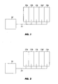
FIG. 1 illustrates the synchronization of work coil currents by a common signal. -
FIG. 2 illustrates the synchronization of work coil currents to common incoming power. -
FIG. 3 illustrates the synchronization of work coil currents by continuous phase modulation to minimize measurable crosstalk. -
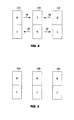
FIG. 4 illustrates how crosstalk exists when there are non-calibrated or otherwise random phases or frequencies in the induction coil. -
FIG. 5 illustrates how crosstalk is minimized or eliminated when there are calibrated or otherwise identical phases and frequencies in the induction coil. - Referring now to
Fig. 1 , a typical induction heating apparatus includes, inter alia, a power module 10, which may be exemplarily divided into five power module sections 10a-e. It is to be recognized that any number of power module sections may be used and therefor any such number is within the scope of the present invention. - As is well known in the art, each section 10a-e of the power module 10 is associated with a segment of an induction work coil (not shown) to be operatively associated with a respective zone of the work load (not shown). Also as is well known in the art, each of the power module sections 10a-e develop the work coil currents for its associated work coil.
- In accordance with the present invention, a common synchronizing
signal 12 is sent to each of the power module sections 10a-e. Exemplarily, the synchronizing signal may be high precision synchronization pulses. The synchronizing signal may be communicated wirelessly or via awire 11. The synchronizingsignal 12 is applied to existing hardware within the power module sections 10a-e which is responsive to the timing information provided by the synchronizing signal such that the power module sections 10a-e are locked onto the timing information. Dedicated hardware within conventional power module sections 10a-e may be provided for synchronization. - Exemplarily, the
synchronizing signal 12 may be a synchronization pulse that is applied to each one of power module sections 10a-e, each of which is associated with a respective one of the work coils. A phase of the work coil current developed from a common power source at each one of the power module sections 10a-e is shifted such that the current applied to each respective one of the work coils is phase synchronized. - Referring now to
Fig. 2 , another exemplary embodiment of the present invention is described. As shown inFig. 2 , an alternating current (AC) signal from a conventional threephase power source 15 is sent to each one of the power module sections 13a-e via awire 14 or wirelessly. The timing information used to synchronize the work coil currents may be extracted by power module sections 13 a-e from the AC signal provided by thepower source 15. For example, the timing information would be of phase timing gleaned from zero-crossings of incoming three phase power or other accurately measurable instance. Conventional hardware within the power module sections 13a-e can detect the time of the zero-crossing of the incoming AC power. - It is therefore apparent that the multi-zone induction heating system has a plurality work coils powered from a three phase power source which provides a synchronization pulse to each one of a plurality of power controllers, each of the power controllers being associated with a respective one of the work coils. A phase of a current developed from the power source at each one of the power controllers in response to the synchronization pulse shifts such that the current applied to each respective one of said work coils is phase synchronized.
- Furthermore, the zero crossing in the three phase power can be used to develop timing information from the detected three phase crossings. Likewise, the synchronization pulse can be developed commensurately with the timing information.
- Referring now to
Fig. 3 , yet another embodiment of the present invention is described. As shown inFig. 3 , outputs for crosstalk distortion detection from power module sections 16a-e are sent via wires 27a-e or wirelessly to aprocessing device 28. Theprocessing device 28 continuously monitors the power module sections 16a-e to detect severe crosstalk. The detected crosstalk induced distortions indicate a phase difference between a module and its neighbors. Theprocessing device 18 shifts the phase of the work coil current until crosstalk distortions are no longer detected. - As an alternative to applying a synchronizing or timing signal to maintain synchronization between work coils, as described in the present embodiment, the distortions are detected to indicate lack of synchronization. By shifting phase until such distortion is minimized the synchronization is accomplished. The outputs from processing
device 18 are communicated via wires 29a-e or wirelessly to power module sections 16a-e. Thereby, the multi-zone induction system reaches a steady-state condition with minimal crosstalk. This is an example that generally applies where all or at least a few of the power modules are already powered up. - Also in
FIG. 3 , steady state can be achieved more quickly by powering up the individual zones associated with power module sections 16 a-e one after another so that each zone can synchronize to its neighbor without any potentially conflicting crosstalk from another neighbor. For example, power module sections 16a is first turned on without any crosstalk. Next power module section 16b is turned on and locked onto the signal of power module section 16a. Likewise, power module section 16c is turned on next and locked onto power modules 16a and 16b. - The process continues until all power module sections 16a-e are powered on. Note that the number of power modules is arbitrary in number and the process continues until all power modules are powered on and locked onto all previously powered on power modules. This example generally applies where the power modules were not previously powered up.
- Additionally as shown in
FIG. 3 , principles from the previous two methods are combined and applied to a heating system with some power modules already powered up and others not. An example of this is where power module sections 16a and 16b are powered up and power module sections 16c, 16d and 16e are not powered up. If the power modules are to be powered up successively, power module section 16c would be powered on and lock onto power module sections 16a and 16b. Next, power module section 16c is powered on and lock onto all previously powered on power module sections 16a, 16b and 16c. Lastly, power module section 16e is powered on and lock onto all previously powered on power module sections 16a, 16b, 16c and 16d. - While the power module sections are being powered on successively, the phase information of the originally powered on power module sections 16a and 16b would be constantly calibrated to minimize crosstalk between their respective work coils. Likewise, the entire system of power module sections 16a-e would constantly be calibrated amongst each other in order to minimize crosstalk between their respective work coils. For example, even while power module sections 16c, 16d and 16e were being powered on and calibrated to already powered on power module sections 16a and 16b, power module sections 16a and 16b are also being calibrated to synchronize with all subsequently powered on power module sections 16c, 16d and 16e.
- Furthermore, in
FIG. 3 , the calibration between power module sections 16a-e to reduce crosstalk among their respective work coils could either be sequentially before or after one or more coils are powered on or simultaneously while or after one or more coils are powered on. - Thus, by monitoring a current through each one of a plurality of induction coils in each respective one of the power module sections 16a-e for the heating system the
processing device 18 continuously detects in each of these currents crosstalk induced from the current in each other one of the induction coils from which crosstalk a phase difference between the current in one of the induction coils and the current in one other of the induction coils can be determined. Thereby, the phase of the current of at least one of the induction coils and another induction coil is shifted until crosstalk is substantially eliminated. - This may also be done sequentially, one at a time. For example, a coil may have a current run through it initially to determine a steady state condition for it. After which, subsequent coils will be calibrated one at a time to match the same steady state of the first coil until all coils reach the same steady state condition. This process may initiate with a system with no currents running through the coils or with currents already running through a few coils. In the latter case, the coils with currents already running through them will also calibrate themselves to coils that subsequently have currents running through them. These processes may continue until all coils are synchronized and/or crosstalk is substantially eliminated.
- Furthermore, synchronizing the work coil currents precludes individual zone power level control by frequency variation. Thus the methods described are particularly applicable when using duty cycling to control individual zone output power. This is illustrated in
Fig. 4 in which unsynchronized coils practically equates to random phases between the coils, illustrated by the North (N) and South (S) polarity of the coils 20a, b and c, which cause crosstalk 21 or significant energy flow between the coils. Indeed, heat rolls between the coils as energy flows between the coils. -
Fig. 5 illustrates an example where the coils are synchronized such that the coils 22a, b and c. are exactly in phase. This is illustrated by the North (N) and South (S) polarity of the coils 22a, b and c. Since as there is no energy flow between the coils, there is no crosstalk between the coils 22a, b and c. - Various methods for synchronizing the work coil currents have been herein disclosed. One method employs a common synchronizing signal, such as high frequency pulses, which would include sufficient timing information for the power modules to lock onto. This method uses hardware within the power modules for the synchronization of the power modules. The synchronization could be achieved through a wired or wireless signal.
- Another method extracts timing information from the common incoming 3-phase power. This would then be used to synchronize the work coil currents. The phase timing can be gleaned from zero-crossing of incoming power or other accurately measurable input. The difficulty with this method is the inaccurate and imprecise timing information in the common power. Additional hardware is needed to detect the time of the zero-crossing of the incoming AC power.
- Yet another method uses existing crosstalk distortion detection to nudge the phases of different work coils until the crosstalk distortions are no longer being reported. In this method, the inverter and/or work coil currents are continuously monitored to detect severe crosstalk. These detected crosstalk induced faults indicate a phase difference between a module and its neighbors. By slowly shifting the phase of the work coil current until crosstalk distortions are no longer detected, no synchronizing or timing signal is required. The multi-zone induction system reaches a steady-state condition with minimal crosstalk.
- Additionally, steady state can be achieved more quickly by powering up the individual zones one after another so that each zone can synchronize to its neighbor without any potentially conflicting crosstalk from another neighbor. This method results in the lowest cost solution as no additional hardware is needed. This method is unique in that it uses the work coil currents of neighboring zones as a timing source.
- There has been described above a novel apparatus and methods for reducing crosstalk in multi zone induction heating systems. Those skilled in the art may now make numerous uses of, and departures from, the above described embodiments without departing from the lawfully permitted scope of the appended Claims.
Claims (8)
- A method of crosstalk reduction for a multi-zone induction heating system comprising the steps of:monitoring a current in each one of a plurality of induction coils (17, 19) associated with a respective one of a plurality of power module sections (10, 13, 16) in the heating system wherein a frequency of the current in each one of the induction coils (17, 19) is substantially similar;detecting continuously in each current a distortion developed by a phase difference of the current in an adjacent one of the induction coils (17, 19); andshifting a phase of the current in one of the induction coils (17, 19) in which the distortion is detected with respect to the phase in the adjacent one of the induction coils (17, 19) until the distortion is substantially eliminated whereby crosstalk therebetween is reduced.
- A method of crosstalk reduction for a multi-zone induction heating system as set forth in Claim 1 further comprising the steps of:initiating the current in a first one of the induction coils (17, 19) until a predetermined steady state condition has been obtained for said first one of the induction coils (17, 19);initiating the current in a next successive one of the induction coils (17, 19) until the steady state condition has been obtained for said next successive one of the induction coils (17, 19); andrepeating the detecting step and the shifting step until the detecting step is determinative of substantial elimination of distortion in the current of the first one of the induction coils (17, 19).
- A method of crosstalk reduction for a multi-zone induction heating system as set forth in Claim 2 further comprising the steps of:initiating sequentially the current in a present one of further successive ones of the induction coils (17, 19) until the steady state condition has been obtained for the present one of the further successive ones of the induction coils (17, 19); andrepeating the detecting step and the shifting step until the detecting step is determinative of substantial elimination of cross talk between the current in the present one of the further successive ones of the induction coils (17, 19) and the current in an immediately prior one of the further successive ones of the induction coils (17, 19).
- A method of crosstalk reduction for a multi-zone induction heating system as set forth in Claim 1 wherein said phase shifting step includes the steps of:generating a synchronization pulse (12) for application to each one of said power module sections (10, 13, 16); andshifting a phase of a current developed from a prime power source (15) at each one of the power module sections (10, 13, 16) in response to the synchronization pulse such that the current applied to each respective one of the work coils (17, 19) is phase synchronized.
- A method of cross talk reduction in the multi-zone induction heating system as set forth in Claim 4 further comprising the step of:detecting zero crossing in the three phase power of the power source (15); anddeveloping timing information from said detected three phase crossings, the synchronization pulse being developed commensurately with the timing information.
- A method of crosstalk reduction for a multi-zone induction heating system as set forth in Claim 1 further comprising the step of applying a synchronization pulse to each of the power module sections wherein the phase of the current developed by each of the power module sections is relative to the synchronization pulse.
- A method of crosstalk reduction for a multi-zone induction heating system as set forth in Claim 1 wherein the distortion detected in one current is a result of magnetic field interference in the respective one of the induction coils to which the current is applied and the magnetic field interference results from a magnetic field developed by the current applied to an adjacent one of the induction coils.
- A multi-zone induction heating system having a plurality of power module sections to which a current from a power source (15) is applied and a plurality of work coils (17, 19), each of said work coils (17, 19) being associated with a respective on of said power module sections (10, 13, 16) which develops a work coil current for said associated one of said work coils (17, 19), the system being configured to implement a method of any of claims 1 to 7.
Applications Claiming Priority (3)
| Application Number | Priority Date | Filing Date | Title |
|---|---|---|---|
| US28679809P | 2009-12-16 | 2009-12-16 | |
| US12/964,963 US9756686B2 (en) | 2009-12-16 | 2010-12-10 | Method of crosstalk reduction for multi-zone induction heating systems |
| PCT/CA2010/002017 WO2011072395A1 (en) | 2009-12-16 | 2010-12-16 | Method of crosstalk reduction for multi-zone induction heating systems |
Publications (3)
| Publication Number | Publication Date |
|---|---|
| EP2514267A1 EP2514267A1 (en) | 2012-10-24 |
| EP2514267A4 EP2514267A4 (en) | 2015-01-07 |
| EP2514267B1 true EP2514267B1 (en) | 2015-10-28 |
Family
ID=44141770
Family Applications (1)
| Application Number | Title | Priority Date | Filing Date |
|---|---|---|---|
| EP10836898.6A Not-in-force EP2514267B1 (en) | 2009-12-16 | 2010-12-16 | Method of crosstalk reduction for multi-zone induction heating systems |
Country Status (6)
| Country | Link |
|---|---|
| US (1) | US9756686B2 (en) |
| EP (1) | EP2514267B1 (en) |
| JP (1) | JP2013514605A (en) |
| CN (1) | CN102726119A (en) |
| CA (1) | CA2784669C (en) |
| WO (1) | WO2011072395A1 (en) |
Families Citing this family (7)
| Publication number | Priority date | Publication date | Assignee | Title |
|---|---|---|---|---|
| CN107950075A (en) * | 2015-05-08 | 2018-04-20 | 华高太平洋有限公司 | Induction cooking apparatus and method of controlling cooking apparatus |
| CN104883762A (en) * | 2015-06-10 | 2015-09-02 | 容小明 | Induction cooker control method, control device, and induction cooker device |
| CN107656758A (en) * | 2016-07-25 | 2018-02-02 | 中兴通讯股份有限公司 | Reduce crosstalk method, device and system |
| CN109640427A (en) * | 2018-11-12 | 2019-04-16 | 容小明 | Electromagnetic oven control method, control device and more electromagnetic oven devices |
| KR102234442B1 (en) * | 2019-10-07 | 2021-03-30 | 엘지전자 주식회사 | Induction heating device and method for controlling thereof |
| US20250149535A1 (en) | 2023-11-07 | 2025-05-08 | Honeywell International Inc. | Battery Electrode Manufacturing Advanced Calender Measurement and Control |
| CN121310324B (en) * | 2025-12-15 | 2026-05-12 | 广东鸿智智能科技股份有限公司 | Anti-crosstalk aluminum coil panel pulse group frequency division driving method and system for electromagnetic heating electric cooker |
Family Cites Families (11)
| Publication number | Priority date | Publication date | Assignee | Title |
|---|---|---|---|---|
| FI71375C (en) * | 1982-12-14 | 1986-12-19 | Valmet Oy | ARRANGEMANG FOER UPPHETTNING AV EN VALS SOM ANVAENDS VID PAPPERSFRAMSTAELLNING I SYNNERHET EN KALANDERVALS |
| US4675487A (en) * | 1983-10-03 | 1987-06-23 | Valmet Oy | Apparatus and method for electromagnetic heating of a roll |
| US5059762A (en) | 1989-10-31 | 1991-10-22 | Inductotherm Europe Limited | Multiple zone induction heating |
| US5047734A (en) | 1990-05-30 | 1991-09-10 | New Sd, Inc. | Linear crystal oscillator with amplitude control and crosstalk cancellation |
| GB2343558B (en) | 1998-11-04 | 2002-10-30 | Itt Mfg Enterprises Inc | Electrical connector |
| US6498477B1 (en) | 1999-03-19 | 2002-12-24 | Biosense, Inc. | Mutual crosstalk elimination in medical systems using radiator coils and magnetic fields |
| US7202451B2 (en) * | 2002-06-26 | 2007-04-10 | Mitsui Engineering & Shipbuilding Co., Ltd. | Induction heating method and unit |
| FI109713B (en) * | 2001-03-05 | 2002-09-30 | Metso Paper Automation Oy | Method and apparatus for heating a roller |
| FR2863039B1 (en) | 2003-11-27 | 2006-02-17 | Brandt Ind | METHOD FOR HEATING A CONTAINER POSITIONED ON A COOKTOP HAVING HEATING MEANS ASSOCIATED WITH INDUCERS |
| JP5068612B2 (en) * | 2007-09-14 | 2012-11-07 | 株式会社リコー | Image forming apparatus and control method thereof |
| US20100200570A1 (en) | 2009-02-09 | 2010-08-12 | Honeywell International Inc. | System and method for reducing crosstalk between workcoils in induction heating applications |
-
2010
- 2010-12-10 US US12/964,963 patent/US9756686B2/en active Active
- 2010-12-16 JP JP2012543427A patent/JP2013514605A/en active Pending
- 2010-12-16 CA CA2784669A patent/CA2784669C/en not_active Expired - Fee Related
- 2010-12-16 CN CN2010800574843A patent/CN102726119A/en active Pending
- 2010-12-16 WO PCT/CA2010/002017 patent/WO2011072395A1/en not_active Ceased
- 2010-12-16 EP EP10836898.6A patent/EP2514267B1/en not_active Not-in-force
Also Published As
| Publication number | Publication date |
|---|---|
| EP2514267A1 (en) | 2012-10-24 |
| CA2784669C (en) | 2019-03-26 |
| US20110139770A1 (en) | 2011-06-16 |
| US9756686B2 (en) | 2017-09-05 |
| EP2514267A4 (en) | 2015-01-07 |
| CA2784669A1 (en) | 2011-06-23 |
| WO2011072395A1 (en) | 2011-06-23 |
| JP2013514605A (en) | 2013-04-25 |
| CN102726119A (en) | 2012-10-10 |
Similar Documents
| Publication | Publication Date | Title |
|---|---|---|
| US9756686B2 (en) | Method of crosstalk reduction for multi-zone induction heating systems | |
| CN104660083B (en) | For controlling the device of shunt chopper | |
| US4307276A (en) | Induction heating method for metal products | |
| JP5188656B1 (en) | Inverter system and communication method | |
| US7432481B2 (en) | Induction heating method and unit | |
| US6477067B1 (en) | Method and apparatus for compensating for device dynamics in inverter based control systems | |
| US9812939B2 (en) | Linear motor system | |
| US20120199579A1 (en) | Induction heating method implemented in a device including magnetically coupled inductors | |
| EP1729542B1 (en) | Gradient induction heating of a workpiece | |
| ATE539394T1 (en) | METHOD AND SYSTEM FOR POWER SHARING BETWEEN SEVERAL POWER MODULES | |
| US10594220B2 (en) | Power supply device and method for controlling power supply device | |
| JP2006344596A5 (en) | ||
| US10103672B2 (en) | Stator segment for a linear motor-based transport system and transport system | |
| EP3503336A1 (en) | A method to drive a power control device connected to unbalanced three-phase loads when no neutral reference is available in an alternative electrical network | |
| JP2012235685A (en) | Resonance type inverter with controllable operating point | |
| US7425783B2 (en) | Linear motor | |
| EP3555986A1 (en) | Method for detecting islanding conditions for a dc/ac converter apparatus and a dc/ac converter apparatus thereof | |
| US2937611A (en) | Control systems | |
| JP6955206B2 (en) | Power conversion system | |
| KR20160077350A (en) | Apparatus for controlling synchronization of microgrid and method thereof | |
| CN110190634B (en) | Phase synchronization method for parallel operation of multiple generator sets | |
| JP2010257922A (en) | Induction heating method | |
| JPH01270793A (en) | Current controller for pwm control | |
| JP2002260833A (en) | Induction heating method and apparatus | |
| ITMI20001318A1 (en) | PROCEDURE FOR SIMPLIFIED, FIELD-ORIENTED ADJUSTMENT OF ASYNCHRONOUS MACHINES. |
Legal Events
| Date | Code | Title | Description |
|---|---|---|---|
| PUAI | Public reference made under article 153(3) epc to a published international application that has entered the european phase |
Free format text: ORIGINAL CODE: 0009012 |
|
| 17P | Request for examination filed |
Effective date: 20120606 |
|
| AK | Designated contracting states |
Kind code of ref document: A1 Designated state(s): AL AT BE BG CH CY CZ DE DK EE ES FI FR GB GR HR HU IE IS IT LI LT LU LV MC MK MT NL NO PL PT RO RS SE SI SK SM TR |
|
| DAX | Request for extension of the european patent (deleted) | ||
| A4 | Supplementary search report drawn up and despatched |
Effective date: 20141204 |
|
| RIC1 | Information provided on ipc code assigned before grant |
Ipc: H05B 6/06 20060101AFI20141128BHEP |
|
| 17Q | First examination report despatched |
Effective date: 20141218 |
|
| REG | Reference to a national code |
Ref country code: DE Ref legal event code: R079 Ref document number: 602010028670 Country of ref document: DE Free format text: PREVIOUS MAIN CLASS: H05B0006080000 Ipc: H05B0006060000 |
|
| GRAP | Despatch of communication of intention to grant a patent |
Free format text: ORIGINAL CODE: EPIDOSNIGR1 |
|
| RIC1 | Information provided on ipc code assigned before grant |
Ipc: H05B 6/06 20060101AFI20150706BHEP |
|
| INTG | Intention to grant announced |
Effective date: 20150729 |
|
| GRAS | Grant fee paid |
Free format text: ORIGINAL CODE: EPIDOSNIGR3 |
|
| GRAA | (expected) grant |
Free format text: ORIGINAL CODE: 0009210 |
|
| AK | Designated contracting states |
Kind code of ref document: B1 Designated state(s): AL AT BE BG CH CY CZ DE DK EE ES FI FR GB GR HR HU IE IS IT LI LT LU LV MC MK MT NL NO PL PT RO RS SE SI SK SM TR |
|
| REG | Reference to a national code |
Ref country code: GB Ref legal event code: FG4D |
|
| REG | Reference to a national code |
Ref country code: CH Ref legal event code: EP |
|
| REG | Reference to a national code |
Ref country code: AT Ref legal event code: REF Ref document number: 758517 Country of ref document: AT Kind code of ref document: T Effective date: 20151115 |
|
| REG | Reference to a national code |
Ref country code: IE Ref legal event code: FG4D |
|
| REG | Reference to a national code |
Ref country code: DE Ref legal event code: R096 Ref document number: 602010028670 Country of ref document: DE |
|
| REG | Reference to a national code |
Ref country code: LT Ref legal event code: MG4D |
|
| REG | Reference to a national code |
Ref country code: NL Ref legal event code: MP Effective date: 20151028 |
|
| REG | Reference to a national code |
Ref country code: AT Ref legal event code: MK05 Ref document number: 758517 Country of ref document: AT Kind code of ref document: T Effective date: 20151028 |
|
| PG25 | Lapsed in a contracting state [announced via postgrant information from national office to epo] |
Ref country code: NL Free format text: LAPSE BECAUSE OF FAILURE TO SUBMIT A TRANSLATION OF THE DESCRIPTION OR TO PAY THE FEE WITHIN THE PRESCRIBED TIME-LIMIT Effective date: 20151028 Ref country code: HR Free format text: LAPSE BECAUSE OF FAILURE TO SUBMIT A TRANSLATION OF THE DESCRIPTION OR TO PAY THE FEE WITHIN THE PRESCRIBED TIME-LIMIT Effective date: 20151028 Ref country code: NO Free format text: LAPSE BECAUSE OF FAILURE TO SUBMIT A TRANSLATION OF THE DESCRIPTION OR TO PAY THE FEE WITHIN THE PRESCRIBED TIME-LIMIT Effective date: 20160128 Ref country code: ES Free format text: LAPSE BECAUSE OF FAILURE TO SUBMIT A TRANSLATION OF THE DESCRIPTION OR TO PAY THE FEE WITHIN THE PRESCRIBED TIME-LIMIT Effective date: 20151028 Ref country code: LT Free format text: LAPSE BECAUSE OF FAILURE TO SUBMIT A TRANSLATION OF THE DESCRIPTION OR TO PAY THE FEE WITHIN THE PRESCRIBED TIME-LIMIT Effective date: 20151028 Ref country code: IS Free format text: LAPSE BECAUSE OF FAILURE TO SUBMIT A TRANSLATION OF THE DESCRIPTION OR TO PAY THE FEE WITHIN THE PRESCRIBED TIME-LIMIT Effective date: 20160228 Ref country code: IT Free format text: LAPSE BECAUSE OF FAILURE TO SUBMIT A TRANSLATION OF THE DESCRIPTION OR TO PAY THE FEE WITHIN THE PRESCRIBED TIME-LIMIT Effective date: 20151028 |
|
| PG25 | Lapsed in a contracting state [announced via postgrant information from national office to epo] |
Ref country code: PL Free format text: LAPSE BECAUSE OF FAILURE TO SUBMIT A TRANSLATION OF THE DESCRIPTION OR TO PAY THE FEE WITHIN THE PRESCRIBED TIME-LIMIT Effective date: 20151028 Ref country code: AT Free format text: LAPSE BECAUSE OF FAILURE TO SUBMIT A TRANSLATION OF THE DESCRIPTION OR TO PAY THE FEE WITHIN THE PRESCRIBED TIME-LIMIT Effective date: 20151028 Ref country code: GR Free format text: LAPSE BECAUSE OF FAILURE TO SUBMIT A TRANSLATION OF THE DESCRIPTION OR TO PAY THE FEE WITHIN THE PRESCRIBED TIME-LIMIT Effective date: 20160129 Ref country code: BE Free format text: LAPSE BECAUSE OF NON-PAYMENT OF DUE FEES Effective date: 20151231 Ref country code: LV Free format text: LAPSE BECAUSE OF FAILURE TO SUBMIT A TRANSLATION OF THE DESCRIPTION OR TO PAY THE FEE WITHIN THE PRESCRIBED TIME-LIMIT Effective date: 20151028 Ref country code: PT Free format text: LAPSE BECAUSE OF FAILURE TO SUBMIT A TRANSLATION OF THE DESCRIPTION OR TO PAY THE FEE WITHIN THE PRESCRIBED TIME-LIMIT Effective date: 20160229 Ref country code: RS Free format text: LAPSE BECAUSE OF FAILURE TO SUBMIT A TRANSLATION OF THE DESCRIPTION OR TO PAY THE FEE WITHIN THE PRESCRIBED TIME-LIMIT Effective date: 20151028 Ref country code: SE Free format text: LAPSE BECAUSE OF FAILURE TO SUBMIT A TRANSLATION OF THE DESCRIPTION OR TO PAY THE FEE WITHIN THE PRESCRIBED TIME-LIMIT Effective date: 20151028 |
|
| PG25 | Lapsed in a contracting state [announced via postgrant information from national office to epo] |
Ref country code: MC Free format text: LAPSE BECAUSE OF FAILURE TO SUBMIT A TRANSLATION OF THE DESCRIPTION OR TO PAY THE FEE WITHIN THE PRESCRIBED TIME-LIMIT Effective date: 20151028 Ref country code: CZ Free format text: LAPSE BECAUSE OF FAILURE TO SUBMIT A TRANSLATION OF THE DESCRIPTION OR TO PAY THE FEE WITHIN THE PRESCRIBED TIME-LIMIT Effective date: 20151028 Ref country code: LU Free format text: LAPSE BECAUSE OF FAILURE TO SUBMIT A TRANSLATION OF THE DESCRIPTION OR TO PAY THE FEE WITHIN THE PRESCRIBED TIME-LIMIT Effective date: 20151216 |
|
| REG | Reference to a national code |
Ref country code: CH Ref legal event code: PL Ref country code: DE Ref legal event code: R097 Ref document number: 602010028670 Country of ref document: DE |
|
| PG25 | Lapsed in a contracting state [announced via postgrant information from national office to epo] |
Ref country code: RO Free format text: LAPSE BECAUSE OF FAILURE TO SUBMIT A TRANSLATION OF THE DESCRIPTION OR TO PAY THE FEE WITHIN THE PRESCRIBED TIME-LIMIT Effective date: 20151028 Ref country code: DK Free format text: LAPSE BECAUSE OF FAILURE TO SUBMIT A TRANSLATION OF THE DESCRIPTION OR TO PAY THE FEE WITHIN THE PRESCRIBED TIME-LIMIT Effective date: 20151028 Ref country code: SM Free format text: LAPSE BECAUSE OF FAILURE TO SUBMIT A TRANSLATION OF THE DESCRIPTION OR TO PAY THE FEE WITHIN THE PRESCRIBED TIME-LIMIT Effective date: 20151028 Ref country code: SK Free format text: LAPSE BECAUSE OF FAILURE TO SUBMIT A TRANSLATION OF THE DESCRIPTION OR TO PAY THE FEE WITHIN THE PRESCRIBED TIME-LIMIT Effective date: 20151028 Ref country code: EE Free format text: LAPSE BECAUSE OF FAILURE TO SUBMIT A TRANSLATION OF THE DESCRIPTION OR TO PAY THE FEE WITHIN THE PRESCRIBED TIME-LIMIT Effective date: 20151028 |
|
| PLBE | No opposition filed within time limit |
Free format text: ORIGINAL CODE: 0009261 |
|
| STAA | Information on the status of an ep patent application or granted ep patent |
Free format text: STATUS: NO OPPOSITION FILED WITHIN TIME LIMIT |
|
| REG | Reference to a national code |
Ref country code: IE Ref legal event code: MM4A |
|
| REG | Reference to a national code |
Ref country code: FR Ref legal event code: ST Effective date: 20160831 |
|
| 26N | No opposition filed |
Effective date: 20160729 |
|
| PG25 | Lapsed in a contracting state [announced via postgrant information from national office to epo] |
Ref country code: LI Free format text: LAPSE BECAUSE OF NON-PAYMENT OF DUE FEES Effective date: 20151231 Ref country code: CH Free format text: LAPSE BECAUSE OF NON-PAYMENT OF DUE FEES Effective date: 20151231 Ref country code: IE Free format text: LAPSE BECAUSE OF NON-PAYMENT OF DUE FEES Effective date: 20151216 |
|
| PG25 | Lapsed in a contracting state [announced via postgrant information from national office to epo] |
Ref country code: FR Free format text: LAPSE BECAUSE OF NON-PAYMENT OF DUE FEES Effective date: 20151231 Ref country code: SI Free format text: LAPSE BECAUSE OF FAILURE TO SUBMIT A TRANSLATION OF THE DESCRIPTION OR TO PAY THE FEE WITHIN THE PRESCRIBED TIME-LIMIT Effective date: 20151028 |
|
| PG25 | Lapsed in a contracting state [announced via postgrant information from national office to epo] |
Ref country code: BE Free format text: LAPSE BECAUSE OF FAILURE TO SUBMIT A TRANSLATION OF THE DESCRIPTION OR TO PAY THE FEE WITHIN THE PRESCRIBED TIME-LIMIT Effective date: 20151028 |
|
| PG25 | Lapsed in a contracting state [announced via postgrant information from national office to epo] |
Ref country code: HU Free format text: LAPSE BECAUSE OF FAILURE TO SUBMIT A TRANSLATION OF THE DESCRIPTION OR TO PAY THE FEE WITHIN THE PRESCRIBED TIME-LIMIT; INVALID AB INITIO Effective date: 20101216 Ref country code: BG Free format text: LAPSE BECAUSE OF FAILURE TO SUBMIT A TRANSLATION OF THE DESCRIPTION OR TO PAY THE FEE WITHIN THE PRESCRIBED TIME-LIMIT Effective date: 20151028 |
|
| PG25 | Lapsed in a contracting state [announced via postgrant information from national office to epo] |
Ref country code: CY Free format text: LAPSE BECAUSE OF FAILURE TO SUBMIT A TRANSLATION OF THE DESCRIPTION OR TO PAY THE FEE WITHIN THE PRESCRIBED TIME-LIMIT Effective date: 20151028 |
|
| PG25 | Lapsed in a contracting state [announced via postgrant information from national office to epo] |
Ref country code: MT Free format text: LAPSE BECAUSE OF FAILURE TO SUBMIT A TRANSLATION OF THE DESCRIPTION OR TO PAY THE FEE WITHIN THE PRESCRIBED TIME-LIMIT Effective date: 20151028 |
|
| PG25 | Lapsed in a contracting state [announced via postgrant information from national office to epo] |
Ref country code: TR Free format text: LAPSE BECAUSE OF FAILURE TO SUBMIT A TRANSLATION OF THE DESCRIPTION OR TO PAY THE FEE WITHIN THE PRESCRIBED TIME-LIMIT Effective date: 20151028 Ref country code: MK Free format text: LAPSE BECAUSE OF FAILURE TO SUBMIT A TRANSLATION OF THE DESCRIPTION OR TO PAY THE FEE WITHIN THE PRESCRIBED TIME-LIMIT Effective date: 20151028 |
|
| PG25 | Lapsed in a contracting state [announced via postgrant information from national office to epo] |
Ref country code: AL Free format text: LAPSE BECAUSE OF FAILURE TO SUBMIT A TRANSLATION OF THE DESCRIPTION OR TO PAY THE FEE WITHIN THE PRESCRIBED TIME-LIMIT Effective date: 20151028 |
|
| PGFP | Annual fee paid to national office [announced via postgrant information from national office to epo] |
Ref country code: GB Payment date: 20181221 Year of fee payment: 9 |
|
| PGFP | Annual fee paid to national office [announced via postgrant information from national office to epo] |
Ref country code: FI Payment date: 20191220 Year of fee payment: 10 |
|
| PGFP | Annual fee paid to national office [announced via postgrant information from national office to epo] |
Ref country code: DE Payment date: 20191230 Year of fee payment: 10 |
|
| GBPC | Gb: european patent ceased through non-payment of renewal fee |
Effective date: 20191216 |
|
| PG25 | Lapsed in a contracting state [announced via postgrant information from national office to epo] |
Ref country code: GB Free format text: LAPSE BECAUSE OF NON-PAYMENT OF DUE FEES Effective date: 20191216 |
|
| REG | Reference to a national code |
Ref country code: DE Ref legal event code: R119 Ref document number: 602010028670 Country of ref document: DE |
|
| REG | Reference to a national code |
Ref country code: FI Ref legal event code: MAE |
|
| PG25 | Lapsed in a contracting state [announced via postgrant information from national office to epo] |
Ref country code: FI Free format text: LAPSE BECAUSE OF NON-PAYMENT OF DUE FEES Effective date: 20201216 |
|
| PG25 | Lapsed in a contracting state [announced via postgrant information from national office to epo] |
Ref country code: DE Free format text: LAPSE BECAUSE OF NON-PAYMENT OF DUE FEES Effective date: 20210701 |