EP2513439B1 - Method for controlling the reductant buffer level in an exhaust gas aftertreatment device - Google Patents
Method for controlling the reductant buffer level in an exhaust gas aftertreatment device Download PDFInfo
- Publication number
- EP2513439B1 EP2513439B1 EP09852353.3A EP09852353A EP2513439B1 EP 2513439 B1 EP2513439 B1 EP 2513439B1 EP 09852353 A EP09852353 A EP 09852353A EP 2513439 B1 EP2513439 B1 EP 2513439B1
- Authority
- EP
- European Patent Office
- Prior art keywords
- injection
- reductant
- nox conversion
- exhaust gas
- nox
- Prior art date
- Legal status (The legal status is an assumption and is not a legal conclusion. Google has not performed a legal analysis and makes no representation as to the accuracy of the status listed.)
- Active
Links
- 239000003638 chemical reducing agent Substances 0.000 title claims description 92
- 238000000034 method Methods 0.000 title claims description 32
- 238000002347 injection Methods 0.000 claims description 146
- 239000007924 injection Substances 0.000 claims description 146
- 238000006243 chemical reaction Methods 0.000 claims description 73
- 239000007789 gas Substances 0.000 claims description 44
- 239000003795 chemical substances by application Substances 0.000 claims description 38
- 238000011156 evaluation Methods 0.000 claims description 22
- 230000003247 decreasing effect Effects 0.000 claims description 17
- 239000004202 carbamide Substances 0.000 claims description 13
- XSQUKJJJFZCRTK-UHFFFAOYSA-N urea group Chemical group NC(=O)N XSQUKJJJFZCRTK-UHFFFAOYSA-N 0.000 claims description 13
- 238000011144 upstream manufacturing Methods 0.000 claims description 12
- 238000002485 combustion reaction Methods 0.000 claims description 4
- 238000004590 computer program Methods 0.000 claims description 4
- 238000005259 measurement Methods 0.000 claims description 3
- 230000000977 initiatory effect Effects 0.000 claims 1
- 239000003054 catalyst Substances 0.000 description 45
- 238000002474 experimental method Methods 0.000 description 36
- QGZKDVFQNNGYKY-UHFFFAOYSA-N Ammonia Chemical compound N QGZKDVFQNNGYKY-UHFFFAOYSA-N 0.000 description 31
- 230000001276 controlling effect Effects 0.000 description 15
- 229910021529 ammonia Inorganic materials 0.000 description 13
- 230000008901 benefit Effects 0.000 description 8
- MWUXSHHQAYIFBG-UHFFFAOYSA-N Nitric oxide Chemical compound O=[N] MWUXSHHQAYIFBG-UHFFFAOYSA-N 0.000 description 6
- QVGXLLKOCUKJST-UHFFFAOYSA-N atomic oxygen Chemical compound [O] QVGXLLKOCUKJST-UHFFFAOYSA-N 0.000 description 4
- 239000001301 oxygen Substances 0.000 description 4
- 229910052760 oxygen Inorganic materials 0.000 description 4
- 239000000446 fuel Substances 0.000 description 3
- 229910000069 nitrogen hydride Inorganic materials 0.000 description 3
- 230000009467 reduction Effects 0.000 description 3
- 238000006722 reduction reaction Methods 0.000 description 3
- IJGRMHOSHXDMSA-UHFFFAOYSA-N Atomic nitrogen Chemical compound N#N IJGRMHOSHXDMSA-UHFFFAOYSA-N 0.000 description 2
- 238000010531 catalytic reduction reaction Methods 0.000 description 2
- 230000008859 change Effects 0.000 description 2
- LELOWRISYMNNSU-UHFFFAOYSA-N hydrogen cyanide Chemical compound N#C LELOWRISYMNNSU-UHFFFAOYSA-N 0.000 description 2
- 238000007726 management method Methods 0.000 description 2
- 239000000203 mixture Substances 0.000 description 2
- 239000013618 particulate matter Substances 0.000 description 2
- 230000001105 regulatory effect Effects 0.000 description 2
- 230000003044 adaptive effect Effects 0.000 description 1
- 230000032683 aging Effects 0.000 description 1
- 230000004075 alteration Effects 0.000 description 1
- 239000007864 aqueous solution Substances 0.000 description 1
- 230000015572 biosynthetic process Effects 0.000 description 1
- 125000006367 bivalent amino carbonyl group Chemical group [H]N([*:1])C([*:2])=O 0.000 description 1
- 238000005352 clarification Methods 0.000 description 1
- 230000007423 decrease Effects 0.000 description 1
- 230000001419 dependent effect Effects 0.000 description 1
- 238000012986 modification Methods 0.000 description 1
- 230000004048 modification Effects 0.000 description 1
- 229910052757 nitrogen Inorganic materials 0.000 description 1
- 125000004430 oxygen atom Chemical group O* 0.000 description 1
- 238000012545 processing Methods 0.000 description 1
- 230000004044 response Effects 0.000 description 1
- 230000001629 suppression Effects 0.000 description 1
Images


Classifications
-
- F—MECHANICAL ENGINEERING; LIGHTING; HEATING; WEAPONS; BLASTING
- F01—MACHINES OR ENGINES IN GENERAL; ENGINE PLANTS IN GENERAL; STEAM ENGINES
- F01N—GAS-FLOW SILENCERS OR EXHAUST APPARATUS FOR MACHINES OR ENGINES IN GENERAL; GAS-FLOW SILENCERS OR EXHAUST APPARATUS FOR INTERNAL COMBUSTION ENGINES
- F01N3/00—Exhaust or silencing apparatus having means for purifying, rendering innocuous, or otherwise treating exhaust
- F01N3/08—Exhaust or silencing apparatus having means for purifying, rendering innocuous, or otherwise treating exhaust for rendering innocuous
- F01N3/10—Exhaust or silencing apparatus having means for purifying, rendering innocuous, or otherwise treating exhaust for rendering innocuous by thermal or catalytic conversion of noxious components of exhaust
- F01N3/18—Exhaust or silencing apparatus having means for purifying, rendering innocuous, or otherwise treating exhaust for rendering innocuous by thermal or catalytic conversion of noxious components of exhaust characterised by methods of operation; Control
- F01N3/20—Exhaust or silencing apparatus having means for purifying, rendering innocuous, or otherwise treating exhaust for rendering innocuous by thermal or catalytic conversion of noxious components of exhaust characterised by methods of operation; Control specially adapted for catalytic conversion ; Methods of operation or control of catalytic converters
- F01N3/2066—Selective catalytic reduction [SCR]
- F01N3/208—Control of selective catalytic reduction [SCR], e.g. dosing of reducing agent
-
- F—MECHANICAL ENGINEERING; LIGHTING; HEATING; WEAPONS; BLASTING
- F01—MACHINES OR ENGINES IN GENERAL; ENGINE PLANTS IN GENERAL; STEAM ENGINES
- F01N—GAS-FLOW SILENCERS OR EXHAUST APPARATUS FOR MACHINES OR ENGINES IN GENERAL; GAS-FLOW SILENCERS OR EXHAUST APPARATUS FOR INTERNAL COMBUSTION ENGINES
- F01N2560/00—Exhaust systems with means for detecting or measuring exhaust gas components or characteristics
- F01N2560/02—Exhaust systems with means for detecting or measuring exhaust gas components or characteristics the means being an exhaust gas sensor
- F01N2560/026—Exhaust systems with means for detecting or measuring exhaust gas components or characteristics the means being an exhaust gas sensor for measuring or detecting NOx
-
- F—MECHANICAL ENGINEERING; LIGHTING; HEATING; WEAPONS; BLASTING
- F01—MACHINES OR ENGINES IN GENERAL; ENGINE PLANTS IN GENERAL; STEAM ENGINES
- F01N—GAS-FLOW SILENCERS OR EXHAUST APPARATUS FOR MACHINES OR ENGINES IN GENERAL; GAS-FLOW SILENCERS OR EXHAUST APPARATUS FOR INTERNAL COMBUSTION ENGINES
- F01N2570/00—Exhaust treating apparatus eliminating, absorbing or adsorbing specific elements or compounds
- F01N2570/18—Ammonia
-
- F—MECHANICAL ENGINEERING; LIGHTING; HEATING; WEAPONS; BLASTING
- F01—MACHINES OR ENGINES IN GENERAL; ENGINE PLANTS IN GENERAL; STEAM ENGINES
- F01N—GAS-FLOW SILENCERS OR EXHAUST APPARATUS FOR MACHINES OR ENGINES IN GENERAL; GAS-FLOW SILENCERS OR EXHAUST APPARATUS FOR INTERNAL COMBUSTION ENGINES
- F01N2610/00—Adding substances to exhaust gases
- F01N2610/02—Adding substances to exhaust gases the substance being ammonia or urea
-
- Y—GENERAL TAGGING OF NEW TECHNOLOGICAL DEVELOPMENTS; GENERAL TAGGING OF CROSS-SECTIONAL TECHNOLOGIES SPANNING OVER SEVERAL SECTIONS OF THE IPC; TECHNICAL SUBJECTS COVERED BY FORMER USPC CROSS-REFERENCE ART COLLECTIONS [XRACs] AND DIGESTS
- Y02—TECHNOLOGIES OR APPLICATIONS FOR MITIGATION OR ADAPTATION AGAINST CLIMATE CHANGE
- Y02T—CLIMATE CHANGE MITIGATION TECHNOLOGIES RELATED TO TRANSPORTATION
- Y02T10/00—Road transport of goods or passengers
- Y02T10/10—Internal combustion engine [ICE] based vehicles
- Y02T10/12—Improving ICE efficiencies
Definitions
- the invention relates to a method for controlling a reductant buffer level in an exhaust gas aftertreatment device according to the preamble of the independent claim.
- a diesel engine has an efficiency of up to about 52% and is thus the best converter of fossil energy.
- NO x emission concentration is dependent upon local oxygen atom concentration and the local temperature. Said high efficiency is however only possible at an elevated combustion temperature at which high NO x levels are inevitable.
- a suppression of NO x formation by internal means has the tendency to cause an increase in particulates, known as the NO x -particulates trade off.
- an excess of oxygen in the exhaust gas from a diesel engine prevents the use of stoichiometric 3-way-catalyst technology for reduction of NO x as is used in gasoline engine cars from the late 80-ties. Reducing the oxides of nitrogen (NO x ) and particulate matter (PM) in exhaust gases from a diesel engine has become a very important problem in view of the protection of environment and the saving of finite fossil energy supply.
- SCR Selective Catalytic Reduction
- an aqueous solution of urea is carried on board of a vehicle, and an injection system is used to supply it into the exhaust gas stream entering the SCR catalyst where it decomposes into hydro cyanic acid (NHCO) and gaseous ammonia (NH3), which is then used to convert NOx.
- NHCO hydro cyanic acid
- NH3 gaseous ammonia
- urea injection levels have to be very precisely controlled. Under-injection of urea may result in sub-optimal NOx conversion, while over-injection may cause tailpipe ammonia slip.
- the amount of urea injected is in proportion to the exhaust gas NOx concentration that represents a trade-off between maximum NOX conversion and minimum ammonia slip.
- WO2008/043928 discloses a method for controlling the amount of urea injected in a nitrogen oxide processing system with an SCR of the type mentioned above. The method is based on injecting various amounts of urea into the system and measuring and comparing the amounts of nitrogen oxides and ammonia at the outlet of the SCR for each urea amount that has been injected.
- NOx conversion efficiency of an SCR catalyst is improved in the presence of adsorbed ammonia.
- too much ammonia is stored in the catalyst under certain operating conditions, such as high temperatures, some of the adsorbed ammonia in the catalyst may desorb and slip from the catalyst or to be oxidized to NOx and thereby reducing the overall NOx conversion efficiency.
- the problem with a reductant storage catalyst is the control of the amount of reductant stored in said catalyst since a direct measurement is not possible.
- a method for controlling a reductant buffer level in an exhaust gas aftertreatment device connectable downstream of an internal combustion engine comprising the steps of: performing a first reductant injection of a first amount upstream said exhaust gas aftertreatment device, performing a second reductant injection of a second amount upstream said exhaust gas aftertreatment device, which second amount is different to said first amount.
- Said method further comprising the steps of: evaluating the NOx conversion resulting from said first and second reductant injections downstream said exhaust gas aftertreatment device to obtain a first and second result, controlling a further reductant injection in dependence of the first and second results from said first and second NOx conversion evaluations.
- An advantage of the present example embodiment of the invention is that the evaluation step and the control step, forming an open loop experiment, can be added to any present control method for the buffer level in the exhaust gas after treatment system.
- Another advantage of the present example embodiment of the invention is that the NOx conversion may be kept at a maximum while the open loop experiment is taking place.
- a further injection amount after said evaluating step may be increased or decreased compared to said first injection if said second result from said second NOx conversion evaluation is higher or lower than said first result from said first NOx conversion evaluation given that the second injection amount was higher than the first injection amount.
- said further injection after said evaluating step may be decreased or increased compared to said first injection if said second result from said second NOx conversion evaluation is higher or lower than said first results from said first NOx conversion evaluation given that the second injection amount was lower than the first injection amount.
- An advantage of these embodiment s are that small alterations of the injected reductant immediately result in a change of NOx reductant level which in turn gives an indication of a empty or full exhaust gas after treatment reductant buffer.
- said method further comprising the step of continuing said increased or decreased further injection until a predetermined level of NOx conversion is reached.
- An advantage of this embodiment is that an existing buffer management method may be improved by additional method steps which are independent of said existing buffer management method.
- Another advantage of this embodiment is that the buffer level can be kept at an optimal level irrespective of the starting conditions.
- Still another advantage of the present invention is that the open loop experiment may be initiated as often as one may require.
- Fig. 1 depicts schematically a prior art exhaust gas aftertreatment system 100.
- Said exhaust gas aftertreatment system 100 comprises a first NOx sensor 102, a second NOx sensor 104, an SCR catalyst 106.
- the first NOx sensor 102 is provided upstream said SCR catalyst 106.
- the second NOx sensor 104 is provided downstream said SCR catalyst 106.
- Said SCR catalyst 106 is provided with an inlet 110 and an outlet 112.
- the reductant agent may be provided in the inlet 110 to said SCR catalyst 106 or directly into said SCR catalyst 106 before the outlet 112.
- the reductant agent may be in the form of ammonia or urea.
- Fig. 2 depicts schematically another example of a prior art exhaust gas aftertreatment system 200.
- Said exhaust gas aftertreatment system 200 comprises a first NOx sensor 202, a second NOx sensor 204, a SCR catalyst 206 and a clean up catalyst 208.
- the first NOx sensor 202 is provided upstream said SCR catalyst 206.
- the second NOx sensor 204 is provided downstream said clean up catalyst 208.
- Said SCR catalyst 206 is provided upstream of said clean up catalyst 208.
- the exhaust gas aftertreatment system 200 is provided with an inlet 210 and an outlet 212.
- the reductant agent may be provided in the inlet 210 to said SCR catalyst 206 or directly into said SCR catalyst 206 before the clean up catalyst 208.
- the reductant agent may be in the form of ammonia or urea.
- the clean up catalyst 208 may be used to neutralize any excess ammonia (ammonia slip).
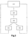
- Figure 3 illustrates a flowchart of the inventive control method for the exhaust gas aftertreatment system according to the present invention.
- a nominal amount of reductant agent may be injected into the exhaust gas mixture of the internal combustion engine upstream of the exhaust gas after treatment system 100, 200.
- the nominal amount of injected reductant agent may be taken from a first look-up table.
- Actual data (nominal amount of injected reductant agent) taken from the first look up table may be a function of a number of operating parameters such as catalyst temperature, engine speed, engine load, EGR level, NOx concentration upstream and downstream of said exhaust gas aftertreatment system.
- the actual data (nominal amount of injected reductant agent) taken from the first look-up table may be made by a control unit.
- Said control unit comprises an injection reductant agent model compiled from empirical data for the particular exhaust gas after treatment system 100, 200.
- a second look up table there is stored values for expected NOx conversion levels for each situation which may be determined by the nominal amount of injected reductant agent and at least one of the following parameters: catalyst temperature, engine speed, engine load, EGR level.
- a first step in the open loop experiment is to make two reduction agent injections.
- a first injection may be of nominal amount of injected reductant agent.
- a second injection may be an increase of the reductant agent injection by ⁇ compared to the amount of the first reductant agent injection.
- the measured NOx conversion level is increased by increasing the reductant injection amount by ⁇ in the second injection of reductant agent compared to the first injection of reductant injection implies that the assumption in the beginning of the experiment was correct, i.e. that the reductant buffer was in fact empty or almost empty. This case corresponds to a positive flank of curve 400 in figure 4 , i.e., to the left of a peak 402 in figure 4 .
- the open loop experiment continues to the filling step denoted by 340.
- the filling step at least one further reductant injection is controlled.
- said controlling of said at least one further injection of reductant is performed by continuing over-injection by said ⁇ in said open-loop experiment until a predetermined level of NOx conversion is reached. This may take one or a plurality of injections until it is fulfilled.
- said controlling of at least one further injection of reductant is performed by using an over injection which is higher than said ⁇ in said open-loop experiment until a predetermined level of NOx conversion is reached. This may take one or a plurality of injections until it is fulfilled.
- said controlling of at least one further injection of reductant is performed by using an over injection which is started by an over injection of ⁇ and then increased linearly, exponentially, for every successive injection until a predetermined level of NOx conversion is reached. This may take one or a plurality of injections until it is fulfilled.
- said controlling of at least one further injection of reductant is performed by using an over injection of a value equal to ⁇ or greater or smaller than said ⁇ which is continued a predetermined period of time. During said predetermined period of time one or a plurality of injections may be performed.
- said controlling of at least one further injection of reductant is performed by using an over injection of a value equal to ⁇ or greater or smaller than said ⁇ which is continued for a predetermined number of injections.
- Said number of injections may be one injection or a plurality of injections.
- the ⁇ values may be taken from the first look up table.
- Said ⁇ may be an increase of 1-25% of the nominal reductant injection amount.
- the NOx conversion level is decreased by increasing the second reductant agent injection amount by ⁇ from the first reductant agent injection amount, it implies that the assumption in the beginning of the experiment was incorrect, i.e. the reductant buffer was in fact full. This case corresponds to a negative flank of curve 400 in figure 4 , i.e., to the right of the peak 402 in figure 4 .
- At least one further reductant agent injection is controlled.
- said controlling of said at least one further injection of reductant agent is performed by an under-injection by ⁇ in said open-loop experiment until a predetermined level of NOx conversion is reached. This may take one or a plurality of injections until it is fulfilled.
- said controlling of at least one further injection of reductant is performed by using an under injection which is bigger than said ⁇ in said open-loop experiment until a predetermined level of NOx conversion is reached. This may take one or a plurality of injections until it is fulfilled.
- said controlling of at least one further injection of reductant agent is performed by using an under injection which is started by an under injection of ⁇ and then decreased linearly or exponentially for every successive injection until a predetermined level of NOx conversion is reached. This may take one or a plurality of injections until it is fulfilled.
- said controlling of at least one further injection of reductant is performed by using an under injection of a value equal to ⁇ or greater or smaller than said ⁇ which is continued a predetermined period of time. During said predetermined period of time one or a plurality of injections may be performed.
- said controlling of at least one further injection of reductant is performed by using an under injection of a value equal to ⁇ or greater or smaller than said ⁇ which is continued for a predetermined number of injections.
- Said number of injections may be one injection or a plurality of injections.
- the initial assumption when the open loop experiment is started is that the detected deviation between the measured NOx conversion and the expected NOx conversion according to the second look up table is caused by an empty reductant buffer.
- an assumption may be made that a reductant buffer is full instead of empty. If assuming that the buffer is full instead of empty, all of the above is still valid except that when the reductant agent injection amount is increased in the open loop experiment and the NOx conversion is increased said assumption is wrong, i.e., the buffer is empty and when the NOx conversion is decreased when increasing said reductant injection said assumption of an overfull buffer was correct and the injection amount should instead be reduced by an appropriate predetermined value.
- An assumption that the buffer is empty may normally result in choosing an over injection in order to fill up the buffer.
- An assumption that the buffer is full may normally result in choosing an under injection in order to empty the buffer.
- the assumption may be incorrect from the beginning, the assumed full buffer may in fact appear to be empty and the assumed empty buffer may in fact appear to be full. All this will be evident from the evaluation of the NOx conversion results of the reduction agent injections in the open loop experiment.
- the reductant injections (which may be denoted a first (nominal) and a second (increased/decreased with ⁇ ) performed in the open loop experiment before the evaluation step may be specific injections coupled to said experiment, i.e. additional injection sequence compared to a normal injection sequence which is given by the first look up table, i.e., different injection timing and different amount.
- said injections (which may be denoted a first (nominal) and a second (increased/decreased with ⁇ )) is embedded in the normal injection sequence.
- the first injection amount may be the reductant injection amount present when the open loop experiment is started.
- the first (nominal) reductant agent injection amount is determined from the model in the control unit and the circumstances given at that particular moment (catalyst temperature, engine speed, engine load, EGR level, NOx concentration upstream and downstream of said exhaust gas aftertreatment system).
- the second reductant agent injection amount may be said first injection amount plus a predetermined ⁇ amount.
- said second reductant agent injection amount is the value given by the model at said particular moment when said second injection is about to be performed. This means that the second reductant agent injection amount is determined from the model in the control unit and the circumstances given at that particular time (catalyst temperature, engine speed, engine load, EGR level, NOx concentration upstream and downstream of said exhaust gas aftertreatment system).
- the first and second injections are separated in time given by said injection model stored in said control unit.
- said second reductant agent injection may be increased/decreased by an amount ⁇ .
- the open loop experiment is continuing with increased or decreased injection amount (depending on the actual situation of the buffer level) until the NOx conversion level is equal to a predetermined value or when a predetermined number of injections have been performed of when a predetermined period of time has lapsed.
- the injection model is made out of measurement of a new catalyst.
- This injection model which may be performed when there is a detected deviation of expected NOx conversion and actual measured NOx conversion, aging of the catalyst is effectively taken care of. Storage capacity and NOx conversion may change as the catalyst becomes older and therefore the injection model which may be fully functional for a new catalyst may not be as good for an old catalyst.
- the result from evaluating the NOx conversion, from said first and second reductant injections, downstream said exhaust gas aftertreatment device to obtain a first and second result may be an indication or an estimation of the age of the catalyst. The more the measured NOx conversion result deviates from the estimated NOx conversion stored in said second look up table the older said catalyst may be.
- the result from evaluating the NOx conversion, from said first and second reductant injections, downstream said exhaust gas aftertreatment device to obtain a first and second result may be used to adjust the nominal injections given by the injection amount in said first look up table.
- the result from the open loop experiment may be used for adaptive adjustment of the nominal injections of reductant injections in the closed loop experiment.
- the open loop experiment for determining the buffer level of the catalyst or the age of the same may be used in combination with any standard closed loop control of the nominal injection of reductant agent.
- Figure 4 illustrates the NOx conversion degree as a function of stored/buffered amount of reductant agent.
- the NOx conversion is given in percentage implying that 100% equals full NOx conversion and 0% equal to no NOx conversion at all.
- Good NOx conversion is normally obtained when the stored amount of NH3 is about 20%-80% of maximum storage capacity.
- Good NOx conversion can be said to mean when the NOx conversion is higher than 50%.
- the amount of reductant is given in for instance in grams or cl. Even a low amount of stored reductant agent is sufficient to improve the NOx conversion. A reason why the NOx conversion decreases above max amount of stored reductant agent is that some of the superfluous reductant may be converted to NOx in the exhaust gas aftertreatment system.
- a computer program may comprise program code means for performing at least the open loop experiment when said program is run on a computer.
- a computer program product may comprise program code means stored on a computer readable medium for performing at least he open loop experiment when said program product is run on a computer.
Description
- The invention relates to a method for controlling a reductant buffer level in an exhaust gas aftertreatment device according to the preamble of the independent claim.
- Present regulatory conditions in the automotive market have led to an increasing demand to improve fuel economy and reduce emissions in present vehicles. These regulatory conditions must be balanced with the demands of a consumer for high performance and quick response for a vehicle.
- A diesel engine has an efficiency of up to about 52% and is thus the best converter of fossil energy. NOx emission concentration is dependent upon local oxygen atom concentration and the local temperature. Said high efficiency is however only possible at an elevated combustion temperature at which high NOx levels are inevitable. Moreover, a suppression of NOx formation by internal means (air/fuel ratio) has the tendency to cause an increase in particulates, known as the NOx-particulates trade off. Furthermore, an excess of oxygen in the exhaust gas from a diesel engine prevents the use of stoichiometric 3-way-catalyst technology for reduction of NOx as is used in gasoline engine cars from the late 80-ties. Reducing the oxides of nitrogen (NOx) and particulate matter (PM) in exhaust gases from a diesel engine has become a very important problem in view of the protection of environment and the saving of finite fossil energy supply.
- Vehicles equipped with diesel or other lean burn engines offer the benefit of increased fuel economy, however, catalytic reduction of NOx emissions via conventional means in such systems is difficult due to the high content of oxygen in the exhaust gas. In this regard Selective Catalytic Reduction (SCR) catalysts, in which NOx is continuously removed through active injection of a reductant into the exhaust gas mixture entering the catalyst are known to achieve high NOx conversion efficiency. Urea based SCR catalysts use gaseous ammonia as the active NOx reducing agent. Typically, an aqueous solution of urea is carried on board of a vehicle, and an injection system is used to supply it into the exhaust gas stream entering the SCR catalyst where it decomposes into hydro cyanic acid (NHCO) and gaseous ammonia (NH3), which is then used to convert NOx. However, in such systems, urea injection levels have to be very precisely controlled. Under-injection of urea may result in sub-optimal NOx conversion, while over-injection may cause tailpipe ammonia slip. In a typical urea-based SCR catalyst system, the amount of urea injected is in proportion to the exhaust gas NOx concentration that represents a trade-off between maximum NOX conversion and minimum ammonia slip.
-
WO2008/043928 discloses a method for controlling the amount of urea injected in a nitrogen oxide processing system with an SCR of the type mentioned above. The method is based on injecting various amounts of urea into the system and measuring and comparing the amounts of nitrogen oxides and ammonia at the outlet of the SCR for each urea amount that has been injected. - NOx conversion efficiency of an SCR catalyst is improved in the presence of adsorbed ammonia. However, it is not necessary that all of the catalyst storage capacity is utilized by ammonia in order to achieve optimal NOx conversion efficiency. On the other hand if too much ammonia is stored in the catalyst under certain operating conditions, such as high temperatures, some of the adsorbed ammonia in the catalyst may desorb and slip from the catalyst or to be oxidized to NOx and thereby reducing the overall NOx conversion efficiency.
- The problem with a reductant storage catalyst is the control of the amount of reductant stored in said catalyst since a direct measurement is not possible.
- It is an object of the invention to provide an improved method for controlling a reductant buffer level in an exhaust gas aftertreatment device which keeps the system out NOx levels at a low level.
- The objects are achieved by the features of the independent claims. The other claims and the description disclose advantageous embodiments of the invention.
- In a first aspect of the invention it is provided a method for controlling a reductant buffer level in an exhaust gas aftertreatment device connectable downstream of an internal combustion engine. Said method comprising the steps of: performing a first reductant injection of a first amount upstream said exhaust gas aftertreatment device, performing a second reductant injection of a second amount upstream said exhaust gas aftertreatment device, which second amount is different to said first amount. Said method further comprising the steps of: evaluating the NOx conversion resulting from said first and second reductant injections downstream said exhaust gas aftertreatment device to obtain a first and second result, controlling a further reductant injection in dependence of the first and second results from said first and second NOx conversion evaluations.
- An advantage of the present example embodiment of the invention is that the evaluation step and the control step, forming an open loop experiment, can be added to any present control method for the buffer level in the exhaust gas after treatment system.
- Another advantage of the present example embodiment of the invention is that the NOx conversion may be kept at a maximum while the open loop experiment is taking place.
- In another example embodiment of the present invention a further injection amount after said evaluating step may be increased or decreased compared to said first injection if said second result from said second NOx conversion evaluation is higher or lower than said first result from said first NOx conversion evaluation given that the second injection amount was higher than the first injection amount.
- In still another example embodiment of the present invention said further injection after said evaluating step may be decreased or increased compared to said first injection if said second result from said second NOx conversion evaluation is higher or lower than said first results from said first NOx conversion evaluation given that the second injection amount was lower than the first injection amount.
- An advantage of these embodiment s are that small alterations of the injected reductant immediately result in a change of NOx reductant level which in turn gives an indication of a empty or full exhaust gas after treatment reductant buffer.
- In still another example embodiment of the present invention said method further comprising the step of continuing said increased or decreased further injection until a predetermined level of NOx conversion is reached.
- An advantage of this embodiment is that an existing buffer management method may be improved by additional method steps which are independent of said existing buffer management method.
- Another advantage of this embodiment is that the buffer level can be kept at an optimal level irrespective of the starting conditions.
- Still another advantage of the present invention is that the open loop experiment may be initiated as often as one may require.
- The present invention together with the above-mentioned and other objects and advantages may best be understood from the following detailed description of the embodiment(s), but not restricted to the embodiments, wherein is shown schematically:
-
Fig. 1 and 2 illustrates a prior art exhaust gas aftertreatment system. -
Fig. 3 shows a flowchart of the inventive control method for the exhaust gas aftertreatment system. -
Fig. 4 depicts the NOx conversion degree as a function of stored amount of reductant agent. - In the drawings, equal or similar elements are referred to by equal reference numerals. The drawings are merely schematic representations, not intended to portray specific parameters of the invention. Moreover, the drawings are intended to depict only typical embodiments of the invention and therefore should not be considered as limiting the scope of the invention.
-
Fig. 1 depicts schematically a prior art exhaustgas aftertreatment system 100. Said exhaustgas aftertreatment system 100 comprises afirst NOx sensor 102, asecond NOx sensor 104, anSCR catalyst 106. Thefirst NOx sensor 102 is provided upstream saidSCR catalyst 106. Thesecond NOx sensor 104 is provided downstream saidSCR catalyst 106. Said SCRcatalyst 106 is provided with aninlet 110 and anoutlet 112. The reductant agent may be provided in theinlet 110 to saidSCR catalyst 106 or directly into saidSCR catalyst 106 before theoutlet 112. The reductant agent may be in the form of ammonia or urea. - The functionality of the SCR catalyst is well known in the art and need no further clarification in this context.
-
Fig. 2 depicts schematically another example of a prior art exhaustgas aftertreatment system 200. Said exhaustgas aftertreatment system 200 comprises afirst NOx sensor 202, asecond NOx sensor 204, aSCR catalyst 206 and aclean up catalyst 208. Thefirst NOx sensor 202 is provided upstream saidSCR catalyst 206. Thesecond NOx sensor 204 is provided downstream said clean upcatalyst 208. Said SCRcatalyst 206 is provided upstream of said clean upcatalyst 208. The exhaustgas aftertreatment system 200 is provided with aninlet 210 and anoutlet 212. The reductant agent may be provided in theinlet 210 to saidSCR catalyst 206 or directly into saidSCR catalyst 206 before the clean upcatalyst 208. The reductant agent may be in the form of ammonia or urea. The clean upcatalyst 208 may be used to neutralize any excess ammonia (ammonia slip). The clean-upcatalyst 208 may oxidize unused reductants and unadsorbed NH3 using stored oxygen or residual oxygen remaining in the exhaust according to the formula:
4NH3 + 302 => 2N2 + 6H2O.
4NH3 + 5O2 => 4NO + 6H2O
-
Figure 3 illustrates a flowchart of the inventive control method for the exhaust gas aftertreatment system according to the present invention. In normal operation 310 a nominal amount of reductant agent may be injected into the exhaust gas mixture of the internal combustion engine upstream of the exhaust gas aftertreatment system - Said control unit comprises an injection reductant agent model compiled from empirical data for the particular exhaust gas after
treatment system - In a second look up table there is stored values for expected NOx conversion levels for each situation which may be determined by the nominal amount of injected reductant agent and at least one of the following parameters: catalyst temperature, engine speed, engine load, EGR level.
- In case there is a deviation between the expected NOx conversion level and an actual measured NOx conversion level the method goes from the normal operation denoted by 310 to a reductant injection open loop experiment denoted by 320.
- In a first example embodiment of the
open loop experiment 320 an assumption is made that a reductant buffer is empty or almost empty in said exhaustgas aftertreatment system - Having made the assumption that the reductant buffer in the exhaust gas after
treatment system - In a next step of the open loop experiment an experiment result evaluation denoted by 330 is performed.
- If the measured NOx conversion level is increased by increasing the reductant injection amount by Δ in the second injection of reductant agent compared to the first injection of reductant injection implies that the assumption in the beginning of the experiment was correct, i.e. that the reductant buffer was in fact empty or almost empty. This case corresponds to a positive flank of
curve 400 infigure 4 , i.e., to the left of a peak 402 infigure 4 . - If the assumption is correct the open loop experiment continues to the filling step denoted by 340. In the filling step at least one further reductant injection is controlled.
- In a first example embodiment said controlling of said at least one further injection of reductant is performed by continuing over-injection by said Δ in said open-loop experiment until a predetermined level of NOx conversion is reached. This may take one or a plurality of injections until it is fulfilled.
- In another example embodiment said controlling of at least one further injection of reductant is performed by using an over injection which is higher than said Δ in said open-loop experiment until a predetermined level of NOx conversion is reached. This may take one or a plurality of injections until it is fulfilled.
- In still another example embodiment said controlling of at least one further injection of reductant is performed by using an over injection which is started by an over injection of Δ and then increased linearly, exponentially, for every successive injection until a predetermined level of NOx conversion is reached. This may take one or a plurality of injections until it is fulfilled.
- In still another example embodiment said controlling of at least one further injection of reductant is performed by using an over injection of a value equal to Δ or greater or smaller than said Δ which is continued a predetermined period of time. During said predetermined period of time one or a plurality of injections may be performed.
- In still another example embodiment said controlling of at least one further injection of reductant is performed by using an over injection of a value equal to Δ or greater or smaller than said Δ which is continued for a predetermined number of injections. Said number of injections may be one injection or a plurality of injections.
- The Δ values may be taken from the first look up table.
- Said Δ may be an increase of 1-25% of the nominal reductant injection amount.
- When the predetermined level of NOx conversion is reached or the predetermined time has lapsed or said predetermined number of injections has been made, the open loop experiment is finished and goes back to
normal operation 310 denoted by the arrow between the fillingbox 340 and thenormal operation 310. - If, in the experiment
result evaluation step 330, the NOx conversion level is decreased by increasing the second reductant agent injection amount by Δ from the first reductant agent injection amount, it implies that the assumption in the beginning of the experiment was incorrect, i.e. the reductant buffer was in fact full. This case corresponds to a negative flank ofcurve 400 infigure 4 , i.e., to the right of the peak 402 infigure 4 . - In the case that the first assumption was found to be incorrect a new assumption may be made that the reductant buffer is full and the open loop experiment continues to the emptying step denoted by 350.
- In the emptying
step 350 at least one further reductant agent injection is controlled. - In a first example embodiment said controlling of said at least one further injection of reductant agent is performed by an under-injection by Δ in said open-loop experiment until a predetermined level of NOx conversion is reached. This may take one or a plurality of injections until it is fulfilled.
- In another example embodiment said controlling of at least one further injection of reductant is performed by using an under injection which is bigger than said Δ in said open-loop experiment until a predetermined level of NOx conversion is reached. This may take one or a plurality of injections until it is fulfilled.
- In still another example embodiment said controlling of at least one further injection of reductant agent is performed by using an under injection which is started by an under injection of Δ and then decreased linearly or exponentially for every successive injection until a predetermined level of NOx conversion is reached. This may take one or a plurality of injections until it is fulfilled.
- In still another example embodiment said controlling of at least one further injection of reductant is performed by using an under injection of a value equal to Δ or greater or smaller than said Δ which is continued a predetermined period of time. During said predetermined period of time one or a plurality of injections may be performed.
- In still another example embodiment said controlling of at least one further injection of reductant is performed by using an under injection of a value equal to Δ or greater or smaller than said Δ which is continued for a predetermined number of injections. Said number of injections may be one injection or a plurality of injections.
- When the predetermined level of NOx conversion is reached the open loop experiment is finished and goes back to
normal operation 310 denoted by the arrow between theemptying box 350 and thenormal operation box 310. - In the example embodiment above the initial assumption when the open loop experiment is started is that the detected deviation between the measured NOx conversion and the expected NOx conversion according to the second look up table is caused by an empty reductant buffer. However, in a second example embodiment of the open loop experiment an assumption may be made that a reductant buffer is full instead of empty. If assuming that the buffer is full instead of empty, all of the above is still valid except that when the reductant agent injection amount is increased in the open loop experiment and the NOx conversion is increased said assumption is wrong, i.e., the buffer is empty and when the NOx conversion is decreased when increasing said reductant injection said assumption of an overfull buffer was correct and the injection amount should instead be reduced by an appropriate predetermined value.
- If on the other hand one is starting with the assumption that the buffer is full and a decreased injection amount of reductant agent with Δ will result in an increased NOx conversion implies that the assumption of a full buffer was correct. However, if starting with the assumption that the buffer is full and decreasing the injection amount with Δ resulting in a decreased NOx conversion implies that the assumption was incorrect, i.e. the buffer was empty.
- An assumption that the buffer is empty may normally result in choosing an over injection in order to fill up the buffer. An assumption that the buffer is full may normally result in choosing an under injection in order to empty the buffer. However, the assumption may be incorrect from the beginning, the assumed full buffer may in fact appear to be empty and the assumed empty buffer may in fact appear to be full. All this will be evident from the evaluation of the NOx conversion results of the reduction agent injections in the open loop experiment.
- In another example embodiment the reductant injections (which may be denoted a first (nominal) and a second (increased/decreased with Δ) performed in the open loop experiment before the evaluation step may be specific injections coupled to said experiment, i.e. additional injection sequence compared to a normal injection sequence which is given by the first look up table, i.e., different injection timing and different amount.
- In the example embodiment described in detail above said injections, (which may be denoted a first (nominal) and a second (increased/decreased with Δ)) is embedded in the normal injection sequence. The first injection amount may be the reductant injection amount present when the open loop experiment is started. The first (nominal) reductant agent injection amount is determined from the model in the control unit and the circumstances given at that particular moment (catalyst temperature, engine speed, engine load, EGR level, NOx concentration upstream and downstream of said exhaust gas aftertreatment system).
- The second reductant agent injection amount may be said first injection amount plus a predetermined Δ amount. In another example embodiment said second reductant agent injection amount is the value given by the model at said particular moment when said second injection is about to be performed. This means that the second reductant agent injection amount is determined from the model in the control unit and the circumstances given at that particular time (catalyst temperature, engine speed, engine load, EGR level, NOx concentration upstream and downstream of said exhaust gas aftertreatment system). The first and second injections are separated in time given by said injection model stored in said control unit. In said open loop experiment said second reductant agent injection may be increased/decreased by an amount Δ.
- The open loop experiment is continuing with increased or decreased injection amount (depending on the actual situation of the buffer level) until the NOx conversion level is equal to a predetermined value or when a predetermined number of injections have been performed of when a predetermined period of time has lapsed.
- The injection model is made out of measurement of a new catalyst. When adding the open loop experiment to this injection model, which may be performed when there is a detected deviation of expected NOx conversion and actual measured NOx conversion, aging of the catalyst is effectively taken care of. Storage capacity and NOx conversion may change as the catalyst becomes older and therefore the injection model which may be fully functional for a new catalyst may not be as good for an old catalyst. Instead of having different injection models depending on the age of the catalyst, one may use one single injection model and the open loop experiment. This combination of a single injection model with the open loop experiment will achieve good NOx conversion through out the life time of the catalyst at the same time as there is a low urea slip.
- The result from evaluating the NOx conversion, from said first and second reductant injections, downstream said exhaust gas aftertreatment device to obtain a first and second result may be an indication or an estimation of the age of the catalyst. The more the measured NOx conversion result deviates from the estimated NOx conversion stored in said second look up table the older said catalyst may be.
- The result from evaluating the NOx conversion, from said first and second reductant injections, downstream said exhaust gas aftertreatment device to obtain a first and second result may be used to adjust the nominal injections given by the injection amount in said first look up table. This means that the result from the open loop experiment may be used for adaptive adjustment of the nominal injections of reductant injections in the closed loop experiment.
- The open loop experiment for determining the buffer level of the catalyst or the age of the same may be used in combination with any standard closed loop control of the nominal injection of reductant agent.
-
Figure 4 illustrates the NOx conversion degree as a function of stored/buffered amount of reductant agent. The NOx conversion is given in percentage implying that 100% equals full NOx conversion and 0% equal to no NOx conversion at all. Good NOx conversion is normally obtained when the stored amount of NH3 is about 20%-80% of maximum storage capacity. Good NOx conversion can be said to mean when the NOx conversion is higher than 50%. - The amount of reductant is given in for instance in grams or cl. Even a low amount of stored reductant agent is sufficient to improve the NOx conversion. A reason why the NOx conversion decreases above max amount of stored reductant agent is that some of the superfluous reductant may be converted to NOx in the exhaust gas aftertreatment system.
- A computer program may comprise program code means for performing at least the open loop experiment when said program is run on a computer.
- A computer program product may comprise program code means stored on a computer readable medium for performing at least he open loop experiment when said program product is run on a computer.
- The invention should not be deemed to be limited to the embodiments described above, but rather a number of further variants and modifications are conceivable within the scope of the following patent claims.
Claims (19)
- A method for controlling a fill level of a reductant buffer level in an exhaust gas aftertreatment device (100, 200) connectable downstream of an internal combustion engine, said method comprising the steps of.a. making an assumption of the fill level of the reductant buffer, the assumption being that the reductant buffer is empty or almost empty or that the reductant buffer is full,b. performing a first reductant injection of a first amount upstream said exhaust gas aftertreatment device,c. evaluating the NOx conversion (330), resulting from said first reductant injection, downstream said exhaust gas aftertreatment device to obtain a first result,d. performing a second reductant injection of a second amount upstream said exhaust gas aftertreatment device, which second amount is different to said first amount,e. evaluating the NOx conversion (330), resulting from said second reductant injection, downstream said exhaust gas aftertreatment device to obtain a second result,f. determining whether the assumption of the fill level of the reductant buffer is correct in dependence of the first and second results from said first and second NOx conversion evaluations,g. controlling at least one further reductant injection (340, 350) based on whether the assumption of the fill level of the reductant buffer was correct or not.
- The method according to claim 1, wherein said first injection amount is smaller than said second injection amount.
- The method according to claim 2, wherein a further injection amount after said evaluating step (330) is increased compared to said first injection or to a nominal injection if said second result from said second NOx conversion evaluation is higher than said first result from said first NOx conversion evaluation.
- The method according to claim 2, wherein a further injection amount after said evaluating step (330) is decreased compared to said first injection or to a nominal injection if said second result from said second NOx conversion evaluation is essentially identical or lower than said first result from said first NOx conversion evaluation.
- The method according to claim 1, wherein said first reductant injection is equal to the nominal injection according to the injection model.
- The method according to claim 1, wherein said evaluation of the NOx conversion comprising the steps of:- measuring said NOx content of the exhaust gases with a first NOx sensor (102, 202) provided upstream said exhaust gas aftertreatment device,- measuring said NOx content of the exhaust gases with a second NOx sensor (104, 204) provided downstream said exhaust gas aftertreatment device,- comparing the measurement of from said first and second NOx sensors 102, 202, 104, 204).
- The method according to claim 1, further comprising the step of injecting said reductant agent directly into the exhaust gas aftertreatment device (100, 200).
- The method according to claim 1, wherein said reductant agent is urea.
- The method according to claim 3 or 4, further comprising the step of:- continuing said increased or decreased further injection (340, 350) of reductant agent until at least one of the following parameters is fulfilled: a predetermined level of NOx conversion is reached, a predetermined number of injections is performed or a predetermined period of time has lapsed.
- The method according to claim 1, further comprising the steps of:- comparing a detected NOx conversion level and an estimated NOx conversion level,- initiating step b) in claim 1 if there is a deviation between said detected NOx conversion and said estimated NOx conversion.
- The method according to claim 1, wherein said first injection amount is greater than said second injection amount.
- The method according to claim 11, wherein said further injection after said evaluating step (330) is decreased compared to said first injection or a nominal injection if said second result from said second NOx conversion evaluation is higher than said first results from said first NOx conversion evaluation.
- The method according to claim 11, wherein said further injection after said evaluating step (330) is increased compared to said first injection or a nominal injection if said second result from said second NOx conversion evaluation is essentially identical or lower than said first results from said first NOx conversion evaluation.
- The method according to claim 12 or 13, further comprising the step of:- continuing said increased or decreased further injection until at least one of the following parameters is fulfilled: a predetermined level of NOx conversion is reached, a predetermined number of injections is performed or a predetermined period of time has lapsed.
- The method according to claim 1, further comprising the step of:- estimating the age of said exhaust gas after treatment device in dependence of the first and second results from said first and second NOx conversion evaluations.
- The method according to claim 5, further comprising the step of:- adjusting the nominal injection of reductant agent in a closed loop in dependence of the first and second results from said first and second NOx conversion evaluations (330).
- The method according to claim 1, further comprising the step of:- combining step a-g with a closed loop control of nominal injections of reductant agent.
- A computer program comprising program code means for performing all the steps of any one of the claims 1-17 when said program is run on a computer.
- A computer program product comprising program code means stored on a computer readable medium for performing all steps of anyone of the claims 1-17 when said program product is run on a computer.
Applications Claiming Priority (1)
| Application Number | Priority Date | Filing Date | Title |
|---|---|---|---|
| PCT/SE2009/000530 WO2011075015A1 (en) | 2009-12-18 | 2009-12-18 | Method for controlling the reductant buffer level in an exhaust gas aftertreatment device |
Publications (3)
| Publication Number | Publication Date |
|---|---|
| EP2513439A1 EP2513439A1 (en) | 2012-10-24 |
| EP2513439A4 EP2513439A4 (en) | 2016-06-15 |
| EP2513439B1 true EP2513439B1 (en) | 2018-05-02 |
Family
ID=44167538
Family Applications (1)
| Application Number | Title | Priority Date | Filing Date |
|---|---|---|---|
| EP09852353.3A Active EP2513439B1 (en) | 2009-12-18 | 2009-12-18 | Method for controlling the reductant buffer level in an exhaust gas aftertreatment device |
Country Status (7)
| Country | Link |
|---|---|
| US (2) | US9243535B2 (en) |
| EP (1) | EP2513439B1 (en) |
| JP (1) | JP5759476B2 (en) |
| CN (1) | CN102713180B (en) |
| BR (1) | BR112012014614B1 (en) |
| RU (1) | RU2532463C2 (en) |
| WO (1) | WO2011075015A1 (en) |
Families Citing this family (10)
| Publication number | Priority date | Publication date | Assignee | Title |
|---|---|---|---|---|
| DE102012201749B4 (en) * | 2012-02-07 | 2024-02-15 | Robert Bosch Gmbh | Method for monitoring an SCR catalytic converter |
| US20140123629A1 (en) * | 2012-11-02 | 2014-05-08 | International Engine Intellectual Property Company, Llc | Ammonia slip detection |
| US8935915B2 (en) * | 2012-11-05 | 2015-01-20 | International Engine Intellectual Property Company, Llc. | Ammonia storage on an SCR catalyst |
| DE102012025002A1 (en) | 2012-12-20 | 2014-06-26 | Volkswagen Aktiengesellschaft | Method for diagnosing a catalytic converter, diagnostic device and motor vehicle with such |
| US9903247B2 (en) * | 2015-12-31 | 2018-02-27 | Cummins Emission Solutions Inc. | Reductant apportionment for multi-dosing architectures |
| DE102018203757A1 (en) * | 2017-04-25 | 2018-10-25 | Robert Bosch Gmbh | Method for operating an SCR system with at least two metering valves |
| GB201818633D0 (en) * | 2018-11-15 | 2019-01-02 | Agco Int Gmbh | Nox slip detection |
| US11035273B2 (en) * | 2019-01-31 | 2021-06-15 | Hyundai Motor Company | After treatment system and after treatment method for lean-burn engine |
| DE102019207757B4 (en) * | 2019-05-27 | 2021-10-14 | Vitesco Technologies GmbH | Method for operating an exhaust gas aftertreatment system of an internal combustion engine and an exhaust gas aftertreatment system |
| CN112360600A (en) * | 2020-10-30 | 2021-02-12 | 凯龙高科技股份有限公司 | SCR injection control system for internal combustion engine test bench based on air inflow |
Family Cites Families (27)
| Publication number | Priority date | Publication date | Assignee | Title |
|---|---|---|---|---|
| DE10100420A1 (en) * | 2001-01-08 | 2002-07-11 | Bosch Gmbh Robert | Method and device for controlling an exhaust gas aftertreatment system |
| US7093427B2 (en) | 2002-11-21 | 2006-08-22 | Ford Global Technologies, Llc | Exhaust gas aftertreatment systems |
| CN100355488C (en) * | 2003-05-07 | 2007-12-19 | 韩国高化环保技术有限公司 | Catalytic process for nitrogen oxides reduction by multi-injection and use thereof |
| CN100529340C (en) | 2004-06-08 | 2009-08-19 | 卡明斯公司 | Method for modifying trigger level for adsorber regeneration |
| US20050282285A1 (en) * | 2004-06-21 | 2005-12-22 | Eaton Corporation | Strategy for controlling NOx emissions and ammonia slip in an SCR system using a nonselective NOx/NH3 |
| JP4267534B2 (en) * | 2004-07-23 | 2009-05-27 | 日野自動車株式会社 | Abnormality detection method for exhaust purification system |
| DE102004046640B4 (en) * | 2004-09-25 | 2013-07-11 | Robert Bosch Gmbh | Method for operating an internal combustion engine and device for carrying out the method |
| DE102005012568A1 (en) * | 2005-03-18 | 2006-09-21 | Daimlerchrysler Ag | Device for removing nitrogen oxides from engine exhaust gas and method for metering an additive for engine exhaust gas |
| RU2007147908A (en) * | 2005-06-03 | 2009-09-10 | Эмитек Гезельшафт фюр Эмиссионстехнологи мбХ (DE) | METHOD AND DEVICE FOR TREATMENT OF EXHAUST GASES FORMED WHEN WORKING INTERNAL COMBUSTION ENGINES |
| DE102005038571A1 (en) * | 2005-08-12 | 2007-02-15 | Emitec Gesellschaft Für Emissionstechnologie Mbh | Method and device for the selective catalytic reduction of nitrogen oxides in the exhaust gas of an internal combustion engine |
| CN100587235C (en) * | 2005-09-29 | 2010-02-03 | 沃尔沃拉斯特瓦格纳公司 | Diagnosis method for exhaustion post-processing system |
| JP2008037770A (en) | 2006-08-02 | 2008-02-21 | Nippon Barrier Free:Kk | Anti-aging agent |
| FR2907160B1 (en) * | 2006-10-13 | 2008-12-26 | Peugeot Citroen Automobiles Sa | UREA QUANTITY CLOSED LOOP CONTROL METHOD FOR NITROGEN OXIDE PROCESSING SYSTEM |
| JP2008151039A (en) * | 2006-12-18 | 2008-07-03 | Mitsubishi Motors Corp | Exhaust emission control device |
| JP2008157136A (en) * | 2006-12-25 | 2008-07-10 | Mitsubishi Fuso Truck & Bus Corp | Exhaust emission control device for internal combustion engine |
| US7707824B2 (en) | 2007-04-10 | 2010-05-04 | Gm Global Technology Operations, Inc. | Excess NH3 storage control for SCR catalysts |
| US7886527B2 (en) * | 2007-04-10 | 2011-02-15 | Gm Global Technology Operations, Inc. | Reductant injection control strategy |
| US8171724B2 (en) * | 2007-05-02 | 2012-05-08 | Ford Global Technologies, Llc | Vehicle-based strategy for removing urea deposits from an SCR catalyst |
| KR100957138B1 (en) * | 2007-07-09 | 2010-05-11 | 현대자동차주식회사 | Method for determining malfunction of nitrogen oxide sensor and selective catalytic reduction system operating the same |
| DE102007044610B4 (en) * | 2007-09-19 | 2010-04-08 | Continental Automotive Gmbh | A method of detecting the minimum opening time of a reductant delivery device in an exhaust aftertreatment system with an SCR catalyst |
| JP4986839B2 (en) * | 2007-12-27 | 2012-07-25 | 日野自動車株式会社 | Exhaust treatment device |
| DE102008041603A1 (en) * | 2008-08-27 | 2010-03-04 | Robert Bosch Gmbh | Method for operating an internal combustion engine with SCR catalytic converter |
| US8893476B2 (en) * | 2008-12-12 | 2014-11-25 | Volvo Lastvagnar Ab | SCR closed loop control system |
| US9255510B2 (en) * | 2009-03-09 | 2016-02-09 | GM Global Technology Operations LLC | Ammonia (NH3) storage control system and method based on a nitrogen oxide(NOx) sensor |
| CN102844533B (en) * | 2010-01-01 | 2015-05-20 | 康明斯知识产权公司 | Engine and exhaust aftertreatment control |
| US8495862B2 (en) * | 2010-10-06 | 2013-07-30 | GM Global Technology Operations LLC | System and method for detecting low quality reductant and catalyst degradation in selective catalytic reduction systems |
| DE102011008380B3 (en) * | 2011-01-12 | 2012-01-26 | Continental Automotive Gmbh | Catalytic converter system and method for operating a catalytic converter |
-
2009
- 2009-12-18 WO PCT/SE2009/000530 patent/WO2011075015A1/en active Application Filing
- 2009-12-18 EP EP09852353.3A patent/EP2513439B1/en active Active
- 2009-12-18 RU RU2012130157/06A patent/RU2532463C2/en active
- 2009-12-18 JP JP2012544426A patent/JP5759476B2/en active Active
- 2009-12-18 US US13/516,246 patent/US9243535B2/en active Active
- 2009-12-18 CN CN200980163020.8A patent/CN102713180B/en active Active
- 2009-12-18 BR BR112012014614-9A patent/BR112012014614B1/en not_active IP Right Cessation
-
2015
- 2015-09-17 US US14/857,579 patent/US20160003121A1/en not_active Abandoned
Non-Patent Citations (1)
| Title |
|---|
| None * |
Also Published As
| Publication number | Publication date |
|---|---|
| RU2532463C2 (en) | 2014-11-10 |
| US20160003121A1 (en) | 2016-01-07 |
| CN102713180B (en) | 2015-09-16 |
| US20130186067A1 (en) | 2013-07-25 |
| JP2013514490A (en) | 2013-04-25 |
| JP5759476B2 (en) | 2015-08-05 |
| CN102713180A (en) | 2012-10-03 |
| EP2513439A1 (en) | 2012-10-24 |
| US9243535B2 (en) | 2016-01-26 |
| BR112012014614A8 (en) | 2016-05-17 |
| WO2011075015A1 (en) | 2011-06-23 |
| EP2513439A4 (en) | 2016-06-15 |
| BR112012014614A2 (en) | 2016-04-12 |
| BR112012014614B1 (en) | 2020-12-08 |
| RU2012130157A (en) | 2014-01-27 |
Similar Documents
| Publication | Publication Date | Title |
|---|---|---|
| EP2513439B1 (en) | Method for controlling the reductant buffer level in an exhaust gas aftertreatment device | |
| JP5880731B2 (en) | Exhaust gas purification device for internal combustion engine | |
| EP2126306B1 (en) | On-board-diagnosis method for an exhaust aftertreatment system and on-board-diagnosis system for an exhaust aftertreatment system | |
| US9038370B2 (en) | Method for operating an exhaust emission control system having a SCR-catalyst and an upstream oxidation catalyst exhaust emission control component | |
| EP2563500B1 (en) | Scr catalyst ammonia surface coverage estimation and control | |
| EP2060756B1 (en) | Method and system using a reduction catalyst to reduce nitrate oxide | |
| US8978367B2 (en) | Exhaust gas purifying system of internal combustion engine | |
| US8875497B2 (en) | Exhaust purification system for internal combustion engine | |
| US8726641B2 (en) | Method for controlling injection of diesel exhaust fluid into an exhaust pipe of an internal combustion engine | |
| JP6200088B2 (en) | Method for operating an exhaust gas purification system of an internal combustion engine | |
| US8893476B2 (en) | SCR closed loop control system | |
| WO2009135016A2 (en) | Apparatus, system, and method for reducing nox emissions on an scr catalyst | |
| WO2009135014A2 (en) | Apparatus, system, and method for reducing nox emissions on an scr catalyst using ammonia storage and slip control | |
| WO2009135010A2 (en) | Apparatus, system, and method for controlling ammonia slip from an scr catalyst | |
| WO2009135021A2 (en) | Apparatus, system, and method for reducing nox emissions on an scr catalyst | |
| US9051865B2 (en) | Method for controlling a system for the treatment of exhaust gases from an internal combustion engine | |
| JP2008157136A (en) | Exhaust emission control device for internal combustion engine | |
| JP5915516B2 (en) | Exhaust gas purification device for internal combustion engine | |
| US9482133B2 (en) | Exhaust emission control system of internal combustion engine | |
| CN110630358B (en) | Passive nitrogen oxide storage catalyst management | |
| US20120000183A1 (en) | Method for injecting ammonia into an exhaust gas stream | |
| JP2015135117A (en) | Method for controlling reductant agent storage level in exhaust gas post-treatment device | |
| JP5126141B2 (en) | Exhaust gas purification device for internal combustion engine | |
| CN115788635A (en) | Method for correcting SCR (Selective catalytic reduction) NH3 storage model |
Legal Events
| Date | Code | Title | Description |
|---|---|---|---|
| PUAI | Public reference made under article 153(3) epc to a published international application that has entered the european phase |
Free format text: ORIGINAL CODE: 0009012 |
|
| 17P | Request for examination filed |
Effective date: 20120718 |
|
| AK | Designated contracting states |
Kind code of ref document: A1 Designated state(s): AT BE BG CH CY CZ DE DK EE ES FI FR GB GR HR HU IE IS IT LI LT LU LV MC MK MT NL NO PL PT RO SE SI SK SM TR |
|
| DAX | Request for extension of the european patent (deleted) | ||
| RA4 | Supplementary search report drawn up and despatched (corrected) |
Effective date: 20160512 |
|
| RIC1 | Information provided on ipc code assigned before grant |
Ipc: F01N 3/20 20060101AFI20160506BHEP Ipc: F01N 11/00 20060101ALI20160506BHEP |
|
| 17Q | First examination report despatched |
Effective date: 20170329 |
|
| GRAP | Despatch of communication of intention to grant a patent |
Free format text: ORIGINAL CODE: EPIDOSNIGR1 |
|
| INTG | Intention to grant announced |
Effective date: 20171124 |
|
| GRAS | Grant fee paid |
Free format text: ORIGINAL CODE: EPIDOSNIGR3 |
|
| GRAA | (expected) grant |
Free format text: ORIGINAL CODE: 0009210 |
|
| RIN1 | Information on inventor provided before grant (corrected) |
Inventor name: DAHL, JOHAN Inventor name: KAELLEN, PER-OLOF |
|
| AK | Designated contracting states |
Kind code of ref document: B1 Designated state(s): AT BE BG CH CY CZ DE DK EE ES FI FR GB GR HR HU IE IS IT LI LT LU LV MC MK MT NL NO PL PT RO SE SI SK SM TR |
|
| REG | Reference to a national code |
Ref country code: GB Ref legal event code: FG4D |
|
| REG | Reference to a national code |
Ref country code: CH Ref legal event code: EP Ref country code: AT Ref legal event code: REF Ref document number: 995493 Country of ref document: AT Kind code of ref document: T Effective date: 20180515 |
|
| REG | Reference to a national code |
Ref country code: DE Ref legal event code: R096 Ref document number: 602009052174 Country of ref document: DE Ref country code: IE Ref legal event code: FG4D |
|
| REG | Reference to a national code |
Ref country code: SE Ref legal event code: TRGR |
|
| REG | Reference to a national code |
Ref country code: NL Ref legal event code: MP Effective date: 20180502 |
|
| REG | Reference to a national code |
Ref country code: LT Ref legal event code: MG4D |
|
| PG25 | Lapsed in a contracting state [announced via postgrant information from national office to epo] |
Ref country code: FI Free format text: LAPSE BECAUSE OF FAILURE TO SUBMIT A TRANSLATION OF THE DESCRIPTION OR TO PAY THE FEE WITHIN THE PRESCRIBED TIME-LIMIT Effective date: 20180502 Ref country code: BG Free format text: LAPSE BECAUSE OF FAILURE TO SUBMIT A TRANSLATION OF THE DESCRIPTION OR TO PAY THE FEE WITHIN THE PRESCRIBED TIME-LIMIT Effective date: 20180802 Ref country code: NO Free format text: LAPSE BECAUSE OF FAILURE TO SUBMIT A TRANSLATION OF THE DESCRIPTION OR TO PAY THE FEE WITHIN THE PRESCRIBED TIME-LIMIT Effective date: 20180802 Ref country code: LT Free format text: LAPSE BECAUSE OF FAILURE TO SUBMIT A TRANSLATION OF THE DESCRIPTION OR TO PAY THE FEE WITHIN THE PRESCRIBED TIME-LIMIT Effective date: 20180502 Ref country code: ES Free format text: LAPSE BECAUSE OF FAILURE TO SUBMIT A TRANSLATION OF THE DESCRIPTION OR TO PAY THE FEE WITHIN THE PRESCRIBED TIME-LIMIT Effective date: 20180502 |
|
| PG25 | Lapsed in a contracting state [announced via postgrant information from national office to epo] |
Ref country code: GR Free format text: LAPSE BECAUSE OF FAILURE TO SUBMIT A TRANSLATION OF THE DESCRIPTION OR TO PAY THE FEE WITHIN THE PRESCRIBED TIME-LIMIT Effective date: 20180803 Ref country code: NL Free format text: LAPSE BECAUSE OF FAILURE TO SUBMIT A TRANSLATION OF THE DESCRIPTION OR TO PAY THE FEE WITHIN THE PRESCRIBED TIME-LIMIT Effective date: 20180502 Ref country code: HR Free format text: LAPSE BECAUSE OF FAILURE TO SUBMIT A TRANSLATION OF THE DESCRIPTION OR TO PAY THE FEE WITHIN THE PRESCRIBED TIME-LIMIT Effective date: 20180502 Ref country code: LV Free format text: LAPSE BECAUSE OF FAILURE TO SUBMIT A TRANSLATION OF THE DESCRIPTION OR TO PAY THE FEE WITHIN THE PRESCRIBED TIME-LIMIT Effective date: 20180502 |
|
| REG | Reference to a national code |
Ref country code: AT Ref legal event code: MK05 Ref document number: 995493 Country of ref document: AT Kind code of ref document: T Effective date: 20180502 |
|
| PG25 | Lapsed in a contracting state [announced via postgrant information from national office to epo] |
Ref country code: PT Free format text: LAPSE BECAUSE OF FAILURE TO SUBMIT A TRANSLATION OF THE DESCRIPTION OR TO PAY THE FEE WITHIN THE PRESCRIBED TIME-LIMIT Effective date: 20180903 |
|
| PG25 | Lapsed in a contracting state [announced via postgrant information from national office to epo] |
Ref country code: AT Free format text: LAPSE BECAUSE OF FAILURE TO SUBMIT A TRANSLATION OF THE DESCRIPTION OR TO PAY THE FEE WITHIN THE PRESCRIBED TIME-LIMIT Effective date: 20180502 Ref country code: RO Free format text: LAPSE BECAUSE OF FAILURE TO SUBMIT A TRANSLATION OF THE DESCRIPTION OR TO PAY THE FEE WITHIN THE PRESCRIBED TIME-LIMIT Effective date: 20180502 Ref country code: CZ Free format text: LAPSE BECAUSE OF FAILURE TO SUBMIT A TRANSLATION OF THE DESCRIPTION OR TO PAY THE FEE WITHIN THE PRESCRIBED TIME-LIMIT Effective date: 20180502 Ref country code: EE Free format text: LAPSE BECAUSE OF FAILURE TO SUBMIT A TRANSLATION OF THE DESCRIPTION OR TO PAY THE FEE WITHIN THE PRESCRIBED TIME-LIMIT Effective date: 20180502 Ref country code: PL Free format text: LAPSE BECAUSE OF FAILURE TO SUBMIT A TRANSLATION OF THE DESCRIPTION OR TO PAY THE FEE WITHIN THE PRESCRIBED TIME-LIMIT Effective date: 20180502 Ref country code: DK Free format text: LAPSE BECAUSE OF FAILURE TO SUBMIT A TRANSLATION OF THE DESCRIPTION OR TO PAY THE FEE WITHIN THE PRESCRIBED TIME-LIMIT Effective date: 20180502 Ref country code: SK Free format text: LAPSE BECAUSE OF FAILURE TO SUBMIT A TRANSLATION OF THE DESCRIPTION OR TO PAY THE FEE WITHIN THE PRESCRIBED TIME-LIMIT Effective date: 20180502 |
|
| REG | Reference to a national code |
Ref country code: DE Ref legal event code: R097 Ref document number: 602009052174 Country of ref document: DE |
|
| PG25 | Lapsed in a contracting state [announced via postgrant information from national office to epo] |
Ref country code: IT Free format text: LAPSE BECAUSE OF FAILURE TO SUBMIT A TRANSLATION OF THE DESCRIPTION OR TO PAY THE FEE WITHIN THE PRESCRIBED TIME-LIMIT Effective date: 20180502 Ref country code: SM Free format text: LAPSE BECAUSE OF FAILURE TO SUBMIT A TRANSLATION OF THE DESCRIPTION OR TO PAY THE FEE WITHIN THE PRESCRIBED TIME-LIMIT Effective date: 20180502 |
|
| PLBE | No opposition filed within time limit |
Free format text: ORIGINAL CODE: 0009261 |
|
| STAA | Information on the status of an ep patent application or granted ep patent |
Free format text: STATUS: NO OPPOSITION FILED WITHIN TIME LIMIT |
|
| 26N | No opposition filed |
Effective date: 20190205 |
|
| PG25 | Lapsed in a contracting state [announced via postgrant information from national office to epo] |
Ref country code: SI Free format text: LAPSE BECAUSE OF FAILURE TO SUBMIT A TRANSLATION OF THE DESCRIPTION OR TO PAY THE FEE WITHIN THE PRESCRIBED TIME-LIMIT Effective date: 20180502 |
|
| REG | Reference to a national code |
Ref country code: CH Ref legal event code: PL |
|
| GBPC | Gb: european patent ceased through non-payment of renewal fee |
Effective date: 20181218 |
|
| PG25 | Lapsed in a contracting state [announced via postgrant information from national office to epo] |
Ref country code: MC Free format text: LAPSE BECAUSE OF FAILURE TO SUBMIT A TRANSLATION OF THE DESCRIPTION OR TO PAY THE FEE WITHIN THE PRESCRIBED TIME-LIMIT Effective date: 20180502 Ref country code: LU Free format text: LAPSE BECAUSE OF NON-PAYMENT OF DUE FEES Effective date: 20181218 |
|
| REG | Reference to a national code |
Ref country code: IE Ref legal event code: MM4A |
|
| REG | Reference to a national code |
Ref country code: BE Ref legal event code: MM Effective date: 20181231 |
|
| PG25 | Lapsed in a contracting state [announced via postgrant information from national office to epo] |
Ref country code: IE Free format text: LAPSE BECAUSE OF NON-PAYMENT OF DUE FEES Effective date: 20181218 |
|
| PG25 | Lapsed in a contracting state [announced via postgrant information from national office to epo] |
Ref country code: BE Free format text: LAPSE BECAUSE OF NON-PAYMENT OF DUE FEES Effective date: 20181231 |
|
| PG25 | Lapsed in a contracting state [announced via postgrant information from national office to epo] |
Ref country code: CH Free format text: LAPSE BECAUSE OF NON-PAYMENT OF DUE FEES Effective date: 20181231 Ref country code: LI Free format text: LAPSE BECAUSE OF NON-PAYMENT OF DUE FEES Effective date: 20181231 Ref country code: GB Free format text: LAPSE BECAUSE OF NON-PAYMENT OF DUE FEES Effective date: 20181218 |
|
| PG25 | Lapsed in a contracting state [announced via postgrant information from national office to epo] |
Ref country code: MT Free format text: LAPSE BECAUSE OF NON-PAYMENT OF DUE FEES Effective date: 20181218 |
|
| PG25 | Lapsed in a contracting state [announced via postgrant information from national office to epo] |
Ref country code: TR Free format text: LAPSE BECAUSE OF FAILURE TO SUBMIT A TRANSLATION OF THE DESCRIPTION OR TO PAY THE FEE WITHIN THE PRESCRIBED TIME-LIMIT Effective date: 20180502 |
|
| PG25 | Lapsed in a contracting state [announced via postgrant information from national office to epo] |
Ref country code: CY Free format text: LAPSE BECAUSE OF FAILURE TO SUBMIT A TRANSLATION OF THE DESCRIPTION OR TO PAY THE FEE WITHIN THE PRESCRIBED TIME-LIMIT Effective date: 20180502 Ref country code: MK Free format text: LAPSE BECAUSE OF NON-PAYMENT OF DUE FEES Effective date: 20180502 Ref country code: HU Free format text: LAPSE BECAUSE OF FAILURE TO SUBMIT A TRANSLATION OF THE DESCRIPTION OR TO PAY THE FEE WITHIN THE PRESCRIBED TIME-LIMIT; INVALID AB INITIO Effective date: 20091218 |
|
| PG25 | Lapsed in a contracting state [announced via postgrant information from national office to epo] |
Ref country code: IS Free format text: LAPSE BECAUSE OF FAILURE TO SUBMIT A TRANSLATION OF THE DESCRIPTION OR TO PAY THE FEE WITHIN THE PRESCRIBED TIME-LIMIT Effective date: 20180902 |
|
| PGFP | Annual fee paid to national office [announced via postgrant information from national office to epo] |
Ref country code: DE Payment date: 20220527 Year of fee payment: 14 |
|
| PGFP | Annual fee paid to national office [announced via postgrant information from national office to epo] |
Ref country code: SE Payment date: 20231222 Year of fee payment: 15 Ref country code: FR Payment date: 20231226 Year of fee payment: 15 |