EP2512114A2 - Communication terminal connecting to IP network, and image data transmission method - Google Patents
Communication terminal connecting to IP network, and image data transmission method Download PDFInfo
- Publication number
- EP2512114A2 EP2512114A2 EP12163940A EP12163940A EP2512114A2 EP 2512114 A2 EP2512114 A2 EP 2512114A2 EP 12163940 A EP12163940 A EP 12163940A EP 12163940 A EP12163940 A EP 12163940A EP 2512114 A2 EP2512114 A2 EP 2512114A2
- Authority
- EP
- European Patent Office
- Prior art keywords
- communication
- communication terminal
- speed
- image data
- projected
- Prior art date
- Legal status (The legal status is an assumption and is not a legal conclusion. Google has not performed a legal analysis and makes no representation as to the accuracy of the status listed.)
- Withdrawn
Links
Images




Classifications
-
- H—ELECTRICITY
- H04—ELECTRIC COMMUNICATION TECHNIQUE
- H04N—PICTORIAL COMMUNICATION, e.g. TELEVISION
- H04N1/00—Scanning, transmission or reproduction of documents or the like, e.g. facsimile transmission; Details thereof
- H04N1/32—Circuits or arrangements for control or supervision between transmitter and receiver or between image input and image output device, e.g. between a still-image camera and its memory or between a still-image camera and a printer device
- H04N1/333—Mode signalling or mode changing; Handshaking therefor
- H04N1/33307—Mode signalling or mode changing; Handshaking therefor prior to start of transmission, input or output of the picture signal only
- H04N1/33323—Mode signalling or mode changing; Handshaking therefor prior to start of transmission, input or output of the picture signal only transmission mode only, e.g. speed
-
- H—ELECTRICITY
- H04—ELECTRIC COMMUNICATION TECHNIQUE
- H04N—PICTORIAL COMMUNICATION, e.g. TELEVISION
- H04N1/00—Scanning, transmission or reproduction of documents or the like, e.g. facsimile transmission; Details thereof
- H04N1/00002—Diagnosis, testing or measuring; Detecting, analysing or monitoring not otherwise provided for
- H04N1/00005—Diagnosis, testing or measuring; Detecting, analysing or monitoring not otherwise provided for relating to image data
-
- H—ELECTRICITY
- H04—ELECTRIC COMMUNICATION TECHNIQUE
- H04N—PICTORIAL COMMUNICATION, e.g. TELEVISION
- H04N1/00—Scanning, transmission or reproduction of documents or the like, e.g. facsimile transmission; Details thereof
- H04N1/00002—Diagnosis, testing or measuring; Detecting, analysing or monitoring not otherwise provided for
- H04N1/00007—Diagnosis, testing or measuring; Detecting, analysing or monitoring not otherwise provided for relating to particular apparatus or devices
- H04N1/0001—Transmission systems or arrangements
-
- H—ELECTRICITY
- H04—ELECTRIC COMMUNICATION TECHNIQUE
- H04N—PICTORIAL COMMUNICATION, e.g. TELEVISION
- H04N1/00—Scanning, transmission or reproduction of documents or the like, e.g. facsimile transmission; Details thereof
- H04N1/00002—Diagnosis, testing or measuring; Detecting, analysing or monitoring not otherwise provided for
- H04N1/00026—Methods therefor
- H04N1/00068—Calculating or estimating
-
- H—ELECTRICITY
- H04—ELECTRIC COMMUNICATION TECHNIQUE
- H04N—PICTORIAL COMMUNICATION, e.g. TELEVISION
- H04N1/00—Scanning, transmission or reproduction of documents or the like, e.g. facsimile transmission; Details thereof
- H04N1/00002—Diagnosis, testing or measuring; Detecting, analysing or monitoring not otherwise provided for
- H04N1/00071—Diagnosis, testing or measuring; Detecting, analysing or monitoring not otherwise provided for characterised by the action taken
- H04N1/00074—Indicating or reporting
- H04N1/00076—Indicating or reporting locally
-
- H—ELECTRICITY
- H04—ELECTRIC COMMUNICATION TECHNIQUE
- H04N—PICTORIAL COMMUNICATION, e.g. TELEVISION
- H04N1/00—Scanning, transmission or reproduction of documents or the like, e.g. facsimile transmission; Details thereof
- H04N1/00127—Connection or combination of a still picture apparatus with another apparatus, e.g. for storage, processing or transmission of still picture signals or of information associated with a still picture
- H04N1/00204—Connection or combination of a still picture apparatus with another apparatus, e.g. for storage, processing or transmission of still picture signals or of information associated with a still picture with a digital computer or a digital computer system, e.g. an internet server
- H04N1/00209—Transmitting or receiving image data, e.g. facsimile data, via a computer, e.g. using e-mail, a computer network, the internet, I-fax
- H04N1/00214—Transmitting or receiving image data, e.g. facsimile data, via a computer, e.g. using e-mail, a computer network, the internet, I-fax details of transmission
- H04N1/00217—Transmitting or receiving image data, e.g. facsimile data, via a computer, e.g. using e-mail, a computer network, the internet, I-fax details of transmission only involving computer data transmission protocols, e.g. SMTP, WAP or HTTP
-
- H—ELECTRICITY
- H04—ELECTRIC COMMUNICATION TECHNIQUE
- H04N—PICTORIAL COMMUNICATION, e.g. TELEVISION
- H04N1/00—Scanning, transmission or reproduction of documents or the like, e.g. facsimile transmission; Details thereof
- H04N1/0035—User-machine interface; Control console
- H04N1/00405—Output means
- H04N1/00408—Display of information to the user, e.g. menus
-
- H—ELECTRICITY
- H04—ELECTRIC COMMUNICATION TECHNIQUE
- H04N—PICTORIAL COMMUNICATION, e.g. TELEVISION
- H04N2201/00—Indexing scheme relating to scanning, transmission or reproduction of documents or the like, and to details thereof
- H04N2201/0008—Connection or combination of a still picture apparatus with another apparatus
- H04N2201/0015—Control of image communication with the connected apparatus, e.g. signalling capability
-
- H—ELECTRICITY
- H04—ELECTRIC COMMUNICATION TECHNIQUE
- H04N—PICTORIAL COMMUNICATION, e.g. TELEVISION
- H04N2201/00—Indexing scheme relating to scanning, transmission or reproduction of documents or the like, and to details thereof
- H04N2201/0077—Types of the still picture apparatus
- H04N2201/0094—Multifunctional device, i.e. a device capable of all of reading, reproducing, copying, facsimile transception, file transception
-
- H—ELECTRICITY
- H04—ELECTRIC COMMUNICATION TECHNIQUE
- H04N—PICTORIAL COMMUNICATION, e.g. TELEVISION
- H04N2201/00—Indexing scheme relating to scanning, transmission or reproduction of documents or the like, and to details thereof
- H04N2201/32—Circuits or arrangements for control or supervision between transmitter and receiver or between image input and image output device, e.g. between a still-image camera and its memory or between a still-image camera and a printer device
- H04N2201/333—Mode signalling or mode changing; Handshaking therefor
- H04N2201/33307—Mode signalling or mode changing; Handshaking therefor of a particular mode
- H04N2201/33314—Mode signalling or mode changing; Handshaking therefor of a particular mode of reading or reproducing mode
- H04N2201/33321—Image or page size, e.g. A3, A4
-
- H—ELECTRICITY
- H04—ELECTRIC COMMUNICATION TECHNIQUE
- H04N—PICTORIAL COMMUNICATION, e.g. TELEVISION
- H04N2201/00—Indexing scheme relating to scanning, transmission or reproduction of documents or the like, and to details thereof
- H04N2201/32—Circuits or arrangements for control or supervision between transmitter and receiver or between image input and image output device, e.g. between a still-image camera and its memory or between a still-image camera and a printer device
- H04N2201/333—Mode signalling or mode changing; Handshaking therefor
- H04N2201/33307—Mode signalling or mode changing; Handshaking therefor of a particular mode
- H04N2201/33342—Mode signalling or mode changing; Handshaking therefor of a particular mode of transmission mode
- H04N2201/3335—Speed or rate
Definitions
- Embodiments described in this specification relate to a communication technology for an IP network.
- NGNs Next-generation networks
- IP initiation protocol
- IP-FAX communication terminals connected to an NGN transmit and receive images to/from each other
- the communication speed is fixed to 1 Mbps. Fees are charged according to communication time it takes to complete the communication.
- a communication terminal is a communication terminal for transmitting image data to a transmission destination communication terminal through an initiation protocol (IP) network.
- the communication terminal includes a display unit, a data size calculation unit, an acquisition unit, a projection calculation unit, and a display controller.
- the data size calculation unit calculates the size of image data to be transmitted.
- the acquisition unit acquires speed information indicating a communication speed at which communication can be performed with the transmission destination communication terminal.
- the projection calculation unit calculates at least either one of a projected communication fee and a projected communication time when transmitting the image data at the communication speed indicated by the acquired speed information.
- the display controller makes the display unit display the result of calculation of the projection calculation unit.
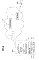
- Fig. 1 is a diagram showing an NGN 10 (IP network) and respective multifunction peripherals (MFPs) 2 (communication terminals).
- NGN 10 IP network
- MFPs multifunction peripherals
- an MFP 2 that transmits image data will sometimes be referred to as a transmission source MFP 2A.
- An MFP 2 to which image data is transmitted will sometimes be referred to as a transmission destination MFP 2B.
- the NGN 10 includes Session Initiation Protocol (SIP) servers 11 and a location server 12.
- SIP Session Initiation Protocol
- the SIP servers 11 relay IP messages and the image data to/from the MFPs 2.
- the MFPs 2 are multifunction peripherals each having a scanner, printer, FAX, and/or other functions.
- An MFP 2 transmits image data to a transmission destination MFP 2 by using the SIP which is a file transfer protocol for the NGN.
- the MFPs 2 each include a display unit 21, an operation input unit 22, a reading unit 23, an image forming unit 24, and a controller 25.
- Fig. 1 only one of the MFPs 2 (2A) is shown with the configuration of the components 21 to 25.
- the other MFP 2 (2B) has the same configuration as that of the one MFP 2 (2A).
- the display unit 21 is a touch panel.
- the display unit 21 displays various screens such as a setting screen under control of the controller 25.
- Examples of the operation input unit 22 include a button and a touch panel.
- the operation input unit 22 accepts user's operation inputs.
- the reading unit 23 includes a charge-coupled device (CCD) image sensor, for example. The reading unit 23 reads an image on a sheet.
- CCD charge-coupled device
- the image forming unit 24 forms an image on a sheet, for example, by forming a toner image on a photosensitive member and transferring the toner image to the sheet.
- the image forming unit 24 may form an image on a sheet by discharging ink from a header onto the sheet.
- the controller 25 controls the entire MFP 2.
- the controller 25 includes a processor 251, an application specific integrated circuit (ASIC) 252, a memory 253, and a hard disk drive (HDD) 254.
- ASIC application specific integrated circuit
- HDD hard disk drive
- the controller 25 makes the MFP 2 perform various functions by the processor 251 reading and processing a program or programs in the memory 253.
- the ASIC 252 may perform part or all of the processing of the processor 251.
- the controller 25 includes, as its functional blocks, a data size calculation unit 261, an acquisition unit 262, a mode setting unit 263, a projection calculation unit 264 (communication speed calculation unit), a display controller 265, and a transmission unit 266.
- the mode setting unit 263 sets the MFP 2 to any one of a communication speed selection mode, a first automatic selection mode (first mode), and a second automatic selection mode (second mode) as a mode during transmission of image data.
- the communication speed selection mode is a mode in which the user selects the communication speed of image data.
- the first automatic selection mode is a mode in which the MFP 2 automatically transmits image data at a communication speed that provides a minimum amount of charge.
- the second automatic selection mode is a mode in which the MFP 2 automatically transmits image data at a maximum communication speed.
- the display controller 265 makes the display unit 21 display a mode selection screen from which the modes can be selected.
- the mode setting unit 263 sets the MFP 2 to a mode accepted by the mode selection screen.
- the user can call the mode selection screen and set a mode to transmit image data before transmitting the image data.
- the MFPs 2 in their initial state shall be set to the communication speed selection mode.
- the transmission source MFP 2A reads an image on a sheet by using the reading unit 23.
- the transmission source MFP 2A stores image data into a page memory, and performs compression processing, addition of header information, etc.
- the transmission source MFP 2A then saves the image data into the HDD 254 (Act1).
- the user may input the image data to be transmitted into the transmission source MFP 2A by using a universal serial bus (USB) or the like.
- USB universal serial bus
- the data size calculation unit 261 calculates the size of the image data to be transmitted stored in the HDD 254 (Act2).
- the acquisition unit 262 acquires speed information on all communication speeds at which the transmission destination MFP 2B can perform communication. Specifically, the acquisition unit 262 inquires of the transmission destination MFP 2B via the SIP servers 11 about communication speeds at which communication can be performed (Act3). If the transmission destination MFP 2B can transmit speed information to the transmission source MFP 2A (Act4: YES), the acquisition unit 262 acquires from the transmission destination MFP 2B side a response including speed information that indicates communication speeds at which the transmission destination MFP 2B can perform communication (Act5). Suppose that in the present embodiment, the acquisition unit 262 acquires speed information indicating communication speeds of 64 kbps, 512 kbps, 1 Mbps, and 2.6 Mbps from the transmission destination MFP 2B.
- the projection calculation unit 264 calculates projected communication times and projected communication fees when transmitting the image data at the communication speeds indicated by the acquired speed information, respectively (Act6).
- the amount of charge is set depending on communication speed.
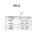
- the memory 253 of the transmission source MFP 2A contains a data table 271 shown in Fig. 4 , in which the amounts of charge are associated with respective communication speeds.
- the projection calculation unit 264 calculates the projected communication fees and projected communication times for the respective communication speeds on the basis of the communication speeds indicated by the acquired speed information, the amounts of charge associated with the respective communication speeds in the data table 271, and the size of the image data. A method of calculating a projected communication fee and a projected communication time will be briefly described below.
- Fig. 4 fees for communication speeds of 64 kbps, 512 kbps, and 1 Mbps are charged in units of 30 sec. Fees for a communication speed of 2.6 Mbps are charged in units of three minutes. With the communication speed of 2.6 Mbps, the projected communication time is 38 sec as mentioned above. The amount of charge is 15 yen / 3 min. Since fees are charged in units of three minutes, 15 yen will be charged for 38 sec which is shorter than three minutes.
- 38 sec shorter than three minutes, is rounded up to three minutes for calculation.
- the fee is calculated for six minutes.
- the projection calculation unit 264 calculates a communication speed that provides a minimum projected communication fee among the communication speeds, and a maximum communication speed among the communication speeds.
- the display controller 265 makes the display unit 21 display a communication speed selection screen 272 shown in Fig. 5 , which includes the calculations of the projection calculation unit 264 (Act8).
- communication speeds are associated with respective projected communication fees and projected communication times. Any one of the communication speeds can be selected in the communication speed selection screen 272.
- the display controller 265 makes a communication speed of the minimum projected communication fee selected.
- the selected communication speed is marked with a black circle. Unselected communication speeds are marked with a white circle.
- the communication speed selection screen 272 includes a transmission button 273 for transmitting image data and a cancel button 274 for canceling image data transmission.
- the display controller 265 may make a maximum communication speed selected. Whether the initial state of the communication speed selection screen 272 takes the state of Fig. 5 where the communication speed of the minimum communication fee is selected or that of Fig. 6 where the maximum communication speed is selected may be set by the user calling an appropriate setting screen.
- the transmission unit 266 transmits the image data at the communication speed accepted through the operation input unit 22 (Act10).
- the transmission source MFP 2A transmits the image data to the transmission destination MFP 2B at the set communication speed of 1 Mbps (Act11).
- the transmission source MFP 2A If the transmission source MFP 2A is set to the first automatic selection mode (Act7: NO, Act 12: YES), the transmission source MFP 2A automatically transmits the image data at the communication speed of 1 Mbps, which provides the minimum amount of charge, without displaying the communication speed selection screen 272 (Act 13).
- the transmission source MFP 2A If the transmission source MFP 2A is set to the second automatic selection mode (Act7: NO, Act12: NO), the transmission source MFP 2A automatically transmits the image data at the maximum communication speed of 2.6 Mbps without displaying the communication speed selection screen 272 (Act14).
- the establishment of the session and the transmission and reception of image data between the transmission source MFP 2A and the transmission destination MFP 2B described above are performed through the SIP servers 11.
- the established date and time and the terminated date and time of the session between the MFPs 2A and 2B and the communication speed at which the image data is transmitted and received are recorded on the SIP servers 11 or other server in the NGN 10.
- the administrator of the SIP servers 11 charges the fee to the user of the transmission source MFP 2A, who is a user of the NGN 10, on the basis of the established date and time and the terminated date and time of the session and the communication speed at which the image data is transmitted and received.
- the SIP servers 11 also have a registrar function of registering position information (such as a uniform resource identifier (URI)) of user agents of the respective MFPs 2A and 2B into the location server 12.
- URI uniform resource identifier
- the transmission source MFP 2A transmits an INVITE message to the transmission destination MFP 2B through the SIP servers 11 when establishing a communication connection between the MFPs 2A and 2B; and the transmission destination MFP 2B transmits "200 OK" to the transmission source MFP 2A as a status code for acknowledging the establishment of the session in response to the INVITE message, whereby a session is established.
- the transmission destination MFP 2B transmits "200 OK" to the transmission source MFP 2A as a status code for acknowledging the establishment of the session in response to the INVITE message, whereby a session is established.
- Fig. 7 is a functional block diagram of the controller 25 of an MFP 2.
- the controller 25 of the transmission source MFP 2A includes an effective speed calculation unit 267 as one of its functional units.
- the effective speed calculation unit 267 calculates the effective speed of communication with the transmission destination MFP 2B. Specifically, the effective speed calculation unit 267 calculates the effective speed of communication by dividing the size of image size by an actual communication time after the transmission source MFP 2A transmits the image data to the transmission destination MFP 2B.
- the effective speed calculation unit 267 stores the calculated effective speed into the memory 253.
- the memory 253 stores a set communication speed, the size of image data, a projected communication time, a projected communication fee, and calculated effective speed as a history each time the transmission source MFP 2A transmits image data to the transmission destination MFP 2B.
- the effective speed calculationunit267 calculatestheeffectivespeed of transmission of image data as a communication speed for the projection calculation unit 264 to use in calculating a projected communication time and a projected communication fee. For example, suppose that when the transmission source MFP 2A transmits image data, there are a plurality of past history records in which the settings of the transmission destination MFP 2B and the communication speed are the same as those in the current transmission of the image data. In such a case, the effective speed calculation unit 267 calculates the average of the effective speeds in those past history records as the effective speed of the current transmission of the image data. The projection calculation unit 264 calculates a projected communication fee and a projected communication time on the basis of the calculated effective speed and the size of the image data.
- a more accurate projected communication time and projected communication fee can be displayed.
- the user can conveniently select a communication speed on the basis of such projections.
- the projection calculation unit 264 calculates both a projected communication fee and a projected communication time when transmitting image data at a communication speed indicated by acquired speed information.
- the projection calculation unit 264 may calculate either one alone.
- the display controller 265 makes the display unit 21 display the projected communication fee or projected communication time calculated by the projection calculation unit 264.
- a recording medium may be of any form as long as the recording medium can store a program and is computer-readable.
- examples of recording media include internal storage devices that are implemented inside a computer, such as a ROM and a RAM, portable storage media such as a CD-ROM, a flexible disk, a DVD disk, a magneto-optical disk, and an IC card, a database that contains a computer program, and other computers and databases thereof.
- Functions obtained by installation or downloading may be implemented in cooperation with an OS or the like inside an apparatus.
- Part or all of a program may be a dynamically-generated execution module or modules.
Landscapes
- Engineering & Computer Science (AREA)
- Multimedia (AREA)
- Signal Processing (AREA)
- Health & Medical Sciences (AREA)
- Biomedical Technology (AREA)
- General Health & Medical Sciences (AREA)
- Telephonic Communication Services (AREA)
- Facsimiles In General (AREA)
- Data Exchanges In Wide-Area Networks (AREA)
- Telephone Function (AREA)
- Facsimile Transmission Control (AREA)
Abstract
Description
- This application is based upon and claims the benefit of priority from
US provisional application 61/475,447, filed on April 14, 2011 - Embodiments described in this specification relate to a communication technology for an IP network.
- Next-generation networks (NGNs) have recently been under development as an alternative to the conventional telephone networks. The NGN is intended to integrate and restructure IP networks for Internet services and telephone networks for telephone services by using initiation protocol(IP) technology.
- At present, when communication terminals connected to an NGN transmit and receive images to/from each other (IP-FAX), the communication speed is fixed to 1 Mbps. Fees are charged according to communication time it takes to complete the communication.
-
-
Fig. 1 is a diagram showing an NGN and respective MFPs according to a first embodiment; -
Fig. 2 is a functional block diagram of a controller; -
Fig. 3 is a flowchart for explaining processing for transmitting image data; -
Fig. 4 is a diagram showing a data table in which the amounts of charge are associated with communication speeds; -
Fig. 5 is a diagram showing a communication speed selection screen; -
Fig. 6 is a diagram showing the communication speed selection screen where a maximum communication speed is selected; and -
Fig. 7 is a functional block diagram of a controller according to a second embodiment. - Typically, a communication terminal according to an embodiment is a communication terminal for transmitting image data to a transmission destination communication terminal through an initiation protocol (IP) network. The communication terminal includes a display unit, a data size calculation unit, an acquisition unit, a projection calculation unit, and a display controller. The data size calculation unit calculates the size of image data to be transmitted. The acquisition unit acquires speed information indicating a communication speed at which communication can be performed with the transmission destination communication terminal. The projection calculation unit calculates at least either one of a projected communication fee and a projected communication time when transmitting the image data at the communication speed indicated by the acquired speed information. The display controller makes the display unit display the result of calculation of the projection calculation unit.
- Embodiments will be described below with reference to the drawings.
-
Fig. 1 is a diagram showing an NGN 10 (IP network) and respective multifunction peripherals (MFPs) 2 (communication terminals). In the following description, anMFP 2 that transmits image data will sometimes be referred to as atransmission source MFP 2A. AnMFP 2 to which image data is transmitted will sometimes be referred to as atransmission destination MFP 2B. - The NGN 10 includes Session Initiation Protocol (SIP)
servers 11 and alocation server 12. When theMFPs 2 connected to the NGN 10 perform transmission and reception of image data to/from each other, theSIP servers 11 relay IP messages and the image data to/from theMFPs 2. - The
MFPs 2 are multifunction peripherals each having a scanner, printer, FAX, and/or other functions. AnMFP 2 transmits image data to atransmission destination MFP 2 by using the SIP which is a file transfer protocol for the NGN. TheMFPs 2 each include adisplay unit 21, anoperation input unit 22, areading unit 23, animage forming unit 24, and acontroller 25. InFig. 1 , only one of the MFPs 2 (2A) is shown with the configuration of thecomponents 21 to 25. The other MFP 2 (2B) has the same configuration as that of the one MFP 2 (2A). - An example of the
display unit 21 is a touch panel. Thedisplay unit 21 displays various screens such as a setting screen under control of thecontroller 25. Examples of theoperation input unit 22 include a button and a touch panel. Theoperation input unit 22 accepts user's operation inputs. Thereading unit 23 includes a charge-coupled device (CCD) image sensor, for example. Thereading unit 23 reads an image on a sheet. - The
image forming unit 24 forms an image on a sheet, for example, by forming a toner image on a photosensitive member and transferring the toner image to the sheet. Theimage forming unit 24 may form an image on a sheet by discharging ink from a header onto the sheet. Thecontroller 25 controls theentire MFP 2. Thecontroller 25 includes aprocessor 251, an application specific integrated circuit (ASIC) 252, amemory 253, and a hard disk drive (HDD) 254. - The
controller 25 makes the MFP 2 perform various functions by theprocessor 251 reading and processing a program or programs in thememory 253. The ASIC 252 may perform part or all of the processing of theprocessor 251. - As shown in
Fig. 2 , thecontroller 25 includes, as its functional blocks, a datasize calculation unit 261, anacquisition unit 262, amode setting unit 263, a projection calculation unit 264 (communication speed calculation unit), adisplay controller 265, and atransmission unit 266. - The
mode setting unit 263 sets theMFP 2 to any one of a communication speed selection mode, a first automatic selection mode (first mode), and a second automatic selection mode (second mode) as a mode during transmission of image data. The communication speed selection mode is a mode in which the user selects the communication speed of image data. The first automatic selection mode is a mode in which theMFP 2 automatically transmits image data at a communication speed that provides a minimum amount of charge. The second automatic selection mode is a mode in which theMFP 2 automatically transmits image data at a maximum communication speed. - The
display controller 265 makes thedisplay unit 21 display a mode selection screen from which the modes can be selected. Themode setting unit 263 sets theMFP 2 to a mode accepted by the mode selection screen. The user can call the mode selection screen and set a mode to transmit image data before transmitting the image data. In the present embodiment, theMFPs 2 in their initial state shall be set to the communication speed selection mode. - Processing for transmitting image data (image data transmission method) will be described below with reference to a flowchart of
Fig. 3 . - The
transmission source MFP 2A reads an image on a sheet by using thereading unit 23. Thetransmission source MFP 2A stores image data into a page memory, and performs compression processing, addition of header information, etc. Thetransmission source MFP 2A then saves the image data into the HDD 254 (Act1). The user may input the image data to be transmitted into thetransmission source MFP 2A by using a universal serial bus (USB) or the like. - The data
size calculation unit 261 calculates the size of the image data to be transmitted stored in the HDD 254 (Act2). - Next, the
acquisition unit 262 acquires speed information on all communication speeds at which thetransmission destination MFP 2B can perform communication. Specifically, theacquisition unit 262 inquires of thetransmission destination MFP 2B via theSIP servers 11 about communication speeds at which communication can be performed (Act3). If thetransmission destination MFP 2B can transmit speed information to thetransmission source MFP 2A (Act4: YES), theacquisition unit 262 acquires from thetransmission destination MFP 2B side a response including speed information that indicates communication speeds at which thetransmission destination MFP 2B can perform communication (Act5). Suppose that in the present embodiment, theacquisition unit 262 acquires speed information indicating communication speeds of 64 kbps, 512 kbps, 1 Mbps, and 2.6 Mbps from thetransmission destination MFP 2B. - The
projection calculation unit 264 calculates projected communication times and projected communication fees when transmitting the image data at the communication speeds indicated by the acquired speed information, respectively (Act6). When using the lines of theNGN 10, the amount of charge is set depending on communication speed. Thememory 253 of thetransmission source MFP 2A contains a data table 271 shown inFig. 4 , in which the amounts of charge are associated with respective communication speeds. Theprojection calculation unit 264 calculates the projected communication fees and projected communication times for the respective communication speeds on the basis of the communication speeds indicated by the acquired speed information, the amounts of charge associated with the respective communication speeds in the data table 271, and the size of the image data. A method of calculating a projected communication fee and a projected communication time will be briefly described below. - The
projection calculation unit 264 calculates a projected communication time according to the following equation (1):
- For example, if the image data to be transmitted has a size of 100 MB, the
projection calculation unit 264 calculates that the projected communication time at a communication speed of 2.6 Mbps is 38 sec, by 100 (MB) ÷ 2.6 (Mbps) = 38 (sec). - The
projection calculation unit 264 calculates a projected communication fee according to the following equation (2):
- As shown in
Fig. 4 , fees for communication speeds of 64 kbps, 512 kbps, and 1 Mbps are charged in units of 30 sec. Fees for a communication speed of 2.6 Mbps are charged in units of three minutes. With the communication speed of 2.6 Mbps, the projected communication time is 38 sec as mentioned above. The amount of charge is 15 yen / 3 min. Since fees are charged in units of three minutes, 15 yen will be charged for 38 sec which is shorter than three minutes. - That is, if the size of the image data is 100 MB and the communication speed is 2.6 Mbps, the
projection calculation unit 264 calculates that the projected communication fee is 15 yen, by projected communication time × the amount of charge = 3 (min) × 15 (yen) / 3 (min) = 15 (yen). Here, 38 sec, shorter than three minutes, is rounded up to three minutes for calculation. Given a projected communication time of 3 min + 38 sec, the fee is calculated for six minutes. - Having calculated the projected communication times and projected communication fees for the respective communication speeds as described above, the
projection calculation unit 264 calculates a communication speed that provides a minimum projected communication fee among the communication speeds, and a maximum communication speed among the communication speeds. - If the
transmission source MFP 2A is set to the communication speed selection mode (Act7: YES), thedisplay controller 265 makes thedisplay unit 21 display a communicationspeed selection screen 272 shown inFig. 5 , which includes the calculations of the projection calculation unit 264 (Act8). In the communicationspeed selection screen 272, communication speeds are associated with respective projected communication fees and projected communication times. Any one of the communication speeds can be selected in the communicationspeed selection screen 272. - In an initial state of the communication
speed selection screen 272 where no user selection has been accepted of a communication speed, thedisplay controller 265 makes a communication speed of the minimum projected communication fee selected. In the communicationspeed selection screen 272 ofFig. 5 , the selected communication speed is marked with a black circle. Unselected communication speeds are marked with a white circle. The communicationspeed selection screen 272 includes atransmission button 273 for transmitting image data and a cancelbutton 274 for canceling image data transmission. - In an initial state of the communication
speed selection screen 272, as shown inFig. 6 , thedisplay controller 265 may make a maximum communication speed selected. Whether the initial state of the communicationspeed selection screen 272 takes the state ofFig. 5 where the communication speed of the minimum communication fee is selected or that ofFig. 6 where the maximum communication speed is selected may be set by the user calling an appropriate setting screen. - When a communication speed is selected in the communication
speed selection screen 272 and theoperation input unit 22 accepts the selection of the transmission button 273 (Act9), thetransmission unit 266 transmits the image data at the communication speed accepted through the operation input unit 22 (Act10). - If the
transmission destination MFP 2B is not able to transmit speed information to thetransmission source MFP 2A (Act4: NO), thetransmission source MFP 2A transmits the image data to thetransmission destination MFP 2B at the set communication speed of 1 Mbps (Act11). - If the
transmission source MFP 2A is set to the first automatic selection mode (Act7: NO, Act 12: YES), thetransmission source MFP 2A automatically transmits the image data at the communication speed of 1 Mbps, which provides the minimum amount of charge, without displaying the communication speed selection screen 272 (Act 13). - If the
transmission source MFP 2A is set to the second automatic selection mode (Act7: NO, Act12: NO), thetransmission source MFP 2A automatically transmits the image data at the maximum communication speed of 2.6 Mbps without displaying the communication speed selection screen 272 (Act14). - The establishment of the session and the transmission and reception of image data between the
transmission source MFP 2A and thetransmission destination MFP 2B described above are performed through theSIP servers 11. The established date and time and the terminated date and time of the session between theMFPs SIP servers 11 or other server in theNGN 10. The administrator of theSIP servers 11 charges the fee to the user of thetransmission source MFP 2A, who is a user of theNGN 10, on the basis of the established date and time and the terminated date and time of the session and the communication speed at which the image data is transmitted and received. Incidentally, theSIP servers 11 also have a registrar function of registering position information (such as a uniform resource identifier (URI)) of user agents of therespective MFPs location server 12. - In the foregoing description, no mention has been made that: the
transmission source MFP 2A transmits an INVITE message to thetransmission destination MFP 2B through theSIP servers 11 when establishing a communication connection between theMFPs transmission destination MFP 2B transmits "200 OK" to thetransmission source MFP 2A as a status code for acknowledging the establishment of the session in response to the INVITE message, whereby a session is established. In the foregoing description, it has also been omitted that a session is established between theMFPs MFPs - Other points omitted in the foregoing description include that the inquiry for speed information and the response are followed by the transmission of the image data, and after the
transmission destination MFP 2B finishes printing or the like, thetransmission destination MFP 2B transmits "BYE" to thetransmission source MFP 2A through theSIP servers 11 as a status code for terminating the session. Another point omitted in the foregoing description is that thetransmission source MFP 2A, receiving the "BYE" message, transmits "200 OK" to thetransmission destination MFP 2B through theSIP servers 11 to terminate the session between theMFPs - The transactions of IP messages between communication terminals in the
NGN 10 in establishing and terminating a session are disclosed in detail in Japanese Patent Application Laid-Open Nos.2009-26130 2010-219688 2010-245617 -
Fig. 7 is a functional block diagram of thecontroller 25 of anMFP 2. - The
controller 25 of thetransmission source MFP 2A according to the present embodiment includes an effectivespeed calculation unit 267 as one of its functional units. The effectivespeed calculation unit 267 calculates the effective speed of communication with thetransmission destination MFP 2B. Specifically, the effectivespeed calculation unit 267 calculates the effective speed of communication by dividing the size of image size by an actual communication time after thetransmission source MFP 2A transmits the image data to thetransmission destination MFP 2B. The effectivespeed calculation unit 267 stores the calculated effective speed into thememory 253. Thememory 253 stores a set communication speed, the size of image data, a projected communication time, a projected communication fee, and calculated effective speed as a history each time thetransmission source MFP 2A transmits image data to thetransmission destination MFP 2B. - Based on such a past transmission history stored in the
memory 253, the effective speed calculationunit267calculatestheeffectivespeed of transmission of image data as a communication speed for theprojection calculation unit 264 to use in calculating a projected communication time and a projected communication fee. For example, suppose that when thetransmission source MFP 2A transmits image data, there are a plurality of past history records in which the settings of thetransmission destination MFP 2B and the communication speed are the same as those in the current transmission of the image data. In such a case, the effectivespeed calculation unit 267 calculates the average of the effective speeds in those past history records as the effective speed of the current transmission of the image data. Theprojection calculation unit 264 calculates a projected communication fee and a projected communication time on the basis of the calculated effective speed and the size of the image data. - In the present embodiment, if a delay occurs during data transmission and reception due to reasons such as heavy traffic on lines, a more accurate projected communication time and projected communication fee can be displayed. The user can conveniently select a communication speed on the basis of such projections.
- The foregoing embodiments have dealt with the cases where the
projection calculation unit 264 calculates both a projected communication fee and a projected communication time when transmitting image data at a communication speed indicated by acquired speed information. However, theprojection calculation unit 264 may calculate either one alone. In such a case, thedisplay controller 265 makes thedisplay unit 21 display the projected communication fee or projected communication time calculated by theprojection calculation unit 264. - A recording medium may be of any form as long as the recording medium can store a program and is computer-readable. Specifically, examples of recording media include internal storage devices that are implemented inside a computer, such as a ROM and a RAM, portable storage media such as a CD-ROM, a flexible disk, a DVD disk, a magneto-optical disk, and an IC card, a database that contains a computer program, and other computers and databases thereof. Functions obtained by installation or downloading may be implemented in cooperation with an OS or the like inside an apparatus. Part or all of a program may be a dynamically-generated execution module or modules.
- The order of processing in the foregoing embodiments may be different from that illustrated in the embodiments.
- As has been described in detail above, according to the technology described in this specification, it is possible to provide a communication technology for an IP network.
- While certain embodiments have been described, these embodiments have been presented by way of example only, and are not intended to limit the scope of invention. Indeed, the novel apparatus, methods and system described herein may be embodied in a variety of other forms; furthermore, various omissions, substitutions and changes in the form of the apparatus, methods and system described herein may be made without departing from the spirit of the inventions. The accompanying claims and their equivalents are intended to cover such forms or modifications as would fall within the scope and spirit of the inventions.
Claims (20)
- A communication terminal configured to transmit image data to a transmission destination communication terminal through an initiation protocol (IP) network, the communication terminal comprising:a display unit;a data size calculation unit configured to calculate a size of image data to be transmitted;an acquisition unit configured to acquire speed information indicating a communication speed at which communication can be performed with the transmission destination communication terminal;a projection calculation unit configured to calculate at least either one of a projected communication fee and a projected communication time when transmitting the image data at the communication speed indicated by the acquired speed information; anda display controller configured to make the display unit display a result of calculation of the projection calculation unit.
- The communication terminal according to claim 1, wherein:the projection calculation unit calculates both the projected communication fee and the projected communication time; andthe display controller makes the display unit display both the projected communication fee and the projected communication time.
- The communication terminal according to claim 1, wherein
if the transmission destination communication terminal can transmit speed information to the communication terminal, the acquisition unit acquires the speed information by inquiring of the transmission destination communication terminal about speed information indicating a communication speed at which communication can be performed with the communication terminal. - The communication terminal according to claim 1, wherein
if the transmission destination communication terminal can perform communication at a plurality of communication speeds, the acquisition unit acquires all speed information indicating the communication speeds at which the transmission destination communication terminal can perform communication. - The communication terminal according to claim 4, further comprising:an operation input unit configured to accept a user's operation input; anda transmission unit configured to transmit the image data to the transmission destination communication terminal, and whereinthe display controller makes the display unit display a selection screen in which the communication speeds indicated by the respective pieces of acquired speed information are associated with at least either projected communication fees or projected communication times, respectively, and on which any one of the communication speeds can be selected, andthe transmission unit transmits the image data at a communication speed that is selected on the selection screen through the operation input unit.
- The communication terminal according to claim 5, wherein:the projection calculation unit calculates a communication speed that provides a minimum projected communication fee among the communication speeds indicated by the respective pieces of acquired speed information when transmitting the image data at the respective communication speeds; andin an initial state where no user selection has been accepted, the display controller makes the display unit display a selection screen in which the communication speed that provides the minimum projected communication fee is selected.
- The communication terminal according to claim 5, wherein
in an initial state where no user selection has been accepted, the display controller makes the display unit display a selection screen in which a maximum communication speed is selected. - The communication terminal according to claim 5, comprising
a mode setting unit configured to set the communication terminal to a mode accepted through the operation input unit between a first mode and a second mode, the first mode being a mode in which a communication speed that provides a minimum projected communication fee is selected in the selection screen of an initial state, the second mode being a mode in which a maximum communication speed is selected in the selection screen of an initial state, and wherein:if the mode setting unit sets the communication terminal to the first mode,the projection calculation unit calculates a communication speed that provides a minimum projected communication fee among the communication speeds indicated by the respective pieces of acquired speed information when transmitting the image data at the respective communication speeds, and the display controller, in an initial state where no user selection has been accepted, makes the display unit display a selection screen in which the communication speed providing the minimum projected communication fee is selected; andif the mode setting unit sets the communication terminal to the second mode,the display controller, in an initial state where no user selection has been accepted, makes the display unit display a selection screen in which a maximum communication speed is selected. - The communication terminal according to claim 1, comprising
an effective speed calculation unit configured to calculate an effective speed of communication with the transmission determination communication terminal, and wherein
the projection calculation unit calculates at least either one of the projected communication fee and the projected communication time on the basis of the effective speed and the size of the image data. - The communication terminal according to claim 1, comprising:a reading unit configured to read an image on a sheet; andan image forming unit configured to form an image on a sheet on the basis of image data.
- The communication terminal according to claim 1, wherein
the IP network is a next-generation network (NGN), and a communication connection between the communication terminal and the transmission destination communication terminal is established by using the Session Initiation Protocol (SIP). - A communication terminal configured to transmit image data to a transmission destination communication terminal through an initiation protocol (IP) network, the communication terminal comprising:a data size calculation unit configured to calculate a size of image data to be transmitted;an acquisition unit configured to acquire speed information indicating communication speeds at which communication can be performed with the transmission destination communication terminal;a communication speed calculation unit configured to calculate a communication speed that provides a minimum projected communication fee among the communication speeds indicated by the acquired speed information when transmitting the image data at the communication speeds indicated by the acquired speed information; anda transmission unit configured to transmit the image data at the calculated communication speed that provides the minimum projected communication fee.
- The communication terminal according to claim 12, wherein
if the transmission destination communication terminal can transmit speed information to the communication terminal, the acquisition unit acquires the speed information by inquiring of the transmission destination communication terminal about speed information indicating a communication speed at which communication can be performed with the communication terminal. - The communication terminal according to claim 12, comprising
an effective speed calculation unit configured to calculate an effective speed of communication with the transmission determination communication terminal, and wherein
the communication speed calculation unit calculates the communication speed that provides the minimum projected communication fee on the basis of the effective speed and the size of the image data. - The communication terminal according to claim 12, wherein
the IP network is a next-generation network (NGN), and a communication connection between the communication terminal and the transmission destination communication terminal is established by using the Session Initiation Protocol (SIP). - A communication terminal configured to transmit image data to a transmission destination communication terminal through an initiation protocol (IP) network, the communication terminal comprising:a data size calculation unit configured to calculate a size of image data to be transmitted;an acquisition unit configured to acquire speed information indicating communication speeds at which communication can be performed with the transmission destination communication terminal; anda transmission unit configured to transmit the image data at a maximum communication speed among the communication speeds indicated by the acquired speed information when transmitting the image data at the communication speeds indicated by the acquired speed information.
- The communication terminal according to claim 16, wherein
if the transmission destination communication terminal can transmit speed information to the communication terminal, the acquisition unit acquires the speed information by inquiring of the transmission destination communication terminal about speed information indicating a communication speed at which communication can be performed with the communication terminal. - The communication terminal according to claim 16, comprising:a reading unit configured to read an image on a sheet; andan image forming unit configured to form an image on a sheet on the basis of image data.
- The communication terminal according to claim 16, wherein
the IP network is a next-generation network (NGN), and a communication connection between the communication terminal and the transmission destination communication terminal is established by using the Session Initiation Protocol (SIP). - An image data transmission method for a communication terminal configured to transmit image data to a transmission destination communication terminal through an initiation protocol (IP) network, the image data transmission method comprising:calculating a size of image data to be transmitted;acquiring speed information indicating a communication speed at which communication can be performed with the transmission destination communication terminal;calculating at least either one of a projected communication fee and a projected communication time when transmitting the image data at the communication speed indicated by the acquired speed information; andmaking a display unit display a result of the calculating.
Applications Claiming Priority (1)
| Application Number | Priority Date | Filing Date | Title |
|---|---|---|---|
| US201161475447P | 2011-04-14 | 2011-04-14 |
Publications (2)
| Publication Number | Publication Date |
|---|---|
| EP2512114A2 true EP2512114A2 (en) | 2012-10-17 |
| EP2512114A3 EP2512114A3 (en) | 2013-10-30 |
Family
ID=46044385
Family Applications (1)
| Application Number | Title | Priority Date | Filing Date |
|---|---|---|---|
| EP12163940.5A Withdrawn EP2512114A3 (en) | 2011-04-14 | 2012-04-12 | Communication terminal connecting to IP network, and image data transmission method |
Country Status (3)
| Country | Link |
|---|---|
| US (1) | US20120262757A1 (en) |
| EP (1) | EP2512114A3 (en) |
| CN (1) | CN102739903A (en) |
Families Citing this family (2)
| Publication number | Priority date | Publication date | Assignee | Title |
|---|---|---|---|---|
| JP6026360B2 (en) * | 2013-06-21 | 2016-11-16 | 京セラドキュメントソリューションズ株式会社 | Image forming method |
| JP2017062708A (en) * | 2015-09-25 | 2017-03-30 | 富士ゼロックス株式会社 | Control device, image processing apparatus, and program |
Citations (3)
| Publication number | Priority date | Publication date | Assignee | Title |
|---|---|---|---|---|
| JP2009026130A (en) | 2007-07-20 | 2009-02-05 | Sony Corp | Communication terminal device, system using the communication terminal device, and information transmission / reception method |
| JP2010219688A (en) | 2009-03-13 | 2010-09-30 | Seiko Epson Corp | Printing apparatus terminal and method of controlling the same |
| JP2010245617A (en) | 2009-04-01 | 2010-10-28 | Seiko Epson Corp | Reception-side terminal, content terminal, content communication system, content reception method, and content transmission method |
Family Cites Families (13)
| Publication number | Priority date | Publication date | Assignee | Title |
|---|---|---|---|---|
| JPS63253765A (en) * | 1987-04-10 | 1988-10-20 | Ricoh Co Ltd | Usage fee display method for data communication terminals |
| JP2539630B2 (en) * | 1987-08-03 | 1996-10-02 | 株式会社リコー | Fax machine |
| JPH08204941A (en) * | 1995-01-31 | 1996-08-09 | Nec Eng Ltd | Fax machine |
| JP3994599B2 (en) * | 1998-10-21 | 2007-10-24 | 富士ゼロックス株式会社 | Recording device and recording method, fee calculation device, fee calculation method, and fee billing system |
| US6502139B1 (en) * | 1999-06-01 | 2002-12-31 | Technion Research And Development Foundation Ltd. | System for optimizing video on demand transmission by partitioning video program into multiple segments, decreasing transmission rate for successive segments and repeatedly, simultaneously transmission |
| US6947388B1 (en) * | 1999-10-20 | 2005-09-20 | International Business Machines Corporation | Method and system for a real-time bandwidth allocation scheduler for media delivery |
| JP2003333271A (en) * | 2002-05-17 | 2003-11-21 | Sharp Corp | Network communication equipment |
| WO2004111749A2 (en) * | 2003-06-11 | 2004-12-23 | Canon Kabushiki Kaisha | Communication apparatus, control method of communication apparatus, and control program of communication apparatus |
| JP2008192070A (en) * | 2007-02-07 | 2008-08-21 | Sharp Corp | Electronic filing system |
| WO2010137073A1 (en) * | 2009-05-28 | 2010-12-02 | 富士通テレコムネットワークス株式会社 | Passive optical network system, station equipment in passive optical network system, and a control method thereof |
| JP5472081B2 (en) * | 2010-12-22 | 2014-04-16 | ブラザー工業株式会社 | Communication device |
| JP5360113B2 (en) * | 2011-03-31 | 2013-12-04 | ブラザー工業株式会社 | Communication apparatus and computer program |
| JP2013115704A (en) * | 2011-11-30 | 2013-06-10 | Canon Inc | Communication device, control method therefor and control program |
-
2012
- 2012-04-12 US US13/444,968 patent/US20120262757A1/en not_active Abandoned
- 2012-04-12 EP EP12163940.5A patent/EP2512114A3/en not_active Withdrawn
- 2012-04-13 CN CN2012101104761A patent/CN102739903A/en active Pending
Patent Citations (3)
| Publication number | Priority date | Publication date | Assignee | Title |
|---|---|---|---|---|
| JP2009026130A (en) | 2007-07-20 | 2009-02-05 | Sony Corp | Communication terminal device, system using the communication terminal device, and information transmission / reception method |
| JP2010219688A (en) | 2009-03-13 | 2010-09-30 | Seiko Epson Corp | Printing apparatus terminal and method of controlling the same |
| JP2010245617A (en) | 2009-04-01 | 2010-10-28 | Seiko Epson Corp | Reception-side terminal, content terminal, content communication system, content reception method, and content transmission method |
Also Published As
| Publication number | Publication date |
|---|---|
| US20120262757A1 (en) | 2012-10-18 |
| CN102739903A (en) | 2012-10-17 |
| EP2512114A3 (en) | 2013-10-30 |
Similar Documents
| Publication | Publication Date | Title |
|---|---|---|
| US8693040B2 (en) | Image processing system, image processing server, and image forming apparatus | |
| JP5962695B2 (en) | Print job distribution / execution system and distribution / execution method, print job distribution server, image forming apparatus, and print control program | |
| JP4045456B2 (en) | Image communication device | |
| US20100296123A1 (en) | Image forming apparatus convenient for user when executable job is restricted due to maintenance operation, method for controlling image forming apparatus and recoding medium recording control program of image forming apparatus | |
| CN104469056A (en) | Information processing system, device, and information processing method | |
| CN110704002A (en) | Information processing apparatus, control method of information processing apparatus, and storage medium | |
| JP5800248B2 (en) | Image processing apparatus and item processing apparatus | |
| CN108173901B (en) | communication device | |
| US20120262757A1 (en) | Communication terminal connecting to ip network, and image data transmission method | |
| US7590857B2 (en) | Secure data processing for image forming apparatus | |
| US20050270564A1 (en) | Printing cost charging method | |
| US20050195425A1 (en) | Email confirmation for specified task at print device | |
| JP2001086284A (en) | Multi-function device, server, and network charging management system | |
| JP2019188731A (en) | Control device, server equipped with control device, and computer program for control device | |
| JP2012194856A (en) | Data communication system, server, and data communication method | |
| JP2019016085A (en) | Information processing device, information processing system and information processing program | |
| JP6682990B2 (en) | Redirection device, printing system and program | |
| JP6804720B2 (en) | Image processing equipment and programs | |
| US20130346145A1 (en) | Communication device, control method therefor, and storage medium storing control program therefor | |
| JP2013191000A (en) | Printing system | |
| JP7056263B2 (en) | Information processing system and information processing method | |
| US20140293365A1 (en) | Facsimile apparatus, control method thereof, and storage medium | |
| US20140320911A1 (en) | Communication apparatus and communication system | |
| EP2458838A1 (en) | Image forming apparatus and facsimile transmitting method thereof | |
| JP2014126877A (en) | Information processor, preview image generation method, and information processing system |
Legal Events
| Date | Code | Title | Description |
|---|---|---|---|
| PUAI | Public reference made under article 153(3) epc to a published international application that has entered the european phase |
Free format text: ORIGINAL CODE: 0009012 |
|
| 17P | Request for examination filed |
Effective date: 20120412 |
|
| AK | Designated contracting states |
Kind code of ref document: A2 Designated state(s): AL AT BE BG CH CY CZ DE DK EE ES FI FR GB GR HR HU IE IS IT LI LT LU LV MC MK MT NL NO PL PT RO RS SE SI SK SM TR |
|
| AX | Request for extension of the european patent |
Extension state: BA ME |
|
| PUAL | Search report despatched |
Free format text: ORIGINAL CODE: 0009013 |
|
| AK | Designated contracting states |
Kind code of ref document: A3 Designated state(s): AL AT BE BG CH CY CZ DE DK EE ES FI FR GB GR HR HU IE IS IT LI LT LU LV MC MK MT NL NO PL PT RO RS SE SI SK SM TR |
|
| AX | Request for extension of the european patent |
Extension state: BA ME |
|
| RIC1 | Information provided on ipc code assigned before grant |
Ipc: H04N 1/333 20060101AFI20130926BHEP Ipc: H04N 1/34 20060101ALI20130926BHEP Ipc: H04N 1/00 20060101ALI20130926BHEP |
|
| STAA | Information on the status of an ep patent application or granted ep patent |
Free format text: STATUS: THE APPLICATION IS DEEMED TO BE WITHDRAWN |
|
| 18D | Application deemed to be withdrawn |
Effective date: 20140501 |