EP2512040A1 - A computation saving echo canceller for a wide band audio signal - Google Patents
A computation saving echo canceller for a wide band audio signal Download PDFInfo
- Publication number
- EP2512040A1 EP2512040A1 EP20110305441 EP11305441A EP2512040A1 EP 2512040 A1 EP2512040 A1 EP 2512040A1 EP 20110305441 EP20110305441 EP 20110305441 EP 11305441 A EP11305441 A EP 11305441A EP 2512040 A1 EP2512040 A1 EP 2512040A1
- Authority
- EP
- European Patent Office
- Prior art keywords
- signal
- sub
- band
- adaptation
- filter
- Prior art date
- Legal status (The legal status is an assumption and is not a legal conclusion. Google has not performed a legal analysis and makes no representation as to the accuracy of the status listed.)
- Granted
Links
- 230000005236 sound signal Effects 0.000 title description 11
- 230000006978 adaptation Effects 0.000 claims abstract description 68
- 230000003044 adaptive effect Effects 0.000 claims abstract description 37
- 238000001914 filtration Methods 0.000 claims abstract description 37
- 238000000034 method Methods 0.000 claims abstract description 12
- 238000005070 sampling Methods 0.000 claims abstract description 10
- 230000008569 process Effects 0.000 claims abstract description 4
- 238000002156 mixing Methods 0.000 claims abstract description 3
- 238000005457 optimization Methods 0.000 claims description 3
- 230000002401 inhibitory effect Effects 0.000 claims 1
- 238000000354 decomposition reaction Methods 0.000 description 11
- 230000015572 biosynthetic process Effects 0.000 description 4
- 230000015556 catabolic process Effects 0.000 description 4
- 238000004891 communication Methods 0.000 description 4
- 238000006731 degradation reaction Methods 0.000 description 4
- 238000010586 diagram Methods 0.000 description 4
- 238000003786 synthesis reaction Methods 0.000 description 4
- 230000002238 attenuated effect Effects 0.000 description 2
- 238000009499 grossing Methods 0.000 description 2
- 238000001228 spectrum Methods 0.000 description 2
- 230000002194 synthesizing effect Effects 0.000 description 2
- 230000001755 vocal effect Effects 0.000 description 2
- 102100021659 ER membrane protein complex subunit 10 Human genes 0.000 description 1
- 101000896290 Homo sapiens ER membrane protein complex subunit 10 Proteins 0.000 description 1
- 101000988287 Senecio vernalis Homospermidine synthase 2 Proteins 0.000 description 1
- 230000008859 change Effects 0.000 description 1
- 238000005516 engineering process Methods 0.000 description 1
- 238000007667 floating Methods 0.000 description 1
- 230000006870 function Effects 0.000 description 1
- 230000007246 mechanism Effects 0.000 description 1
- 230000004048 modification Effects 0.000 description 1
- 238000012986 modification Methods 0.000 description 1
- 238000000926 separation method Methods 0.000 description 1
Images


Classifications
-
- H—ELECTRICITY
- H04—ELECTRIC COMMUNICATION TECHNIQUE
- H04M—TELEPHONIC COMMUNICATION
- H04M9/00—Arrangements for interconnection not involving centralised switching
- H04M9/08—Two-way loud-speaking telephone systems with means for conditioning the signal, e.g. for suppressing echoes for one or both directions of traffic
- H04M9/082—Two-way loud-speaking telephone systems with means for conditioning the signal, e.g. for suppressing echoes for one or both directions of traffic using echo cancellers
-
- H—ELECTRICITY
- H04—ELECTRIC COMMUNICATION TECHNIQUE
- H04M—TELEPHONIC COMMUNICATION
- H04M9/00—Arrangements for interconnection not involving centralised switching
- H04M9/08—Two-way loud-speaking telephone systems with means for conditioning the signal, e.g. for suppressing echoes for one or both directions of traffic
-
- H—ELECTRICITY
- H04—ELECTRIC COMMUNICATION TECHNIQUE
- H04B—TRANSMISSION
- H04B3/00—Line transmission systems
- H04B3/02—Details
- H04B3/20—Reducing echo effects or singing; Opening or closing transmitting path; Conditioning for transmission in one direction or the other
- H04B3/23—Reducing echo effects or singing; Opening or closing transmitting path; Conditioning for transmission in one direction or the other using a replica of transmitted signal in the time domain, e.g. echo cancellers
Definitions
- the present invention generally relates to an echo canceller that can be used in a telecommunication network, for instance in a softphone, or a gateway. It peculiarly concerns an echo cancelling for a wide band audio signal.
- the present invention could be also applied for audio signals at sampling rate higher than 16000 Hz (examples: 22050 Hz, 32000 Hz, 44100 Hz ).
- the echo cancellation is required for audio communication over Internet protocol.
- the use of wide band audio implies the use of wide band echo cancellation.
- the wide band echo cancellation needs a greater computation volume, i. e. a greater number of millions of instructions per second (MIPS), by a factor four. It means that, if a narrow band echo cancellation requires n MIPS, a wide band echo cancellation using the same technology will require 4 x n MIPS. In general, when the band width is doubled the computing volume of echo cancellation is quadrupled.
- the echo cancelling is provided by an echo canceller constituted by a signal processor running echo cancelling software.
- an audio codec used for wide band telephony requires more computation volume than an audio codec for narrow band telephony, the overall computation volume of a softphone is very high.
- a softphone usually runs with other applications at the same time in a personal computer. So it is important to reduce the computation volume of the echo canceller, while providing a high level of audio quality, peculiarly in hand free mode.
- This invention deals with the problem of computation volume of echo cancellation, and proposes an echo canceller to reduce this volume without reducing the quality of the audio signal.
- Figure 1 represents the functional diagram of an example EC1 of such a two sub-band echo canceller according to the prior art.
- This example comprises:
- the two adaptive filters AL and AH are respectively controlled by the corrected signal CRL and CRH so that these corrected signals are minimized, i. e. so that the echo is minimized in each of the sub-bands.
- the higher sub-band spreads from 4000 Hz to 7000 HZ; and the lower sub-band spreads from 50 Hz to 4000 HZ.
- the splitter device SP1 comprises a low-pass filter LP1 and a high pass filter HP1, associated respectively with two sub-sampling devices LSS1 and HSS1.
- the splitter device SP2 comprises a low-pass filter LP2 and a high pass filter HP2, associated respectively with two sub-sampling devices LSS2 and HSS2 for generating respectively the signals RL and RH.
- a low-pass filter LP2 and a high pass filter HP2 associated respectively with two sub-sampling devices LSS2 and HSS2 for generating respectively the signals RL and RH.
- One out of two successive samples of each of the two filtered signals, respectively supplied by the low-pass filter LP2 and the high pass filter HP2 is dropped for constituting respectively the signals RL and RH.
- the mixer device MX comprises:
- the cost of this known solution is slightly greater than half the cost of a full band solution, because the decomposition cost and synthesis cost are very low with respect to the cost of echo filtering and adaptation.
- the same known method can be used for n band decomposition.
- the object of the invention is an echo canceller comprising:
- An echo canceller exploits the nature of voice signal: It decomposes this voice signal in two frequency sub-bands; and it controls the adaptation of the filters corresponding to the two sub-bands, in a way that avoids having adaptation of the two filters simultaneously.
- the computation volume for the adaptation of each of the two filters is very high in comparison with the computation for filtering and other functions of echo cancellation, the global computation volume is drastically reduced.
- Figure 2 shows the spectrum of a typical audio signal that can found in a wide band telephony channel. It spreads from 0 to 8000Hz.
- Classical telephony transmits a narrow band 300 - 3400 Hz.
- Wide band telephony transmits the band 50 - 7000 Hz.
- For splitting the echo cancelling process we will consider a lower sub-band LS covering 50 - 4000 Hz and a higher sub-band HS covering 4000 - 7000 Hz. The greatest part of the energy of this telephony signal is located in the lower sub-band LS (50 - 3400 Hz).
- the lower sub-band LS carries the main part of the audio information. More peculiarly, the band 50 - 300 Hz provides a sense of presence.
- the energy of the signal of the higher sub-band HS (4000 - 8000 Hz) is low, and this part of the signal is similar to noise, but it contributes to enhance the clarity and intelligibility of the restituted audio.
- the audio signal at 4000Hz, and higher is similar to noise and the energy around this frequency is low, regarding the energy in the band 50-3400Hz, the decomposition, into two sub-bands 50 - 4000 Hz and 4000 - 7500 Hz, and the synthesis of a restituted signal have little impact on the quality of the audio signal.
- the basic idea of the invention is to focus more on the processing of lower frequencies than on the processing of higher frequencies, thus saving computation volume.
- the adaptation of the lower band adaptive filter of the echo cancellation is critical.
- the adaptation of the higher band adaptive filter of the echo cancellation is less important.
- the filter of the lower sub-band is adapted.
- no adaptive filter but a simple echo suppressor is applied to the higher sub-band.
- this filter is frozen, and the adaptation of the filter for the higher sub-band is enabled.
- An echo suppressor works by detecting if there is a audio signal going in one direction on a circuit, and then inserting a great deal of loss in the other direction.
- the echo suppressor at the far-end of the circuit adds this loss when it detects audio coming from the near-end of the circuit. This added loss prevents a speaker, located at the near end, from hearing his/her own voice.
- the adaptation mechanism is designed to provide a quick convergence of the filters to an acceptable quality. Once the optimal filter values are reached, there is no need of adaptation, unless there is a modification of the echo.
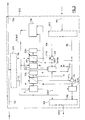
- FIG. 3 represents a block diagram of an embodiment EC2 of the echo canceller according to the invention. This embodiment comprises:
- the splitter device SP1, the splitter device SP2, and the mixer device MX are similar to those known and described with reference to figure 1 .
- the register STL provides, to the control unit CTR, a signal comprising the following information:
- the register STH provides, to the control unit CTR, the following information:
- the information provided by the registers STH and STL is used by the control module CTR to generate the signal SCMD supplied to the control modules CL and HL, respectively for controlling the adaptations of the filters AL and AH for the lower sub-band and the higher sub-band.
- the signal SCMD comprises the following information:
- the control module CL uses the information of the signal SCMD for generating a signal for by-passing or not the non linear processor NLPL, and for generating a signal controlling the filter AL:
- the control module CH uses the information of the signal SCMD for generating a signal for selecting the mode of the non linear processor/echo suppressor NLPL-ES, and for generating a signal controlling the filter AH:
- control module CTR there are two phases:
- control module CTR there are five successive phases with different adaptation modes.
- control means module CTR control the adaptation of the lower sub-band adaptive filter AL and the adaptation of the higher sub-band adaptive filter HL so that these two adaptations are never simultaneous:
- control module CTR unit switches to a "lower sub-band echo cancellation convergence" phase.
- control module CTR switches to an "alternative adaptation" phase.
- the adaptations of filters AL and AH are both enabled, but not at the same time.
- the adaptation of the lower sub-band echo cancellation is enabled 3 times out of 4
- the adaptation of the higher sub-band echo cancellation is enabled once out of 4.
- the higher sub-band filtering is active in a time window where echo is located (Example: if delay found by lower sub-band filter AL is 5 ms, and depth is 16 ms, then filter coefficients from 40 to 167 are activated).
- the lower sub-band filtering is active on the window where echo is located. But its adaptation is permanently disabled.
- the higher sub-band filtering is active on the window where echo is located (Example: if the delay found by the lower sub-band filter AL is 5 ms, and depth is 16 ms, then filter coefficients from 40 to 167 are activated). Its adaptation is permanently enabled.
- the non linear processor/echo suppressor NLP_ES is still in echo suppressor mode.
- control module CTR unit switches to a "quality optimization" phase:
- the lower sub-band filtering and the higher sub-band filtering are both active on the window where echo is located.
- the lower sub-band filtering adaptation is enabled for 1 signal sample out of 2.
- QTH3 Form 24 dB
- the higher sub-band filtering adaptation is enabled on the other sample.
- the quality of the higher sub-band filtering reaches the third threshold QTH3 (For instance 24 dB)
- the higher sub-band filtering adaptation is frozen.
Landscapes
- Engineering & Computer Science (AREA)
- Signal Processing (AREA)
- Computer Networks & Wireless Communication (AREA)
- Cable Transmission Systems, Equalization Of Radio And Reduction Of Echo (AREA)
- Telephone Function (AREA)
Abstract
- means (SP1) for splitting a signal (TXi) transmitted from a near end terminal to a far end terminal, into a sub-sampled signal (TH) corresponding to a higher frequency sub-band of the signal (TXi) transmitted to the far end terminal, and a sub-sampled signal (TL) corresponding to a lower frequency sub-band of the signal (TXi) transmitted to the far end terminal,
- means (SP2) for splitting a signal (RXi) received from a far end terminal into a sub-sampled signal (RH) corresponding to a higher frequency sub-band of the signal (RXi) received from the far end terminal, and a sub-sampled signal (RL) corresponding to a lower frequency sub-band of the signal (RXi) received from the far end terminal,
- a first adaptive filter (AL) for filtering the sub-sampled signal (TL) corresponding to the lower frequency sub-band,
- a second adaptive filter (AH) for filtering the sub-sampled signal (TH) corresponding to the higher frequency sub-band,
- subtracting means (SL, SH) controlling the adaptive filters (AL, AH),
- means (MX) for mixing two process corrected signals (CRL', CRH') and up-sampling the resulting signal,
- control means (CTR, STL, STH) that control the adaptation of the first adaptive filter (AL) and the adaptation of the second adaptive filter (HL) so that these two adaptations are never simultaneous.
Description
- The present invention generally relates to an echo canceller that can be used in a telecommunication network, for instance in a softphone, or a gateway. It peculiarly concerns an echo cancelling for a wide band audio signal. The present invention could be also applied for audio signals at sampling rate higher than 16000 Hz (examples: 22050 Hz, 32000 Hz, 44100 Hz ...).
- The echo cancellation is required for audio communication over Internet protocol. The use of wide band audio implies the use of wide band echo cancellation. In order to achieve the same effectiveness as narrow band echo cancellation, in terms of quality, the wide band echo cancellation needs a greater computation volume, i. e. a greater number of millions of instructions per second (MIPS), by a factor four. It means that, if a narrow band echo cancellation requires n MIPS, a wide band echo cancellation using the same technology will require 4 x n MIPS. In general, when the band width is doubled the computing volume of echo cancellation is quadrupled.
- In a softphone, or a gateway, the echo cancelling is provided by an echo canceller constituted by a signal processor running echo cancelling software. As an audio codec used for wide band telephony requires more computation volume than an audio codec for narrow band telephony, the overall computation volume of a softphone is very high. In addition, a softphone usually runs with other applications at the same time in a personal computer. So it is important to reduce the computation volume of the echo canceller, while providing a high level of audio quality, peculiarly in hand free mode.
- This invention deals with the problem of computation volume of echo cancellation, and proposes an echo canceller to reduce this volume without reducing the quality of the audio signal.
-
- 1) There are several known methods to reduce the computation volume of wide band echo cancellation. These methods are based on sub-band decomposition, or frequency domain computation. But these methods introduce:
- An extra delay in the communication, which increases with the number of sub-bands. This delay is important for more than two sub-bands.
- A degradation of audio quality (for more than two sub-bands). This degradation is due to an imperfect separation of the sub-bands (because no filter is ideal).
- 2) There are also known methods avoiding these drawbacks. These methods are based on sub-band decomposition and sub-band filter adaptation. They consist in synthesizing a full band filter by using two sub-band filters. These methods are called delay less decomposition. They are not good enough because:
- They imply the use of Fast Fourier Transforms (FFT) and inverse Fast Fourier Transforms (iFFT) to synthesize the full band filter. They need extra computation because the computation of FFT and iFFT must be done with floating point coding of numbers.
- They introduce a problem of quality, due to the synthesis of the full band filter, peculiarly with fixed point coding of numbers computing.
- 3) Among known methods based on sub-band decomposition, decomposition in two sub-bands enables to reduce the computing by a factor of about 2 (less than 2 in fact). For the wide band audio signal, this decomposition does not introduce a subjective degradation of the quality. But it would be desirable to reduce the computation volume more significantly.
-
Figure 1 represents the functional diagram of an example EC1 of such a two sub-band echo canceller according to the prior art. This example comprises: - An input receiving a signal TXi from the near end terminal.
- An output sending a signal TXo to the far end terminal, this signal being identical to the signal TXi received from the near end terminal.
- An input receiving a signal RXi composed of a vocal signal captured by the far end terminal and an echo originating from the near end terminal and coming back via the far end terminal.
- An output sending a signal RXo to the near end terminal. The echo is cancelled or at least attenuated in this signal Rxo.
- A splitter device SP1 for separating the signal TXi into two sub-sampled signals TH and TL respectively corresponding to a higher sub-band and a lower sub-band.
- Two adaptive filters AL and AH for respectively filtering the two signals TH and TL respectively corresponding to the higher sub-band and the lower sub-band.
- These filters supply filtered signals FTL and FTH respectively.
- A splitter device SP2 for separating the signal RXi into two sub-sampled signals RH and RL respectively corresponding to the higher sub-band and the lower sub-band.
- A first subtractor SH for subtracting the signal FTH to the signal RH, the resulting signal being a corrected signal CRH for the higher sub-band.
- A second subtractor SL for subtracting the signal FTL to the signal RL, the resulting signal being a corrected signal CRL for the lower sub-band.
- A mixer device MX for constituting the signal RXo by up-sampling, combining and smoothing the two corrected signals CRH and CRL.
- The two adaptive filters AL and AH are respectively controlled by the corrected signal CRL and CRH so that these corrected signals are minimized, i. e. so that the echo is minimized in each of the sub-bands. For instance, the higher sub-band spreads from 4000 Hz to 7000 HZ; and the lower sub-band spreads from 50 Hz to 4000 HZ.
- The splitter device SP1 comprises a low-pass filter LP1 and a high pass filter HP1, associated respectively with two sub-sampling devices LSS1 and HSS1. One out of two successive samples of each of the two filtered signals, respectively supplied by the low-pass filter LP1 and the high pass filter HP1, is dropped for constituting respectively the signals TL and TH.
- The splitter device SP2 comprises a low-pass filter LP2 and a high pass filter HP2, associated respectively with two sub-sampling devices LSS2 and HSS2 for generating respectively the signals RL and RH. One out of two successive samples of each of the two filtered signals, respectively supplied by the low-pass filter LP2 and the high pass filter HP2, is dropped for constituting respectively the signals RL and RH.
- The mixer device MX comprises:
- two up-samplers HUS and LUS for respectively up-sampling the corrected signals CRH and CRL, by duplicating each sample;
- a high pass filter HP3 for filtering the signal restituted by the up-sampler HUS;
- a low pass filter LP3 for filtering the signal restituted by the up-sampler LUS;
- an adder device AO for adding the two filtered signals respectively supplied by the filters HP3 and LP3, and generating the output signal RXo to be supplied to the near end terminal.
- The computation volume for removing echo in each sub-band (in this example) is reduced by a factor four, due to a down-sampling factor equal to two. But there is an additional cost for decomposing the signals into two sub-bands and then synthesizing a complete signal. So the cost of this solution is:
- 2 x (Full Band cost)/ 4 + Decomposition Cost + Synthesis Cost
- The cost of this known solution is slightly greater than half the cost of a full band solution, because the decomposition cost and synthesis cost are very low with respect to the cost of echo filtering and adaptation. The same known method can be used for n band decomposition.
- For the wide band audio signal, this decomposition does not introduce a subjective degradation of the quality. But it would be desirable to reduce the computation volume more significantly.
- Thus, there is a need to provide a technical solution for further reducing the computing volume of the echo cancellation for wide band audio communication. This point is particularly important for mobile device and also multichannel echo canceller used on gateways. This can be solved by the echo canceller according to the invention.
- The object of the invention is an echo canceller comprising:
- means for splitting a signal transmitted from a near end terminal to a far end terminal, into a sub-sampled signal corresponding to a higher frequency sub-band of the signal transmitted to the far end terminal, and a sub-sampled signal corresponding to a lower frequency sub-band of the signal transmitted to the far end terminal,
- means for splitting a signal received from a far end terminal into a sub-sampled signal corresponding to a higher frequency sub-band of the signal received from the far end terminal, and a sub-sampled signal corresponding to a lower frequency sub-band of the signal received from the far end terminal,
- a first adaptive filter for filtering the sub-sampled signal corresponding to the lower frequency sub-band of the signal transmitted to the far end terminal, and restituting a first filtered signal,
- a second adaptive filter for filtering the sub-sampled signal corresponding to the higher frequency sub-band of the signal transmitted to the far end terminal, and restituting a second filtered signal,
- first means for subtracting the first filtered signal from the sub-sampled signal corresponding to a lower frequency sub-band out of the signal received from a far end terminal, and supplying a first corrected signal,
- second means for subtracting the second filtered signal from the sub-sampled signal corresponding to a higher frequency sub-band of the signal received from a far end terminal, and supplying a second corrected signal, and for controlling the adaptive filters so that the filtered signals supplied by the first and the second adaptive filters are respectively minimized,
- means for respectively processing the first and the second corrected signals and supplying two processed corrected signal respectively corresponding to the lower and the higher frequency sub-band,
- means for mixing the two process corrected signals and up-sampling the resulting signal, in order to constitute an output signal to be supplied to a near end terminal;
- An echo canceller according to the invention exploits the nature of voice signal: It decomposes this voice signal in two frequency sub-bands; and it controls the adaptation of the filters corresponding to the two sub-bands, in a way that avoids having adaptation of the two filters simultaneously. As the computation volume for the adaptation of each of the two filters is very high in comparison with the computation for filtering and other functions of echo cancellation, the global computation volume is drastically reduced.
- Other features and advantages of the present invention will become more apparent from the following detailed description of embodiments of the present invention, when taken in conjunction with the accompanying drawings.
- In order to illustrate in detail features and advantages of embodiments of the present invention, the following description will be with reference to the accompanying drawings. If possible, like or similar reference numerals designate the same or similar components throughout the figures thereof and description, in which:
-
Figure 1 , described above, represents the functional diagram of an example of a two sub-band echo canceller according to the prior art. -
Figure 2 shows the spectrum of a typical audio signal that can found in a wide band telephony channel. -
Figure 3 represents a block diagram of an embodiment of the echo canceller according to the invention. -
Figure 2 shows the spectrum of a typical audio signal that can found in a wide band telephony channel. It spreads from 0 to 8000Hz. Classical telephony transmits a narrow band 300 - 3400 Hz. Wide band telephony transmits the band 50 - 7000 Hz. For splitting the echo cancelling process, we will consider a lower sub-band LS covering 50 - 4000 Hz and a higher sub-band HS covering 4000 - 7000 Hz. The greatest part of the energy of this telephony signal is located in the lower sub-band LS (50 - 3400 Hz). The lower sub-band LS carries the main part of the audio information. More peculiarly, the band 50 - 300 Hz provides a sense of presence. The energy of the signal of the higher sub-band HS (4000 - 8000 Hz) is low, and this part of the signal is similar to noise, but it contributes to enhance the clarity and intelligibility of the restituted audio. - As the audio signal at 4000Hz, and higher, is similar to noise and the energy around this frequency is low, regarding the energy in the band 50-3400Hz, the decomposition, into two sub-bands 50 - 4000 Hz and 4000 - 7500 Hz, and the synthesis of a restituted signal have little impact on the quality of the audio signal. The basic idea of the invention is to focus more on the processing of lower frequencies than on the processing of higher frequencies, thus saving computation volume. The adaptation of the lower band adaptive filter of the echo cancellation is critical. The adaptation of the higher band adaptive filter of the echo cancellation is less important.
- According to the invention, during the convergence time, only the filter of the lower sub-band is adapted. During this convergence time, no adaptive filter but a simple echo suppressor is applied to the higher sub-band. Once the filter of the lower sub-band has reached acceptable quality, this filter is frozen, and the adaptation of the filter for the higher sub-band is enabled. An echo suppressor works by detecting if there is a audio signal going in one direction on a circuit, and then inserting a great deal of loss in the other direction. Usually the echo suppressor at the far-end of the circuit adds this loss when it detects audio coming from the near-end of the circuit. This added loss prevents a speaker, located at the near end, from hearing his/her own voice.
- The adaptation mechanism is designed to provide a quick convergence of the filters to an acceptable quality. Once the optimal filter values are reached, there is no need of adaptation, unless there is a modification of the echo.
-
Figure 3 represents a block diagram of an embodiment EC2 of the echo canceller according to the invention. This embodiment comprises: - An input receiving a signal TXi to be transmitted from a near end terminal to a far end terminal.
- An output sending a signal TXo to the far end speaker, this signal being identical to the signal TXi received from the near end terminal.
- An input receiving a signal RXi from the far end terminal, this signal being composed of a vocal signal captured by the far end terminal and an echo originating from the near end terminal and coming back via the far end terminal.
- An output supplying a signal RXo, to the near end terminal, wherein the echo has been attenuated.
- A splitter device SP1 for separating the signal TXi into two signals TH and TL respectively corresponding to a higher sub-band (50 - 4000 Hz in this example) and a lower sub-band (4000 - 7500 Hz in this example).
- Two adaptive filters AL and AH for filtering respectively the two signals TH and TL, and supplying filtered signals FTL and FTH respectively corresponding to the lower sub-band and the higher sub-band.
- A splitter device SP2 for separating the signal RXi into two signals RH and RL respectively corresponding to the higher sub-band and the lower sub-band.
- A first subtractor SH for subtracting the signal FTH from the signal RH, the resulting signal being a corrected signal CRH for the higher sub-band.
- A second subtractor SL for subtracting the signal FTL from the signal RL, the resulting signal being a corrected signal CRL for the lower sub-band.
- A first non linear processor/echo suppressor NLPH-ES for processing the signal CRH, receiving the signal TH and the corrected signal CRH, and supplying a processed corrected signal CRH' for the higher sub-band.
- A second non linear processor NLPL for processing the signal CRL and supplying a processed corrected signal CRL' for the lower sub-band.
- A classical mixer device MX for constituting the signal RXo by up-sampling, combining, and smoothing the two processed corrected signals CRH' and CRL'.
- A control module CH supplying commands to the filter AH and to the non linear processor NLPH-ES.
- A control module CL supplying commands to the filter AL and to the non linear processor NLPL.
- A register STH receiving the current status of the filter AH, for the higher sub-band.
- A register STL receiving the current status of the filter AL, for the lower sub-band.
- A control module CTR receiving a signal from the register STH and a signal from the register STL, and supplying a signal SCMD to the control modules CL and CH.
- A classical talk detector DTD, receiving the signal RL supplied by the splitter SP2 and the signal TL supplied by the splitter SP1, for the lower sub-band, and supplying to the register STL a signal indicating whether the received signal RXi represents: a double talk, a single talk, or no talk.
- The splitter device SP1, the splitter device SP2, and the mixer device MX are similar to those known and described with reference to
figure 1 . - The register STL provides, to the control unit CTR, a signal comprising the following information:
- Double Talk, or Single Talk, or No Talk.
- Current filter quality (the enhancement of the filter in measured in dB: difference between CRL and RL during far end user single talk) for the lower sub-band.
- Current estimated delay of the echo (between signals TXo and RXi)
- Current estimated ERL (Echo Return Loss: difference between TL and RL when far end user is speaking alone).This estimation could vary during the communication if the echo varies. It will be used in the higher sub-band processing to speed up the convergence, if needed. It will be also used by the non linear processor/echo suppressor NLPH-ES to set a threshold for energy comparison when it is used as an echo suppressor.
- The register STH provides, to the control unit CTR, the following information:
- Current filter quality (the enhancement of the filter in measured in dB: difference between CRH and RH during far end user single talk) for the higher sub-band.
- Current estimated ERL in the High Band (Echo Return Loss: difference between TH and RH when far end user is speaking alone).
- The information provided by the registers STH and STL is used by the control module CTR to generate the signal SCMD supplied to the control modules CL and HL, respectively for controlling the adaptations of the filters AL and AH for the lower sub-band and the higher sub-band.
- The signal SCMD comprises the following information:
- A command to enable or disable adaptation (The control module CTR uses the status of the filters AL and AH to make a decision: enable or disable adaptation).
- Gain of the adaptation.
- Current estimated ERL.
- Estimated delay and estimated depth of the echo: They are used to focus higher sub-band echo processing on the characteristics of echo already found by the lower sub-band echo processing. So, it also saves computation, because no extra MIPS are used to estimate characteristics the echo again.
- A binary command to choose the mode of the non linear processor/echo suppressor NLPH-ES: classical mode or echo suppressor mode.
- Status of filter quality (the enhancement of the filter in measured in dB).
- The control module CL uses the information of the signal SCMD for generating a signal for by-passing or not the non linear processor NLPL, and for generating a signal controlling the filter AL:
- To enable or disable adaptation in the filter AL.
- To set the gain of the adaptation in the filter AL (This gain has a critical impact on the quality of the filter and on convergence speed).
- The control module CH uses the information of the signal SCMD for generating a signal for selecting the mode of the non linear processor/echo suppressor NLPL-ES, and for generating a signal controlling the filter AH:
- To enable or disable adaptation in the filter AH.
- To set the gain of the adaptation in the filter AH (This gain has a critical impact on the quality of the filter and on convergence speed).
- According to a basic implementation of the control module CTR, there are two phases:
- 1) During a convergence phase, the adaptation of the adaptive filter AL for the lower sub-band is controlled by the corrected signal CRL so that the corrected signal CRL is minimized, i. e. so that the echo is minimized in the lower sub-band; and the adaptation of the adaptive filter AH for the higher sub-band is inhibited. This filter AH is blocked. The non linear processor/echo suppressor NLPH-ES is controlled by a binary control signal supplied by the control module CH so that it behaves like a mere echo suppressor: It receives the signals TH and CRH corresponding to the higher sub-band. It compares the energy of the signal TH and the energy of the signal CRH with a variable threshold ESTH. In order to suppress the echo, it suppresses the signal CRH if the energy of the signal TH is greater than the energy of the signal CRH plus the threshold ESTH. In this phase FTH = 0 and CRH = RH
- 2) After the convergence phase, the two adaptive filters AL and AH, and the non linear processor/echo suppressor NLPH-ES, are respectively controlled by the corrected signal CRL and CRH so that these corrected signals are minimized, and the i. e. so that the echo is minimized in both sub-bands. The non linear processor/echo suppressor NLPH-ES is controlled by the binary control signal supplied by the control module CH so that it behaves like a classical non linear processor associated to an adaptive filter.
- According to a more elaborated implementation of the control module CTR, there are five successive phases with different adaptation modes. However, the control means module CTR control the adaptation of the lower sub-band adaptive filter AL and the adaptation of the higher sub-band adaptive filter HL so that these two adaptations are never simultaneous:
-
- Lower sub-band filtering is active. The adaptation of the filter AL is permanently enabled. The filter AL is only adapted according to the information (Double Talk, or Single Talk, or No Talk) supplied by the talk detector DTD.
- Higher sub-band filtering is permanently disabled. The adaptation of the filter AH is disabled. The non linear processor/echo suppressor NLP_ES is in echo suppressor mode. The threshold ESTH is set at 6dB for instance (Value supplied at initialization of suppressor mode).
- Then the control module CTR unit switches to a "lower sub-band echo cancellation convergence" phase.
-
- The lower sub-band filtering is active. The adaptation of the filter AL is permanently enabled. The filter AL is adapted according to the information (Double Talk, or Single Talk, or No Talk) supplied by the talk detector DTD.
- The higher sub-band filtering is permanently disabled. The non linear processor/echo suppressor NLP_ES is in echo suppressor mode. The threshold ESTH is updated according to the estimated ERL, according to the formula:
- ESTH = Estimated ERL - Marge (Marge = 1dB for example)
- This phase lasts until the quality of lower sub-band filtering reaches a first threshold QTH1 (For instance 15 dB), i. e. when:
- The energy of the signal TL has become greater than the energy of the signal CRL plus a quality threshold QTH1,
- and the echo has been located (Example: The filter AL has determined that the delay is equal to 5 ms, and the depth is equal to 16 ms).
- Then the control module CTR switches to an "alternative adaptation" phase.
- In this phase, the adaptations of filters AL and AH are both enabled, but not at the same time. Preferably, the adaptation of the lower sub-band echo cancellation is enabled 3 times out of 4, and the adaptation of the higher sub-band echo cancellation is enabled once out of 4.
- The higher sub-band filtering is active in a time window where echo is located (Example: if delay found by lower sub-band filter AL is 5 ms, and depth is 16 ms, then filter coefficients from 40 to 167 are activated). The non linear processor/echo suppressor NLP_ES is in echo suppressor mode. Its threshold is ESTH = Estimated ERL - Marge.
- The control module CTR unit switches to a "High Band echo convergence" phase when the quality of the lower sub-band filtering reaches a second threshold QTH2: Energy of TL > Energy of CRL + QTH2 (For instance, QTH2 = 20 dB)
- The lower sub-band filtering is active on the window where echo is located. But its adaptation is permanently disabled.
- The higher sub-band filtering is active on the window where echo is located (Example: if the delay found by the lower sub-band filter AL is 5 ms, and depth is 16 ms, then filter coefficients from 40 to 167 are activated). Its adaptation is permanently enabled.
- The non linear processor/echo suppressor NLP_ES is still in echo suppressor mode.
- ESTH = Estimated ERL - Marge
- When the quality of higher sub-band filtering reaches the second threshold (QTH2), the control module CTR unit switches to a "quality optimization" phase:
- Energy of TH > Energy of CRH + QTH2 (For instance, QTH2 = 20 dB)
- The lower sub-band filtering and the higher sub-band filtering are both active on the window where echo is located. The lower sub-band filtering adaptation is enabled for 1 signal sample out of 2. When the quality of the lower sub-band filtering quality reaches a third threshold QTH3 (For instance 24 dB), the lower sub-band filtering adaptation is frozen.
- The higher sub-band filtering adaptation is enabled on the other sample. When the quality of the higher sub-band filtering reaches the third threshold QTH3 (For instance 24 dB), then the higher sub-band filtering adaptation is frozen.
- If the characteristics of echo change, while the adaptation is frozen for one of the filters AL and HL, then the control unit CTR unit switches back to the phase "Lower sub-band echo convergence".
Claims (5)
- A wide band echo canceller (EC2) comprising:- means (SP1) for splitting a signal (TXi) transmitted from a near end terminal to a far end terminal, into a sub-sampled signal (TH) corresponding to a higher frequency sub-band of the signal (TXi) transmitted to the far end terminal, and a sub-sampled signal (TL) corresponding to a lower frequency sub-band of the signal (TXi) transmitted to the far end terminal,- means (SP2) for splitting a signal (RXi) received from a far end terminal into a sub-sampled signal (RH) corresponding to a higher frequency sub-band of the signal (RXi) received from the far end terminal, and a sub-sampled signal (RL) corresponding to a lower frequency sub-band of the signal (RXi) received from the far end terminal,- a first adaptive filter (AL) for filtering the sub-sampled signal (TL) corresponding to the lower frequency sub-band of the signal (TXi) transmitted to the far end terminal, and restituting a first filtered signal (FTL),- a second adaptive filter (AH) for filtering the sub-sampled signal (TH) corresponding to the higher frequency sub-band of the signal (TXi) transmitted to the far end terminal, and restituting a second filtered signal (FTH),- first means (SL) for subtracting the first filtered signal (FTL) from the sub-sampled signal (RL) corresponding to a lower frequency sub-band out of the signal (RXi) received from a far end terminal, and supplying a first corrected signal (CRL),- second means (SH) for subtracting the second filtered signal (FTH) from the sub-sampled signal (RH) corresponding to a higher frequency sub-band of the signal (RXi) received from a far end terminal, and supplying a second corrected signal (CRH), and for controlling the adaptive filters (AL, AH) so that the filtered signals (CRL, CRH) supplied by the first and the second adaptive filters (AL, AH) are respectively minimized,- means (NLPL, NLPH-ES) for respectively processing the first and the second corrected signals (CRH, CRL) and supplying two processed corrected signal (CRL', CRH') respectively corresponding to the lower and the higher frequency sub-band,- means (MX) for mixing the two process corrected signals (CRL', CRH') and up-sampling the resulting signal, in order to constitute an output signal (RXo) to be supplied to a near end terminal;characterized in that it further comprises control means (CTR, STL, STH) that control the adaptation of the first adaptive filter (AL) and the adaptation of the second adaptive filter (HL) so that these two adaptations are never simultaneous.
- A wide band echo canceller according to claim 1, wherein said control means (CTR, STL, STH) comprise:- means (STL) for detecting when the adaptation of the first adaptive filter (AL) has converged,- means (CTR) for inhibiting the adaptation of the second adaptive filter (AH) as long as the adaptation of the first adaptive filter (AL) has not converged,- and means (CTR) for enabling the adaptation of the second adaptive filter (AH) as soon as the adaptation of the first adaptive filter (AL) has converged.
- A wide band echo canceller according to claim 1, wherein said control means (CTR, STL, STH) comprise:a) means (CTR) for controlling an initialization phase where:- the adaptation of the first filter (AL) is permanently enabled,- the adaptation of the second filter (AH) is permanently disabled;b) means (CTR) for controlling a lower sub-band echo cancellation convergence phase where:- the adaptation of the first filter (AL) is permanently enabled,- the adaptation of the second filter (AH) is permanently disabled until the quality of lower sub-band filtering reaches a predetermined threshold;c) means (CTR) for controlling an alternate adaptation phase where:- the adaptation of the first filter (AL) and the adaptation of the second filter (AH) are both enabled, but not at the same time, until the quality of the lower sub-band filtering reaches a predetermined threshold;d) means (CTR) for controlling a high sub-band echo convergence phase where:- the adaptation of the first filter (AL) is permanently disabled,- the adaptation of the second filter (AH) is permanently enabled until the quality of the higher sub-band filtering reaches predetermined threshold;e) means (CTR) for controlling a quality optimization phase where:- the adaptation of the first filter (AL) is enabled one signal sample out of two, until the quality of the lower sub-band filtering reaches a predetermined threshold, then the lower sub-band filtering adaptation is frozen,- the adaptation of the second filter (AH) is enabled on the other signal sample, until the quality of the higher sub-band filtering reaches a predetermined threshold, then the higher sub-band filtering adaptation is frozen.
- A wide band echo canceller according to claim 1, wherein said control means (CTR, STL, STH) comprise means for enabling the adaptation of the first filter (AL) for three signal samples out of four, and enabling the adaptation of the second adaptive filter (AH) for one signal sample out of four..
- A wide band echo canceller according to claim 1, that further comprises means (CTR ) for replacing the second adaptive filter (AH) by an echo suppressor (NLP-ES) as long as the second adaptive filter (AH) is disabled.
Priority Applications (6)
| Application Number | Priority Date | Filing Date | Title |
|---|---|---|---|
| EP20110305441 EP2512040B1 (en) | 2011-04-14 | 2011-04-14 | A computation saving echo canceller for a wide band audio signal |
| CN201280017553.7A CN103460613B (en) | 2011-04-14 | 2012-01-11 | A computation saving echo canceller for a wide band audio signal |
| JP2014504212A JP5695268B2 (en) | 2011-04-14 | 2012-01-11 | Computational saving echo canceller for wideband audio signals |
| KR1020137026968A KR101445999B1 (en) | 2011-04-14 | 2012-01-11 | A computation saving echo canceller for a wide band audio signal |
| US14/007,864 US9143621B2 (en) | 2011-04-14 | 2012-01-11 | Computation saving echo canceller for a wide band audio signal |
| PCT/EP2012/050374 WO2012139780A1 (en) | 2011-04-14 | 2012-01-11 | A computation saving echo canceller for a wide band audio signal |
Applications Claiming Priority (1)
| Application Number | Priority Date | Filing Date | Title |
|---|---|---|---|
| EP20110305441 EP2512040B1 (en) | 2011-04-14 | 2011-04-14 | A computation saving echo canceller for a wide band audio signal |
Publications (2)
| Publication Number | Publication Date |
|---|---|
| EP2512040A1 true EP2512040A1 (en) | 2012-10-17 |
| EP2512040B1 EP2512040B1 (en) | 2013-11-13 |
Family
ID=44351652
Family Applications (1)
| Application Number | Title | Priority Date | Filing Date |
|---|---|---|---|
| EP20110305441 Not-in-force EP2512040B1 (en) | 2011-04-14 | 2011-04-14 | A computation saving echo canceller for a wide band audio signal |
Country Status (6)
| Country | Link |
|---|---|
| US (1) | US9143621B2 (en) |
| EP (1) | EP2512040B1 (en) |
| JP (1) | JP5695268B2 (en) |
| KR (1) | KR101445999B1 (en) |
| CN (1) | CN103460613B (en) |
| WO (1) | WO2012139780A1 (en) |
Families Citing this family (13)
| Publication number | Priority date | Publication date | Assignee | Title |
|---|---|---|---|---|
| CN102571655B (en) * | 2012-01-21 | 2014-12-17 | 华为技术有限公司 | Method and device for implementing interference cancellation and filters |
| CN103347138A (en) * | 2013-06-21 | 2013-10-09 | 苏州鼎富软件科技有限公司 | Cyber dialogue echo eliminating method |
| CN103618835A (en) * | 2013-12-13 | 2014-03-05 | 惠州Tcl移动通信有限公司 | Method and system for automatically switching scene mode according to magnitude of peripheral noise |
| CN104751854A (en) * | 2013-12-26 | 2015-07-01 | 联芯科技有限公司 | Broadband acoustic echo cancellation method and system |
| CN105096960A (en) * | 2014-05-12 | 2015-11-25 | 阿尔卡特朗讯 | Packet-based acoustic echo cancellation method and device for realizing wideband packet voice |
| CN104202050B (en) * | 2014-08-20 | 2017-08-08 | 中国科学院微电子研究所 | A Non-Uniform Sampling Circuit with Multiple Channels and Multiple Slopes |
| KR102263700B1 (en) * | 2015-08-06 | 2021-06-10 | 삼성전자주식회사 | Terminal and method for operaing terminal |
| CN107786755B (en) * | 2016-08-30 | 2020-12-15 | 合肥君正科技有限公司 | Double-end call detection method and device |
| US10117021B1 (en) * | 2017-03-31 | 2018-10-30 | Polycom, Inc. | Audio feedback reduction utilizing adaptive filters and nonlinear processing |
| CN110176244B (en) * | 2018-06-19 | 2023-10-03 | 腾讯科技(深圳)有限公司 | Echo cancellation method, device, storage medium and computer equipment |
| CN108986836A (en) * | 2018-08-29 | 2018-12-11 | 质音通讯科技(深圳)有限公司 | A kind of control method of echo suppressor, device, equipment and storage medium |
| CN109509482B (en) * | 2018-12-12 | 2022-03-25 | 北京达佳互联信息技术有限公司 | Echo cancellation method, echo cancellation device, electronic apparatus, and readable medium |
| CN110310653A (en) * | 2019-07-09 | 2019-10-08 | 杭州国芯科技股份有限公司 | A kind of echo cancel method |
Citations (2)
| Publication number | Priority date | Publication date | Assignee | Title |
|---|---|---|---|---|
| WO2005062595A1 (en) * | 2003-12-23 | 2005-07-07 | Tandberg Telecom As | System and method for enhanced stereo audio |
| WO2007021722A2 (en) * | 2005-08-10 | 2007-02-22 | Clarity Technologies, Inc. | Method and system for clear signal capture |
Family Cites Families (10)
| Publication number | Priority date | Publication date | Assignee | Title |
|---|---|---|---|---|
| JPH0795711B2 (en) * | 1984-11-19 | 1995-10-11 | 松下電器産業株式会社 | Echo signal canceller |
| JPS62132442A (en) * | 1985-12-04 | 1987-06-15 | Matsushita Electric Ind Co Ltd | Echo cancellation method |
| JPH08321796A (en) * | 1995-05-26 | 1996-12-03 | Hitachi Ltd | Acoustic echo canceller |
| JP3403549B2 (en) * | 1995-05-29 | 2003-05-06 | 松下電器産業株式会社 | Echo canceller |
| FI104524B (en) * | 1997-04-18 | 2000-02-15 | Nokia Mobile Phones Ltd | Echo Elimination System and Procedure and Mobile Telephony |
| CN1243416C (en) * | 2000-03-27 | 2006-02-22 | 朗迅科技公司 | Method and apparatus for testing calling overlapping by self-adaptive decision threshold |
| US7333476B2 (en) * | 2002-12-23 | 2008-02-19 | Broadcom Corporation | System and method for operating a packet voice far-end echo cancellation system |
| CN1890892A (en) * | 2003-12-10 | 2007-01-03 | 皇家飞利浦电子股份有限公司 | Echo canceller having a series arrangement of adaptive filters with individual update control strategy |
| US8923509B2 (en) * | 2007-10-23 | 2014-12-30 | Cisco Technology, Inc. | Controlling echo in a wideband voice conference |
| US8666058B2 (en) * | 2009-09-11 | 2014-03-04 | Freescale Semiconductor, Inc. | Time domain adaptive filter bank for network echo reduction or cancellation |
-
2011
- 2011-04-14 EP EP20110305441 patent/EP2512040B1/en not_active Not-in-force
-
2012
- 2012-01-11 CN CN201280017553.7A patent/CN103460613B/en not_active Expired - Fee Related
- 2012-01-11 KR KR1020137026968A patent/KR101445999B1/en not_active Expired - Fee Related
- 2012-01-11 JP JP2014504212A patent/JP5695268B2/en not_active Expired - Fee Related
- 2012-01-11 WO PCT/EP2012/050374 patent/WO2012139780A1/en not_active Ceased
- 2012-01-11 US US14/007,864 patent/US9143621B2/en not_active Expired - Fee Related
Patent Citations (2)
| Publication number | Priority date | Publication date | Assignee | Title |
|---|---|---|---|---|
| WO2005062595A1 (en) * | 2003-12-23 | 2005-07-07 | Tandberg Telecom As | System and method for enhanced stereo audio |
| WO2007021722A2 (en) * | 2005-08-10 | 2007-02-22 | Clarity Technologies, Inc. | Method and system for clear signal capture |
Also Published As
| Publication number | Publication date |
|---|---|
| EP2512040B1 (en) | 2013-11-13 |
| CN103460613A (en) | 2013-12-18 |
| KR101445999B1 (en) | 2014-09-29 |
| KR20130143119A (en) | 2013-12-30 |
| US20140023188A1 (en) | 2014-01-23 |
| WO2012139780A1 (en) | 2012-10-18 |
| JP2014513471A (en) | 2014-05-29 |
| US9143621B2 (en) | 2015-09-22 |
| CN103460613B (en) | 2015-05-27 |
| JP5695268B2 (en) | 2015-04-01 |
Similar Documents
| Publication | Publication Date | Title |
|---|---|---|
| EP2512040B1 (en) | A computation saving echo canceller for a wide band audio signal | |
| KR100716377B1 (en) | Digital adaptive filter and echo canceller using it | |
| EP2174236B1 (en) | A method and system for dynamic aliasing suppression. | |
| US7684559B2 (en) | Acoustic echo suppressor for hands-free speech communication | |
| US9426279B2 (en) | Systems and methods for echo cancellation and echo suppression | |
| US6738358B2 (en) | Network echo canceller for integrated telecommunications processing | |
| US8306215B2 (en) | Echo canceller for eliminating echo without being affected by noise | |
| GB2448201A (en) | Cancelling non-linear echo during full duplex communication in a hands free communication system. | |
| US7564964B2 (en) | Echo canceller | |
| CA2545551C (en) | Anti-howling structure | |
| AU2004200802B2 (en) | Digital adaptive filter and acoustic echo canceller using the same | |
| US8194850B2 (en) | Method and apparatus for voice communication | |
| US6134322A (en) | Echo suppressor for a speech input dialogue system | |
| US7400693B2 (en) | System and method of echo cancellation | |
| US20030026417A1 (en) | Communication system having line and acoustic echo canceling means with spectral post processors | |
| JP2000134138A (en) | Non-delay system to cancel subband echo | |
| Heitkamper | Optimization of an acoustic echo canceller combined with adaptive gain control | |
| CA2268096C (en) | Distributed audio signal processing in a network experiencing transmission delay | |
| JP2007243829A (en) | Residual echo suppression control apparatus and method, and echo canceler |
Legal Events
| Date | Code | Title | Description |
|---|---|---|---|
| PUAI | Public reference made under article 153(3) epc to a published international application that has entered the european phase |
Free format text: ORIGINAL CODE: 0009012 |
|
| AK | Designated contracting states |
Kind code of ref document: A1 Designated state(s): AL AT BE BG CH CY CZ DE DK EE ES FI FR GB GR HR HU IE IS IT LI LT LU LV MC MK MT NL NO PL PT RO RS SE SI SK SM TR |
|
| AX | Request for extension of the european patent |
Extension state: BA ME |
|
| 17P | Request for examination filed |
Effective date: 20130417 |
|
| GRAP | Despatch of communication of intention to grant a patent |
Free format text: ORIGINAL CODE: EPIDOSNIGR1 |
|
| INTG | Intention to grant announced |
Effective date: 20130730 |
|
| GRAS | Grant fee paid |
Free format text: ORIGINAL CODE: EPIDOSNIGR3 |
|
| 111Z | Information provided on other rights and legal means of execution |
Free format text: AL AT BE BG CH CY CZ DE DK EE ES FI FR GB GR HR HU IE IS IT LI LT LU LV MC MK MT NL NO PL PT RO RS SE SI SK SM TR Effective date: 20130410 |
|
| GRAA | (expected) grant |
Free format text: ORIGINAL CODE: 0009210 |
|
| AK | Designated contracting states |
Kind code of ref document: B1 Designated state(s): AL AT BE BG CH CY CZ DE DK EE ES FI FR GB GR HR HU IE IS IT LI LT LU LV MC MK MT NL NO PL PT RO RS SE SI SK SM TR |
|
| REG | Reference to a national code |
Ref country code: GB Ref legal event code: FG4D |
|
| REG | Reference to a national code |
Ref country code: CH Ref legal event code: EP |
|
| REG | Reference to a national code |
Ref country code: AT Ref legal event code: REF Ref document number: 640964 Country of ref document: AT Kind code of ref document: T Effective date: 20131215 |
|
| REG | Reference to a national code |
Ref country code: IE Ref legal event code: FG4D |
|
| REG | Reference to a national code |
Ref country code: DE Ref legal event code: R096 Ref document number: 602011003713 Country of ref document: DE Effective date: 20140109 |
|
| REG | Reference to a national code |
Ref country code: NL Ref legal event code: VDEP Effective date: 20131113 |
|
| REG | Reference to a national code |
Ref country code: AT Ref legal event code: MK05 Ref document number: 640964 Country of ref document: AT Kind code of ref document: T Effective date: 20131113 |
|
| REG | Reference to a national code |
Ref country code: LT Ref legal event code: MG4D |
|
| PG25 | Lapsed in a contracting state [announced via postgrant information from national office to epo] |
Ref country code: NL Free format text: LAPSE BECAUSE OF FAILURE TO SUBMIT A TRANSLATION OF THE DESCRIPTION OR TO PAY THE FEE WITHIN THE PRESCRIBED TIME-LIMIT Effective date: 20131113 Ref country code: SE Free format text: LAPSE BECAUSE OF FAILURE TO SUBMIT A TRANSLATION OF THE DESCRIPTION OR TO PAY THE FEE WITHIN THE PRESCRIBED TIME-LIMIT Effective date: 20131113 Ref country code: FI Free format text: LAPSE BECAUSE OF FAILURE TO SUBMIT A TRANSLATION OF THE DESCRIPTION OR TO PAY THE FEE WITHIN THE PRESCRIBED TIME-LIMIT Effective date: 20131113 Ref country code: HR Free format text: LAPSE BECAUSE OF FAILURE TO SUBMIT A TRANSLATION OF THE DESCRIPTION OR TO PAY THE FEE WITHIN THE PRESCRIBED TIME-LIMIT Effective date: 20131113 Ref country code: NO Free format text: LAPSE BECAUSE OF FAILURE TO SUBMIT A TRANSLATION OF THE DESCRIPTION OR TO PAY THE FEE WITHIN THE PRESCRIBED TIME-LIMIT Effective date: 20140213 Ref country code: LT Free format text: LAPSE BECAUSE OF FAILURE TO SUBMIT A TRANSLATION OF THE DESCRIPTION OR TO PAY THE FEE WITHIN THE PRESCRIBED TIME-LIMIT Effective date: 20131113 Ref country code: IS Free format text: LAPSE BECAUSE OF FAILURE TO SUBMIT A TRANSLATION OF THE DESCRIPTION OR TO PAY THE FEE WITHIN THE PRESCRIBED TIME-LIMIT Effective date: 20140313 |
|
| PG25 | Lapsed in a contracting state [announced via postgrant information from national office to epo] |
Ref country code: CY Free format text: LAPSE BECAUSE OF FAILURE TO SUBMIT A TRANSLATION OF THE DESCRIPTION OR TO PAY THE FEE WITHIN THE PRESCRIBED TIME-LIMIT Effective date: 20131113 Ref country code: AT Free format text: LAPSE BECAUSE OF FAILURE TO SUBMIT A TRANSLATION OF THE DESCRIPTION OR TO PAY THE FEE WITHIN THE PRESCRIBED TIME-LIMIT Effective date: 20131113 Ref country code: BE Free format text: LAPSE BECAUSE OF FAILURE TO SUBMIT A TRANSLATION OF THE DESCRIPTION OR TO PAY THE FEE WITHIN THE PRESCRIBED TIME-LIMIT Effective date: 20131113 Ref country code: LV Free format text: LAPSE BECAUSE OF FAILURE TO SUBMIT A TRANSLATION OF THE DESCRIPTION OR TO PAY THE FEE WITHIN THE PRESCRIBED TIME-LIMIT Effective date: 20131113 Ref country code: ES Free format text: LAPSE BECAUSE OF FAILURE TO SUBMIT A TRANSLATION OF THE DESCRIPTION OR TO PAY THE FEE WITHIN THE PRESCRIBED TIME-LIMIT Effective date: 20131113 Ref country code: RS Free format text: LAPSE BECAUSE OF FAILURE TO SUBMIT A TRANSLATION OF THE DESCRIPTION OR TO PAY THE FEE WITHIN THE PRESCRIBED TIME-LIMIT Effective date: 20131113 |
|
| REG | Reference to a national code |
Ref country code: GB Ref legal event code: 732E Free format text: REGISTERED BETWEEN 20140529 AND 20140604 |
|
| PG25 | Lapsed in a contracting state [announced via postgrant information from national office to epo] |
Ref country code: PT Free format text: LAPSE BECAUSE OF FAILURE TO SUBMIT A TRANSLATION OF THE DESCRIPTION OR TO PAY THE FEE WITHIN THE PRESCRIBED TIME-LIMIT Effective date: 20140313 |
|
| PG25 | Lapsed in a contracting state [announced via postgrant information from national office to epo] |
Ref country code: EE Free format text: LAPSE BECAUSE OF FAILURE TO SUBMIT A TRANSLATION OF THE DESCRIPTION OR TO PAY THE FEE WITHIN THE PRESCRIBED TIME-LIMIT Effective date: 20131113 |
|
| REG | Reference to a national code |
Ref country code: CH Ref legal event code: PCOW Free format text: NEW ADDRESS: 148/152 ROUTE DE LA REINE, 92100 BOULOGNE-BILLANCOURT (FR) |
|
| REG | Reference to a national code |
Ref country code: FR Ref legal event code: GC Effective date: 20140602 |
|
| REG | Reference to a national code |
Ref country code: DE Ref legal event code: R097 Ref document number: 602011003713 Country of ref document: DE |
|
| RAP2 | Party data changed (patent owner data changed or rights of a patent transferred) |
Owner name: ALCATEL LUCENT |
|
| PG25 | Lapsed in a contracting state [announced via postgrant information from national office to epo] |
Ref country code: SK Free format text: LAPSE BECAUSE OF FAILURE TO SUBMIT A TRANSLATION OF THE DESCRIPTION OR TO PAY THE FEE WITHIN THE PRESCRIBED TIME-LIMIT Effective date: 20131113 Ref country code: RO Free format text: LAPSE BECAUSE OF FAILURE TO SUBMIT A TRANSLATION OF THE DESCRIPTION OR TO PAY THE FEE WITHIN THE PRESCRIBED TIME-LIMIT Effective date: 20131113 Ref country code: PL Free format text: LAPSE BECAUSE OF FAILURE TO SUBMIT A TRANSLATION OF THE DESCRIPTION OR TO PAY THE FEE WITHIN THE PRESCRIBED TIME-LIMIT Effective date: 20131113 Ref country code: CZ Free format text: LAPSE BECAUSE OF FAILURE TO SUBMIT A TRANSLATION OF THE DESCRIPTION OR TO PAY THE FEE WITHIN THE PRESCRIBED TIME-LIMIT Effective date: 20131113 |
|
| PLBE | No opposition filed within time limit |
Free format text: ORIGINAL CODE: 0009261 |
|
| STAA | Information on the status of an ep patent application or granted ep patent |
Free format text: STATUS: NO OPPOSITION FILED WITHIN TIME LIMIT |
|
| PG25 | Lapsed in a contracting state [announced via postgrant information from national office to epo] |
Ref country code: DK Free format text: LAPSE BECAUSE OF FAILURE TO SUBMIT A TRANSLATION OF THE DESCRIPTION OR TO PAY THE FEE WITHIN THE PRESCRIBED TIME-LIMIT Effective date: 20131113 |
|
| 26N | No opposition filed |
Effective date: 20140814 |
|
| REG | Reference to a national code |
Ref country code: DE Ref legal event code: R097 Ref document number: 602011003713 Country of ref document: DE Effective date: 20140814 |
|
| PG25 | Lapsed in a contracting state [announced via postgrant information from national office to epo] |
Ref country code: MC Free format text: LAPSE BECAUSE OF FAILURE TO SUBMIT A TRANSLATION OF THE DESCRIPTION OR TO PAY THE FEE WITHIN THE PRESCRIBED TIME-LIMIT Effective date: 20131113 Ref country code: LU Free format text: LAPSE BECAUSE OF FAILURE TO SUBMIT A TRANSLATION OF THE DESCRIPTION OR TO PAY THE FEE WITHIN THE PRESCRIBED TIME-LIMIT Effective date: 20140414 |
|
| REG | Reference to a national code |
Ref country code: FR Ref legal event code: RG Effective date: 20141016 Ref country code: CH Ref legal event code: PL |
|
| REG | Reference to a national code |
Ref country code: IE Ref legal event code: MM4A |
|
| PG25 | Lapsed in a contracting state [announced via postgrant information from national office to epo] |
Ref country code: CH Free format text: LAPSE BECAUSE OF NON-PAYMENT OF DUE FEES Effective date: 20140430 Ref country code: LI Free format text: LAPSE BECAUSE OF NON-PAYMENT OF DUE FEES Effective date: 20140430 |
|
| PG25 | Lapsed in a contracting state [announced via postgrant information from national office to epo] |
Ref country code: SI Free format text: LAPSE BECAUSE OF FAILURE TO SUBMIT A TRANSLATION OF THE DESCRIPTION OR TO PAY THE FEE WITHIN THE PRESCRIBED TIME-LIMIT Effective date: 20131113 |
|
| PG25 | Lapsed in a contracting state [announced via postgrant information from national office to epo] |
Ref country code: IT Free format text: LAPSE BECAUSE OF FAILURE TO SUBMIT A TRANSLATION OF THE DESCRIPTION OR TO PAY THE FEE WITHIN THE PRESCRIBED TIME-LIMIT Effective date: 20131113 |
|
| REG | Reference to a national code |
Ref country code: FR Ref legal event code: PLFP Year of fee payment: 5 |
|
| PG25 | Lapsed in a contracting state [announced via postgrant information from national office to epo] |
Ref country code: IE Free format text: LAPSE BECAUSE OF NON-PAYMENT OF DUE FEES Effective date: 20140414 |
|
| PG25 | Lapsed in a contracting state [announced via postgrant information from national office to epo] |
Ref country code: MT Free format text: LAPSE BECAUSE OF FAILURE TO SUBMIT A TRANSLATION OF THE DESCRIPTION OR TO PAY THE FEE WITHIN THE PRESCRIBED TIME-LIMIT Effective date: 20131113 |
|
| REG | Reference to a national code |
Ref country code: FR Ref legal event code: PLFP Year of fee payment: 6 |
|
| PG25 | Lapsed in a contracting state [announced via postgrant information from national office to epo] |
Ref country code: SM Free format text: LAPSE BECAUSE OF FAILURE TO SUBMIT A TRANSLATION OF THE DESCRIPTION OR TO PAY THE FEE WITHIN THE PRESCRIBED TIME-LIMIT Effective date: 20131113 |
|
| PG25 | Lapsed in a contracting state [announced via postgrant information from national office to epo] |
Ref country code: GR Free format text: LAPSE BECAUSE OF FAILURE TO SUBMIT A TRANSLATION OF THE DESCRIPTION OR TO PAY THE FEE WITHIN THE PRESCRIBED TIME-LIMIT Effective date: 20140214 Ref country code: BG Free format text: LAPSE BECAUSE OF FAILURE TO SUBMIT A TRANSLATION OF THE DESCRIPTION OR TO PAY THE FEE WITHIN THE PRESCRIBED TIME-LIMIT Effective date: 20131113 |
|
| PG25 | Lapsed in a contracting state [announced via postgrant information from national office to epo] |
Ref country code: TR Free format text: LAPSE BECAUSE OF FAILURE TO SUBMIT A TRANSLATION OF THE DESCRIPTION OR TO PAY THE FEE WITHIN THE PRESCRIBED TIME-LIMIT Effective date: 20131113 Ref country code: HU Free format text: LAPSE BECAUSE OF FAILURE TO SUBMIT A TRANSLATION OF THE DESCRIPTION OR TO PAY THE FEE WITHIN THE PRESCRIBED TIME-LIMIT; INVALID AB INITIO Effective date: 20110414 |
|
| REG | Reference to a national code |
Ref country code: FR Ref legal event code: PLFP Year of fee payment: 7 |
|
| PGFP | Annual fee paid to national office [announced via postgrant information from national office to epo] |
Ref country code: DE Payment date: 20170419 Year of fee payment: 7 Ref country code: FR Payment date: 20170419 Year of fee payment: 7 Ref country code: GB Payment date: 20170419 Year of fee payment: 7 |
|
| PG25 | Lapsed in a contracting state [announced via postgrant information from national office to epo] |
Ref country code: MK Free format text: LAPSE BECAUSE OF FAILURE TO SUBMIT A TRANSLATION OF THE DESCRIPTION OR TO PAY THE FEE WITHIN THE PRESCRIBED TIME-LIMIT Effective date: 20131113 |
|
| PG25 | Lapsed in a contracting state [announced via postgrant information from national office to epo] |
Ref country code: AL Free format text: LAPSE BECAUSE OF FAILURE TO SUBMIT A TRANSLATION OF THE DESCRIPTION OR TO PAY THE FEE WITHIN THE PRESCRIBED TIME-LIMIT Effective date: 20131113 |
|
| REG | Reference to a national code |
Ref country code: DE Ref legal event code: R119 Ref document number: 602011003713 Country of ref document: DE |
|
| GBPC | Gb: european patent ceased through non-payment of renewal fee |
Effective date: 20180414 |
|
| PG25 | Lapsed in a contracting state [announced via postgrant information from national office to epo] |
Ref country code: DE Free format text: LAPSE BECAUSE OF NON-PAYMENT OF DUE FEES Effective date: 20181101 |
|
| PG25 | Lapsed in a contracting state [announced via postgrant information from national office to epo] |
Ref country code: GB Free format text: LAPSE BECAUSE OF NON-PAYMENT OF DUE FEES Effective date: 20180414 |
|
| PG25 | Lapsed in a contracting state [announced via postgrant information from national office to epo] |
Ref country code: FR Free format text: LAPSE BECAUSE OF NON-PAYMENT OF DUE FEES Effective date: 20180430 |
|
| REG | Reference to a national code |
Ref country code: DE Ref legal event code: R082 Ref document number: 602011003713 Country of ref document: DE Representative=s name: BARKHOFF REIMANN VOSSIUS, DE Ref country code: DE Ref legal event code: R081 Ref document number: 602011003713 Country of ref document: DE Owner name: WSOU INVESTMENTS, LLC, LOS ANGELES, US Free format text: FORMER OWNER: ALCATEL LUCENT, PARIS, FR |
|
| REG | Reference to a national code |
Ref country code: GB Ref legal event code: 732E Free format text: REGISTERED BETWEEN 20201203 AND 20201209 |