EP2512023A2 - Power converter arrangement and method for operating a power converter arrangement - Google Patents
Power converter arrangement and method for operating a power converter arrangement Download PDFInfo
- Publication number
- EP2512023A2 EP2512023A2 EP12163220A EP12163220A EP2512023A2 EP 2512023 A2 EP2512023 A2 EP 2512023A2 EP 12163220 A EP12163220 A EP 12163220A EP 12163220 A EP12163220 A EP 12163220A EP 2512023 A2 EP2512023 A2 EP 2512023A2
- Authority
- EP
- European Patent Office
- Prior art keywords
- static switching
- power converter
- switching element
- converter arrangement
- phase
- Prior art date
- Legal status (The legal status is an assumption and is not a legal conclusion. Google has not performed a legal analysis and makes no representation as to the accuracy of the status listed.)
- Withdrawn
Links
Images


Classifications
-
- H—ELECTRICITY
- H02—GENERATION; CONVERSION OR DISTRIBUTION OF ELECTRIC POWER
- H02M—APPARATUS FOR CONVERSION BETWEEN AC AND AC, BETWEEN AC AND DC, OR BETWEEN DC AND DC, AND FOR USE WITH MAINS OR SIMILAR POWER SUPPLY SYSTEMS; CONVERSION OF DC OR AC INPUT POWER INTO SURGE OUTPUT POWER; CONTROL OR REGULATION THEREOF
- H02M7/00—Conversion of AC power input into DC power output; Conversion of DC power input into AC power output
- H02M7/02—Conversion of AC power input into DC power output without possibility of reversal
- H02M7/04—Conversion of AC power input into DC power output without possibility of reversal by static converters
- H02M7/12—Conversion of AC power input into DC power output without possibility of reversal by static converters using discharge tubes with control electrode or semiconductor devices with control electrode
- H02M7/145—Conversion of AC power input into DC power output without possibility of reversal by static converters using discharge tubes with control electrode or semiconductor devices with control electrode using devices of a thyratron or thyristor type requiring extinguishing means
- H02M7/155—Conversion of AC power input into DC power output without possibility of reversal by static converters using discharge tubes with control electrode or semiconductor devices with control electrode using devices of a thyratron or thyristor type requiring extinguishing means using semiconductor devices only
- H02M7/162—Conversion of AC power input into DC power output without possibility of reversal by static converters using discharge tubes with control electrode or semiconductor devices with control electrode using devices of a thyratron or thyristor type requiring extinguishing means using semiconductor devices only in a bridge configuration
-
- H—ELECTRICITY
- H02—GENERATION; CONVERSION OR DISTRIBUTION OF ELECTRIC POWER
- H02H—EMERGENCY PROTECTIVE CIRCUIT ARRANGEMENTS
- H02H7/00—Emergency protective circuit arrangements specially adapted for specific types of electric machines or apparatus or for sectionalised protection of cable or line systems, and effecting automatic switching in the event of an undesired change from normal working conditions
- H02H7/06—Emergency protective circuit arrangements specially adapted for specific types of electric machines or apparatus or for sectionalised protection of cable or line systems, and effecting automatic switching in the event of an undesired change from normal working conditions for dynamo-electric generators; for synchronous capacitors
- H02H7/065—Emergency protective circuit arrangements specially adapted for specific types of electric machines or apparatus or for sectionalised protection of cable or line systems, and effecting automatic switching in the event of an undesired change from normal working conditions for dynamo-electric generators; for synchronous capacitors against excitation faults
-
- H—ELECTRICITY
- H02—GENERATION; CONVERSION OR DISTRIBUTION OF ELECTRIC POWER
- H02M—APPARATUS FOR CONVERSION BETWEEN AC AND AC, BETWEEN AC AND DC, OR BETWEEN DC AND DC, AND FOR USE WITH MAINS OR SIMILAR POWER SUPPLY SYSTEMS; CONVERSION OF DC OR AC INPUT POWER INTO SURGE OUTPUT POWER; CONTROL OR REGULATION THEREOF
- H02M7/00—Conversion of AC power input into DC power output; Conversion of DC power input into AC power output
- H02M7/003—Constructional details, e.g. physical layout, assembly, wiring or busbar connections
-
- H—ELECTRICITY
- H02—GENERATION; CONVERSION OR DISTRIBUTION OF ELECTRIC POWER
- H02M—APPARATUS FOR CONVERSION BETWEEN AC AND AC, BETWEEN AC AND DC, OR BETWEEN DC AND DC, AND FOR USE WITH MAINS OR SIMILAR POWER SUPPLY SYSTEMS; CONVERSION OF DC OR AC INPUT POWER INTO SURGE OUTPUT POWER; CONTROL OR REGULATION THEREOF
- H02M7/00—Conversion of AC power input into DC power output; Conversion of DC power input into AC power output
- H02M7/02—Conversion of AC power input into DC power output without possibility of reversal
- H02M7/04—Conversion of AC power input into DC power output without possibility of reversal by static converters
- H02M7/06—Conversion of AC power input into DC power output without possibility of reversal by static converters using discharge tubes without control electrode or semiconductor devices without control electrode
-
- H—ELECTRICITY
- H02—GENERATION; CONVERSION OR DISTRIBUTION OF ELECTRIC POWER
- H02M—APPARATUS FOR CONVERSION BETWEEN AC AND AC, BETWEEN AC AND DC, OR BETWEEN DC AND DC, AND FOR USE WITH MAINS OR SIMILAR POWER SUPPLY SYSTEMS; CONVERSION OF DC OR AC INPUT POWER INTO SURGE OUTPUT POWER; CONTROL OR REGULATION THEREOF
- H02M7/00—Conversion of AC power input into DC power output; Conversion of DC power input into AC power output
- H02M7/02—Conversion of AC power input into DC power output without possibility of reversal
- H02M7/04—Conversion of AC power input into DC power output without possibility of reversal by static converters
- H02M7/12—Conversion of AC power input into DC power output without possibility of reversal by static converters using discharge tubes with control electrode or semiconductor devices with control electrode
- H02M7/21—Conversion of AC power input into DC power output without possibility of reversal by static converters using discharge tubes with control electrode or semiconductor devices with control electrode using devices of a triode or transistor type requiring continuous application of a control signal
- H02M7/217—Conversion of AC power input into DC power output without possibility of reversal by static converters using discharge tubes with control electrode or semiconductor devices with control electrode using devices of a triode or transistor type requiring continuous application of a control signal using semiconductor devices only
- H02M7/219—Conversion of AC power input into DC power output without possibility of reversal by static converters using discharge tubes with control electrode or semiconductor devices with control electrode using devices of a triode or transistor type requiring continuous application of a control signal using semiconductor devices only in a bridge configuration
-
- H—ELECTRICITY
- H02—GENERATION; CONVERSION OR DISTRIBUTION OF ELECTRIC POWER
- H02M—APPARATUS FOR CONVERSION BETWEEN AC AND AC, BETWEEN AC AND DC, OR BETWEEN DC AND DC, AND FOR USE WITH MAINS OR SIMILAR POWER SUPPLY SYSTEMS; CONVERSION OF DC OR AC INPUT POWER INTO SURGE OUTPUT POWER; CONTROL OR REGULATION THEREOF
- H02M7/00—Conversion of AC power input into DC power output; Conversion of DC power input into AC power output
- H02M7/66—Conversion of AC power input into DC power output; Conversion of DC power input into AC power output with possibility of reversal
- H02M7/68—Conversion of AC power input into DC power output; Conversion of DC power input into AC power output with possibility of reversal by static converters
- H02M7/72—Conversion of AC power input into DC power output; Conversion of DC power input into AC power output with possibility of reversal by static converters using discharge tubes with control electrode or semiconductor devices with control electrode
- H02M7/75—Conversion of AC power input into DC power output; Conversion of DC power input into AC power output with possibility of reversal by static converters using discharge tubes with control electrode or semiconductor devices with control electrode using devices of a thyratron or thyristor type requiring extinguishing means
- H02M7/757—Conversion of AC power input into DC power output; Conversion of DC power input into AC power output with possibility of reversal by static converters using discharge tubes with control electrode or semiconductor devices with control electrode using devices of a thyratron or thyristor type requiring extinguishing means using semiconductor devices only
-
- H—ELECTRICITY
- H02—GENERATION; CONVERSION OR DISTRIBUTION OF ELECTRIC POWER
- H02M—APPARATUS FOR CONVERSION BETWEEN AC AND AC, BETWEEN AC AND DC, OR BETWEEN DC AND DC, AND FOR USE WITH MAINS OR SIMILAR POWER SUPPLY SYSTEMS; CONVERSION OF DC OR AC INPUT POWER INTO SURGE OUTPUT POWER; CONTROL OR REGULATION THEREOF
- H02M7/00—Conversion of AC power input into DC power output; Conversion of DC power input into AC power output
- H02M7/66—Conversion of AC power input into DC power output; Conversion of DC power input into AC power output with possibility of reversal
- H02M7/68—Conversion of AC power input into DC power output; Conversion of DC power input into AC power output with possibility of reversal by static converters
- H02M7/72—Conversion of AC power input into DC power output; Conversion of DC power input into AC power output with possibility of reversal by static converters using discharge tubes with control electrode or semiconductor devices with control electrode
- H02M7/79—Conversion of AC power input into DC power output; Conversion of DC power input into AC power output with possibility of reversal by static converters using discharge tubes with control electrode or semiconductor devices with control electrode using devices of a triode or transistor type requiring continuous application of a control signal
- H02M7/797—Conversion of AC power input into DC power output; Conversion of DC power input into AC power output with possibility of reversal by static converters using discharge tubes with control electrode or semiconductor devices with control electrode using devices of a triode or transistor type requiring continuous application of a control signal using semiconductor devices only
-
- H—ELECTRICITY
- H05—ELECTRIC TECHNIQUES NOT OTHERWISE PROVIDED FOR
- H05K—PRINTED CIRCUITS; CASINGS OR CONSTRUCTIONAL DETAILS OF ELECTRIC APPARATUS; MANUFACTURE OF ASSEMBLAGES OF ELECTRICAL COMPONENTS
- H05K7/00—Constructional details common to different types of electric apparatus
- H05K7/20—Modifications to facilitate cooling, ventilating, or heating
- H05K7/2089—Modifications to facilitate cooling, ventilating, or heating for power electronics, e.g. for inverters for controlling motor
- H05K7/20909—Forced ventilation, e.g. on heat dissipaters coupled to components
Definitions
- the present invention relates to a power converter arrangement and a method for operating it.
- the power converter arrangement can be a component of a static exciter of a large synchronous generator that is connected between a three-phase voltage supply and dc field windings of the synchronous generator.
- FIG 1 schematically shows a typical power converter arrangement for a high-power application.
- the power converter arrangement has a frame 2 that houses two identical power converter devices 3 (for redundancy reasons).
- Each power converter device 3 has a housing 4 that houses a static switching element bridge 5 each having a multi-phase ac input 6 (such as a three phase input) connected to a multi-phase ac voltage supply 7, and a dc output connected via dc connections 8 to a load, e.g the field windings of the synchronous generator.
- a static switching element bridge 5 each having a multi-phase ac input 6 (such as a three phase input) connected to a multi-phase ac voltage supply 7, and a dc output connected via dc connections 8 to a load, e.g the field windings of the synchronous generator.
- Each housing 4 is provided with a cooling system 9 that typically includes one or more fans that urge cooling air through the housing 4 for it to cool the static switching element bridge 5 contained therein.
- Each static switching element bridge 5 is composed of 2 ⁇ n switching elements 10, exemplarily represented by thyristor symbols, where n denotes the number of phases of the multi-phase ac input 6.
- the switching elements 10 may be power semiconductor switches such as diodes, thyristors, gate-turn-off thyristors (GTOs), bipolar junction transistors, or insulated gate bipolar transistors (IGTBs).
- the redundancy of the power converter bridges 5 is such, that each static switching element bridge 5 alone is able to carry the rated current of the system.
- one of the two static switching element bridges 5 is active and carries 100% of the system current and the other is in standby (i.e. it does not operate).
- An aspect of the present invention includes providing a power converter arrangement that requires a limited space when compared to traditional power converter arrangements.
- Another aspect of the invention is to provide a power converter arrangement and a method whose costs are limited when compared to traditional power converter arrangements.
- a power converter arrangement 15 has two static switching element bridges 16a, 16b that are alternatively operable; for example figures 2 and 3 schematically show in solid line an active (i.e. operating) static switching element bridge 16a, and in dashed line a standby (i.e. a non-operating) static switching element bridge 16b.
- This power converter arrangement 15 is for example a component of an exciter of an electric synchronous generator such as a turbo generator.
- Each static switching element bridge 16a, 16b comprises static switching elements 17a, 17b, wherein 17a indicates the static switching elements of the active bridge 16a (i.e. the active static switching elements) and 17b indicates the static switching elements of the standby bridge 17b (i.e. the standby static switching elements).
- the static switching elements 17a, 17b may be power semiconductor switches such as diodes, thyristors, gate-turn-off thyristors (GTOs), bipolar junction transistors, or insulated gate bipolar transistors (IGTBs).
- GTOs gate-turn-off thyristors
- IGTBs insulated gate bipolar transistors
- switching elements 17a, 17b are exemplary represented by thyristor symbols, whereas in figures 4 and 5 the physical appearance of the switching elements 17a, 17b is represented by a disc-type shape element that is widely used for power electronic components such as diodes or thyristors.
- each static switching element bridge 16a, 16b is composed of 2 ⁇ n switching elements 17a, 17b, where n denotes the number of phases of the multi-phase ac input voltage 21.
- the power converter arrangement 15 has one housing 18 that houses the two static switching element bridges 16a, 16b; in addition the housing 18 has one cooling system 19 (for example a fan unit having one or more fans in series or in parallel) for both the static switching element bridges 16a, 16b housed therein.
- the housing 18 has one cooling system 19 (for example a fan unit having one or more fans in series or in parallel) for both the static switching element bridges 16a, 16b housed therein.
- the cooling system 19 includes a fan unit arranged at the bottom of the housing 18.
- the cooling system 19 may be furnished with redundant fans (e.g. in figures 4 and 5 , a 2 ⁇ 100% redundancy of the fans is depicted).
- the housing 18 houses two bridges 16a, 16b and is provided with one cooling system 19 for the two static switching element bridges 16a and 16b, the costs and space required for installation are substantially reduced when compared with traditional power converter arrangements.
- Each static switching element bridge 16a, 16b has a plurality of branches 20, each branch 20 being connected to one phase of the multi-phase ac input voltage 21. In all figures, a number of three is assumed for the number of phases of the multi-phase ac input voltage 21.
- each branch 20 comprises an ac bus bar 22 for receiving a phase of a multi-phase ac input voltage 21; this bus bar 22 is connected, via conductive rods 23a-23d provided with fuses 24 to heat sinks 25a-25d.
- the rods 23a-23d could not be provided, for example the ac bus bar 22 could have the required shape to achieve the connection.
- the heat sinks 25a-25d carry the static switching elements 17.
- two facing heat sinks 25a, 25c carry two static switching elements 17a, 17b inbetween; in turn the two static switching elements 17a, 17b have a dc bus bar 28a inbetween.
- the two facing heat sinks 25b, 25d carry two static switching elements 17b, 17a inbetween; in turn these two static switching elements 17b, 17a have a dc bus bar 28b inbetween.
- the static switching elements 17a, 17b are connected at opposite faces of the dc bus bar 28a, 28b.
- the branches 20 of different static switching element bridges 16a, 16b connected to the same phase of the multi-phase ac input voltage 21 have common ac bus bars 22 and common dc bus bar 28a, 28b.
- the heat sinks 25a-25d ( figure 4 ) that are electrically connected to different phases of the multi-phase ac input voltage 21 are electrically insulated from each other by insulating sheets 26a and in addition, in order to provide the protection of each static switching element 17a, 17b by its individual fuse 24, also heat sinks 25a-25d that are connected to the same phase of the multi-phase ac input voltage 21 are electrically insulated from each other by insulating sheets 26b.
- the conductive rods 23b and 23c connected to the heat sinks 25a and 25b lying at a side of the housing 18 opposite the side with the ac bus bars 22, are provided with insulating tubes 27 insulating them from the heat sinks 25c and 25d (because they pass through them); naturally also the conductive rods 23a and 23d can be provided with the insulating tubes 27.
- the heat sinks 25a, 25b and 25c, 25d are arranged one on top of the other and the heat sinks 25a, 25c and 25b, 25d are arranged one facing the other.
- the heat sinks 25a-25d have aligned, preferably vertical, cooling channels 30 that allow for an upwards air flow through them; the housing 18 is permeable above the heat sinks 25a, 25c to blow out heated air and below the cooling system 19 to ingest cooling air.
- the heat sinks 25a, 25d and 25b, 25c define, together with the dc bus bars 28a, 28b, two cooling channels 29a, 29b.
- the static switching elements 17a, 17b of each static switching element bridge 16a, 16b are arranged such that one half of the static switching elements 17a and one half of the static switching elements 17b are located in one common cooling channel, e.g. 29a.
- the other half of the static switching elements 17a and the other half of the static switching elements 17b are located in the other cooling channel, e.g. 29b.
- This advantageous arrangement has the benefit that the flow of cooling air on both sides of the bus bars 28a, 28b contributes equally to the removal of the total heat losses, resulting in a more homogeneous temperature distribution within the arrangement 15 and a better utilization of the cooling system 19.
- six static switching elements 17a, 17b in the upper half of the arrangement 15 are connected to the dc bus bar 28a, which is the dc output contact for one polarity, e.g. for the positive polarity, and six static switching elements 17a, 17b in the lower half of the arrangement 15 are connected to the dc bus bar 28b, which is the dc output contact for the other polarity, e.g. for the negative polarity.
- the static switching elements of the active static switching element bridge 16a have a pattern with a narrow grid and are identified by the reference 17a
- the static switching elements of the non active (stand by) static switching element bridge 16b have a pattern with a large grid and are identified by the reference 17b.
- the arrangement 15 has three branches 20 for a three-phase input voltage, and two output dc bus bars 28a, 28b for a dc output voltage.
- the static switching elements 17a, 17b are controllable switches that are connected to a drive circuit that is driven by a control unit 33.
- the control unit 33 activates or deactivates the static switching elements 17a, 17b constituting each of the static switching element bridges 16a, 16b together to define the power converter bridges 16a, 16b from the total number of static switching elements.
- the static switching elements 17a, 17b can be thyristors (this example is shown in figure 3 ) or IGBTs; in this case since the thyristors are selectively activable via their firing circuit and the IGBTs via gate driver circuits, the inputs of the two static switching element bridges 16a and 16b are connected in parallel to the multi-phase ac input voltage 21.
- each static switching element 17a, 17b is connected in series to a fuse 24.
- each fuse 24 is commonly supervised by a blown-fuse indicator.
- the fuse 24 automatically disconnects the failed element 17 in order to prevent further damage by high fault currents; such a failure is then indicated by a blown-fuse supervision contact.
- control unit 33 Upon detection of a blown fuse in the active static switching element bridge, the control unit 33 blocks the active static switching element bridge 16a and activates the standby static switching element bridge 16b.
- FIG. 3 A different embodiment of the arrangement 15 is shown in figure 3 , in which the static switching elements 17a, 17b are diodes (i.e. static switching elements whose turn on can not be controlled via a control signal).
- the static switching elements 17a, 17b are diodes (i.e. static switching elements whose turn on can not be controlled via a control signal).
- the multi-phase ac input voltage 21 of the static switching element bridges 16a, 16b are all connected in parallel, but switches 34 (such as thyristors controlled by a control unit 33) are provided to select the inputs of the static switching element bridges 16a or 16b to be actually connected to the multi-phase ac input voltage 21.
- the control circuit 33 drives the firing circuits of the thyristors 17 such that one static switching element bridge 16a is activated and the other static switching element bridges 16b is not activated.
- the multi-phase ac input voltage 21 supplies multi-phase ac electric power to the switching element bridge 16a that in turn supplies dc electric power via the dc bus bars 28a, 28b to a load (for example field winding of a synchronous generator).
- a load for example field winding of a synchronous generator.
- each operating thyristors 17a can transmit heat (for cooling) to the heat sinks on both sides, to achieve a very efficient cooling.
- each cooling channel 29a, 29b houses only half of the active thyristors (i.e. the thyristors 17a in the example above), cooling of each thyristors is achieved with cooling air that has the lowest temperature possible; this further improves cooling.
- the invention also refers to a method for operating a power converter arrangement 15.
- the method comprises:
Landscapes
- Engineering & Computer Science (AREA)
- Power Engineering (AREA)
- Microelectronics & Electronic Packaging (AREA)
- Physics & Mathematics (AREA)
- Thermal Sciences (AREA)
- Rectifiers (AREA)
- Dc-Dc Converters (AREA)
Abstract
Description
- The present invention relates to a power converter arrangement and a method for operating it.
- In particular the power converter arrangement can be a component of a static exciter of a large synchronous generator that is connected between a three-phase voltage supply and dc field windings of the synchronous generator.
-
Figure 1 schematically shows a typical power converter arrangement for a high-power application. The power converter arrangement has aframe 2 that houses two identical power converter devices 3 (for redundancy reasons). - Each
power converter device 3 has ahousing 4 that houses a staticswitching element bridge 5 each having a multi-phase ac input 6 (such as a three phase input) connected to a multi-phaseac voltage supply 7, and a dc output connected viadc connections 8 to a load, e.g the field windings of the synchronous generator. - Each
housing 4 is provided with acooling system 9 that typically includes one or more fans that urge cooling air through thehousing 4 for it to cool the staticswitching element bridge 5 contained therein. - Each static
switching element bridge 5 is composed of 2×n switching elements 10, exemplarily represented by thyristor symbols, where n denotes the number of phases of themulti-phase ac input 6. Theswitching elements 10 may be power semiconductor switches such as diodes, thyristors, gate-turn-off thyristors (GTOs), bipolar junction transistors, or insulated gate bipolar transistors (IGTBs). - The redundancy of the
power converter bridges 5 is such, that each staticswitching element bridge 5 alone is able to carry the rated current of the system. - In normal operation, one of the two static
switching element bridges 5 is active and carries 100% of the system current and the other is in standby (i.e. it does not operate). - In case a fault is detected in the active static
switching element bridge 5, it is blocked and the standby static switching element bridge is activated. - Even if the traditional arrangements proved to be quite effective in operation, nevertheless they require a large space for their installation, in particular because (for redundancy reasons) they include two
power converter devices 3. In a power plant space is typically limited and costly, in particular in zones close to the synchronous generator; thus positioning of a bulky component could be troubling and expensive. - In addition, the costs of the arrangements are quite high, in particular because the
power converter devices 3 are expensive and the arrangements include two of them. - An aspect of the present invention includes providing a power converter arrangement that requires a limited space when compared to traditional power converter arrangements.
- Another aspect of the invention is to provide a power converter arrangement and a method whose costs are limited when compared to traditional power converter arrangements.
- The technical aim, together with these and further aspects, are attained according to the invention by providing a power converter arrangement and a method in accordance with the accompanying claims.
- Further characteristics and advantages of the invention will be more apparent from the description of a preferred but non-exclusive embodiment of the power converter arrangement and method illustrated by way of nonlimiting example in the accompanying drawings, in which:
-
Figure 1 is a schematic view of power converter arrangements according to the prior art; -
Figures 2 and 3 are schematic circuit diagrams of static switching element bridges in two different embodiments of the invention; and -
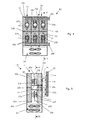
Figures 4 and 5 respectively show a schematic cross section through line IV-IV offigure 5 and a schematic cross section through line V-V offigure 4 of a preferred embodiment of the power converter arrangement. - With reference to
figures 2 through 5 , apower converter arrangement 15 has two staticswitching element bridges figures 2 and 3 schematically show in solid line an active (i.e. operating) staticswitching element bridge 16a, and in dashed line a standby (i.e. a non-operating) staticswitching element bridge 16b. Thispower converter arrangement 15 is for example a component of an exciter of an electric synchronous generator such as a turbo generator. - Each static
switching element bridge static switching elements active bridge 16a (i.e. the active static switching elements) and 17b indicates the static switching elements of thestandby bridge 17b (i.e. the standby static switching elements). - The
static switching elements - For sake of simplicity, in
figures 2 and 3 theswitching elements figures 4 and 5 the physical appearance of theswitching elements - In particular, each static
switching element bridge n switching elements ac input voltage 21. - The
power converter arrangement 15 has onehousing 18 that houses the two staticswitching element bridges housing 18 has one cooling system 19 (for example a fan unit having one or more fans in series or in parallel) for both the staticswitching element bridges - For example the
cooling system 19 includes a fan unit arranged at the bottom of thehousing 18. For redundancy reasons, thecooling system 19 may be furnished with redundant fans (e.g. infigures 4 and 5 , a 2×100% redundancy of the fans is depicted). - Since the
housing 18 houses twobridges cooling system 19 for the two staticswitching element bridges - Each static
switching element bridge branches 20, eachbranch 20 being connected to one phase of the multi-phaseac input voltage 21. In all figures, a number of three is assumed for the number of phases of the multi-phaseac input voltage 21. - With reference to
figures 4 and 5 , eachbranch 20 comprises anac bus bar 22 for receiving a phase of a multi-phaseac input voltage 21; thisbus bar 22 is connected, viaconductive rods 23a-23d provided withfuses 24 toheat sinks 25a-25d. Naturally also different configurations are possible and therods 23a-23d could not be provided, for example theac bus bar 22 could have the required shape to achieve the connection. - The heat sinks 25a-25d carry the static switching elements 17.
- In particular, two facing
heat sinks static switching elements static switching elements dc bus bar 28a inbetween. Likewise, the two facingheat sinks static switching elements static switching elements dc bus bar 28b inbetween. Thestatic switching elements dc bus bar - Advantageously, the
branches 20 of different staticswitching element bridges ac input voltage 21 have commonac bus bars 22 and commondc bus bar - a branch of the
bridge 16a connected to a phase of theac input voltage 21, and - a branch of the
bridge 16b connected to the same phase (as the above phase) of theac input voltage 21, have a common (i.e. the same)ac bus bar 22. - Similarly,
- branches of the
bridge 16a connected to a polarity of the dc output voltage, and - branches of the
bridge 16b connected to the same polarity (as the above polarity) of thedc output voltage 21,
have a common (i.e. the same)dc bus bar - The heat sinks 25a-25d (
figure 4 ) that are electrically connected to different phases of the multi-phase acinput voltage 21 are electrically insulated from each other byinsulating sheets 26a and in addition, in order to provide the protection of eachstatic switching element individual fuse 24, alsoheat sinks 25a-25d that are connected to the same phase of the multi-phase acinput voltage 21 are electrically insulated from each other byinsulating sheets 26b. - In addition, the
conductive rods heat sinks housing 18 opposite the side with theac bus bars 22, are provided withinsulating tubes 27 insulating them from theheat sinks conductive rods insulating tubes 27. - The heat sinks 25a, 25b and 25c, 25d are arranged one on top of the other and the
heat sinks - Preferably the heat sinks 25a-25d have aligned, preferably vertical,
cooling channels 30 that allow for an upwards air flow through them; thehousing 18 is permeable above theheat sinks cooling system 19 to ingest cooling air. - In particular, the heat sinks 25a, 25d and 25b, 25c, define, together with the
dc bus bars cooling channels - The
static switching elements switching element bridge static switching elements 17a and one half of thestatic switching elements 17b are located in one common cooling channel, e.g. 29a. The other half of thestatic switching elements 17a and the other half of thestatic switching elements 17b are located in the other cooling channel, e.g. 29b. With this configuration, independently of which of the staticswitching element bridges cooling channel static switching elements 17a of thebridge 16a is arranged in thechannel 29a and the other part in theother channel 29b; the same is for theother bridge 16b. - This advantageous arrangement has the benefit that the flow of cooling air on both sides of the
bus bars arrangement 15 and a better utilization of thecooling system 19. - Thanks to the advantageous arrangement of the
static switching elements static switching elements 17a are not only removed via the directlyadjacent heat sink 25a, but also via theheat sink 25c connected to the inactivestatic switching elements 17b, since the thermal resistance across thedc bus bar 28a and the inactivestatic switching element 17b is quite low (naturally the same considerations apply for thestatic switching elements heat sinks dc bus bar 28b inbetween). - Hence, all of the
heat sinks 25a-25d contribute to the cooling of the activestatic switching elements 17a, reducing the required overall mass and volume for the heat sinks considerably. - In the embodiments shown, six
static switching elements arrangement 15 are connected to thedc bus bar 28a, which is the dc output contact for one polarity, e.g. for the positive polarity, and sixstatic switching elements arrangement 15 are connected to thedc bus bar 28b, which is the dc output contact for the other polarity, e.g. for the negative polarity. - For clarity in
figures 4 and 5 the static switching elements of the active staticswitching element bridge 16a have a pattern with a narrow grid and are identified by thereference 17a, and the static switching elements of the non active (stand by) staticswitching element bridge 16b have a pattern with a large grid and are identified by thereference 17b. - For applications in three-phase ac systems (like the one shown), the
arrangement 15 has threebranches 20 for a three-phase input voltage, and two outputdc bus bars - In a preferred embodiment, the
static switching elements control unit 33. - The
control unit 33 activates or deactivates thestatic switching elements switching element bridges power converter bridges - For example, the
static switching elements figure 3 ) or IGBTs; in this case since the thyristors are selectively activable via their firing circuit and the IGBTs via gate driver circuits, the inputs of the two staticswitching element bridges ac input voltage 21. - As shown, each
static switching element fuse 24. - The response of each
fuse 24 is commonly supervised by a blown-fuse indicator. - In case a
static switching element fuse 24 automatically disconnects the failed element 17 in order to prevent further damage by high fault currents; such a failure is then indicated by a blown-fuse supervision contact. - Upon detection of a blown fuse in the active static switching element bridge, the
control unit 33 blocks the active staticswitching element bridge 16a and activates the standby staticswitching element bridge 16b. - A different embodiment of the
arrangement 15 is shown infigure 3 , in which thestatic switching elements - Also in this case the multi-phase
ac input voltage 21 of the staticswitching element bridges switching element bridges ac input voltage 21. - The operation of the
power converter arrangement 15 is apparent from that described and illustrated and is substantially the following (reference to the embodiment offigures 2 and4, 5 and static switching elements being thyristors is hereinafter made). - The
control circuit 33 drives the firing circuits of the thyristors 17 such that one staticswitching element bridge 16a is activated and the other staticswitching element bridges 16b is not activated. - The multi-phase
ac input voltage 21 supplies multi-phase ac electric power to theswitching element bridge 16a that in turn supplies dc electric power via thedc bus bars - Advantageously, since only one of the thyristors that are located at opposite sides of each
dc bus bar thyristors 17a,figure 5 ), but the other (i.e. thethyristors 17b) is in stand by and does not operate, each operatingthyristors 17a can transmit heat (for cooling) to the heat sinks on both sides, to achieve a very efficient cooling. - In addition, since each cooling
channel thyristors 17a in the example above), cooling of each thyristors is achieved with cooling air that has the lowest temperature possible; this further improves cooling. - The invention also refers to a method for operating a
power converter arrangement 15. - The method comprises:
- operating a part of the
static switching elements 17a (such as the thyristors), to define a first staticswitching element bridge 16a that converts a multi-phase ac input voltage into a dc output voltage or vice versa, and - keeping the other
static switching elements 17b (such as further thyristor) in stand-by, to define a second staticswitching element bridge 16b able to convert the multi-phase ac input voltage into a dc output voltage or vice versa and alternatively operable with respect to the first staticswitching element bridge 16a. - Naturally the features described may be independently provided from one another.
- In practice the components and materials used and the dimensions can be chosen at will according to requirements and to the state of the art.
-
- 2
- frame
- 3
- power converter device
- 4
- housing
- 5
- static switching element bridge
- 6
- multi-phase ac input
- 7
- multi-phase ac voltage supply
- 8
- dc connections
- 9
- cooling system
- 10
- switching elements
-
- 15
- power converter arrangement
- 16a
- active static switching element bridge
- 16b
- standby static switching element bridge
- 17a
- active static switching element
- 17b
- standby static switching element
- 18
- housing
- 19
- cooling system
- 20
- branch of 16a, 16b
- 21
- multi-phase ac input voltage
- 22 ac
- bus bar
- 23a-d
- conductive rod
- 24
- fuses
- 25a-d
- heat sink
- 26a,b
- insulating sheet
- 27
- insulating tube
- 28a,b
- dc bus bar
- 29a, 29b
- cooling channels
- 30
- cooling channels of 25a-d
- 33
- control unit
- 34
- switches
Claims (14)
- Power converter arrangement (15) having at least two static switching element bridges (16a, 16b), the static switching element bridges (16a, 16b) being alternatively operable and comprising static switching elements (17a, 17b), characterised in that:- the power converter arrangement (15) has one housing (18) that houses the at least two static switching element bridges (16a, 16b),- the housing (18) has one cooling system (19) for the static switching element bridges (16a, 16b) housed therein.
- Power converter arrangement (15) as claimed in claim 1, characterised in that each static switching element bridge (16a, 16b) has a plurality of branches (20), each branch (20) being connected to a phase of a multi-phase ac input voltage (21).
- Power converter arrangement (15) as claimed in claim 2, characterised in that each branch (20) of each static switching element bridge (16a, 16b):- is connected to dc bus bars (28a, 28b),- has static switching elements (17a, 17b) connected to the dc bus bars (28a, 28b),- has heat sinks (25a-25d) connected to the static switching elements (17a, 17b),- is connected to an ac bus bar (22), for receiving a phase of a multi-phase ac input voltage (21).
- Power converter arrangement (15) as claimed in claim 3, characterised in that the branches (20) of different static switching element bridges (16a, 16b) connected to the same phase of the multi-phase ac input voltage (21) have:- common ac bus bars (22),- common dc bus bars (24a, 24b).
- Power converter arrangement (15) as claimed in claim 4, characterised in that the connection of the heat sinks (25a-25d) to the respective ac bus bar (22) comprises conductive rods (23a-23d).
- Power converter arrangement (15) as claimed in claim 5, characterised in that at least some of the conductive rods (23a-23d) are provided with insulating tubes (27).
- Power converter arrangement (15) as claimed in claim 3, characterised in that the heat sinks (25a-25d) together with the dc bus bars (28a, 28b) define at least two cooling channels (29a, 29b), the static switching elements (17a, 17b) of each branch (20) of each static switching element bridge (16a, 16b) being housed in different cooling channels (29a, 29b).
- Power converter arrangement (15) as claimed in claim 1, characterised in that the heat sinks (25a-25d) have cooling channels (30), and in that the housing (18) has holes (31) aligned to the channel (30) of the heat sinks (25a-25d).
- Power converter arrangement (15) as claimed in claim 3, characterised in that an insulating sheet (26a) is provided between heat sinks (25a-25d) that are electrically connected to different phases of the multi-phase ac input voltage (21).
- Power converter arrangement (15) as claimed in claim 3, characterised in that an insulating sheet (26b) is provided between heat sinks (25a-25d) that are electrically connected to the same phase of the multi-phase ac input voltage (21).
- Power converter arrangement (15) as claimed in claim 1, characterised in that the static switching elements (17a, 17b) are controllable switches.
- Power converter arrangement (15) as claimed in claim 11, characterised in that each controllable switch is connected in series to a fuse (24).
- Power converter arrangement (15) as claimed in claim 11, characterised in that each controllable switch is connected to a drive circuit that is driven by a control unit (33), wherein the control unit (33) activates or deactivates the controllable switch constituting each of the static switching element bridges (16a, 16b) together.
- Method for operating a power converter arrangement (15) comprising:- static switching elements (17a, 17b),- one housing (18) that houses the static switching elements (17a, 17b),- one cooling system (19) for the switching elements (17a, 17b) housed in the housing (18),
the method being characterised by:- operating a part of the static switching elements (17a), to define a first static switching element bridge (16a) that converts a multi-phase ac input voltage into a dc output voltage or vice versa,- keeping at least a part of the other static switching elements (17b) in stand-by, to define a second static switching element bridge (16b) able to convert the multi-phase ac input voltage into a dc output voltage or vice versa and alternatively operable with respect to the first static switching element bridge (16a).
Priority Applications (1)
| Application Number | Priority Date | Filing Date | Title |
|---|---|---|---|
| EP12163220.2A EP2512023A3 (en) | 2011-04-14 | 2012-04-04 | Power converter arrangement and method for operating a power converter arrangement |
Applications Claiming Priority (2)
| Application Number | Priority Date | Filing Date | Title |
|---|---|---|---|
| EP11162385 | 2011-04-14 | ||
| EP12163220.2A EP2512023A3 (en) | 2011-04-14 | 2012-04-04 | Power converter arrangement and method for operating a power converter arrangement |
Publications (2)
| Publication Number | Publication Date |
|---|---|
| EP2512023A2 true EP2512023A2 (en) | 2012-10-17 |
| EP2512023A3 EP2512023A3 (en) | 2017-06-28 |
Family
ID=44508512
Family Applications (1)
| Application Number | Title | Priority Date | Filing Date |
|---|---|---|---|
| EP12163220.2A Withdrawn EP2512023A3 (en) | 2011-04-14 | 2012-04-04 | Power converter arrangement and method for operating a power converter arrangement |
Country Status (2)
| Country | Link |
|---|---|
| US (1) | US8964387B2 (en) |
| EP (1) | EP2512023A3 (en) |
Cited By (2)
| Publication number | Priority date | Publication date | Assignee | Title |
|---|---|---|---|---|
| WO2016146754A1 (en) * | 2015-03-17 | 2016-09-22 | Abb Technology Ag | Shorting device for a rectifier |
| US20200203255A1 (en) * | 2018-12-19 | 2020-06-25 | Abb Schweiz Ag | Cooling of power semiconductors |
Families Citing this family (11)
| Publication number | Priority date | Publication date | Assignee | Title |
|---|---|---|---|---|
| JP5377574B2 (en) | 2011-05-31 | 2013-12-25 | 日産自動車株式会社 | Power converter |
| JP5377575B2 (en) * | 2011-05-31 | 2013-12-25 | 日産自動車株式会社 | Power converter |
| JP5437312B2 (en) | 2011-05-31 | 2014-03-12 | 日産自動車株式会社 | Power converter |
| CN103875169B (en) * | 2011-10-07 | 2017-03-01 | 日产自动车株式会社 | power conversion device |
| US9369055B2 (en) * | 2011-10-07 | 2016-06-14 | Nissan Motor Co., Ltd. | Power converter |
| DE112015003244T5 (en) * | 2014-09-25 | 2017-04-13 | Hitachi Automotive Systems, Ltd. | power converter |
| WO2016067810A1 (en) * | 2014-10-31 | 2016-05-06 | 日立工機株式会社 | Electric work machine |
| US9490555B1 (en) * | 2015-05-22 | 2016-11-08 | Deere & Company | System or connector for voltage bus structures |
| CN106100370B (en) * | 2016-07-27 | 2017-05-10 | 中国科学院等离子体物理研究所 | A high-power and high-current aluminum alloy converter module with four-quadrant operation |
| JP6486526B1 (en) * | 2018-03-16 | 2019-03-20 | 三菱電機株式会社 | Power converter |
| JP7215194B2 (en) * | 2019-01-30 | 2023-01-31 | 富士電機株式会社 | Snubber device and power conversion device |
Family Cites Families (20)
| Publication number | Priority date | Publication date | Assignee | Title |
|---|---|---|---|---|
| US3098963A (en) * | 1958-08-25 | 1963-07-23 | Pittsburgh Plate Glass Co | Method and apparatus for controlling a direct current power source |
| US3253646A (en) * | 1964-04-08 | 1966-05-31 | Udylite Corp | Cooling system for power supply apparatus |
| US4138706A (en) * | 1977-12-01 | 1979-02-06 | General Motors Corporation | Electrical power supply fault detecting system |
| AT395793B (en) * | 1989-07-13 | 1993-03-25 | Siemens Ag Oesterreich | CIRCUIT ARRANGEMENT FOR REVERSE CONVERTERS WITH TWO COMPACT THREE-PHASE BRIDGES IN COUNTERPARALLY CIRCUIT |
| DE4237283C1 (en) * | 1992-10-31 | 1994-03-03 | Licentia Gmbh | Semiconductor power loss protecting method - waiting set time between disconnection of one of 2 anti-parallel bridge circuits in converter and switching in other bridge circuit. |
| US5453901A (en) * | 1993-10-12 | 1995-09-26 | General Electric Co. | Detection and protection of excitation system from diode failure |
| US6075717A (en) * | 1996-05-01 | 2000-06-13 | General Electric Company | PWM rectifier control with switching losses equally distributed among multiple switching devices |
| US6304443B1 (en) * | 2000-07-27 | 2001-10-16 | Shin Jiuh Corp. | Power supply equipped with extractable fan deck |
| JP3563038B2 (en) * | 2001-03-05 | 2004-09-08 | 東芝トランスポートエンジニアリング株式会社 | Power converter |
| US6603661B2 (en) * | 2001-12-14 | 2003-08-05 | Hewlett-Packard Development Company, L.P. | Universal fan cage for hot-pluggable fans |
| US6822850B2 (en) * | 2002-09-27 | 2004-11-23 | Rockwell Automation Technologies, Inc. | Laminated bus bar for use with a power conversion configuration |
| US7068507B2 (en) * | 2002-09-27 | 2006-06-27 | Rockwell Automation Technologies, Inc. | Compact liquid converter assembly |
| US6885553B2 (en) * | 2002-09-27 | 2005-04-26 | Rockwell Automation Technologies, Inc. | Bus bar assembly for use with a compact power conversion assembly |
| US6721181B1 (en) * | 2002-09-27 | 2004-04-13 | Rockwell Automation Technologies, Inc. | Elongated heat sink for use in converter assemblies |
| CN2572462Y (en) * | 2002-09-28 | 2003-09-10 | 王万源 | Fault-tolerant power source module set for PC mainframe |
| US6998735B2 (en) * | 2002-10-28 | 2006-02-14 | Eaton Corporation | Controlled rectifier bridge, control system, and method for controlling rectifier bridge by disabling gate control signals |
| JP4848209B2 (en) * | 2006-05-31 | 2011-12-28 | 株式会社日立産機システム | Power converter |
| WO2009027520A2 (en) * | 2007-08-31 | 2009-03-05 | Vestas Wind Systems A/S | Modular converter system with interchangeable converter modules |
| JP4580997B2 (en) * | 2008-03-11 | 2010-11-17 | 日立オートモティブシステムズ株式会社 | Power converter |
| EP2648495B1 (en) * | 2012-04-04 | 2015-02-25 | Inmotion Technologies AB | Switched power converter |
-
2012
- 2012-04-04 EP EP12163220.2A patent/EP2512023A3/en not_active Withdrawn
- 2012-04-13 US US13/446,872 patent/US8964387B2/en not_active Expired - Fee Related
Non-Patent Citations (1)
| Title |
|---|
| None |
Cited By (3)
| Publication number | Priority date | Publication date | Assignee | Title |
|---|---|---|---|---|
| WO2016146754A1 (en) * | 2015-03-17 | 2016-09-22 | Abb Technology Ag | Shorting device for a rectifier |
| US20200203255A1 (en) * | 2018-12-19 | 2020-06-25 | Abb Schweiz Ag | Cooling of power semiconductors |
| US12107032B2 (en) * | 2018-12-19 | 2024-10-01 | Abb Schweiz Ag | Cooling of power semiconductors |
Also Published As
| Publication number | Publication date |
|---|---|
| EP2512023A3 (en) | 2017-06-28 |
| US8964387B2 (en) | 2015-02-24 |
| US20120262884A1 (en) | 2012-10-18 |
Similar Documents
| Publication | Publication Date | Title |
|---|---|---|
| US8964387B2 (en) | Power converter arrangement and method for operating a power converter arrangement | |
| US11177648B2 (en) | System and method for compact motor control with redundant power structures | |
| US8830658B2 (en) | Switchgear cabinet arrangement of a device for producing electric energy | |
| JP5584357B2 (en) | Variable speed drive | |
| US11563385B2 (en) | DC chopper for MMC cell with integrated chopper resistor | |
| CN101411050A (en) | Power converter and its assembling method | |
| CN102545647A (en) | Ac-to-ac converter and method for converting a first frequency ac-voltage to a second frequency ac-voltage | |
| WO2015090428A1 (en) | Method and system for handling converter cell failure | |
| CN101290931B (en) | A high-power self-cooling thyristor valve and its installation vehicle | |
| US11063527B2 (en) | Converter | |
| WO2013139373A1 (en) | Switch module and associated method | |
| CN103503316A (en) | Power module and method of operating a power module | |
| US11910554B2 (en) | Modular and pluggable PDU to power tray/shelf device | |
| WO1998042066A1 (en) | High power inverter pole employing series connected devices configured for reduced stray loop inductance | |
| WO2016026514A1 (en) | Power converter and assembly method for assembling a power converter | |
| CN105305907A (en) | Novel high-power generator excitation device | |
| CN111164746A (en) | Semiconductor assembly with fault protection | |
| CN106463949B (en) | Circuit breaker is arranged | |
| Wahlstroem et al. | High power IGCT based multilevel inverter | |
| Rocha et al. | A thermal management approach to fault-resilient design of three-level IGCT-based NPC converters | |
| WO2016058639A1 (en) | Power converter circuit | |
| KR100833569B1 (en) | IPT stack device with evenly distributed parallel structure for large capacity power converter | |
| Cordeiro et al. | Fault-tolerant design of three-phase dual-buck VSI topologies | |
| WO2018177732A1 (en) | 3-level power module | |
| CN218868124U (en) | Power converter device with support structure |
Legal Events
| Date | Code | Title | Description |
|---|---|---|---|
| PUAI | Public reference made under article 153(3) epc to a published international application that has entered the european phase |
Free format text: ORIGINAL CODE: 0009012 |
|
| AK | Designated contracting states |
Kind code of ref document: A2 Designated state(s): AL AT BE BG CH CY CZ DE DK EE ES FI FR GB GR HR HU IE IS IT LI LT LU LV MC MK MT NL NO PL PT RO RS SE SI SK SM TR |
|
| AX | Request for extension of the european patent |
Extension state: BA ME |
|
| RAP1 | Party data changed (applicant data changed or rights of an application transferred) |
Owner name: GENERAL ELECTRIC TECHNOLOGY GMBH |
|
| PUAL | Search report despatched |
Free format text: ORIGINAL CODE: 0009013 |
|
| AK | Designated contracting states |
Kind code of ref document: A3 Designated state(s): AL AT BE BG CH CY CZ DE DK EE ES FI FR GB GR HR HU IE IS IT LI LT LU LV MC MK MT NL NO PL PT RO RS SE SI SK SM TR |
|
| AX | Request for extension of the european patent |
Extension state: BA ME |
|
| RIC1 | Information provided on ipc code assigned before grant |
Ipc: H02M 7/757 20060101ALI20170523BHEP Ipc: H02M 7/06 20060101ALI20170523BHEP Ipc: H02M 7/162 20060101ALI20170523BHEP Ipc: H02M 7/219 20060101ALI20170523BHEP Ipc: H02M 7/00 20060101AFI20170523BHEP Ipc: H02H 7/06 20060101ALI20170523BHEP Ipc: H02M 7/797 20060101ALI20170523BHEP |
|
| 17P | Request for examination filed |
Effective date: 20180102 |
|
| RBV | Designated contracting states (corrected) |
Designated state(s): AL AT BE BG CH CY CZ DE DK EE ES FI FR GB GR HR HU IE IS IT LI LT LU LV MC MK MT NL NO PL PT RO RS SE SI SK SM TR |
|
| GRAP | Despatch of communication of intention to grant a patent |
Free format text: ORIGINAL CODE: EPIDOSNIGR1 |
|
| RIC1 | Information provided on ipc code assigned before grant |
Ipc: H02M 7/797 20060101ALI20190131BHEP Ipc: H02M 7/162 20060101ALI20190131BHEP Ipc: H02M 7/219 20060101ALI20190131BHEP Ipc: H02M 7/00 20060101AFI20190131BHEP Ipc: H02M 7/06 20060101ALI20190131BHEP Ipc: H02H 7/06 20060101ALI20190131BHEP Ipc: H05K 7/20 20060101ALI20190131BHEP Ipc: H02M 7/757 20060101ALI20190131BHEP |
|
| INTG | Intention to grant announced |
Effective date: 20190222 |
|
| STAA | Information on the status of an ep patent application or granted ep patent |
Free format text: STATUS: THE APPLICATION IS DEEMED TO BE WITHDRAWN |
|
| 18D | Application deemed to be withdrawn |
Effective date: 20190705 |