EP2511654A1 - Three-dimensional scanner and robot system - Google Patents
Three-dimensional scanner and robot system Download PDFInfo
- Publication number
- EP2511654A1 EP2511654A1 EP12157489A EP12157489A EP2511654A1 EP 2511654 A1 EP2511654 A1 EP 2511654A1 EP 12157489 A EP12157489 A EP 12157489A EP 12157489 A EP12157489 A EP 12157489A EP 2511654 A1 EP2511654 A1 EP 2511654A1
- Authority
- EP
- European Patent Office
- Prior art keywords
- scanning
- image
- unit
- region
- light beam
- Prior art date
- Legal status (The legal status is an assumption and is not a legal conclusion. Google has not performed a legal analysis and makes no representation as to the accuracy of the status listed.)
- Granted
Links
Images



Classifications
-
- G—PHYSICS
- G01—MEASURING; TESTING
- G01B—MEASURING LENGTH, THICKNESS OR SIMILAR LINEAR DIMENSIONS; MEASURING ANGLES; MEASURING AREAS; MEASURING IRREGULARITIES OF SURFACES OR CONTOURS
- G01B11/00—Measuring arrangements characterised by the use of optical techniques
- G01B11/24—Measuring arrangements characterised by the use of optical techniques for measuring contours or curvatures
- G01B11/25—Measuring arrangements characterised by the use of optical techniques for measuring contours or curvatures by projecting a pattern, e.g. one or more lines, moiré fringes on the object
- G01B11/2518—Projection by scanning of the object
-
- G—PHYSICS
- G01—MEASURING; TESTING
- G01B—MEASURING LENGTH, THICKNESS OR SIMILAR LINEAR DIMENSIONS; MEASURING ANGLES; MEASURING AREAS; MEASURING IRREGULARITIES OF SURFACES OR CONTOURS
- G01B11/00—Measuring arrangements characterised by the use of optical techniques
- G01B11/24—Measuring arrangements characterised by the use of optical techniques for measuring contours or curvatures
- G01B11/25—Measuring arrangements characterised by the use of optical techniques for measuring contours or curvatures by projecting a pattern, e.g. one or more lines, moiré fringes on the object
Definitions
- the embodiments discussed herein are directed to a three-dimensional scanner and a robot system.
- This three-dimensional scanner that measures a three-dimensional shape of an object (for example, see Japanese Patent Laid-open Publication No. H07-270137 ).
- This three-dimensional scanner for example, emits a slit-shaped light beam to a measuring object while changing an irradiation position with respect to the measuring object and sequentially captures images of the measuring object irradiated with the light beam by a camera.
- the three-dimensional scanner detects the position of the light beam in an image by reading out image information on the captured image from photodetectors of the camera and scanning all pixels of the captured image.
- the three-dimensional scanner measures the three-dimensional shape of the measuring object by calculating the height of each portion of the measuring object by the principle of triangulation using an irradiation angle and an acceptance angle of the light beam and the distance from a light source of the light beam to the camera.
- An aspect of embodiments is achieved in view of the above and has an object to provide a three-dimensional scanner and a robot system capable of accelerating a measuring process of a three-dimensional shape.
- a three-dimensional scanner includes an irradiation unit, an imaging unit, a position detecting unit, and a scanning-region determining unit.
- the irradiation unit emits a slit-shaped light beam while changing an irradiation position with respect to a measuring object.
- the imaging unit sequentially captures images of the measuring object irradiated with the light beam.
- the position detecting unit detects a position of the light beam in an image captured by the imaging unit by scanning the image.
- the scanning-region determining unit determines a scanning region in an image as a scanning target by the position detecting unit based on a position of the light beam in an image captured by the imaging unit before the image as a scanning target.
- FIG. 1A is a diagram illustrating a positional relationship between a three-dimensional scanner and a measuring object according to a first embodiment
- FIG. 1B to FIG. 1C are diagrams illustrating an example of an image captured by an imaging unit of the three-dimensional scanner according to the first embodiment
- FIG. 2 is a block diagram illustrating the configuration of the three-dimensional scanner according to the first embodiment
- FIG. 3 is a diagram illustrating a measuring method of a three-dimensional according to the first embodiment
- FIG. 4A to FIG. 4C are diagrams illustrating a determination example of a scanning region and a detection example of a laser position according to the first embodiment
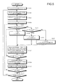
- FIG. 5 is a flowchart illustrating a process performed by a control unit according to the first embodiment
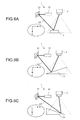
- FIG. 6A to FIG. 6C and FIG. 7A to FIG. 7C are explanatory diagrams of a correcting method of a scanning region by a scanning-region determining unit according to the first embodiment.
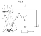
- FIG. 8 is a diagram illustrating a robot system according to a second embodiment.
- FIG. 1A is a diagram illustrating a positional relationship between a three-dimensional scanner 1 and a measuring object 7 according to the first embodiment
- FIG. 1B to FIG. 1C are diagrams illustrating an example of an image captured by an imaging unit 3 of the three-dimensional scanner 1 according to the first embodiment.
- an XY coordinate system as a Cartesian coordinate system is provided on a placement surface on which the measuring object 7 is placed and a vertically-downward direction from the placement surface is defined as a Z axis for easy understanding of the explanation.
- explanation is made for a case where a rectangular parallelepiped to be placed on a stage 6 to be the placement surface of the measuring object 7 is the measuring object 7 and the three-dimensional shape of the measuring object 7 is measured by the three-dimensional scanner 1 from the vertically-upward direction.
- the three-dimensional scanner 1 emits a slit-shaped light beam (hereinafter, described as "laser LA") toward a mirror 22 from a laser device 21.
- laser LA a slit-shaped light beam
- the three-dimensional scanner 1 emits the laser LA to the measuring object 7 while changing an irradiation position with respect to the measuring object 7 by rotating the mirror 22.
- the three-dimensional scanner 1 emits the laser LA from a diagonally-upward direction with respect to the measuring object 7 while moving the irradiation position of the laser LA on the measuring object 7 toward a positive direction from a negative direction of the X axis.
- the three-dimensional scanner 1 sequentially captures images of the measuring object 7, which is irradiated with the laser LA, by the imaging unit 3. That is, the imaging unit 3 images the laser LA moving on the stage 6 and the measuring object 7 in a moving direction for each imaging flame by receiving the laser LA reflected by the stage 6 and the measuring object 7.
- the three-dimensional scanner 1 detects the position (hereinafter, described as "laser position") of the laser LA in each image captured by the imaging unit 3 and measures the three-dimensional shape of the measuring object 7 by the principle of triangulation using the detected laser positions.
- the three-dimensional scanner 1 detects a laser position La in the image by scanning the image with the whole image as a scanning region SA as shown in FIG. 1B .
- the three-dimensional scanner 1 scans all pixels of the first image while sequentially moving a scanning start position in each scanning in a scanning direction, which is a direction parallel to the positive direction of the X axis, in a direction parallel to a positive direction of the Y axis.
- the imaging unit 3 includes a plurality of photodetectors arrayed on a light receiving surface, and the arrangement posture of the imaging unit 3 is adjusted in advance so that the array direction (in this example, X-axis direction) of the photodetectors matches the moving direction of the laser LA.
- the three-dimensional scanner 1 reads out information on luminance of each pixel in an image from all photodetectors included in the imaging unit 3 and compares luminance of each pixel with a predetermined threshold for each pixel line arrayed in the scanning direction.
- the three-dimensional scanner 1 detects the position of the brightest pixel among pixels, whose luminance exceeds a predetermined threshold in each pixel line, as the position La of the laser LA in the first image. It is possible to obtain a luminance profile of pixels, whose luminance exceeds a predetermined threshold, and calculates the laser position La with sub-pixel accuracy by a center-of-gravity calculation process.
- the three-dimensional scanner 1 detects a laser position Lb in the second image by selectively reading out information on luminance of each pixel from photodetectors corresponding to a scanning region SB narrower than the case of scanning the first image and scanning pixels in the scanning region SB.
- the laser LA is moved on the stage 6 and the measuring object 7 in the positive direction of the X axis. Therefore, the laser position Lb in the second image is detected on the positive side of the X axis with respect to the laser position La in the first image. In other words, the laser position Lb in the second image is not detected on the negative side of the X axis with respect to the laser position La in the first image.
- the laser position La in the first image is determined as a scanning start position and the position, which is away from the scanning start position in the scanning direction by a predetermined distance determined based on the estimated moving distance of the laser LA, is determined as a scanning end position.
- the laser position Lb in the second image can be detected by selectively reading out information on luminance of pixels from photodetectors smaller in number than the case of scanning the first image and scanning each pixel.
- the time required for a process of reading out information on luminance of pixels from the imaging unit 3 and a detecting process of a laser position in an image can be shortened, so that a measuring process of a three-dimensional shape can be accelerated.
- a scanning region for detecting a laser position can be appropriately limited and determined, when ambient light or the like enters a region outside the determined scanning region, the ambient light or the like is not falsely detected as the laser LA.
- a scanning region in the third image is determined based on the laser position La in the first image and the laser position Lb in the second image. This point will be described later with reference to FIG. 4C .
- FIG. 2 is a block diagram illustrating the configuration of the three-dimensional scanner 1 according to the first embodiment.
- the three-dimensional scanner 1 includes an irradiation unit 2, the imaging unit 3, a control unit 4, and a storage unit 5.
- the irradiation unit 2 is a device that emits the laser LA while changing an irradiation position with respect to the stage 6 and the measuring object 7 according to control by the control unit 4.
- the irradiation unit 2 includes the laser device 21 and the mirror 22.
- the laser device 21 is a device that emits the laser LA as a slit-shaped light beam to the reflecting surface of the mirror 22 based on a control signal input from the control unit 4.
- the mirror 22 is a reflective plate that emits the laser LA emitted from the laser device 21 so that an irradiation position on the stage 6 and the measuring object 7 moves from the negative direction to the positive direction of the X axis, by controlling rotation of the reflecting surface based on the control signal input from the control unit 4.
- the imaging unit 3 is a camera including a CMOS (Complementary Metal Oxide Semiconductor) sensor as photodetectors.
- CMOS Complementary Metal Oxide Semiconductor
- the imaging unit 3 sequentially captures images of the stage 6 and the measuring object 7 irradiated with the laser LA, and outputs the captured images to the control unit 4.
- any image sensor such as a CCD (Charge Coupled Device) sensor, can be applied instead of a CMOS sensor.
- the storage unit 5 is a storage device that stores image information 51, laser position information 52, shape information 53, and the like.
- the image information 51 is information indicating an image captured by the imaging unit 3 and the laser position information 52 is information indicating a laser position in each image captured by the imaging unit 3.
- the shape information 53 is information indicating the three-dimensional shape of the measuring object 7 measured by the three-dimensional scanner 1.
- the control unit 4 is a processing unit that collectively controls the operation of the whole three-dimensional scanner 1 and includes an image-information obtaining unit 41, a position detecting unit 42, a scanning-region determining unit 43, a shape measuring unit 44, and an irradiation control unit 45.
- the irradiation control unit 45 is a processing unit that outputs a control signal instructing emission of the laser LA to the laser device 21 and outputs a control signal instructing the rotation angle of the reflecting surface to the mirror 22. Moreover, the irradiation control unit 45 outputs information indicating the rotation angle of the mirror 22 to the shape measuring unit 44.
- the image-information obtaining unit 41 is a processing unit that obtains images sequentially captured by the imaging unit 3 from the imaging unit 3 and stores them in the storage unit 5 as the image information 51.
- the image-information obtaining unit 41 selectively reads out and obtains information on luminance of pixels from photodetectors corresponding to a scanning region input from the scanning region determining unit 43 among all 1 photodetectors of the imaging unit 3, as the image information 51.
- the position detecting unit 42 is a processing unit that detects a laser position in each of images sequentially captured by the imaging unit 3 based on the image information 51 read out from the storage unit 5.
- the position detecting unit 42 scans pixels in a scanning region determined by the scanning-region determining unit 43.
- the position detecting unit 42 detects the position of the brightest pixel in an image among pixels, whose luminance exceeds a predetermined threshold among scanned pixels, as a laser position in each image and outputs a detection result to the shape measuring unit 44, and stores the detection result in the storage unit 5 as the laser position information 52.
- a detection example of a laser position by the position detecting unit 42 is described later with reference to FIG. 4A, FIG. 4B, and FIG. 4C .
- the scanning region determining unit 43 is a processing unit that determines a scanning region in an image as a scanning target by using a laser position in an image captured by the imaging unit 3 before the image as a scanning target by the position detecting unit 42 based on the laser position information 52 read out from the storage unit 5.
- the scanning region determining unit 43 determines each scanning region for each pixel line (hereinafter, described as "line") to be scanned in the scanning direction by the position detecting unit 42 for each image and outputs information indicating the determined scanning region to the image-information obtaining unit 41.
- line a scanning region by the scanning region determining unit 43 will be described later with reference to FIG. 4A, FIG. 4B, and FIG. 4C .
- the scanning region determining unit 43 corrects a scanning region according to a distance (hereinafter, described as "height of the measuring object 7") in a normal direction in an image of the measuring object 7 based on the shape information 53 read out from the storage unit 5. This point will be described later with reference to FIG. 6A, FIG. 6B, FIG. 6C , FIG. 7A, FIG. 7B, and FIG. 7C .
- the shape measuring unit 44 is a processing unit that measures the three-dimensional shape of the measuring object 7 by the principle of triangulation based on a laser position in each image input from the position detecting unit 42 and the rotation angle of the mirror 22 input from the irradiation control unit 45.
- the shape measuring unit 44 stores the measured three-dimensional shape of the measuring object 7 in the storage unit 5 as the shape information 53.
- FIG. 3 is a diagram illustrating a measuring method of a three-dimensional shape according to the first embodiment.
- the mirror 22 and the imaging unit 3 are arranged so that a reflecting position 23 of the laser LA in the mirror 22 and a light receiving position 31 of the laser LA in the imaging unit 3 are positioned on the same plane (hereinafter, described as "reference plane Zl") parallel to the stage 6.
- the shape measuring unit 44 calculates an irradiation angle a of the laser LA with respect to the measuring object 7 based on the rotation angle of the mirror 22. Furthermore, the shape measuring unit 44 calculates an acceptance angle b of the laser LA by the imaging unit 3 based on a laser position in an image.
- a distance c from the reflecting position 23 of the laser LA in the mirror 22 to the light receiving position 31 of the laser LA in the imaging unit 3 is known, and a distance d from the reference plane Z1 to the stage 6 is also known.
- the shape measuring unit 44 can calculate a distance e from the reference plane Z1 to the top surface of the measuring object 7 by the principle of triangulation using the distance c from the reflecting position 23 of the laser LA in the mirror 22 to the light receiving position 31 of the laser LA in the imaging unit 3, and the irradiation angle a and the acceptance angle b of the laser LA.
- the shape measuring unit 44 can calculate a height f of the measuring object 7 by subtracting the distance e from the reference plane Z1 to the top surface of the measuring object 7 from the distance d from the reference plane Z1 to the stage 6. Therefore, the shape measuring unit 44 can calculate the three-dimensional shape of the measuring object 7 by calculating the height f for each portion of the measuring object 7.
- FIG. 4A, FIG. 4B, and FIG. 4C are diagrams illustrating a determination example of a scanning region and a detection example of a laser position according to the first embodiment.
- an image as a scanning target is an n-th image captured by the imaging unit 3 and is a first image relating to the measuring object 7.
- the scanning-region determining unit 43 determines all pixels on a line (hereinafter, described as "zeroth line"), on which pixels are aligned in the X axis direction on the most negative side in the Y axis direction in the image, as a scanning region Sa of the zeroth line.
- the position detecting unit 42 scans all pixels in the scanning region Sa in the positive direction of the X axis, compares the luminance of each pixel with a predetermined threshold, and detects a position P of the brightest pixel among pixels, whose luminance exceeds the predetermined threshold, as a laser position P on the zeroth line. When there is no pixel whose luminance exceeds the predetermined threshold, it is determined that laser is not detected.
- the scanning-region determining unit 43 determines the scanning region Sa for all lines in the n-th image in the similar manner and the position detecting unit 42 detects the laser position P for all lines in the similar manner. That is, in the n-th image, all pixels included in the image are determined as the scanning region Sa by the scanning-region determining unit 43 and all pixels included in the image are scanned by the position detecting unit 42.
- an image as a scanning target is an (n+1)th image captured by the imaging unit 3 and is a second image relating to the measuring object 7.
- the scanning-region determining unit 43 determines a scanning region in the image (in this example, (n+1)th image) as a scanning target captured this time based on a one-frame preceding image (in this example, n-th image) that is an image captured last time.
- the scanning-region determining unit 43 determines a laser position P 1 [0] in the n-th image as a scanning start position in the image as a scanning target.
- the scanning-region determining unit 43 determines a position, which is away from the determined scanning start position by a predetermined distance WIDTH1 in the positive direction of the X axis that is the scanning direction, as a scanning end position and determines a region from the scanning start position to the scanning end position as the scanning region Sb in the zeroth line.
- the predetermined distance WIDTH1 is, for example, determined by estimating a moving distance of the laser LA moving on the measuring object 7 until the (n+1)th image is captured after the n-th image is captured, based on the rotation speed of the mirror 22 and multiplying the estimated moving distance by a predetermined factor.
- the image-information obtaining unit 41 selectively reads out the image information 51 on luminance of each pixel in the scanning region Sb from photodetectors corresponding to the scanning region Sb and stores it in the storage unit 5. Moreover, the position detecting unit 42 scans the pixels in the scanning region Sb in the positive direction of the X axis based on the image information 51, compares the luminance of each pixel with a predetermined threshold, and detects the position P of the brightest pixel among pixels, whose luminance exceeds the predetermined threshold, as the laser position P on the zeroth line.
- the scanning-region determining unit 43 determines the scanning region Sb for each line in the (n+1)th image in the similar manner and the position detecting unit 42 detects the laser position P by scanning the pixels in the scanning region Sb on each line.
- the scanning-region determining unit 43 determines the scanning region Sb in the (n+1)th image by selecting a region in which a laser position is highly likely to be detected.
- the position detecting unit 42 becomes capable of detecting the laser position P based on the image information 51 selectively obtained from photodetectors corresponding to the scanning region Sb by the image-information obtaining unit 41, so that the laser position P can be detected in the processing time shorter than the case of detecting the laser position p by scanning all pixels of an image.
- the processing time required for a process of reading out the image information 51 from photodetectors and detecting the laser position p in an image can be shortened, enabling to accelerate the measuring process of a three-dimensional shape.
- an image as a scanning target is an (n+2)th image captured by the imaging unit 3 and is a third image relating to the measuring object 7.
- the scanning-region determining unit 43 determines a scanning region Sc in an image (in this embodiment, (n+2)th image) as a scanning target captured this time based on a one-frame-preceding image (in this embodiment, (n+1)th image), which is an image captured last time, and a two-frame-preceding image (in this embodiment, n-th image), which is an image captured immediately before the last time.
- the scanning-region determining unit 43 first determines the laser position P 1 [0] in the (n+1)th image as a scanning start position P 1 [0] in the image as a scanning target.
- the scanning-region determining unit 43 determines a position, which is away from the scanning start position P 1 [0] by the distance P 1 [0] - P 2 [0] + predetermined margin WIDTH2 in the positive direction of the X axis, as a scanning end position, thereby determining the scanning region Sc.
- WIDTH2 may be variable depending on the rotation speed of the mirror in the similar manner to WIDTH1.
- the scanning-region determining unit 43 can appropriately determine the scanning region Sc narrower than the scanning region Sb shown in FIG. 4B based on a rough prediction by using actual laser positions in an one-frame-preceding image and a two-frame-preceding image.
- the image-information obtaining unit 41 selectively reads out the image information 51 on luminance of each pixel in the scanning region Sc from photodetectors corresponding to the scanning region Sc and stores it in the storage unit 5.
- the position detecting unit 42 scans the pixels in the scanning region Sc in the positive direction of the X axis, compares the luminance of each pixel with a predetermined threshold, and detects the position P of the brightest pixel among pixels, whose luminance exceeds the predetermined threshold, as a laser position on the zeroth line.
- the scanning-region determining unit 43 determines the scanning region Sc for each line in the (n+2)th image in the similar manner and the position detecting unit 42 detects the laser position P by scanning the pixels in the scanning region Sc of each line.
- the position detecting unit 42 can detect the laser position P in the (n+2)th image by scanning the pixels of the scanning region Sc further narrower than the scanning region Sb in the (n+1)th image.
- the processing time required for a process of reading out the image information 51 from photodetectors and a process of detecting the laser position P in an image can be further shortened, so that the measuring process of a three-dimensional shape can be further accelerated.
- the scanning-region determining unit 43 determines a scanning region in an image as a scanning target based on laser positions actually detected from an image captured last time and an image captured immediately before the last time in the similar manner to the case of the (n+2)th image. Moreover, the position detecting unit 42 detects a laser position in the (n+3)th and subsequent images in the similar manner to the case of the (n+2)th image.
- a scanning region in the (n+3)th and subsequent images may be determined based on a rate of change of a difference in a laser position between two continuously-captured images.
- the difference in a laser position between two continuous images is sequentially calculated based on the shape information 53 and the difference is stored in the storage unit 5 in a time sequence.
- the scanning-region determining unit 43 determines a scanning region in an image as a scanning target in consideration of the rate of change.
- the scanning-region determining unit 43 first determines a laser position of a one-frame preceding image as a scanning start position.
- the scanning-region determining unit 43 determines a position, which is away from the scanning start position by a distance, which is shorter than the difference in a laser position between the one-frame preceding image and a two-frame preceding image, in the scanning direction, as a scanning end position in consideration of the above-described decreasing rate of the difference.
- the margin WIDTH2 may be added to the determined scanning region.
- the three-dimensional scanner 1 can narrow a scanning region more appropriately, so that the processing time required for detecting a laser position of an image can be further shortened, enabling to further accelerate the measuring process of a three-dimenszonal shape.
- FIG. 5 is a flowchart illustrating the process performed by the control unit 4 according to the first embodiment.
- MEASURE shown in FIG. 5 is the number of images obtained by imaging the measuring object 7 by the imaging unit 3 and LINE is the number of lines in an image.
- [LINE] is a laser position in an image, which is one frame before an image as a scanning target
- P 2 [LINE] is a laser position in an image, which is two frames before an image as a scanning target.
- L 1 is a scanning start position in each line and L 2 is a scanning end position in each line.
- WIDTH1 in FIG. 5 corresponds to WIDTH1 shown in FIG. 4B and WIDTH2 in FIG. 5 corresponds to WIDTH2 shown in FIG. 4C .
- the control unit 4 first assigns 0 to a predetermined variable t (Step S101) and captures a t-th image by causing the imaging unit 3 to start imaging exposure of the t-th image (Step S102).
- the variable t represents an order of capturing an image as a scanning target.
- control unit 4 initializes P 1 [LINE] and P 2 [LINE] by assigning 0 to each LINE of P 1 [LINE] and P 2 [LINE] (Step S103).
- control unit 4 assigns 0 to a predetermined variable n (Step S104).
- the variable n represents an order of a line as a scanning target.
- Step S105 when the control unit 4 determines that the laser LA is not detected (Yes at Step S105), the control unit 4 assigns 0 to L 1 and LINE-1 to L 2 (Step S106), and moves the process to Step S107. That is, when the laser LA is not detected in the n-th line of a one-frame preceding image, the control unit 4 determines all pixels in the n-th line as the scanning region Sa (see FIG. 4A ) and moves the process to Step S107.
- Step S113 the control unit 4 determines whether the laser LA is not detected in the n-th line of a two-frame preceding image.
- Step S113 when the control unit 4 determines that the laser LA is not detected (Yes at Step S113), the control unit 4 assigns P 1 [n] to L 1 and L 1 +WIDTH1 to L 2 (Step S114), and moves the process to Step S107. That is, the control unit 4 determines the scanning region Sb (see FIG. 4B ) with a laser position in a one-frame preceding image as a scanning start position and a position away from the scanning start position by WIDTH1 in the positive direction of the X axis as a scanning end position, and moves the process to Step S107.
- control unit 4 determines that the laser LA has been detected in the n-th line of a two-frame preceding image, (No at Step S113), the control unit 4 assigns P 1 [n] to L 1 and L 1 +P 1 [n]-P 2 [n]+WIDTH2 to L 2 (Step S115) and moves the process to Step S107.
- Step S115 the control unit 4 determines the scanning region Sc (see FIG. 4C ) with a laser position in a one-frame preceding image as a scanning start position and a position away from the scanning start position by P 1 [n]-P 2 [n]+WIDTH2 in the positive direction of the X axis as a scanning end position and moves the process to Step S107.
- Step S107 the control unit 4 detects a laser position by reading out and obtaining the image information 51 from L 1 to L 2 on the n line (n-th line) from photodetectors of the imaging unit 3 and calculating the laser position P from the obtained image information 51, and moves the process to Step S108.
- the control unit 4 assigns 0 to P and moves the process to Step S108.
- Step S108 determines whether P ⁇ 0 or L 1 ⁇ 0. That is, the control unit 4 determines whether a laser position can be detected or whether all pixels in the n-th line are scanned. Then, when a laser position cannot be detected and scanning is not performed on all pixels in the n-th line (No at Step S108), the control unit 4 moves the process to Step S106 and scans all pixels in the n-th line again and detects a laser position.
- Step S108 when a laser position can be detected (Yes at Step S108), the control unit 4 performs a three-dimensional calculation process (Step S109) and stores a calculation result in the storage unit 5 as the shape information 53 (Step S110). Next, after incrementing the variable n by one (not shown), the control unit 4 determines whether the variable n is equal to or more than LINE (Step S111).
- Step S105 the control unit 4 repeats the processes at Step S105 to Step S111 and Step S113 to Step S115 until completing scanning of all lines in one image.
- Step S111 when the control unit 4 determines that the variable n reaches LINE (Yes at Step S111), after incrementing the variable t by one (not shown), the control unit 4 determines whether the variable t is equal to or more than MEASURE (Step S112).
- Step S112 When the control unit 4 determines that the variable t is less than MEASURE (No at Step S112), the control unit 4 moves the process to Step S102. That is, the control unit 4 repeats the processes at Step S102 to Step S115 until completing scanning of images of all frames. On the other hand, when the control unit 4 determines that the variable t reaches MEASURE (Yes at Step S112), the control unit 4 ends the process.
- FIG. 6A, FIG. 6B, FIG. 6C , FIG. 7A, FIG. 7B, and FIG. 7C are explanatory diagrams of a correcting method of a scanning region by the scanning-region determining unit 43.
- FIG. 6A, FIG. 6B, FIG. 6C , FIG. 7A, FIG. 7B, and FIG. 7C the components same as those shown in FIG. 3 are denoted by the same reference numerals. Moreover, in the followings, a case where the rotation speed of the mirror 22 is constant and the time interval of imaging by the imaging unit 3 is constant is explained.
- the scanning-region determining unit 43 determines the laser position P 1 [0] in a one-frame preceding image as a scanning start position in an image as a scanning target. Then, the scanning-region determining unit 43 determines the position P away from the scanning start position by the predetermined distance WIDTH1 in the positive direction of the X axis as a scanning end position.
- a distance q between the laser position P 1 [0] in a one-frame preceding image and the laser position P in an image as a scanning target becomes shorter than a distance p shown in FIG. 7A .
- the scanning-region determining unit 43 determines whether an object is the measuring object 71, whose height in the Z-axis direction becomes higher toward the positive direction of the X axis, based on the shape information 53 on a portion, whose shape has been measured, among the portions of the measuring object 71.
- the scanning-region determining unit 43 performs correction of determining a region from the laser position P 1 [0] in a one-frame preceding image to a position away from the laser position P 1 [0] by a distance WIDTH1a, which is shorter than the predetermined distance WIDTH1 in the positive direction of the X axis, as a scanning region.
- a distance r between the laser position P 1 [0] in a one-frame preceding image and the laser position P in an image as a scanning target becomes longer than the distance p shown in FIG. 7A .
- the scanning-region determining unit 43 determines whether an object is the measuring object 72, whose height in the Z-axis direction becomes smaller toward the positive direction of the X axis, based on the shape information 53 on a portion, whose shape has been measured, among the portions of the measuring object 72.
- the scanning-region determining unit 43 performs correction of determining a region from the laser position P 1 [0] in a one-frame preceding image to a position away from the laser position P 1 [0] by a distance WIDTH1b, which is longer than the predetermined distance WIDTH1 in the positive direction of the X axis, as a scanning region.
- the position detecting unit 42 can detect the laser position P in an image without scanning unnecessary pixels. Therefore, in the three-dimensional scanner 1, the measuring process of a three-dimensional shape can be accelerated by appropriately shortening the processing time required for the detecting process of the laser position P.
- the scanning-region determining unit 43 may be configured to correct a scanning region even when the height of each portion in the measuring object 7 is the same. For example, when the length of the measuring object 7 in the X-axis direction exceeds a predetermined length, the moving speed of the laser LA becomes high as an irradiation position of the laser LA on the measuring object 7 moves in the positive direction of the X axis, which cannot be ignored in some cases.
- the scanning-region determining unit 43 performs correction of extending a scanning region in the scanning direction as an irradiation position of laser on the measuring object 7 moves in the positive direction of the X-axis. With this correction, even when the length of the measuring object 7 in the X-axis direction exceeds a predetermined length, an appropriate scanning region can be determined, so that a laser position in an image can be appropriately detected.
- FIG. 8 is a diagram illustrating a robot system 10 according to the embodiment.
- the robot system 10 that causes a robot to identify workpieces piled up in bulk and perform a work using the identified workpieces.
- screws are illustrated as an example of the workpieces, however, the workpieces are not limited to screws and may be any member such as bolts and nuts.
- the robot system 10 includes the three-dimensional scanner 1, a robot control apparatus 11, and a robot 12.
- the three-dimensional scanner 1 is similar to that explained in the first embodiment and is arranged vertically above the stacked workpieces and measures the three-dimensional shape of the workpieces.
- the robot control apparatus 11 is connected to the three-dimensional scanner 1 and the robot 12 and obtains the shape information 53 (see FIG. 2 ) on the workpieces piled up in bulk from the three-dimensional scanner 1. Next, the robot control apparatus 11 determines the position and the orientation of a workpiece as a work target from the workpieces piled in bulk and outputs a determination result to the robot 12.
- the robot 12 includes a robot hand, which grips a workpiece, at the tip end of a robot arm having joints of seven axes.
- a scanning region in an image as a scanning target is appropriately determined narrow based on an image of workpieces captured by the three-dimensional scanner 1 before an image as a scanning target in the similar manner to the first embodiment and the three-dimensional shape of the workpieces is measured by scanning pixels of the determined scanning region.
- the robot control apparatus 11 can promptly detect the position and the orientation of a workpiece as a work target from the three-dimensional shape of workpieces measured by an accelerated shape measuring process by the three-dimensional scanner 1 and output it to the robot 12.
- the robot system 10 it is possible to shorten the working time by the robot 12 by shortening the processing time until gripping a workpiece by the robot 12 after starting shape measurement of workpieces by the three-dimensional scanner 1, enabling to improve work efficiency.
- positional information indicting the position of a workpiece as a work target output from the robot control apparatus 11 to the robot 12 may be output to the three-dimensional scanner 1 and the content of the measuring process by the three-dimensional scanner 1 may be changed based on the positional information.
- the shape of the stacked workpieces changes in a region from which the workpiece is picked up, however, in a region from which the workpiece is not picked up, the shape of the stacked workpieces does not change in some cases.
- the three-dimensional scanner 1 determines a scanning region in the similar manner to the first embodiment for the region from which a workpiece as a work target is picked up by the robot 12, and, for a region other than the region from which the workpiece is picked up, determines a predetermined region around a laser position in an image captured before the workpiece is picked up as a scanning region.
- the processing time for measuring a three-dimensional shape can be further shortened by further reducing the number of pixels to be scanned by the position detecting unit 42 of the three-dimensional scanner 1, so that work efficiency of the robot 12 can be further improved.
- the three-dimensional scanner 1 and the robot 12 are separately provided, however, the three-dimensional scanner 1 may be provided integrally on the tip end of the robot arm of the robot 12.
- the robot control apparatus 11 moves the three-dimensional scanner 1 to a position at which the shape of a workpiece as a work target can be measured by driving the robot arm every time the robot 12 finishes a workpiece attaching work.
- the arrangement space of the robot system 10 can be saved.
- the image-information obtaining unit 41 reads out the image information 51 from all photodetectors included in the imaging unit 3 and stores it in the storage unit 5. Moreover, the scanning-region determining unit 43 determines a scanning region shown in FIG. 1B, FIG. 1C , FIG. 4A, FIG. 4B, and FIG. 4C and outputs it to the position detecting unit 42.
- the position detecting unit 42 reads out the image information 51 corresponding to a scanning region input from the scanning-region determining unit 43 from the storage unit 5 and selectively scans an image of a portion corresponding to the scanning region to detect a laser position in the image as a scanning target.
- the processing time required for a detecting process of a laser position can be shortened by limiting the image information 51 to be a detecting target of a laser position by the scanning-region determining unit 43, so that the measuring process of a three-dimensional shape can be accelerated.
- the laser LA can be moved on the measuring objects 7, 71, and 72 without changing an irradiation position by emitting the laser LA to the measuring objects 7, 71, and 72 while moving the laser device 21 in a direction parallel to the XY plane.
- a scanning region in an image as a scanning target is determined based on an image captured before the image as a scanning target, however, a scanning region is not necessarily determined based on an image captured before the image as a scanning target.
- a laser position in an image of the measuring objects 7, 71, and 72 can be roughly predicted based on the type of the object. Therefore, in this case, a scanning region (see scanning region shown in FIG. 1B, FIG. 1C , FIG. 4A, FIG. 4B, and FIG. 4C ) for each of the measuring objects 7, 71, and 72 determined in advance based on the above roughly predicted laser position is stored in the storage unit 5 for each line in an image.
- the image-information obtaining unit 41 selectively reads out the image information 51 from photodetectors corresponding to the scanning region stored in the storage unit 5, and the image-information obtaining unit 41 detects a laser position for each line of an image from the image information 51.
- the position detecting unit 42 detects a laser position in an image as a scanning target by selectively scanning an image of a portion corresponding to a scanning region based on the image information 51 corresponding to the scanning region stored in the storage unit 5.
- the three-dimensional scanner can detect a laser position in an image without performing a determining process of a scanning region. Moreover, the three-dimensional scanner can detect a laser position for each line of an image.
- detection accuracy of a laser position in an image can be improved by performing fine scanning for each line of an image, so that the time required for the measuring process of a three-dimensional shape can be shortened by the time of omitted determining process of a scanning region.
Landscapes
- Engineering & Computer Science (AREA)
- Computer Vision & Pattern Recognition (AREA)
- Physics & Mathematics (AREA)
- General Physics & Mathematics (AREA)
- Length Measuring Devices By Optical Means (AREA)
- Manipulator (AREA)
- Container, Conveyance, Adherence, Positioning, Of Wafer (AREA)
Abstract

Description
- The embodiments discussed herein are directed to a three-dimensional scanner and a robot system.
- Conventionally, there is a three-dimensional scanner that measures a three-dimensional shape of an object (for example, see Japanese Patent Laid-open Publication No.
H07-270137 - Next, the three-dimensional scanner detects the position of the light beam in an image by reading out image information on the captured image from photodetectors of the camera and scanning all pixels of the captured image.
- Then, the three-dimensional scanner measures the three-dimensional shape of the measuring object by calculating the height of each portion of the measuring object by the principle of triangulation using an irradiation angle and an acceptance angle of the light beam and the distance from a light source of the light beam to the camera.
- However, in the conventional three-dimensional scanner, all pixels of a captured image are scanned for detecting the position of a light beam in the image, so that it takes time to calculate an acceptance angle of the light beam, which has been an obstacle to accelerate a measuring process of a three-dimensional shape.
- An aspect of embodiments is achieved in view of the above and has an object to provide a three-dimensional scanner and a robot system capable of accelerating a measuring process of a three-dimensional shape.
- A three-dimensional scanner according to an aspect of an embodiment includes an irradiation unit, an imaging unit, a position detecting unit, and a scanning-region determining unit. The irradiation unit emits a slit-shaped light beam while changing an irradiation position with respect to a measuring object. The imaging unit sequentially captures images of the measuring object irradiated with the light beam. The position detecting unit detects a position of the light beam in an image captured by the imaging unit by scanning the image. The scanning-region determining unit determines a scanning region in an image as a scanning target by the position detecting unit based on a position of the light beam in an image captured by the imaging unit before the image as a scanning target.
- According to an aspect of the embodiments, it is possible to accelerate a measuring process of a three-dimensional shape.
- A more complete appreciation of the invention and many of the attendant advantages thereof will be readily obtained as the same becomes better understood by reference to the following detailed description when considered in connection with the accompanying drawings, wherein:
-
FIG. 1A is a diagram illustrating a positional relationship between a three-dimensional scanner and a measuring object according to a first embodiment; -
FIG. 1B to FIG. 1C are diagrams illustrating an example of an image captured by an imaging unit of the three-dimensional scanner according to the first embodiment; -
FIG. 2 is a block diagram illustrating the configuration of the three-dimensional scanner according to the first embodiment; -
FIG. 3 is a diagram illustrating a measuring method of a three-dimensional according to the first embodiment; -
FIG. 4A to FIG. 4C are diagrams illustrating a determination example of a scanning region and a detection example of a laser position according to the first embodiment; -
FIG. 5 is a flowchart illustrating a process performed by a control unit according to the first embodiment; -
FIG. 6A to FIG. 6C andFIG. 7A to FIG. 7C are explanatory diagrams of a correcting method of a scanning region by a scanning-region determining unit according to the first embodiment; and -
FIG. 8 is a diagram illustrating a robot system according to a second embodiment. - Hereinafter, embodiments of a three-dimensional scanner and a robot system disclosed in the present application will be described in detail with reference to the accompanying drawings. The present invention is not limited to illustrative of the embodiments described below. Moreover, in the followings, an embodiment of the three-dimensional scanner and an embodiment of the robot system including the three-dimensional scanner are explained as a first embodiment and a second embodiment, respectively.
- First, a three-dimensional scanning method according to the first embodiment is explained with reference to
FIG. 1A ,FIG. 1B, and FIG. 1C .FIG. 1A is a diagram illustrating a positional relationship between a three-dimensional scanner 1 and ameasuring object 7 according to the first embodiment, andFIG. 1B to FIG. 1C are diagrams illustrating an example of an image captured by animaging unit 3 of the three-dimensional scanner 1 according to the first embodiment. - In the followings, an XY coordinate system as a Cartesian coordinate system is provided on a placement surface on which the
measuring object 7 is placed and a vertically-downward direction from the placement surface is defined as a Z axis for easy understanding of the explanation. In the followings, explanation is made for a case where a rectangular parallelepiped to be placed on astage 6 to be the placement surface of themeasuring object 7 is themeasuring object 7 and the three-dimensional shape of themeasuring object 7 is measured by the three-dimensional scanner 1 from the vertically-upward direction. - As shown in
FIG. 1 , in the three-dimensional scanning method according to the first embodiment, the three-dimensional scanner 1 emits a slit-shaped light beam (hereinafter, described as "laser LA") toward amirror 22 from alaser device 21. - Next, the three-
dimensional scanner 1 emits the laser LA to themeasuring object 7 while changing an irradiation position with respect to themeasuring object 7 by rotating themirror 22. The three-dimensional scanner 1 emits the laser LA from a diagonally-upward direction with respect to themeasuring object 7 while moving the irradiation position of the laser LA on themeasuring object 7 toward a positive direction from a negative direction of the X axis. - Then, the three-
dimensional scanner 1 sequentially captures images of themeasuring object 7, which is irradiated with the laser LA, by theimaging unit 3. That is, theimaging unit 3 images the laser LA moving on thestage 6 and themeasuring object 7 in a moving direction for each imaging flame by receiving the laser LA reflected by thestage 6 and themeasuring object 7. - Then, the three-
dimensional scanner 1 detects the position (hereinafter, described as "laser position") of the laser LA in each image captured by theimaging unit 3 and measures the three-dimensional shape of themeasuring object 7 by the principle of triangulation using the detected laser positions. - For example, when a second image shown in
FIG. 1C is captured after a first image shown inFIG. 1B is captured by theimaging unit 3, for the first image, the three-dimensional scanner 1 detects a laser position La in the image by scanning the image with the whole image as a scanning region SA as shown inFIG. 1B . - At this time, the three-
dimensional scanner 1 scans all pixels of the first image while sequentially moving a scanning start position in each scanning in a scanning direction, which is a direction parallel to the positive direction of the X axis, in a direction parallel to a positive direction of the Y axis. - As will be described later, the
imaging unit 3 includes a plurality of photodetectors arrayed on a light receiving surface, and the arrangement posture of theimaging unit 3 is adjusted in advance so that the array direction (in this example, X-axis direction) of the photodetectors matches the moving direction of the laser LA. - Then, the three-
dimensional scanner 1 reads out information on luminance of each pixel in an image from all photodetectors included in theimaging unit 3 and compares luminance of each pixel with a predetermined threshold for each pixel line arrayed in the scanning direction. - Next, the three-
dimensional scanner 1 detects the position of the brightest pixel among pixels, whose luminance exceeds a predetermined threshold in each pixel line, as the position La of the laser LA in the first image. It is possible to obtain a luminance profile of pixels, whose luminance exceeds a predetermined threshold, and calculates the laser position La with sub-pixel accuracy by a center-of-gravity calculation process. - On the other hand, when scanning the second image, as shown in
FIG. 1C , the three-dimensional scanner 1 detects a laser position Lb in the second image by selectively reading out information on luminance of each pixel from photodetectors corresponding to a scanning region SB narrower than the case of scanning the first image and scanning pixels in the scanning region SB. - That is, in the three-dimensional scanning method according to the first embodiment, the laser LA is moved on the
stage 6 and the measuringobject 7 in the positive direction of the X axis. Therefore, the laser position Lb in the second image is detected on the positive side of the X axis with respect to the laser position La in the first image. In other words, the laser position Lb in the second image is not detected on the negative side of the X axis with respect to the laser position La in the first image. - Moreover, in the three-dimensional scanning method according to the first embodiment, it is possible to roughly estimate a moving distance of the laser LA moving on the
stage 6 and the measuringobject 7 until the second image is captured after the first image is captured based on the rotation speed of themirror 22. - Therefore, in the three-dimensional scanning method according to the first embodiment, when scanning the second image, the laser position La in the first image is determined as a scanning start position and the position, which is away from the scanning start position in the scanning direction by a predetermined distance determined based on the estimated moving distance of the laser LA, is determined as a scanning end position.
- Consequently, in the three-dimensional scanning method according to the first embodiment, when scanning the second image, the laser position Lb in the second image can be detected by selectively reading out information on luminance of pixels from photodetectors smaller in number than the case of scanning the first image and scanning each pixel.
- Accordingly, in the three-dimensional scanning method according to the first embodiment, the time required for a process of reading out information on luminance of pixels from the
imaging unit 3 and a detecting process of a laser position in an image can be shortened, so that a measuring process of a three-dimensional shape can be accelerated. - Moreover, according to the three-dimensional scanning method in the first embodiment, because a scanning region for detecting a laser position can be appropriately limited and determined, when ambient light or the like enters a region outside the determined scanning region, the ambient light or the like is not falsely detected as the laser LA.
- Moreover, in the three-dimensional scanning method according to the first embodiment, when scanning third and subsequent images captured by the
imaging unit 3, a scanning region in the third image is determined based on the laser position La in the first image and the laser position Lb in the second image. This point will be described later with reference toFIG. 4C . - Next, the configuration of the three-
dimensional scanner 1 according to the first embodiment is explained with reference toFIG. 2. FIG. 2 is a block diagram illustrating the configuration of the three-dimensional scanner 1 according to the first embodiment. As shown inFIG. 2 , the three-dimensional scanner 1 includes anirradiation unit 2, theimaging unit 3, acontrol unit 4, and astorage unit 5. - The
irradiation unit 2 is a device that emits the laser LA while changing an irradiation position with respect to thestage 6 and the measuringobject 7 according to control by thecontrol unit 4. Theirradiation unit 2 includes thelaser device 21 and themirror 22. - The
laser device 21 is a device that emits the laser LA as a slit-shaped light beam to the reflecting surface of themirror 22 based on a control signal input from thecontrol unit 4. Moreover, themirror 22 is a reflective plate that emits the laser LA emitted from thelaser device 21 so that an irradiation position on thestage 6 and the measuringobject 7 moves from the negative direction to the positive direction of the X axis, by controlling rotation of the reflecting surface based on the control signal input from thecontrol unit 4. - The
imaging unit 3 is a camera including a CMOS (Complementary Metal Oxide Semiconductor) sensor as photodetectors. Theimaging unit 3 sequentially captures images of thestage 6 and the measuringobject 7 irradiated with the laser LA, and outputs the captured images to thecontrol unit 4. As the photodetectors of theimaging unit 3, any image sensor, such as a CCD (Charge Coupled Device) sensor, can be applied instead of a CMOS sensor. - The
storage unit 5 is a storage device that storesimage information 51,laser position information 52, shapeinformation 53, and the like. Theimage information 51 is information indicating an image captured by theimaging unit 3 and thelaser position information 52 is information indicating a laser position in each image captured by theimaging unit 3. Theshape information 53 is information indicating the three-dimensional shape of the measuringobject 7 measured by the three-dimensional scanner 1. - The
control unit 4 is a processing unit that collectively controls the operation of the whole three-dimensional scanner 1 and includes an image-information obtaining unit 41, aposition detecting unit 42, a scanning-region determining unit 43, ashape measuring unit 44, and anirradiation control unit 45. - The
irradiation control unit 45 is a processing unit that outputs a control signal instructing emission of the laser LA to thelaser device 21 and outputs a control signal instructing the rotation angle of the reflecting surface to themirror 22. Moreover, theirradiation control unit 45 outputs information indicating the rotation angle of themirror 22 to theshape measuring unit 44. - The image-
information obtaining unit 41 is a processing unit that obtains images sequentially captured by theimaging unit 3 from theimaging unit 3 and stores them in thestorage unit 5 as theimage information 51. The image-information obtaining unit 41 selectively reads out and obtains information on luminance of pixels from photodetectors corresponding to a scanning region input from the scanningregion determining unit 43 among all 1 photodetectors of theimaging unit 3, as theimage information 51. - The
position detecting unit 42 is a processing unit that detects a laser position in each of images sequentially captured by theimaging unit 3 based on theimage information 51 read out from thestorage unit 5. Theposition detecting unit 42 scans pixels in a scanning region determined by the scanning-region determining unit 43. - Then, the
position detecting unit 42 detects the position of the brightest pixel in an image among pixels, whose luminance exceeds a predetermined threshold among scanned pixels, as a laser position in each image and outputs a detection result to theshape measuring unit 44, and stores the detection result in thestorage unit 5 as thelaser position information 52. A detection example of a laser position by theposition detecting unit 42 is described later with reference toFIG. 4A, FIG. 4B, and FIG. 4C . - The scanning
region determining unit 43 is a processing unit that determines a scanning region in an image as a scanning target by using a laser position in an image captured by theimaging unit 3 before the image as a scanning target by theposition detecting unit 42 based on thelaser position information 52 read out from thestorage unit 5. - The scanning
region determining unit 43 determines each scanning region for each pixel line (hereinafter, described as "line") to be scanned in the scanning direction by theposition detecting unit 42 for each image and outputs information indicating the determined scanning region to the image-information obtaining unit 41. A determination example of a scanning region by the scanningregion determining unit 43 will be described later with reference toFIG. 4A, FIG. 4B, and FIG. 4C . - Moreover, the scanning
region determining unit 43 corrects a scanning region according to a distance (hereinafter, described as "height of the measuringobject 7") in a normal direction in an image of the measuringobject 7 based on theshape information 53 read out from thestorage unit 5. This point will be described later with reference toFIG. 6A, FIG. 6B, FIG. 6C ,FIG. 7A, FIG. 7B, and FIG. 7C . - The
shape measuring unit 44 is a processing unit that measures the three-dimensional shape of the measuringobject 7 by the principle of triangulation based on a laser position in each image input from theposition detecting unit 42 and the rotation angle of themirror 22 input from theirradiation control unit 45. Theshape measuring unit 44 stores the measured three-dimensional shape of the measuringobject 7 in thestorage unit 5 as theshape information 53. - Next, a measuring method of the three-dimensional shape of the measuring
object 7 by theshape measuring unit 44 is briefly explained with reference toFIG. 3. FIG. 3 is a diagram illustrating a measuring method of a three-dimensional shape according to the first embodiment. - As shown in
FIG. 3 , in the three-dimensional scanner 1, themirror 22 and theimaging unit 3 are arranged so that a reflectingposition 23 of the laser LA in themirror 22 and alight receiving position 31 of the laser LA in theimaging unit 3 are positioned on the same plane (hereinafter, described as "reference plane Zl") parallel to thestage 6. - Then, the
shape measuring unit 44 calculates an irradiation angle a of the laser LA with respect to the measuringobject 7 based on the rotation angle of themirror 22. Furthermore, theshape measuring unit 44 calculates an acceptance angle b of the laser LA by theimaging unit 3 based on a laser position in an image. - A distance c from the reflecting
position 23 of the laser LA in themirror 22 to thelight receiving position 31 of the laser LA in theimaging unit 3 is known, and a distance d from the reference plane Z1 to thestage 6 is also known. - Therefore, the
shape measuring unit 44 can calculate a distance e from the reference plane Z1 to the top surface of the measuringobject 7 by the principle of triangulation using the distance c from the reflectingposition 23 of the laser LA in themirror 22 to thelight receiving position 31 of the laser LA in theimaging unit 3, and the irradiation angle a and the acceptance angle b of the laser LA. - Consequently, the
shape measuring unit 44 can calculate a height f of the measuringobject 7 by subtracting the distance e from the reference plane Z1 to the top surface of the measuringobject 7 from the distance d from the reference plane Z1 to thestage 6. Therefore, theshape measuring unit 44 can calculate the three-dimensional shape of the measuringobject 7 by calculating the height f for each portion of the measuringobject 7. - Next, a determination example of a scanning region by the scanning-
region determining unit 43 and a detection example of a laser position by theposition detecting unit 42 are explained with reference toFIG. 4A, FIG. 4B, and FIG. 4C. FIG. 4A, FIG. 4B, and FIG. 4C are diagrams illustrating a determination example of a scanning region and a detection example of a laser position according to the first embodiment. - As shown in
FIG. 4A , an image as a scanning target is an n-th image captured by theimaging unit 3 and is a first image relating to the measuringobject 7. In this case, the scanning-region determining unit 43 determines all pixels on a line (hereinafter, described as "zeroth line"), on which pixels are aligned in the X axis direction on the most negative side in the Y axis direction in the image, as a scanning region Sa of the zeroth line. - Moreover, the
position detecting unit 42 scans all pixels in the scanning region Sa in the positive direction of the X axis, compares the luminance of each pixel with a predetermined threshold, and detects a position P of the brightest pixel among pixels, whose luminance exceeds the predetermined threshold, as a laser position P on the zeroth line. When there is no pixel whose luminance exceeds the predetermined threshold, it is determined that laser is not detected. - Then, in the three-
dimensional scanner 1, the scanning-region determining unit 43 determines the scanning region Sa for all lines in the n-th image in the similar manner and theposition detecting unit 42 detects the laser position P for all lines in the similar manner. That is, in the n-th image, all pixels included in the image are determined as the scanning region Sa by the scanning-region determining unit 43 and all pixels included in the image are scanned by theposition detecting unit 42. - Moreover, as shown in
FIG. 4B , an image as a scanning target is an (n+1)th image captured by theimaging unit 3 and is a second image relating to the measuringobject 7. In this case, the scanning-region determining unit 43 determines a scanning region in the image (in this example, (n+1)th image) as a scanning target captured this time based on a one-frame preceding image (in this example, n-th image) that is an image captured last time. - Specifically, as shown in
FIG. 4B , when determining the scanning region Sb of the zeroth line in the (n+1)th image, the scanning-region determining unit 43 determines a laser position P1[0] in the n-th image as a scanning start position in the image as a scanning target. - Then, the scanning-
region determining unit 43 determines a position, which is away from the determined scanning start position by a predetermined distance WIDTH1 in the positive direction of the X axis that is the scanning direction, as a scanning end position and determines a region from the scanning start position to the scanning end position as the scanning region Sb in the zeroth line. - The predetermined distance WIDTH1 is, for example, determined by estimating a moving distance of the laser LA moving on the measuring
object 7 until the (n+1)th image is captured after the n-th image is captured, based on the rotation speed of themirror 22 and multiplying the estimated moving distance by a predetermined factor. - Then, the image-
information obtaining unit 41 selectively reads out theimage information 51 on luminance of each pixel in the scanning region Sb from photodetectors corresponding to the scanning region Sb and stores it in thestorage unit 5. Moreover, theposition detecting unit 42 scans the pixels in the scanning region Sb in the positive direction of the X axis based on theimage information 51, compares the luminance of each pixel with a predetermined threshold, and detects the position P of the brightest pixel among pixels, whose luminance exceeds the predetermined threshold, as the laser position P on the zeroth line. - Then, in the three-
dimensional scanner 1, the scanning-region determining unit 43 determines the scanning region Sb for each line in the (n+1)th image in the similar manner and theposition detecting unit 42 detects the laser position P by scanning the pixels in the scanning region Sb on each line. - In this manner, the scanning-
region determining unit 43 determines the scanning region Sb in the (n+1)th image by selecting a region in which a laser position is highly likely to be detected. - Consequently, the
position detecting unit 42 becomes capable of detecting the laser position P based on theimage information 51 selectively obtained from photodetectors corresponding to the scanning region Sb by the image-information obtaining unit 41, so that the laser position P can be detected in the processing time shorter than the case of detecting the laser position p by scanning all pixels of an image. - Therefore, in the three-
dimensional scanner 1, the processing time required for a process of reading out theimage information 51 from photodetectors and detecting the laser position p in an image can be shortened, enabling to accelerate the measuring process of a three-dimensional shape. - Moreover, as shown in
FIG. 4C , an image as a scanning target is an (n+2)th image captured by theimaging unit 3 and is a third image relating to the measuringobject 7. In this case, the scanning-region determining unit 43 determines a scanning region Sc in an image (in this embodiment, (n+2)th image) as a scanning target captured this time based on a one-frame-preceding image (in this embodiment, (n+1)th image), which is an image captured last time, and a two-frame-preceding image (in this embodiment, n-th image), which is an image captured immediately before the last time. - Specifically, when determining the scanning region Sc of the zeroth line in the (n+2)th image, as shown in
FIG. 4C , the scanning-region determining unit 43 first determines the laser position P1[0] in the (n+1)th image as a scanning start position P1[0] in the image as a scanning target. - When a laser position in the two-frame-preceding image (n-th image) is P2[0], a distance from the laser position P2[0] in the two-frame-preceding image to the laser position P1[0] in the one-frame-preceding image is P1[0]-P2[0].
- Thus, in the (n+2)th image as a scanning target, it is possible to estimate that the laser LA is detected at a position away from the laser position P1[0] in the one-frame-preceding image by the distance P1[0]-P2[0] in the positive direction of the X axis.
- However, a laser position is displaced in the X-axis direction from an estimated position depending on the shape of the measuring
object 7 in some cases. Therefore, in the case where an image as a scanning target is the (n+2)th image, the scanning-region determining unit 43 determines a position, which is away from the scanning start position P1[0] by the distance P1[0] - P2[0] + predetermined margin WIDTH2 in the positive direction of the X axis, as a scanning end position, thereby determining the scanning region Sc. WIDTH2 may be variable depending on the rotation speed of the mirror in the similar manner to WIDTH1. - In this manner, the scanning-
region determining unit 43 can appropriately determine the scanning region Sc narrower than the scanning region Sb shown inFIG. 4B based on a rough prediction by using actual laser positions in an one-frame-preceding image and a two-frame-preceding image. - Then, the image-
information obtaining unit 41 selectively reads out theimage information 51 on luminance of each pixel in the scanning region Sc from photodetectors corresponding to the scanning region Sc and stores it in thestorage unit 5. - Moreover, the
position detecting unit 42 scans the pixels in the scanning region Sc in the positive direction of the X axis, compares the luminance of each pixel with a predetermined threshold, and detects the position P of the brightest pixel among pixels, whose luminance exceeds the predetermined threshold, as a laser position on the zeroth line. - Then, in the three-
dimensional scanner 1, the scanning-region determining unit 43 determines the scanning region Sc for each line in the (n+2)th image in the similar manner and theposition detecting unit 42 detects the laser position P by scanning the pixels in the scanning region Sc of each line. - Consequently, the
position detecting unit 42 can detect the laser position P in the (n+2)th image by scanning the pixels of the scanning region Sc further narrower than the scanning region Sb in the (n+1)th image. - Therefore, in the three-
dimensional scanner 1, the processing time required for a process of reading out theimage information 51 from photodetectors and a process of detecting the laser position P in an image can be further shortened, so that the measuring process of a three-dimensional shape can be further accelerated. - Moreover, for (n+3)th and subsequent images captured by the
imaging unit 3, the scanning-region determining unit 43 determines a scanning region in an image as a scanning target based on laser positions actually detected from an image captured last time and an image captured immediately before the last time in the similar manner to the case of the (n+2)th image. Moreover, theposition detecting unit 42 detects a laser position in the (n+3)th and subsequent images in the similar manner to the case of the (n+2)th image. - A scanning region in the (n+3)th and subsequent images may be determined based on a rate of change of a difference in a laser position between two continuously-captured images. In this case, for example, the difference in a laser position between two continuous images is sequentially calculated based on the
shape information 53 and the difference is stored in thestorage unit 5 in a time sequence. - Then, when the difference in a laser position between two continuous images changes at a constant rate of change in a time sequence, the scanning-
region determining unit 43 determines a scanning region in an image as a scanning target in consideration of the rate of change. - For example, when the difference in a laser position between two continuous images decreases at a fixed decreasing rate, the scanning-
region determining unit 43 first determines a laser position of a one-frame preceding image as a scanning start position. - Then, the scanning-
region determining unit 43 determines a position, which is away from the scanning start position by a distance, which is shorter than the difference in a laser position between the one-frame preceding image and a two-frame preceding image, in the scanning direction, as a scanning end position in consideration of the above-described decreasing rate of the difference. In this case, the margin WIDTH2 may be added to the determined scanning region. - Consequently, the three-
dimensional scanner 1 can narrow a scanning region more appropriately, so that the processing time required for detecting a laser position of an image can be further shortened, enabling to further accelerate the measuring process of a three-dimenszonal shape. - Next, a process performed by the
control unit 4 is explained with reference toFIG. 5. FIG. 5 is a flowchart illustrating the process performed by thecontrol unit 4 according to the first embodiment. MEASURE shown inFIG. 5 is the number of images obtained by imaging the measuringobject 7 by theimaging unit 3 and LINE is the number of lines in an image. - Moreover, [LINE] is a laser position in an image, which is one frame before an image as a scanning target, and P2[LINE] is a laser position in an image, which is two frames before an image as a scanning target.
- Moreover, L1 is a scanning start position in each line and L2 is a scanning end position in each line. Moreover, WIDTH1 in
FIG. 5 corresponds to WIDTH1 shown inFIG. 4B and WIDTH2 inFIG. 5 corresponds to WIDTH2 shown inFIG. 4C . - In the followings, as an example, explanation is made for a case where MEASURE is 512 and LINE is 512, that is, zeroth to 511th images are captured for the measuring
object 7 in a predetermined period and one image includes zeroth to 511-th lines. In one line, 512 pixels (photodetectors) are aligned in the X-axis direction. Moreover, in the followings, explanation is made for a case where the top surface of the measuringobject 7 is parallel to the XY plane, that is, the height of each portion of the measuringobject 7 is the same. - As shown in
FIG. 5 , thecontrol unit 4 according to the first embodiment first assigns 0 to a predetermined variable t (Step S101) and captures a t-th image by causing theimaging unit 3 to start imaging exposure of the t-th image (Step S102). In other words, in this embodiment, the variable t represents an order of capturing an image as a scanning target. - Next, the
control unit 4 initializes P1[LINE] and P2[LINE] by assigning 0 to each LINE of P1[LINE] and P2[LINE] (Step S103). Next, thecontrol unit 4 assigns 0 to a predetermined variable n (Step S104). The variable n represents an order of a line as a scanning target. - Next, the
control unit 4 determines whether P1[n]=0 (Step S105). That is, at Step S105, thecontrol unit 4 determines whether the laser LA is not detected in the n-th line of a one-frame preceding image. - Then, when the
control unit 4 determines that the laser LA is not detected (Yes at Step S105), thecontrol unit 4 assigns 0 to L1 and LINE-1 to L2 (Step S106), and moves the process to Step S107. That is, when the laser LA is not detected in the n-th line of a one-frame preceding image, thecontrol unit 4 determines all pixels in the n-th line as the scanning region Sa (seeFIG. 4A ) and moves the process to Step S107. - On the other hand, when the
control unit 4 determines that the laser LA has been detected in the n-th line of a one-frame preceding image (No at Step S105), thecontrol unit 4 determines whether P2[n]=0 (Step S113).
That is, at Step S113, thecontrol unit 4 determines whether the laser LA is not detected in the n-th line of a two-frame preceding image. - Then, when the
control unit 4 determines that the laser LA is not detected (Yes at Step S113), thecontrol unit 4 assigns P1[n] to L1 and L1+WIDTH1 to L2 (Step S114), and moves the process to Step S107. That is, thecontrol unit 4 determines the scanning region Sb (seeFIG. 4B ) with a laser position in a one-frame preceding image as a scanning start position and a position away from the scanning start position by WIDTH1 in the positive direction of the X axis as a scanning end position, and moves the process to Step S107. - On the other hand, when the
control unit 4 determines that the laser LA has been detected in the n-th line of a two-frame preceding image, (No at Step S113), thecontrol unit 4 assigns P1[n] to L1 and L1+P1[n]-P2[n]+WIDTH2 to L2 (Step S115) and moves the process to Step S107. - That is, at Step S115, the
control unit 4 determines the scanning region Sc (seeFIG. 4C ) with a laser position in a one-frame preceding image as a scanning start position and a position away from the scanning start position by P1[n]-P2[n]+WIDTH2 in the positive direction of the X axis as a scanning end position and moves the process to Step S107. - Then, at Step S107, the
control unit 4 detects a laser position by reading out and obtaining theimage information 51 from L1 to L2 on the n line (n-th line) from photodetectors of theimaging unit 3 and calculating the laser position P from the obtainedimage information 51, and moves the process to Step S108. When a laser position is not detected, thecontrol unit 4 assigns 0 to P and moves the process to Step S108. - Next, the
control unit 4 determines whether P≠0 or L1≠0 (Step S108). That is, thecontrol unit 4 determines whether a laser position can be detected or whether all pixels in the n-th line are scanned. Then, when a laser position cannot be detected and scanning is not performed on all pixels in the n-th line (No at Step S108), thecontrol unit 4 moves the process to Step S106 and scans all pixels in the n-th line again and detects a laser position. - On the other hand, when a laser position can be detected (Yes at Step S108), the
control unit 4 performs a three-dimensional calculation process (Step S109) and stores a calculation result in thestorage unit 5 as the shape information 53 (Step S110). Next, after incrementing the variable n by one (not shown), thecontrol unit 4 determines whether the variable n is equal to or more than LINE (Step S111). - Then, when the
control unit 4 determines that the variable n is less than LINE (No at Step S111), thecontrol unit 4 moves the process to Step S105. That is, thecontrol unit 4 repeats the processes at Step S105 to Step S111 and Step S113 to Step S115 until completing scanning of all lines in one image. - On the other hand, when the
control unit 4 determines that the variable n reaches LINE (Yes at Step S111), after incrementing the variable t by one (not shown), thecontrol unit 4 determines whether the variable t is equal to or more than MEASURE (Step S112). - When the
control unit 4 determines that the variable t is less than MEASURE (No at Step S112), thecontrol unit 4 moves the process to Step S102. That is, thecontrol unit 4 repeats the processes at Step S102 to Step S115 until completing scanning of images of all frames. On the other hand, when thecontrol unit 4 determines that the variable t reaches MEASURE (Yes at Step S112), thecontrol unit 4 ends the process. - Next, explanation is made for correction of a scanning region performed by the scanning-
region determining unit 43 when the top surface of the measuringobject 7 is not parallel to the XY plane with reference toFIG. 6A, FIG. 6B, FIG. 6C ,FIG. 7A, FIG. 7B, and FIG. 7C .FIG. 6A, FIG. 6B, FIG. 6C ,FIG. 7A, FIG. 7B, and FIG. 7C are explanatory diagrams of a correcting method of a scanning region by the scanning-region determining unit 43. - In
FIG. 6A, FIG. 6B, FIG. 6C ,FIG. 7A, FIG. 7B, and FIG. 7C , the components same as those shown inFIG. 3 are denoted by the same reference numerals. Moreover, in the followings, a case where the rotation speed of themirror 22 is constant and the time interval of imaging by theimaging unit 3 is constant is explained. - As shown in
FIG. 6A , when the top surface of the measuringobject 7 is not parallel to the XY plane, as shown inFIG. 7A , the scanning-region determining unit 43 determines the laser position P1[0] in a one-frame preceding image as a scanning start position in an image as a scanning target. Then, the scanning-region determining unit 43 determines the position P away from the scanning start position by the predetermined distance WIDTH1 in the positive direction of the X axis as a scanning end position. - On the contrary, as shown in
FIG. 6B , in the case of a measuringobject 71 whose height in the Z-axis direction becomes higher toward the positive direction of the X axis, the moving speed of the laser LA on the measuringobject 71 becomes slow compared with the measuringobject 7 shown inFIG. 6A . - Therefore, as shown in
FIG. 7B , in the case of the measuringobject 71 whose height in the 2-axzs direction becomes higher toward the positive direction of the X axis, a distance q between the laser position P1[0]
in a one-frame preceding image and the laser position P in an image as a scanning target becomes shorter than a distance p shown inFIG. 7A . - Thus, the scanning-
region determining unit 43 determines whether an object is the measuringobject 71, whose height in the Z-axis direction becomes higher toward the positive direction of the X axis, based on theshape information 53 on a portion, whose shape has been measured, among the portions of the measuringobject 71. - Then, in the case of the measuring
object 71 whose height in the Z-axis direction becomes higher toward the positive direction of the X axis, the scanning-region determining unit 43 performs correction of determining a region from the laser position P1[0] in a one-frame preceding image to a position away from the laser position P1[0] by a distance WIDTH1a, which is shorter than the predetermined distance WIDTH1 in the positive direction of the X axis, as a scanning region. - On the other hand, as shown in
FIG. 6C , in the case of a measuringobject 72 whose height in the Z-axis direction becomes smaller toward the positive direction of the X axis, the moving speed of the laser LA on the measuringobject 72 becomes fast compared with the measuringobject 7 shown inFIG. 6A . - Therefore, as shown in
FIG. 7C , in the case of the measuringobject 72 whose height in the Z-axis direction becomes smaller toward the positive direction of the X axis, a distance r between the laser position P1[0] in a one-frame preceding image and the laser position P in an image as a scanning target becomes longer than the distance p shown inFIG. 7A . - Thus, the scanning-
region determining unit 43 determines whether an object is the measuringobject 72, whose height in the Z-axis direction becomes smaller toward the positive direction of the X axis, based on theshape information 53 on a portion, whose shape has been measured, among the portions of the measuringobject 72. - Then, in the case of the measuring
object 72 whose height in the Z-axis direction becomes smaller toward the positive direction of the X axis, the scanning-region determining unit 43 performs correction of determining a region from the laser position P1[0] in a one-frame preceding image to a position away from the laser position P1[0] by a distance WIDTH1b, which is longer than the predetermined distance WIDTH1 in the positive direction of the X axis, as a scanning region. - In this manner, in the three-
dimensional scanner 1, because the scanning-region determining unit 43 appropriately corrects a scanning region according to the height of the measuringobject position detecting unit 42 can detect the laser position P in an image without scanning unnecessary pixels. Therefore, in the three-dimensional scanner 1, the measuring process of a three-dimensional shape can be accelerated by appropriately shortening the processing time required for the detecting process of the laser position P. - The scanning-
region determining unit 43 may be configured to correct a scanning region even when the height of each portion in the measuringobject 7 is the same. For example, when the length of the measuringobject 7 in the X-axis direction exceeds a predetermined length, the moving speed of the laser LA becomes high as an irradiation position of the laser LA on the measuringobject 7 moves in the positive direction of the X axis, which cannot be ignored in some cases. - In this case, the scanning-
region determining unit 43 performs correction of extending a scanning region in the scanning direction as an irradiation position of laser on the measuringobject 7 moves in the positive direction of the X-axis. With this correction, even when the length of the measuringobject 7 in the X-axis direction exceeds a predetermined length, an appropriate scanning region can be determined, so that a laser position in an image can be appropriately detected. - Next, the second embodiment of a robot system including the three-
dimensional scanner 1 is explained with reference toFIG. 8 . -
FIG. 8 is a diagram illustrating arobot system 10 according to the embodiment. In the followings, explanation is made for therobot system 10 that causes a robot to identify workpieces piled up in bulk and perform a work using the identified workpieces. InFIG. 8 , screws are illustrated as an example of the workpieces, however, the workpieces are not limited to screws and may be any member such as bolts and nuts. - As shown in
FIG. 8 , therobot system 10 includes the three-dimensional scanner 1, arobot control apparatus 11, and arobot 12. The three-dimensional scanner 1 is similar to that explained in the first embodiment and is arranged vertically above the stacked workpieces and measures the three-dimensional shape of the workpieces. - The
robot control apparatus 11 is connected to the three-dimensional scanner 1 and therobot 12 and obtains the shape information 53 (seeFIG. 2 ) on the workpieces piled up in bulk from the three-dimensional scanner 1. Next, therobot control apparatus 11 determines the position and the orientation of a workpiece as a work target from the workpieces piled in bulk and outputs a determination result to therobot 12. - The
robot 12 includes a robot hand, which grips a workpiece, at the tip end of a robot arm having joints of seven axes. Therobot 12, for example, performs a work of gripping a workpiece by driving the robot arm and the robot hand based on the position and the orientation of the workpiece as a work target input from therobot control apparatus 11 and attaching the workpiece to a predetermined member. - In the
robot system 10, a scanning region in an image as a scanning target is appropriately determined narrow based on an image of workpieces captured by the three-dimensional scanner 1 before an image as a scanning target in the similar manner to the first embodiment and the three-dimensional shape of the workpieces is measured by scanning pixels of the determined scanning region. - Consequently, the
robot control apparatus 11 can promptly detect the position and the orientation of a workpiece as a work target from the three-dimensional shape of workpieces measured by an accelerated shape measuring process by the three-dimensional scanner 1 and output it to therobot 12. - Therefore, according to the
robot system 10, it is possible to shorten the working time by therobot 12 by shortening the processing time until gripping a workpiece by therobot 12 after starting shape measurement of workpieces by the three-dimensional scanner 1, enabling to improve work efficiency. - Moreover, in the
robot system 10, positional information indicting the position of a workpiece as a work target output from therobot control apparatus 11 to therobot 12 may be output to the three-dimensional scanner 1 and the content of the measuring process by the three-dimensional scanner 1 may be changed based on the positional information. - That is, when a specific workpiece is picked up by the
robot 12 from stacked workpieces, the shape of the stacked workpieces changes in a region from which the workpiece is picked up, however, in a region from which the workpiece is not picked up, the shape of the stacked workpieces does not change in some cases. - In this case, the three-
dimensional scanner 1, for example, determines a scanning region in the similar manner to the first embodiment for the region from which a workpiece as a work target is picked up by therobot 12, and, for a region other than the region from which the workpiece is picked up, determines a predetermined region around a laser position in an image captured before the workpiece is picked up as a scanning region. - Consequently, in the
robot system 10, the processing time for measuring a three-dimensional shape can be further shortened by further reducing the number of pixels to be scanned by theposition detecting unit 42 of the three-dimensional scanner 1, so that work efficiency of therobot 12 can be further improved. - In the second embodiment, the three-
dimensional scanner 1 and therobot 12 are separately provided, however, the three-dimensional scanner 1 may be provided integrally on the tip end of the robot arm of therobot 12. - With this configuration, the
robot control apparatus 11 moves the three-dimensional scanner 1 to a position at which the shape of a workpiece as a work target can be measured by driving the robot arm every time therobot 12 finishes a workpiece attaching work. With this configuration, the arrangement space of therobot system 10 can be saved. - Moreover, in the above first and second embodiments, explanation is made for the case of limiting photodetectors from which the
image information 51 is read out by the scanning-region determining unit 43, however, theimage information 51 to be a detecting target of a laser position may be limited by the scanning-region determining unit 43. - With this configuration, the image-
information obtaining unit 41 reads out theimage information 51 from all photodetectors included in theimaging unit 3 and stores it in thestorage unit 5. Moreover, the scanning-region determining unit 43 determines a scanning region shown inFIG. 1B, FIG. 1C ,FIG. 4A, FIG. 4B, and FIG. 4C and outputs it to theposition detecting unit 42. - Then, the
position detecting unit 42 reads out theimage information 51 corresponding to a scanning region input from the scanning-region determining unit 43 from thestorage unit 5 and selectively scans an image of a portion corresponding to the scanning region to detect a laser position in the image as a scanning target. - In this manner, the processing time required for a detecting process of a laser position can be shortened by limiting the
image information 51 to be a detecting target of a laser position by the scanning-region determining unit 43, so that the measuring process of a three-dimensional shape can be accelerated. - Moreover, in the above first and second embodiments, explanation is made for the case where the
irradiation unit 2 emits the laser LA while changing an irradiation position with respect to the measuring objects 7, 71, and 72, however, the laser LA may be moved on the measuring objects 7, 71, and 72 without changing an irradiation position. - In this case, for example, the laser LA can be moved on the measuring objects 7, 71, and 72 without changing an irradiation position by emitting the laser LA to the measuring objects 7, 71, and 72 while moving the
laser device 21 in a direction parallel to the XY plane. - Moreover, in the above first and second embodiments, a scanning region in an image as a scanning target is determined based on an image captured before the image as a scanning target, however, a scanning region is not necessarily determined based on an image captured before the image as a scanning target.
- For example, when the measuring objects 7, 71, and 72 are known objects, a laser position in an image of the measuring objects 7, 71, and 72 can be roughly predicted based on the type of the object. Therefore, in this case, a scanning region (see scanning region shown in
FIG. 1B, FIG. 1C ,FIG. 4A, FIG. 4B, and FIG. 4C ) for each of the measuring objects 7, 71, and 72 determined in advance based on the above roughly predicted laser position is stored in thestorage unit 5 for each line in an image. - Then, when photodetectors from which the
image information 51 is read out are limited by the scanning-region determining unit 43, the image-information obtaining unit 41 selectively reads out theimage information 51 from photodetectors corresponding to the scanning region stored in thestorage unit 5, and the image-information obtaining unit 41 detects a laser position for each line of an image from theimage information 51. - Moreover, when the
image information 51 to be a detecting target of a laser position is limited by the scanning-region determining unit 43, theposition detecting unit 42 detects a laser position in an image as a scanning target by selectively scanning an image of a portion corresponding to a scanning region based on theimage information 51 corresponding to the scanning region stored in thestorage unit 5. - With this configuration, the three-dimensional scanner can detect a laser position in an image without performing a determining process of a scanning region. Moreover, the three-dimensional scanner can detect a laser position for each line of an image.
- Therefore, according to the three-dimensional scanner, detection accuracy of a laser position in an image can be improved by performing fine scanning for each line of an image, so that the time required for the measuring process of a three-dimensional shape can be shortened by the time of omitted determining process of a scanning region.
Claims (7)
- A three-dimensional scanner (1) comprising:an irradiation unit (2) that emits a slit-shaped light beam while changing an irradiation position with respect to a measuring object;an imaging unit (3) that sequentially captures images of the measuring object irradiated with the light beam;a position detecting unit (42) that detects a position of the light beam in an image captured by the imaging unit (3) by scanning the image; anda scanning-region determining unit (43) that determines a scanning region in an image as a scanning target by the position detecting unit (42) based on a position of the light beam in an image captured by the imaging unit (3) before the image as a scanning target.
- The three-dimensional scanner (1) according to claim 1, wherein the scanning-region determining unit (43), when the position detecting unit (42) scans the image while sequentially moving a scanning start position in each scanning in a scanning direction, which is a moving direction of the light beam on the image by changing of the irradiation position, in a direction orthogonal to the scanning direction, determines the scanning region for each scanning in the scanning direction.
- The three-dimensional scanner (1) according to claim 2, wherein the scanning-region determining unit (43) determines a position of the light beam in an image captured last time by the imaging unit as a scanning start position in the image as a scanning target, and determines a position, which is away from the scanning start position in the image as a scanning target by a predetermined distance in the scanning direction, as a scanning end position.
- The three-dimensional scanner (1) according to claim 3, wherein the scanning-region determining unit (43) determines the predetermined distance based on a distance between a position of the light beam in an image captured last time by the imaging unit (3) and a position of the light beam in an image captured immediately before the last time by the imaging unit (3).
- The three-dimensional scanner (1) according to claim 3, wherein the scanning-region determining unit (43), when a height representing a distance in a normal direction in the image of the measuring object increases toward the scanning direction, determines the predetermined distance to be shorter than a case where the height does not change, and, when the height decreases toward the scanning direction, determines the predetermined distance to be longer than a case where the height does not change.
- The three-dzmensional scanner (1) according to claim 1, wherein
the imaging unit (3) includes a plurality of photodetectors arranged on a light receiving surface that receives light from the measuring object, and
the scanning-region determining unit (43), when the position detecting unit (42) scans the image while sequentially moving a scanning start position in each scanning in a scanning direction, which is a direction corresponding to a moving direction of the light beam on the image by changing of the irradiation position, in a direction orthogonal to the scanning direction, determines the scanning region for each scanning in the scanning direction. - A robot system comprising:a three-dimensional scanner (1) that includes
an irradiation unit (2) that emits a slit-shaped light beam while changing an irradiation position with respect to a workpiece,
an imaging unit (3) that sequentially captures images of the workpiece irradiated with the light beam,
a position detecting unit (42) that detects a position of the light beam in an image captured by the imaging unit by scanning the image, and
a scanning-region determining unit (43) that determines a scanning region in an image as a scanning target by the position detecting unit (42) based on a position of the light beam in an image captured by the imaging unit (3) before the image as a scanning target;a robot control apparatus (11) that obtains information on a three-dimensional shape of the workpiece from the three-dimensional scanner (1) and outputs the information and a work order for the workpiece to a robot; anda robot (12) that identifies the workpiece as a work target based on the information and the work order input from the robot control apparatus (11) and performs a work.
Applications Claiming Priority (1)
| Application Number | Priority Date | Filing Date | Title |
|---|---|---|---|
| JP2011090167A JP4821934B1 (en) | 2011-04-14 | 2011-04-14 | Three-dimensional shape measuring apparatus and robot system |
Publications (2)
| Publication Number | Publication Date |
|---|---|
| EP2511654A1 true EP2511654A1 (en) | 2012-10-17 |
| EP2511654B1 EP2511654B1 (en) | 2020-08-05 |
Family
ID=45327081
Family Applications (1)
| Application Number | Title | Priority Date | Filing Date |
|---|---|---|---|
| EP12157489.1A Active EP2511654B1 (en) | 2011-04-14 | 2012-02-29 | Three-dimensional scanner and robot system |
Country Status (4)
| Country | Link |
|---|---|
| US (1) | US8929642B2 (en) |
| EP (1) | EP2511654B1 (en) |
| JP (1) | JP4821934B1 (en) |
| CN (1) | CN102735166B (en) |
Cited By (3)
| Publication number | Priority date | Publication date | Assignee | Title |
|---|---|---|---|---|
| WO2014170607A1 (en) * | 2013-04-17 | 2014-10-23 | R & D Vision | Laser sheet localised imaging and profilometry system |
| EP3870009A4 (en) * | 2018-12-06 | 2021-12-29 | Samsung Electronics Co., Ltd. | Heating cooker including three dimensional measuring device |
| US12025431B2 (en) | 2018-12-06 | 2024-07-02 | Samsung Electronics Co., Ltd. | Heating cooker including three dimensional measuring device |
Families Citing this family (41)
| Publication number | Priority date | Publication date | Assignee | Title |
|---|---|---|---|---|
| JP5671281B2 (en) * | 2010-08-20 | 2015-02-18 | キヤノン株式会社 | Position / orientation measuring apparatus, control method and program for position / orientation measuring apparatus |
| EP2628061B1 (en) * | 2010-10-13 | 2020-03-04 | MBDA UK Limited | Workpiece positioning method and apparatus |
| WO2012176262A1 (en) * | 2011-06-20 | 2012-12-27 | 株式会社安川電機 | Three-dimensional shape measuring device and robot system |
| JP5922458B2 (en) * | 2012-03-26 | 2016-05-24 | アンリツインフィビス株式会社 | Displacement measuring device |
| US10036631B2 (en) * | 2012-05-01 | 2018-07-31 | Texas Department Of Transportation | System and method for measuring three-dimensional surface features |
| JP2014159988A (en) * | 2013-02-19 | 2014-09-04 | Yaskawa Electric Corp | Object detector, robot system, and object detection method |
| JP2014176922A (en) * | 2013-03-14 | 2014-09-25 | Yaskawa Electric Corp | Robot system and method for manufacturing workpiece |
| KR102025716B1 (en) * | 2013-03-21 | 2019-09-26 | 삼성전자주식회사 | Three-dimensional shape detector |
| TWI640745B (en) * | 2013-03-27 | 2018-11-11 | 日商尼康股份有限公司 | Shape measuring device, structure manufacturing system, shape measuring method, structure manufacturing method, and computer reading medium on which shape measuring program is recorded |
| FR3007126B1 (en) * | 2013-06-14 | 2018-04-20 | European Aeronautic Defence And Space Company Eads France | ROBOTIC CONTROL DEVICE FOR ULTRASOUND-LASER STRUCTURE |
| TWI479145B (en) * | 2013-07-19 | 2015-04-01 | Hon Hai Prec Ind Co Ltd | System and Method for Detecting Shape Flaw |
| JP2015059825A (en) * | 2013-09-18 | 2015-03-30 | 株式会社ミツトヨ | Three-dimensional measuring apparatus |
| CN103900488A (en) * | 2013-11-26 | 2014-07-02 | 深圳市唯特视科技有限公司 | 3D scanning technique |
| JP2015131375A (en) * | 2014-01-15 | 2015-07-23 | セイコーエプソン株式会社 | Robot, robot system, robot control device, and robot control method |
| US9912884B2 (en) | 2014-03-03 | 2018-03-06 | Photoneo, s.r.o. | Methods and apparatus for superpixel modulation |
| JP6170857B2 (en) * | 2014-03-19 | 2017-07-26 | 株式会社神戸製鋼所 | Ring material shape measuring method and shape measuring device |
| US9626588B1 (en) * | 2014-03-23 | 2017-04-18 | Patrick Antaki | Detecting and locating lasers pointed at aircraft |
| CN104008366A (en) * | 2014-04-17 | 2014-08-27 | 深圳市唯特视科技有限公司 | 3D intelligent recognition method and system for biology |
| JP6376887B2 (en) * | 2014-08-08 | 2018-08-22 | キヤノン株式会社 | 3D scanner, 3D scanning method, computer program, recording medium |
| JP6068429B2 (en) * | 2014-12-25 | 2017-01-25 | ファナック株式会社 | Robot identification system |
| JP2017083234A (en) * | 2015-10-26 | 2017-05-18 | オムロン株式会社 | Three-dimensional shape measurement device, three-dimensional shape measurement system, program, computer-readable recording medium, and three-dimensional shape measurement method |
| CN107923737B (en) * | 2015-12-13 | 2019-12-17 | 富通尼奥有限责任公司 | Method and apparatus for superpixel modulation and ambient light suppression |
| US20180072448A1 (en) * | 2016-09-09 | 2018-03-15 | Fuji Xerox Co., Ltd. | Development view information generation device and wrapping sheet output apparatus |
| US10360531B1 (en) * | 2016-12-19 | 2019-07-23 | Amazon Technologies, Inc. | Robot implemented item manipulation |
| JP6829992B2 (en) * | 2016-12-28 | 2021-02-17 | 株式会社キーエンス | Optical scanning height measuring device |
| JP2018136201A (en) * | 2017-02-22 | 2018-08-30 | 日本電産サンキョー株式会社 | Edge detector and alignment device |
| EP3467430B1 (en) * | 2017-10-06 | 2023-02-15 | Bayerische Motoren Werke Aktiengesellschaft | Method and system for optically scanning and measuring objects |
| JP7208462B2 (en) * | 2018-04-25 | 2023-01-19 | 澁谷工業株式会社 | Container orientation determination device and container transfer device |
| US10839837B2 (en) * | 2018-05-22 | 2020-11-17 | International Business Machines Corporation | Determining span expansion or contraction between features and structures in thin films |
| JP2018141810A (en) * | 2018-06-07 | 2018-09-13 | 株式会社ニコン | Shape measuring device, structure manufacturing system, shape measuring method, structure manufacturing method, shape measuring program, and recording medium |
| JP7135496B2 (en) * | 2018-06-26 | 2022-09-13 | セイコーエプソン株式会社 | 3D measuring device, control device and robot system |
| TWI735022B (en) * | 2019-08-08 | 2021-08-01 | 和碩聯合科技股份有限公司 | Semantic map orienting device, method and robot |
| CN110487191A (en) * | 2019-08-15 | 2019-11-22 | 中水淮河规划设计研究有限公司 | A kind of dam sack of rubber dam elevation carrection structure and method |
| US20220349708A1 (en) * | 2019-11-19 | 2022-11-03 | Hewlett-Packard Development Company, L.P. | Generating error data |
| CH718308B1 (en) * | 2019-12-11 | 2024-04-30 | Chugai Pharmaceutical Co Ltd | PART FEEDING DEVICE AND PART TRANSFER SYSTEM. |
| JP7434686B2 (en) * | 2019-12-27 | 2024-02-21 | 川崎重工業株式会社 | Sheet layer inspection device and method |
| JP2023099237A (en) | 2020-05-27 | 2023-07-12 | ソニーセミコンダクタソリューションズ株式会社 | Imaging device, imaging device control method, and shape measuring device |
| DE112021004793T5 (en) * | 2020-09-07 | 2023-07-06 | Fanuc Corporation | Device for three-dimensional measurements |
| CN116045843B (en) * | 2022-12-27 | 2025-11-18 | 思看科技(杭州)股份有限公司 | 3D scanning methods, 3D scanning systems and electronic devices |
| WO2024166256A1 (en) * | 2023-02-08 | 2024-08-15 | ヤマハ発動機株式会社 | Image transmission system and image transmission method |
| CN116766204B (en) * | 2023-07-27 | 2024-02-06 | 上海模高信息科技有限公司 | Path planning method based on robot running trajectory simulation |
Citations (3)
| Publication number | Priority date | Publication date | Assignee | Title |
|---|---|---|---|---|
| JPH07270137A (en) | 1994-02-10 | 1995-10-20 | Fanuc Ltd | Spot light scan type three-dimensional vision sensor |
| US20040240754A1 (en) * | 2001-06-29 | 2004-12-02 | Smith Melvyn Lionel | Overhead dimensioning system and method |
| US7591078B2 (en) * | 2003-04-28 | 2009-09-22 | 3D Scanners Ltd. | CMM arm with exoskeleton |
Family Cites Families (20)
| Publication number | Priority date | Publication date | Assignee | Title |
|---|---|---|---|---|
| JPS58177295A (en) * | 1982-04-07 | 1983-10-17 | 株式会社日立製作所 | robot control device |
| JPS63149507A (en) * | 1986-12-13 | 1988-06-22 | Kobe Steel Ltd | Automatic detection of work line |
| US5046852A (en) * | 1988-09-16 | 1991-09-10 | The Boeing Company | Method and apparatus for bending an elongate workpiece |
| JPH0641851B2 (en) * | 1989-04-05 | 1994-06-01 | 日本鋼管株式会社 | Measuring device for three-dimensional curved surface |
| JP2851424B2 (en) * | 1989-12-28 | 1999-01-27 | 株式会社豊田中央研究所 | 3D coordinate measuring device |
| JP2691683B2 (en) * | 1993-12-28 | 1997-12-17 | 本田技研工業株式会社 | Image processing method in optical measuring device |
| US6141105A (en) * | 1995-11-17 | 2000-10-31 | Minolta Co., Ltd. | Three-dimensional measuring device and three-dimensional measuring method |
| JPH11271030A (en) * | 1998-03-25 | 1999-10-05 | Minolta Co Ltd | Three-dimensional measuring apparatus |
| US6233049B1 (en) * | 1998-03-25 | 2001-05-15 | Minolta Co., Ltd. | Three-dimensional measurement apparatus |
| JP4111592B2 (en) * | 1998-06-18 | 2008-07-02 | コニカミノルタセンシング株式会社 | 3D input device |
| JP2001188008A (en) * | 1999-12-28 | 2001-07-10 | Yasunaga Corp | Height measuring device |
| WO2001057471A1 (en) * | 2000-01-31 | 2001-08-09 | Omron Corporation | Visual displacement sensor |
| US7151568B2 (en) * | 2000-03-15 | 2006-12-19 | Omron Corporation | Displacement sensor |
| JP4032603B2 (en) * | 2000-03-31 | 2008-01-16 | コニカミノルタセンシング株式会社 | 3D measuring device |
| GB0309662D0 (en) * | 2003-04-28 | 2003-06-04 | Crampton Stephen | Robot CMM arm |
| JP2005300527A (en) * | 2004-03-15 | 2005-10-27 | Omron Corp | Displacement sensor |
| JP2007205807A (en) * | 2006-01-31 | 2007-08-16 | Sunx Ltd | Detection sensor and shape measuring method |
| DE102006059416B4 (en) * | 2006-12-15 | 2009-05-20 | Fraunhofer-Gesellschaft zur Förderung der angewandten Forschung e.V. | Device and method for increasing the measuring accuracy of digital 3D geometry measuring systems |
| JP5488456B2 (en) * | 2008-03-07 | 2014-05-14 | 株式会社ニコン | Shape measuring apparatus and method, and program |
| JP5164811B2 (en) * | 2008-11-26 | 2013-03-21 | キヤノン株式会社 | Work system and information processing method |
-
2011
- 2011-04-14 JP JP2011090167A patent/JP4821934B1/en active Active
-
2012
- 2012-02-29 EP EP12157489.1A patent/EP2511654B1/en active Active
- 2012-03-05 US US13/412,556 patent/US8929642B2/en active Active
- 2012-04-13 CN CN201210109519.4A patent/CN102735166B/en active Active
Patent Citations (3)
| Publication number | Priority date | Publication date | Assignee | Title |
|---|---|---|---|---|
| JPH07270137A (en) | 1994-02-10 | 1995-10-20 | Fanuc Ltd | Spot light scan type three-dimensional vision sensor |
| US20040240754A1 (en) * | 2001-06-29 | 2004-12-02 | Smith Melvyn Lionel | Overhead dimensioning system and method |
| US7591078B2 (en) * | 2003-04-28 | 2009-09-22 | 3D Scanners Ltd. | CMM arm with exoskeleton |
Cited By (4)
| Publication number | Priority date | Publication date | Assignee | Title |
|---|---|---|---|---|
| WO2014170607A1 (en) * | 2013-04-17 | 2014-10-23 | R & D Vision | Laser sheet localised imaging and profilometry system |
| FR3004818A1 (en) * | 2013-04-17 | 2014-10-24 | R & D Vision | LOCALIZED IMAGING AND LASER PATH PROFILOMETRY SYSTEM |
| EP3870009A4 (en) * | 2018-12-06 | 2021-12-29 | Samsung Electronics Co., Ltd. | Heating cooker including three dimensional measuring device |
| US12025431B2 (en) | 2018-12-06 | 2024-07-02 | Samsung Electronics Co., Ltd. | Heating cooker including three dimensional measuring device |
Also Published As
| Publication number | Publication date |
|---|---|
| US20120263347A1 (en) | 2012-10-18 |
| JP2012220473A (en) | 2012-11-12 |
| JP4821934B1 (en) | 2011-11-24 |
| US8929642B2 (en) | 2015-01-06 |
| CN102735166A (en) | 2012-10-17 |
| CN102735166B (en) | 2015-10-28 |
| EP2511654B1 (en) | 2020-08-05 |
Similar Documents
| Publication | Publication Date | Title |
|---|---|---|
| EP2511654B1 (en) | Three-dimensional scanner and robot system | |
| US11267142B2 (en) | Imaging device including vision sensor capturing image of workpiece | |
| JP5201411B2 (en) | Bulk picking device and control method thereof | |
| KR101950634B1 (en) | Shape measuring device and shape measuring method | |
| JP5630208B2 (en) | Shape measuring device, robot system, and shape measuring method | |
| CN102267135B (en) | Transfer apparatus | |
| US7202957B2 (en) | Three-dimensional visual sensor | |
| JPWO2012176262A1 (en) | Three-dimensional shape measuring apparatus and robot system | |
| JP5256745B2 (en) | 3D shape measuring device | |
| CN113386122A (en) | Method and device for optimizing measurement parameters and computer-readable storage medium | |
| US11922616B2 (en) | Alignment device | |
| JP5891698B2 (en) | robot | |
| JP6714393B2 (en) | Measuring device, system, measuring method, and article manufacturing method | |
| JP5668227B2 (en) | Image measuring device | |
| KR102560944B1 (en) | Control device and alignment device | |
| CN108605432B (en) | Surface Mounting Machine, Recognition Error Correction Method | |
| CN116033999B (en) | Robot system and control method | |
| JP5187068B2 (en) | Three-dimensional shape measuring apparatus and three-dimensional shape measuring method | |
| JP5740648B2 (en) | Image measuring apparatus, autofocus control method, and autofocus control program | |
| JP2019058943A (en) | Laser welding equipment | |
| CN115876162B (en) | Image measurement method, computing device and computer readable storage medium | |
| JP2010266308A (en) | Welding workpiece shape measuring device and program for the same | |
| US20230316551A1 (en) | Mounting machine and method for measuring substrate height | |
| CN110020648B (en) | Workpiece measuring and positioning method | |
| US12030243B2 (en) | Measuring apparatus, movable apparatus, robot, electronic device, fabricating apparatus, and measuring method |
Legal Events
| Date | Code | Title | Description |
|---|---|---|---|
| PUAI | Public reference made under article 153(3) epc to a published international application that has entered the european phase |
Free format text: ORIGINAL CODE: 0009012 |
|
| AK | Designated contracting states |
Kind code of ref document: A1 Designated state(s): AL AT BE BG CH CY CZ DE DK EE ES FI FR GB GR HR HU IE IS IT LI LT LU LV MC MK MT NL NO PL PT RO RS SE SI SK SM TR |
|
| AX | Request for extension of the european patent |
Extension state: BA ME |
|
| RIN1 | Information on inventor provided before grant (corrected) |
Inventor name: ICHIMARU, YUJI |
|
| 17P | Request for examination filed |
Effective date: 20130409 |
|
| STAA | Information on the status of an ep patent application or granted ep patent |
Free format text: STATUS: EXAMINATION IS IN PROGRESS |
|
| 17Q | First examination report despatched |
Effective date: 20170920 |
|
| GRAP | Despatch of communication of intention to grant a patent |
Free format text: ORIGINAL CODE: EPIDOSNIGR1 |
|
| STAA | Information on the status of an ep patent application or granted ep patent |
Free format text: STATUS: GRANT OF PATENT IS INTENDED |
|
| INTG | Intention to grant announced |
Effective date: 20200306 |
|
| GRAS | Grant fee paid |
Free format text: ORIGINAL CODE: EPIDOSNIGR3 |
|
| GRAA | (expected) grant |
Free format text: ORIGINAL CODE: 0009210 |
|
| STAA | Information on the status of an ep patent application or granted ep patent |
Free format text: STATUS: THE PATENT HAS BEEN GRANTED |
|
| AK | Designated contracting states |
Kind code of ref document: B1 Designated state(s): AL AT BE BG CH CY CZ DE DK EE ES FI FR GB GR HR HU IE IS IT LI LT LU LV MC MK MT NL NO PL PT RO RS SE SI SK SM TR |
|
| REG | Reference to a national code |
Ref country code: GB Ref legal event code: FG4D |
|
| REG | Reference to a national code |
Ref country code: CH Ref legal event code: EP |
|
| REG | Reference to a national code |
Ref country code: AT Ref legal event code: REF Ref document number: 1299323 Country of ref document: AT Kind code of ref document: T Effective date: 20200815 |
|
| REG | Reference to a national code |
Ref country code: DE Ref legal event code: R096 Ref document number: 602012071581 Country of ref document: DE |
|
| REG | Reference to a national code |
Ref country code: IE Ref legal event code: FG4D |
|
| REG | Reference to a national code |
Ref country code: LT Ref legal event code: MG4D |
|
| REG | Reference to a national code |
Ref country code: NL Ref legal event code: MP Effective date: 20200805 |
|
| REG | Reference to a national code |
Ref country code: AT Ref legal event code: MK05 Ref document number: 1299323 Country of ref document: AT Kind code of ref document: T Effective date: 20200805 |
|
| PG25 | Lapsed in a contracting state [announced via postgrant information from national office to epo] |
Ref country code: AT Free format text: LAPSE BECAUSE OF FAILURE TO SUBMIT A TRANSLATION OF THE DESCRIPTION OR TO PAY THE FEE WITHIN THE PRESCRIBED TIME-LIMIT Effective date: 20200805 Ref country code: NO Free format text: LAPSE BECAUSE OF FAILURE TO SUBMIT A TRANSLATION OF THE DESCRIPTION OR TO PAY THE FEE WITHIN THE PRESCRIBED TIME-LIMIT Effective date: 20201105 Ref country code: ES Free format text: LAPSE BECAUSE OF FAILURE TO SUBMIT A TRANSLATION OF THE DESCRIPTION OR TO PAY THE FEE WITHIN THE PRESCRIBED TIME-LIMIT Effective date: 20200805 Ref country code: BG Free format text: LAPSE BECAUSE OF FAILURE TO SUBMIT A TRANSLATION OF THE DESCRIPTION OR TO PAY THE FEE WITHIN THE PRESCRIBED TIME-LIMIT Effective date: 20201105 Ref country code: GR Free format text: LAPSE BECAUSE OF FAILURE TO SUBMIT A TRANSLATION OF THE DESCRIPTION OR TO PAY THE FEE WITHIN THE PRESCRIBED TIME-LIMIT Effective date: 20201106 Ref country code: PT Free format text: LAPSE BECAUSE OF FAILURE TO SUBMIT A TRANSLATION OF THE DESCRIPTION OR TO PAY THE FEE WITHIN THE PRESCRIBED TIME-LIMIT Effective date: 20201207 Ref country code: HR Free format text: LAPSE BECAUSE OF FAILURE TO SUBMIT A TRANSLATION OF THE DESCRIPTION OR TO PAY THE FEE WITHIN THE PRESCRIBED TIME-LIMIT Effective date: 20200805 Ref country code: SE Free format text: LAPSE BECAUSE OF FAILURE TO SUBMIT A TRANSLATION OF THE DESCRIPTION OR TO PAY THE FEE WITHIN THE PRESCRIBED TIME-LIMIT Effective date: 20200805 Ref country code: FI Free format text: LAPSE BECAUSE OF FAILURE TO SUBMIT A TRANSLATION OF THE DESCRIPTION OR TO PAY THE FEE WITHIN THE PRESCRIBED TIME-LIMIT Effective date: 20200805 Ref country code: LT Free format text: LAPSE BECAUSE OF FAILURE TO SUBMIT A TRANSLATION OF THE DESCRIPTION OR TO PAY THE FEE WITHIN THE PRESCRIBED TIME-LIMIT Effective date: 20200805 |
|
| PG25 | Lapsed in a contracting state [announced via postgrant information from national office to epo] |
Ref country code: IS Free format text: LAPSE BECAUSE OF FAILURE TO SUBMIT A TRANSLATION OF THE DESCRIPTION OR TO PAY THE FEE WITHIN THE PRESCRIBED TIME-LIMIT Effective date: 20201205 Ref country code: LV Free format text: LAPSE BECAUSE OF FAILURE TO SUBMIT A TRANSLATION OF THE DESCRIPTION OR TO PAY THE FEE WITHIN THE PRESCRIBED TIME-LIMIT Effective date: 20200805 Ref country code: NL Free format text: LAPSE BECAUSE OF FAILURE TO SUBMIT A TRANSLATION OF THE DESCRIPTION OR TO PAY THE FEE WITHIN THE PRESCRIBED TIME-LIMIT Effective date: 20200805 Ref country code: RS Free format text: LAPSE BECAUSE OF FAILURE TO SUBMIT A TRANSLATION OF THE DESCRIPTION OR TO PAY THE FEE WITHIN THE PRESCRIBED TIME-LIMIT Effective date: 20200805 Ref country code: PL Free format text: LAPSE BECAUSE OF FAILURE TO SUBMIT A TRANSLATION OF THE DESCRIPTION OR TO PAY THE FEE WITHIN THE PRESCRIBED TIME-LIMIT Effective date: 20200805 |
|
| PG25 | Lapsed in a contracting state [announced via postgrant information from national office to epo] |
Ref country code: SM Free format text: LAPSE BECAUSE OF FAILURE TO SUBMIT A TRANSLATION OF THE DESCRIPTION OR TO PAY THE FEE WITHIN THE PRESCRIBED TIME-LIMIT Effective date: 20200805 Ref country code: RO Free format text: LAPSE BECAUSE OF FAILURE TO SUBMIT A TRANSLATION OF THE DESCRIPTION OR TO PAY THE FEE WITHIN THE PRESCRIBED TIME-LIMIT Effective date: 20200805 Ref country code: EE Free format text: LAPSE BECAUSE OF FAILURE TO SUBMIT A TRANSLATION OF THE DESCRIPTION OR TO PAY THE FEE WITHIN THE PRESCRIBED TIME-LIMIT Effective date: 20200805 Ref country code: DK Free format text: LAPSE BECAUSE OF FAILURE TO SUBMIT A TRANSLATION OF THE DESCRIPTION OR TO PAY THE FEE WITHIN THE PRESCRIBED TIME-LIMIT Effective date: 20200805 Ref country code: CZ Free format text: LAPSE BECAUSE OF FAILURE TO SUBMIT A TRANSLATION OF THE DESCRIPTION OR TO PAY THE FEE WITHIN THE PRESCRIBED TIME-LIMIT Effective date: 20200805 |
|
| REG | Reference to a national code |
Ref country code: DE Ref legal event code: R097 Ref document number: 602012071581 Country of ref document: DE |
|
| PG25 | Lapsed in a contracting state [announced via postgrant information from national office to epo] |
Ref country code: AL Free format text: LAPSE BECAUSE OF FAILURE TO SUBMIT A TRANSLATION OF THE DESCRIPTION OR TO PAY THE FEE WITHIN THE PRESCRIBED TIME-LIMIT Effective date: 20200805 |
|
| PLBE | No opposition filed within time limit |
Free format text: ORIGINAL CODE: 0009261 |
|
| STAA | Information on the status of an ep patent application or granted ep patent |
Free format text: STATUS: NO OPPOSITION FILED WITHIN TIME LIMIT |
|
| PG25 | Lapsed in a contracting state [announced via postgrant information from national office to epo] |
Ref country code: SK Free format text: LAPSE BECAUSE OF FAILURE TO SUBMIT A TRANSLATION OF THE DESCRIPTION OR TO PAY THE FEE WITHIN THE PRESCRIBED TIME-LIMIT Effective date: 20200805 |
|
| 26N | No opposition filed |
Effective date: 20210507 |
|
| PG25 | Lapsed in a contracting state [announced via postgrant information from national office to epo] |
Ref country code: IT Free format text: LAPSE BECAUSE OF FAILURE TO SUBMIT A TRANSLATION OF THE DESCRIPTION OR TO PAY THE FEE WITHIN THE PRESCRIBED TIME-LIMIT Effective date: 20200805 |
|
| PG25 | Lapsed in a contracting state [announced via postgrant information from national office to epo] |
Ref country code: SI Free format text: LAPSE BECAUSE OF FAILURE TO SUBMIT A TRANSLATION OF THE DESCRIPTION OR TO PAY THE FEE WITHIN THE PRESCRIBED TIME-LIMIT Effective date: 20200805 |
|
| PG25 | Lapsed in a contracting state [announced via postgrant information from national office to epo] |
Ref country code: MC Free format text: LAPSE BECAUSE OF FAILURE TO SUBMIT A TRANSLATION OF THE DESCRIPTION OR TO PAY THE FEE WITHIN THE PRESCRIBED TIME-LIMIT Effective date: 20200805 |
|
| GBPC | Gb: european patent ceased through non-payment of renewal fee |
Effective date: 20210228 |
|
| REG | Reference to a national code |
Ref country code: BE Ref legal event code: MM Effective date: 20210228 |
|
| PG25 | Lapsed in a contracting state [announced via postgrant information from national office to epo] |
Ref country code: CH Free format text: LAPSE BECAUSE OF NON-PAYMENT OF DUE FEES Effective date: 20210228 Ref country code: LI Free format text: LAPSE BECAUSE OF NON-PAYMENT OF DUE FEES Effective date: 20210228 Ref country code: LU Free format text: LAPSE BECAUSE OF NON-PAYMENT OF DUE FEES Effective date: 20210228 |
|
| PG25 | Lapsed in a contracting state [announced via postgrant information from national office to epo] |
Ref country code: FR Free format text: LAPSE BECAUSE OF NON-PAYMENT OF DUE FEES Effective date: 20210228 Ref country code: GB Free format text: LAPSE BECAUSE OF NON-PAYMENT OF DUE FEES Effective date: 20210228 Ref country code: IE Free format text: LAPSE BECAUSE OF NON-PAYMENT OF DUE FEES Effective date: 20210228 |
|
| PG25 | Lapsed in a contracting state [announced via postgrant information from national office to epo] |
Ref country code: BE Free format text: LAPSE BECAUSE OF NON-PAYMENT OF DUE FEES Effective date: 20210228 |
|
| PG25 | Lapsed in a contracting state [announced via postgrant information from national office to epo] |
Ref country code: HU Free format text: LAPSE BECAUSE OF FAILURE TO SUBMIT A TRANSLATION OF THE DESCRIPTION OR TO PAY THE FEE WITHIN THE PRESCRIBED TIME-LIMIT; INVALID AB INITIO Effective date: 20120229 Ref country code: CY Free format text: LAPSE BECAUSE OF FAILURE TO SUBMIT A TRANSLATION OF THE DESCRIPTION OR TO PAY THE FEE WITHIN THE PRESCRIBED TIME-LIMIT Effective date: 20200805 |
|
| PG25 | Lapsed in a contracting state [announced via postgrant information from national office to epo] |
Ref country code: MK Free format text: LAPSE BECAUSE OF FAILURE TO SUBMIT A TRANSLATION OF THE DESCRIPTION OR TO PAY THE FEE WITHIN THE PRESCRIBED TIME-LIMIT Effective date: 20200805 |
|
| PG25 | Lapsed in a contracting state [announced via postgrant information from national office to epo] |
Ref country code: TR Free format text: LAPSE BECAUSE OF FAILURE TO SUBMIT A TRANSLATION OF THE DESCRIPTION OR TO PAY THE FEE WITHIN THE PRESCRIBED TIME-LIMIT Effective date: 20200805 |
|
| PG25 | Lapsed in a contracting state [announced via postgrant information from national office to epo] |
Ref country code: MT Free format text: LAPSE BECAUSE OF FAILURE TO SUBMIT A TRANSLATION OF THE DESCRIPTION OR TO PAY THE FEE WITHIN THE PRESCRIBED TIME-LIMIT Effective date: 20200805 |
|
| PGFP | Annual fee paid to national office [announced via postgrant information from national office to epo] |
Ref country code: DE Payment date: 20241231 Year of fee payment: 14 |