EP2511528A1 - Pressure boosting system - Google Patents
Pressure boosting system Download PDFInfo
- Publication number
- EP2511528A1 EP2511528A1 EP11003042A EP11003042A EP2511528A1 EP 2511528 A1 EP2511528 A1 EP 2511528A1 EP 11003042 A EP11003042 A EP 11003042A EP 11003042 A EP11003042 A EP 11003042A EP 2511528 A1 EP2511528 A1 EP 2511528A1
- Authority
- EP
- European Patent Office
- Prior art keywords
- manifold
- outlet
- inlet
- pumps
- pressure boosting
- Prior art date
- Legal status (The legal status is an assumption and is not a legal conclusion. Google has not performed a legal analysis and makes no representation as to the accuracy of the status listed.)
- Withdrawn
Links
- 239000012530 fluid Substances 0.000 description 12
- 230000009286 beneficial effect Effects 0.000 description 5
- XLYOFNOQVPJJNP-UHFFFAOYSA-N water Substances O XLYOFNOQVPJJNP-UHFFFAOYSA-N 0.000 description 5
- 238000007689 inspection Methods 0.000 description 4
- 238000000034 method Methods 0.000 description 2
- 241000894006 Bacteria Species 0.000 description 1
- 230000015572 biosynthetic process Effects 0.000 description 1
- 238000010276 construction Methods 0.000 description 1
- 230000000694 effects Effects 0.000 description 1
- 238000010438 heat treatment Methods 0.000 description 1
- 238000004519 manufacturing process Methods 0.000 description 1
- 239000000463 material Substances 0.000 description 1
- 238000012986 modification Methods 0.000 description 1
- 230000004048 modification Effects 0.000 description 1
- 238000000465 moulding Methods 0.000 description 1
- 238000007789 sealing Methods 0.000 description 1
- 238000003466 welding Methods 0.000 description 1
Images




Classifications
-
- F—MECHANICAL ENGINEERING; LIGHTING; HEATING; WEAPONS; BLASTING
- F04—POSITIVE - DISPLACEMENT MACHINES FOR LIQUIDS; PUMPS FOR LIQUIDS OR ELASTIC FLUIDS
- F04B—POSITIVE-DISPLACEMENT MACHINES FOR LIQUIDS; PUMPS
- F04B23/00—Pumping installations or systems
- F04B23/04—Combinations of two or more pumps
- F04B23/06—Combinations of two or more pumps the pumps being all of reciprocating positive-displacement type
-
- F—MECHANICAL ENGINEERING; LIGHTING; HEATING; WEAPONS; BLASTING
- F04—POSITIVE - DISPLACEMENT MACHINES FOR LIQUIDS; PUMPS FOR LIQUIDS OR ELASTIC FLUIDS
- F04B—POSITIVE-DISPLACEMENT MACHINES FOR LIQUIDS; PUMPS
- F04B25/00—Multi-stage pumps
- F04B25/005—Multi-stage pumps with two cylinders
-
- F—MECHANICAL ENGINEERING; LIGHTING; HEATING; WEAPONS; BLASTING
- F04—POSITIVE - DISPLACEMENT MACHINES FOR LIQUIDS; PUMPS FOR LIQUIDS OR ELASTIC FLUIDS
- F04B—POSITIVE-DISPLACEMENT MACHINES FOR LIQUIDS; PUMPS
- F04B43/00—Machines, pumps, or pumping installations having flexible working members
- F04B43/02—Machines, pumps, or pumping installations having flexible working members having plate-like flexible members, e.g. diaphragms
- F04B43/025—Machines, pumps, or pumping installations having flexible working members having plate-like flexible members, e.g. diaphragms two or more plate-like pumping members in parallel
- F04B43/026—Machines, pumps, or pumping installations having flexible working members having plate-like flexible members, e.g. diaphragms two or more plate-like pumping members in parallel each plate-like pumping flexible member working in its own pumping chamber
-
- F—MECHANICAL ENGINEERING; LIGHTING; HEATING; WEAPONS; BLASTING
- F04—POSITIVE - DISPLACEMENT MACHINES FOR LIQUIDS; PUMPS FOR LIQUIDS OR ELASTIC FLUIDS
- F04B—POSITIVE-DISPLACEMENT MACHINES FOR LIQUIDS; PUMPS
- F04B53/00—Component parts, details or accessories not provided for in, or of interest apart from, groups F04B1/00 - F04B23/00 or F04B39/00 - F04B47/00
- F04B53/22—Arrangements for enabling ready assembly or disassembly
Definitions
- a pressure boosting system is a multi pump system that is used to pressurise fluids. Pressure boosting systems are used in various applications. Normally pressure boosting systems comprise a plurality of pumps (typically two, three or four pumps) that are connected to a common pipe system. In the prior art pressure boosting systems the inlet pipes of the pumps are connected to an inlet manifold having a flange that is configured to be directly connected to a main inlet pipe. In the same manner the outlet pipes of the pumps are connected to an outlet manifold having a flange that is configured to be directly connected to a main outlet pipe. The manifolds typically have a tubular elongated geometry and the pumps are arranged along the longitudinal axis of the manifolds.
- the inlet manifold and the outlet manifold extend parallel to one another and are individually spaced from one another.
- the weight of the manifolds is often exposed to the pump sleeves and accordingly, the pumps are often exposed to huge mechanical stress especially at the pump sleeve where the inlet pipes or outlet pipes are connected to the pump. Due to these mechanical stresses caused by the manifolds and valves during transportation or operation, the pipe connection of pump sleeve is often subject to damages. Leakages may result from these stresses.
- To overcome these mechanical stresses it is possible to support the manifolds by a mechanical support structure. This introduces more cost and mechanical restrictions regarding service of the pressure boosting system. Moreover, replacement and service of pumps requires that all pumps are disconnected. This procedure is time consuming and introduces risk of failure to the system.
- the manifolds of a pressure boosting system constitute a manifold system and a manifold system is required in all pressure boosting systems.
- the pressure boosting system comprises two or more pumps each having an inlet connected to an inlet manifold and an outlet connected to an outlet manifold, where the line that connects an inlet and its corresponding connection at the inlet manifold defines an inlet line and where the line that connects an outlet and its corresponding connection at the outlet manifold defines an outlet line. At least two of the inlet lines are angled relative to each other and/or that at least two of the outlet lines are angled relative to each other.
- the pressure boosting system can be very compact. It is also achieved that less mechanical stress is exposed to the pump sleeve compared with the prior art pressure boosting systems.
- the pressure boosting system requires less area of clearance in order to carry out inspection and service of the pressure booster system compared with prior art pressure boosting systems.
- angled relative to each other is meant that the lines are non parallel.
- the angle between adjacent pumps may be fixed so that the pumps are uniformly distributed. However, it is also possible to arrange the pumps with different angles between different sets of adjacent pumps.
- inlet lines are angled relative to each other and/or all outlet lines are angled relative to each other. In this way it would be possible to make a very compact pressure boosting system.
- each pump has a longitudinal axis and the longitudinal axes of the pumps are angled relative to each other. This makes it possible to arrange the pumps in a formation so that the pumps can be connected to centrally arranged manifolds. In this way a very compact pressure boosting system can be achieved.
- each pump is connected to an outlet pipe comprising a basically straight outlet pipe member and that the inlet of each pump is connected to an inlet pipe comprising a basically straight inlet pipe member.
- each pump extends basically parallel to the corresponding inlet line and/or to the corresponding outlet line of the pump.
- Such a construction may be an advantage because standard components may be used and because this embodiment may be very compact.
- the inlet pipes of the pumps are directed basically towards a first common axis and the outlet pipes of the pumps are directed basically towards a second axis. In this manner it is possible to provide a very compact pressure boosting system and there is very good access to the pumps (e.g. for service of the pumps, for connection or disconnection of the pumps).
- the pumps are arranged along an arced curve, preferable on a section of a circle.
- a very compact and robust pressure boosting system can be made.
- all straight outlet pipe members are of one first length and all straight inlet pipe members are of a second length.
- the pumps may be arranged on the section of a circle.
- the pressure boosting system can be made very compact and that a great part of the pipe structures may be used for both, the inlet pipe members and the outlet pipe members.
- the inlet pipes of the pumps are directed basically towards a first common axis and the outlet pipes of the pumps are directed basically towards a second axis it may be an advantage if the longitudinal axes of the pumps extends basically perpendicular to the first axis and/or to the second axis.
- the longitudinal axes of the pumps extends basically perpendicular to the first axis and/or to the second axis.
- 90 degrees connections between the inlet pipe members and a main inlet piping extending along the first and second axes In the same way it may be possible to use 90 degrees connections between the inlet pipe members and a main inlet piping extending along the first and second axes.
- each straight outlet pipe member and/or each straight inlet pipe member extends basically parallel to the longitudinal axis of the corresponding pump.
- At least some of the straight outlet pipe members and/or at least some of the straight inlet pipe members comprise a valve or are connected to a valve. This may be of great importance during pump replacement or service of the pumps.
- all straight outlet pipe members and all straight inlet pipe members comprise or are connected to a valve.
- all pumps can easily be disconnected by using the valves.
- the inlet pipes are arranged in a first plane and the outlet pipes are arranged in a second plane extending basically parallel to the first plane.
- this embodiment makes it possible to provide a very compact pressure boosting system.
- this embodiment may be beneficially due to the fact that all pumps may be arranged at a common pump level, that all inlets may be arranged at a common inlet level, that all outlets may be arranged at a common outlet level, that all outlet pipe members and all inlet pipe members may be arranged parallel.
- the inlet pipes and outlet pipes are connected to a manifold system that comprises: a basically cylindrical inlet manifold having a longitudinal axis and being arranged adjacent to a basically cylindrical outlet manifold having a longitudinal axis; where the inlet manifold comprises a connection to the main inlet and a number of connections for the inlet pipes of the pumps and where the outlet manifold comprises a connection to the main outlet and a number of connections for the outlet pipes of the pumps.
- This embodiment makes it possible to provide a very compact and service friendly connection of the pumps to the main inlet and to the main outlet.
- the longitudinal axis of the inlet manifold of the manifold system and the longitudinal axis of the outlet manifold of the manifold system are parallel and basically vertically directed.
- the pumps are arranged on a base plate. This embodiment makes it possible to preassemble the pressure boosting system and to ensure that the pressure boosting system is fixed firmly.
- the inlet manifold and the outlet manifold of the manifold system can be arranged in a manner such that the manifold system is very compact. Moreover, it may be possible to use an inlet manifold having the same geometry as the outlet manifold and vice versa.
- outlet manifold and the inlet manifold have a basically cylindrical structure the shape and/or diameter of the outlet manifold and the inlet manifold may differ.
- a valve is provided between the manifold system and each pump inlet and between the manifold system and each pump outlet.
- the pumps are multistage pumps.
- Multistage pumps are widely used in pressure boosting systems and they are capable of generating the required pressure and flow.
- the multistage pumps may be arranged horizontally.
- each manifold comprises a number of connection pipes provided at the cylindrical periphery of the manifold and the connection pipes extend radially preferably perpendicularly to the longitudinal axis of the manifolds.
- the inlet pipes of the pumps extend basically horizontally from the pumps to the inlet manifold and the outlet pipes of the pumps comprise a bend section connecting the outlets with the straight outlet pipe members.
- the straight outlet pipe members extend basically horizontally to the outlet manifold and the outlet manifold of the manifold system is arranged above and adjacent to the inlet manifold of the manifold system and that the outlet manifold of the manifold system and the inlet manifold of the manifold system are separated from each other.
- the pressure boosting system according to the invention may comprise a manifold system that comprises a manifold having:
- connection pipes of the manifold are angled relative to each other.
- the manifold system can be arranged centrally relative to the pumps of the pressure boosting system and thus the pressure boosting system can be very compact. It is also achieved that less mechanical stress is exposed to the pump sleeve compared with the prior art pressure boosting systems.
- the manifold system makes it possible to build a pressure boosting system that allows for replacement and service of a pump without disconnecting all pumps.
- the pressure boosting system requires less area of clearance in order to carry out inspection and service of the pressure booster system compared with prior art pressure boosting systems.
- connection pipes of the manifold may be angled relative to each other. This way of arranging the connection pipes makes it possible to simplify the way of producing the manifold system and makes it possible to build a very compact pressure boosting system.
- the manifold may be cylindrical and the connection pipes may be arranged at the cylindrical periphery of the manifold.
- the manifold can be robust and can be produced easily.
- connection pipes it is possible to arrange the connection pipes so that they extend basically perpendicularly to the longitudinal axis of the manifold.
- a pressure boosting system in which a diaphragm tank is arranged on the outlet manifold or that a diaphragm is build into the outlet manifold.
- a pressure can be maintained in the outlet manifold when the last pump in operation is switched off.
- pressure energy can be stored in the outlet manifold and a fluid can be pressurised even when there is no pump activity.
- connection pipes span a first plane that is basically perpendicular to the longitudinal axis of the manifold and that the main connection pipe extends basically parallel to the first plane.
- This configuration will take up less space than prior art manifold systems and make it possible to easily connect pumps of similar type to the manifold system.
- the manifold system may comprise an inlet manifold having a longitudinal axis and being arranged adjacent to an outlet manifold having a longitudinal axis and furthermore the axes of the inlet manifold and the outlet manifold are basically parallel to each other. It may be an advantage to use a manifold system according to this configuration because both the inlet manifold and the outlet manifold make it possible to achieve a very compact pressure boosting system.
- the inlet manifold and the outlet manifold may be individually spaced from each other.
- the inlet manifold and the outlet manifold may for instance be arranged on the top of each other or by a side by side configuration.
- inlet manifold and the outlet manifold are arranged adjacent to each other and that the longitudinal axes of the inlet manifold and the outlet manifold are basically parallel to each other.
- a compact manifold system can be achieved.
- inlet manifold and the outlet manifold are build together into one unit. Still the two manifolds may be produced separately. Building the manifolds into the same unit may be achieved in several ways. By way of example two manifolds may be welded together or fixed together by mechanical means. It would be possible to produce the manifold by one or more moulding processes by way of example.
- connection pipes of the inlet manifold may be evenly distributed so that the angle between the longitudinal axes of all adjacent connection pipes are basically the same and/or the connection pipes of the outlet manifold may be evenly distributed so that the angle between the longitudinal axes of all adjacent connection pipes is basically the same. In this way it would be possible to distribute the pumps evenly around the inlet manifold and the outlet manifold and to provide a very compact pressure boosting system.
- the inlet manifold and the outlet manifold may have the same diameter. Accordingly, it is possible to produce the inlet manifold and the outlet manifold in the same way by using the same production tools.
- connection pipes of the inlet manifold may be arranged in a manner so that the longitudinal axes of the connection pipes of the inlet manifold span a second plane that is basically perpendicularly to the longitudinal axis of the inlet manifold and the main connection pipe may extend basically parallel to the first plane and the connection pipes of the outlet manifold may be arranged in a manner so the longitudinal axes of the connection pipes of the outlet manifold span a third plane that is basically perpendicularly to the longitudinal axis of the outlet manifold and that the main connection pipe extend basically parallel to the second plane and the second plane and the third plane are basically parallel to each other.
- this embodiment may be beneficial due to the fact that the all pumps may be arranged at a common pump level, that all inlets may be arranged at a common inlet level, that all outlets may be arranged at a common outlet level, that all outlet pipe members and all inlet pipe members may be arranged parallel.
- the inlet pipes of the pumps may extend basically horizontally from the pumps to the inlet manifold and the outlet pipes of the pumps may comprise a bend section connecting the outlets with the straight outlet pipe members.
- the straight outlet pipe members may extend basically horizontally from the pumps to the outlet manifold and the outlet manifold may be arranged above and adjacent to the inlet manifold and the outlet manifold and the inlet manifold may be hermetically separated from each other.
- the pressure boosting system 2 comprises four pumps 4 arranged along a section of a circle C.
- the pumps 4 have longitudinal axes X 1 , X 2 , X 3 X 4 which are rotational axes of the rotor and which are angled relative to each other.
- the angle ⁇ 1 between the pump having a longitudinal axis X 1 and the pump having a longitudinal axis X 2 is similar to the angle ⁇ 2 between the pump having the longitudinal axis X 2 and the pump having the longitudinal axis X 3 .
- the angle ⁇ 3 between the pump having the longitudinal axis X 3 and the pump having the longitudinal axis X 4 is similar to both, the angle ⁇ 1 and the angle ⁇ 2 .
- the pumps 4 are connected to a manifold system (26) comprising an outlet manifold 28 and an inlet manifold 30 (shown in Fig. 3 ).
- the outlet manifold 28 is connected to a main outlet pipe 10.
- the outlet manifold 28 is connected to the outlets 8 of the pumps 4 via a pipe system 22. Since Fig. 1 shows a top view of the pumps 4 only the pump outlet 8 can be seen.
- the input manifold 30 (as can be seen in Fig. 2 and 3 ) comprises a main connection pipe 48 that is provided with a flange 44. This flange 44 is bearing against flange 44' of the main outlet pipe 12.
- the flanges 44 and 44' may preferable be mechanically attached to another with a sealing in between.
- the output manifold 28 comprises a main connection pipe 46 that has a flange 42 bearing against a flange 42' of a main outlet pipe 10.
- the outlet line ⁇ 1 , ⁇ 2 , ⁇ 3 and ⁇ 4 connecting the pump outlets 8 to the corresponding connection at the outlet manifold 28 is indicated.
- the angles ⁇ 1 , ⁇ 2 and ⁇ 3 between the outlet lines ⁇ 1 and ⁇ 2 , ⁇ 2 and ⁇ 3 and ⁇ 3 and ⁇ 4 respectively, are indicated. It can be seen that even though all outlet lines ⁇ 1 , ⁇ 2 , ⁇ 3 and ⁇ 4 are angled relative to each other, the angles ⁇ 1 , ⁇ 2 and ⁇ 3 between the outlet lines are equal.
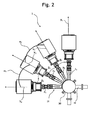
- Fig. 2 illustrates a bottom view of the pressure boosting system 2 basically similar to the one shown in Fig. 1 .
- the four pumps 4 are shown from the bottom side and thus the inlet pipes 20 can be seen.
- the inlet lines ⁇ 1 , ⁇ 2 , ⁇ 3 , ⁇ 4 connecting the pumps inlet 6 and their corresponding connection at the inlet manifold 30 are indicated.
- the angles ⁇ 1 , ⁇ 2 and ⁇ 3 between the inlet lines ⁇ 1 and ⁇ 2 , ⁇ 2 and ⁇ 3 and ⁇ 3 and ⁇ 4 respectively, are shown. All inlet lines ⁇ 1 , ⁇ 2 , ⁇ 3 and ⁇ 4 are angled relative to each other, however all the angles ⁇ 1 , ⁇ 2 and ⁇ 3 between the inlet lines are equal.
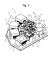
- Fig. 3 illustrates a perspective view of the pressure boosting system 2 basically similar to the one shown in Fig. 1 .
- the four pumps 4 of the pressure boosting system 2 comprise inlet pipes 20 connecting the inlet manifold 30 of the manifold system 26 and outlet pipes 18 connecting the outlet manifold 28 of the manifold system 26.
- the outlet manifold 28 of the manifold system 26 is connected to a main outlet pipe 10 and the inlet manifold 30 of the manifold system 26 is connected to a main inlet pipe 12.
- the inlet pipes 20 of all pumps 4 comprise a straight inlet pipe member 16 and the outlet pipes 18 of all pumps comprise a straight outlet pipe member 14.
- a non-return valve 62 is provided between each pump outlet 8 and the outlet manifold 28. During operation of the pressure boosting system 2 one or more pumps 4 can be turned on. The non-return valves make sure that no fluid can enter the pump outlet 8 of a pump that has been switched off.
- the fluid that is pressurised by the pressure boosting system 2 enters the inlet manifold 30 through the main connection pipe 48 via the main inlet pipe 12 and the inlet manifold 30 distributes the fluid to the pumps 4 via the inlet pipes 20.
- the fluid enters a pump 4 through the inlet 6 and leaves the pump 4 through the outlet 8 from where it is pumped through the outlet pipe 18 and enters the outlet manifold 28 of the manifold system 26 that is connected to a main outlet pipe 10.
- Each pump 4 has an inlet 6 and an outlet 8.
- the inlets 6 are provided at the axial extremity of the pumps 4 facing the manifold system 26.
- Each inlet 6 is connected to an inlet pipe 20 that is further connected to a connection pipe 36 of the inlet manifold 30 of the manifold system 26.
- the outlets 8 of the pumps 4 are provided at the radial surface of the pump sleeve and a bend section 34 is connected to each outlet 8.
- the bend section 34 is further connected to an outlet pipe 18 that is connected to a connection pipe 38 of the outlet manifold 28 of the manifold system 26 through the main pipe connection 46.
- a valve 24 is arranged in each straight inlet pipe member 16 and straight outlet pipe member 14. When a pump is removed, installed or exposed to service the valve 24 may be closed so that there is no access of a fluid to the pump.
- the valves may of any suitable type.
- Both the straight outlet pipe member 14 and the straight inlet pipe member 16 of each pump 4 extend parallel to the rotational axis of the pump X 1 , X 2 , X 3 , X 4 .
- Both the inlet manifold 30 and the outlet manifold 28 of the manifold system 26 have a cylindrical geometry and the longitudinal (cylinder) axis B of the inlet manifold 30 as well as the longitudinal (cylinder) axis A of the outlet manifold 28 of the manifold system 26 extend basically perpendicularly to the straight outlet pipe members 14, the straight inlet pipe members 16, the axes of the pump X 1 , X 2 , X 3 , X 4 , the inlet lines ⁇ 1 , ⁇ 2 , ⁇ 3 , ⁇ 4 and the outlet lines ⁇ 1 , ⁇ 2 , ⁇ 3 and ⁇ 4 .
- the longitudinal axis B of the inlet manifold 30 and the longitudinal axis A of the outlet manifold 28 of the manifold system 26
- the pressure boosting system 2 is fastened to a base plate 32 by a number of screws.
- the base plate 32 is configured to be arranged in a 90 degree corner; however it may be possible to arrange the pressure boosting system 2 on a base plate 32 having another shape or geometry. By way of example it is possible to arrange five to eight pumps on a 180 degree section of a circle.
- the manifold system 26 has an inlet manifold 30 and an outlet manifold 28 and the bottom part 28' of the outlet manifold 28 is mechanically and hermetically separated from the top part 30' of the inlet manifold 30.
- the outlet manifold 28 is arranged on the top of the inlet manifold 30 and the two manifolds 28, 30 are separated from each other by a flexible thin intermediate plate 40. It would, however; be possible to attach the outlet manifold 28 and the inlet manifold 30 together by welding or any other suitable kind of attachment.
- the outlet manifold 28 and the inlet manifold 30 may also be individually separated and displaced from one another.
- Fig. 4 illustrates a perspective view of the manifold system 26 according to the invention.
- the manifold system 26 consists of an outlet manifold 28 arranged on the top of an inlet manifold 30.
- Booth manifolds 28, 30 are cylindrical and connection pipes 36, 38 are arranged on the cylindrical periphery.
- the outlet manifold 28 comprises a main connection pipe 46 having a flange 42 that is configured to be connected to a main outlet pipe.
- the connection pipes 46, 48 are provided with sensor inlets 60 that are configured to receive a sensor.
- a pressure sensor (not shown in the figures) may be inserted into the sensor inlet by way of example.
- the inlet manifold 30 comprises a main connection pipe 48 having a flange 44 that is configured to be connected to a main inlet pipe (this is indicated in Fig. 5 ).
- Fig. 5 illustrates a perspective view of the manifold system 26 shown in Fig. 4 .
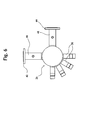
- Fig. 6 a top view of a manifold system 26 according to one embodiment of the invention is shown. It can be seen that the connection pipes 36, 38 of the inlet manifold 30 and from the outlet manifold 28 are arranged in the same side of the respective manifold system 26. It can also be seen that the main connection pipes 46, 48 are angled 90 degrees relative to each other. It is possible to arrange the main connection pipes 46, 48 in another way. The main connection pipes 46, 48 may be arranged parallel to one another by way of example.
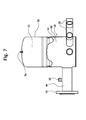
- Fig. 7 illustrates a cross sectional view of an outlet manifold 28 according to the invention.
- a diaphragm tank 50 is build into the outlet manifold 28 so that a pressure may be maintained in the outlet manifold 28 even when the pumps are not active.
- an air screw 56 is arranged in the top of the diaphragm tank 50 in the top of the diaphragm tank 50. Through this screw 56 pressurised air 52 can be filled into the diaphragm tank 50.
- the diaphragm tank 50 will change its geometry according to the pressure conditions on both sides of it and it is adapted to transfer pressure forces between the air side of the diaphragm 54 and the fluid side of the diaphragm 54.
- the outlet manifold 28 comprises a main connection pipe 46 with a flange 42 and four connection pipes 36 as well as a sensor inlet 60.
- the diaphragm tank 50 is also known as an expansion tank or an expansion vessel that typically is used in domestic hot water systems and closed water heating systems.
- the diaphragm tank 50 may be divided in two by a rubber diaphragm 54 or a diaphragm of another suitable material. As the fluid pressure increases the diaphragm moves compressing the air on its fluid free side.
- Fig. 8 illustrates four different embodiments of the manifold systems 26 according to the invention. It can be seen that the manifold connections 46, 48 can be oriented in different ways.
- Fig. 8 a) shows an embodiment where the manifold connection 46 of the outlet manifold 28 extends vertically while the manifold connection 48 of the inlet manifold 30 extends horizontally.
- Fig. 8 b) both the manifold connection 46 of the outlet manifold 28 and the manifold connection 48 of the inlet manifold 30 extend vertically.
- a diaphragm tank is integrated in the outlet manifold 28 and both the manifold connection 46 of the outlet manifold 28 and the manifold connection 48 of the inlet manifold 30 extend horizontally.
Landscapes
- Engineering & Computer Science (AREA)
- Mechanical Engineering (AREA)
- General Engineering & Computer Science (AREA)
- Details Of Reciprocating Pumps (AREA)
- Structures Of Non-Positive Displacement Pumps (AREA)
Abstract
The present invention relates to a pressure boosting system (2) comprising: two or more pumps (4) each having an inlet (6) connected to an inlet manifold (30) and an outlet (8) connected to an outlet manifold (28). The line that connects an inlet (6) and its corresponding connection at the inlet manifold (30) defines an inlet line (λ1, λ2, λ3, λ4) and the line that connects an outlet (8) and its corresponding connection at the outlet manifold (28) defines an outlet line (ω1, ω2, ω3, ω4). At least two of the inlet lines (λ1, λ2, λ3, λ4) are angled relative to each other and/or at least two of the outlet lines (ω1, ω2, ω3, ω4) are angled relative to each other. Hereby it is achieved that the pressure boosting system can be very compact.
Description
- A pressure boosting system is a multi pump system that is used to pressurise fluids. Pressure boosting systems are used in various applications. Normally pressure boosting systems comprise a plurality of pumps (typically two, three or four pumps) that are connected to a common pipe system. In the prior art pressure boosting systems the inlet pipes of the pumps are connected to an inlet manifold having a flange that is configured to be directly connected to a main inlet pipe. In the same manner the outlet pipes of the pumps are connected to an outlet manifold having a flange that is configured to be directly connected to a main outlet pipe. The manifolds typically have a tubular elongated geometry and the pumps are arranged along the longitudinal axis of the manifolds.
- In the prior pressure boosting system the inlet manifold and the outlet manifold extend parallel to one another and are individually spaced from one another. The weight of the manifolds is often exposed to the pump sleeves and accordingly, the pumps are often exposed to huge mechanical stress especially at the pump sleeve where the inlet pipes or outlet pipes are connected to the pump. Due to these mechanical stresses caused by the manifolds and valves during transportation or operation, the pipe connection of pump sleeve is often subject to damages. Leakages may result from these stresses. To overcome these mechanical stresses it is possible to support the manifolds by a mechanical support structure. This introduces more cost and mechanical restrictions regarding service of the pressure boosting system. Moreover, replacement and service of pumps requires that all pumps are disconnected. This procedure is time consuming and introduces risk of failure to the system.
- In addition to that, the prior art pressure boosting systems require a rather huge area of clearance all around the system in order to carry out inspection and service of the booster system. The manifolds of a pressure boosting system constitute a manifold system and a manifold system is required in all pressure boosting systems.
- In the prior art pressure boosting systems stagnant water is present at the blind end of the manifold even when fluid is pumped through the manifold. This stagnant water will give rise to bacteria growth. Therefore, it is an object of the present invention to provide a pressure boosting system in which stagnant water can be avoided or minimised.
- It is also an object of the present invention to provide a pressure boosting system that would make it possible to provide a pressure boosting system that exposes less mechanical stress to the pump sleeves.
- It is also an object of the present invention to provide a pressure boosting system that makes it possible to provide a pressure boosting system that does not require that all pumps are disconnected during replacement and service of a pump.
- Furthermore it, is an object of the present invention to provide a pressure boosting system that makes it possible to provide a pressure boosting system that requires a less area of clearance in order to carry out inspection and service of the pumps of the pressure boosting system. This object can be achieved by a pressure boosting system having the features defined in
claim 1. Improved embodiments are disclosed in the sub claims, the following description and the drawings. - The pressure boosting system according to the invention comprises two or more pumps each having an inlet connected to an inlet manifold and an outlet connected to an outlet manifold, where the line that connects an inlet and its corresponding connection at the inlet manifold defines an inlet line and where the line that connects an outlet and its corresponding connection at the outlet manifold defines an outlet line. At least two of the inlet lines are angled relative to each other and/or that at least two of the outlet lines are angled relative to each other.
- Hereby it is achieved that the pressure boosting system can be very compact. It is also achieved that less mechanical stress is exposed to the pump sleeve compared with the prior art pressure boosting systems.
- Moreover this pressure boosting system allows that replacement and service of a pump can be done without disconnecting all pumps.
- The pressure boosting system requires less area of clearance in order to carry out inspection and service of the pressure booster system compared with prior art pressure boosting systems.
- By the term "angled relative to each other" is meant that the lines are non parallel. The angle between adjacent pumps may be fixed so that the pumps are uniformly distributed. However, it is also possible to arrange the pumps with different angles between different sets of adjacent pumps.
- Advantageously all inlet lines are angled relative to each other and/or all outlet lines are angled relative to each other. In this way it would be possible to make a very compact pressure boosting system.
- It may be beneficial that each pump has a longitudinal axis and the longitudinal axes of the pumps are angled relative to each other. This makes it possible to arrange the pumps in a formation so that the pumps can be connected to centrally arranged manifolds. In this way a very compact pressure boosting system can be achieved.
- It may be an advantage if the outlet of each pump is connected to an outlet pipe comprising a basically straight outlet pipe member and that the inlet of each pump is connected to an inlet pipe comprising a basically straight inlet pipe member.
- Hereby a compact pressure boosting system can be achieved. Moreover, the distance between the outlets of the pumps and the main outlet as well as the distance between the inlets of the pumps and the main inlet can be minimised.
- Advantageously the longitudinal axis of each pump extends basically parallel to the corresponding inlet line and/or to the corresponding outlet line of the pump. Such a construction may be an advantage because standard components may be used and because this embodiment may be very compact.
- It may be beneficial if the inlet pipes of the pumps are directed basically towards a first common axis and the outlet pipes of the pumps are directed basically towards a second axis. In this manner it is possible to provide a very compact pressure boosting system and there is very good access to the pumps (e.g. for service of the pumps, for connection or disconnection of the pumps).
- It would be possible to arrange the axes such that the first axis and the second axis are parallel or even coinciding.
- It is possible that the pumps are arranged along an arced curve, preferable on a section of a circle. Hereby a very compact and robust pressure boosting system can be made.
- It may be an advantage if all straight outlet pipe members are of one first length and all straight inlet pipe members are of a second length. In this embodiment the pumps may be arranged on the section of a circle. Hereby it is achieved that the pressure boosting system can be made very compact and that a great part of the pipe structures may be used for both, the inlet pipe members and the outlet pipe members.
- When the inlet pipes of the pumps are directed basically towards a first common axis and the outlet pipes of the pumps are directed basically towards a second axis it may be an advantage if the longitudinal axes of the pumps extends basically perpendicular to the first axis and/or to the second axis. Hereby it may be possible to use 90 degrees connections between the outlet pipe members and a main outlet piping extending along the first and second axes. In the same way it may be possible to use 90 degrees connections between the inlet pipe members and a main inlet piping extending along the first and second axes.
- Advantageously each straight outlet pipe member and/or each straight inlet pipe member extends basically parallel to the longitudinal axis of the corresponding pump. Hereby it is possible to provide a direct and short distance connection between the pumps and the main inlet and between the pumps and the main outlets. Accordingly, a very compact and robust pressure boosting system can be achieved.
- It may be an advantage if at least some of the straight outlet pipe members and/or at least some of the straight inlet pipe members comprise a valve or are connected to a valve. This may be of great importance during pump replacement or service of the pumps.
- It may be beneficial if all straight outlet pipe members and all straight inlet pipe members comprise or are connected to a valve. Hereby it is achieved that all pumps can easily be disconnected by using the valves.
- Advantageously the inlet pipes are arranged in a first plane and the outlet pipes are arranged in a second plane extending basically parallel to the first plane.
- Accordingly, this embodiment makes it possible to provide a very compact pressure boosting system. Moreover, this embodiment may be beneficially due to the fact that all pumps may be arranged at a common pump level, that all inlets may be arranged at a common inlet level, that all outlets may be arranged at a common outlet level, that all outlet pipe members and all inlet pipe members may be arranged parallel.
- It is possible that the inlet pipes and outlet pipes are connected to a manifold system that comprises: a basically cylindrical inlet manifold having a longitudinal axis and being arranged adjacent to a basically cylindrical outlet manifold having a longitudinal axis; where the inlet manifold comprises a connection to the main inlet and a number of connections for the inlet pipes of the pumps and where the outlet manifold comprises a connection to the main outlet and a number of connections for the outlet pipes of the pumps.
- This embodiment makes it possible to provide a very compact and service friendly connection of the pumps to the main inlet and to the main outlet.
- It is possible that the longitudinal axis of the inlet manifold of the manifold system and the longitudinal axis of the outlet manifold of the manifold system are parallel and basically vertically directed.
- Advantageously the pumps are arranged on a base plate. This embodiment makes it possible to preassemble the pressure boosting system and to ensure that the pressure boosting system is fixed firmly.
- Hereby it is achieved that the inlet manifold and the outlet manifold of the manifold system can be arranged in a manner such that the manifold system is very compact. Moreover, it may be possible to use an inlet manifold having the same geometry as the outlet manifold and vice versa.
- Even though both the outlet manifold and the inlet manifold have a basically cylindrical structure the shape and/or diameter of the outlet manifold and the inlet manifold may differ.
- It is possible to provide a pressure boosting system having a manifold system comprising an outlet manifold and an inlet manifold with basically the same geometry.
- Advantageously a valve is provided between the manifold system and each pump inlet and between the manifold system and each pump outlet.
- It may be an advantage if the pumps are multistage pumps. Multistage pumps are widely used in pressure boosting systems and they are capable of generating the required pressure and flow. The multistage pumps may be arranged horizontally.
- It may be beneficial if each manifold comprises a number of connection pipes provided at the cylindrical periphery of the manifold and the connection pipes extend radially preferably perpendicularly to the longitudinal axis of the manifolds.
- Advantageously the inlet pipes of the pumps extend basically horizontally from the pumps to the inlet manifold and the outlet pipes of the pumps comprise a bend section connecting the outlets with the straight outlet pipe members. The straight outlet pipe members extend basically horizontally to the outlet manifold and the outlet manifold of the manifold system is arranged above and adjacent to the inlet manifold of the manifold system and that the outlet manifold of the manifold system and the inlet manifold of the manifold system are separated from each other.
- Accordingly, it is possible to provide a very compact and robust pressure boosting system.
- The pressure boosting system according to the invention may comprise a manifold system that comprises a manifold having:
- a manifold space configured to receive a fluid;
- a main connection pipe configured to connect the manifold space to a main pipe and
- a number of connection pipes each configured to connect the manifold space to a pump.
- At least some connection pipes of the manifold are angled relative to each other.
- In this way the manifold system can be arranged centrally relative to the pumps of the pressure boosting system and thus the pressure boosting system can be very compact. It is also achieved that less mechanical stress is exposed to the pump sleeve compared with the prior art pressure boosting systems.
- Moreover the manifold system makes it possible to build a pressure boosting system that allows for replacement and service of a pump without disconnecting all pumps.
- When the manifold system is used the pressure boosting system requires less area of clearance in order to carry out inspection and service of the pressure booster system compared with prior art pressure boosting systems.
- All the connection pipes of the manifold may be angled relative to each other. This way of arranging the connection pipes makes it possible to simplify the way of producing the manifold system and makes it possible to build a very compact pressure boosting system.
- The manifold may be cylindrical and the connection pipes may be arranged at the cylindrical periphery of the manifold. Hereby the manifold can be robust and can be produced easily.
- It is possible to arrange the connection pipes so that they extend basically perpendicularly to the longitudinal axis of the manifold.
- It is possible to have a pressure boosting system in which a diaphragm tank is arranged on the outlet manifold or that a diaphragm is build into the outlet manifold. Hereby a pressure can be maintained in the outlet manifold when the last pump in operation is switched off. Hereby pressure energy can be stored in the outlet manifold and a fluid can be pressurised even when there is no pump activity.
- It is furthermore possible to configure the manifold system so that the longitudinal axes of the connection pipes span a first plane that is basically perpendicular to the longitudinal axis of the manifold and that the main connection pipe extends basically parallel to the first plane. This configuration will take up less space than prior art manifold systems and make it possible to easily connect pumps of similar type to the manifold system.
- The manifold system may comprise an inlet manifold having a longitudinal axis and being arranged adjacent to an outlet manifold having a longitudinal axis and furthermore the axes of the inlet manifold and the outlet manifold are basically parallel to each other. It may be an advantage to use a manifold system according to this configuration because both the inlet manifold and the outlet manifold make it possible to achieve a very compact pressure boosting system.
- It is possible to arrange the inlet manifold and the outlet manifold in several configurations. By way of example the inlet manifold and the outlet manifold may be individually spaced from each other. However, it is also possible to weld the inlet manifold and the outlet manifold or connect the inlet manifold and the outlet manifold together by mechanic means. The inlet manifold and the outlet manifold may for instance be arranged on the top of each other or by a side by side configuration.
- It is possible that the inlet manifold and the outlet manifold are arranged adjacent to each other and that the longitudinal axes of the inlet manifold and the outlet manifold are basically parallel to each other. Hereby a compact manifold system can be achieved.
- It is possible that the inlet manifold and the outlet manifold are build together into one unit. Still the two manifolds may be produced separately. Building the manifolds into the same unit may be achieved in several ways. By way of example two manifolds may be welded together or fixed together by mechanical means. It would be possible to produce the manifold by one or more moulding processes by way of example.
- The connection pipes of the inlet manifold may be evenly distributed so that the angle between the longitudinal axes of all adjacent connection pipes are basically the same and/or the connection pipes of the outlet manifold may be evenly distributed so that the angle between the longitudinal axes of all adjacent connection pipes is basically the same. In this way it would be possible to distribute the pumps evenly around the inlet manifold and the outlet manifold and to provide a very compact pressure boosting system.
- It is possible to provide a pressure boosting system comprising a manifold system according to any of the described manifold systems.
- The inlet manifold and the outlet manifold may have the same diameter. Accordingly, it is possible to produce the inlet manifold and the outlet manifold in the same way by using the same production tools.
- The connection pipes of the inlet manifold may be arranged in a manner so that the longitudinal axes of the connection pipes of the inlet manifold span a second plane that is basically perpendicularly to the longitudinal axis of the inlet manifold and the main connection pipe may extend basically parallel to the first plane and the connection pipes of the outlet manifold may be arranged in a manner so the longitudinal axes of the connection pipes of the outlet manifold span a third plane that is basically perpendicularly to the longitudinal axis of the outlet manifold and that the main connection pipe extend basically parallel to the second plane and the second plane and the third plane are basically parallel to each other.
- Hereby a very compact and robust pressure boosting system can be made. Moreover, this embodiment may be beneficial due to the fact that the all pumps may be arranged at a common pump level, that all inlets may be arranged at a common inlet level, that all outlets may be arranged at a common outlet level, that all outlet pipe members and all inlet pipe members may be arranged parallel.
- The inlet pipes of the pumps may extend basically horizontally from the pumps to the inlet manifold and the outlet pipes of the pumps may comprise a bend section connecting the outlets with the straight outlet pipe members. The straight outlet pipe members may extend basically horizontally from the pumps to the outlet manifold and the outlet manifold may be arranged above and adjacent to the inlet manifold and the outlet manifold and the inlet manifold may be hermetically separated from each other.
- The present invention will become more fully understood from the detailed description given herein below and the accompanying drawings, which are given by way of illustration only, and thus, they are not limitative of the present invention, and wherein:
- Fig. 1
- shows a top view of one pressure boosting system accord-ing to the invention;
- Fig. 2
- shows a bottom view of one pressure boosting system shown in
Fig. 1 without base plate, - Fig. 3
- shows a perspective side view of a pressure boosting sys-tem according to the invention;
- Fig. 4
- shows a front view of a one manifold system according to one embodiment of the invention;
- Fig. 5
- shows a perspective view of the manifold system shown in
Fig. 4 ; - Fig. 6
- shows a top view of the manifold system shown in
Fig. 4 andFig. 5 ; - Fig. 7
- shows a cross sectional view of a manifold system accord-ing to another embodiment of the invention, and
- Fig. 8
- shows different embodiments of the manifold systems ac-cording to the invention.
- Other objects and further scope of applicability of the present invention will become apparent from the detailed description given hereinafter. It should be understood, however, that the detailed description and specific examples, an indication of preferred embodiments of the invention, are given by way of illustration only, since various changes and modifications within the spirit and scope of the invention will be become apparent to those skilled in the art from this detailed description.
- Referring now in detail to the drawings for the purpose of illustrating preferred embodiments of the present invention, elements of a pressure boosting system comprising a
manifold system 26 according to the present invention are illustrated inFig. 1 . Thepressure boosting system 2 comprises fourpumps 4 arranged along a section of a circle C. The pumps 4 have longitudinal axes X1, X2, X3 X4 which are rotational axes of the rotor and which are angled relative to each other. The angle α1 between the pump having a longitudinal axis X1 and the pump having a longitudinal axis X2 is similar to the angle α2 between the pump having the longitudinal axis X2 and the pump having the longitudinal axis X3. In fact the angle α3 between the pump having the longitudinal axis X3 and the pump having the longitudinal axis X4 is similar to both, the angle α1 and the angle α2. - It would, however, be possible to arrange the
pumps 4 differently and still remain thepumps 4 arranged along a section of a circle. This may be done by choosing the angle α1 different from the angle α2 and α3. - The
pumps 4 are connected to a manifold system (26) comprising anoutlet manifold 28 and an inlet manifold 30 (shown inFig. 3 ). Theoutlet manifold 28 is connected to amain outlet pipe 10. Theoutlet manifold 28 is connected to theoutlets 8 of thepumps 4 via apipe system 22. SinceFig. 1 shows a top view of thepumps 4 only thepump outlet 8 can be seen. The input manifold 30 (as can be seen inFig. 2 and3 ) comprises amain connection pipe 48 that is provided with aflange 44. Thisflange 44 is bearing against flange 44' of themain outlet pipe 12. Theflanges 44 and 44' may preferable be mechanically attached to another with a sealing in between. Theoutput manifold 28 comprises amain connection pipe 46 that has aflange 42 bearing against a flange 42' of amain outlet pipe 10. - For each
pump 4 the outlet line ω1, ω2, ω3 and ω4 connecting thepump outlets 8 to the corresponding connection at theoutlet manifold 28 is indicated. The angles β1, β2 and β3 between the outlet lines ω1 and ω2, ω2 and ω3 and ω3 and ω4 respectively, are indicated. It can be seen that even though all outlet lines ω1, ω2, ω3 and ω4 are angled relative to each other, the angles β1, β2 and β3 between the outlet lines are equal. -
Fig. 2 illustrates a bottom view of thepressure boosting system 2 basically similar to the one shown inFig. 1 . The fourpumps 4 are shown from the bottom side and thus theinlet pipes 20 can be seen. The inlet lines λ1, λ2, λ3, λ4 connecting the pumps inlet 6 and their corresponding connection at theinlet manifold 30 are indicated. The angles α1, α2 and α3 between the inlet lines λ1 and λ2, λ2 and λ3 and λ3 and λ4 respectively, are shown. All inlet lines λ1, λ2, λ3 and λ4 are angled relative to each other, however all the angles α1, α2 and α3 between the inlet lines are equal. -
Fig. 3 illustrates a perspective view of thepressure boosting system 2 basically similar to the one shown inFig. 1 . The fourpumps 4 of thepressure boosting system 2 compriseinlet pipes 20 connecting theinlet manifold 30 of themanifold system 26 andoutlet pipes 18 connecting theoutlet manifold 28 of themanifold system 26. Theoutlet manifold 28 of themanifold system 26 is connected to amain outlet pipe 10 and theinlet manifold 30 of themanifold system 26 is connected to amain inlet pipe 12. Theinlet pipes 20 of allpumps 4 comprise a straightinlet pipe member 16 and theoutlet pipes 18 of all pumps comprise a straightoutlet pipe member 14. Anon-return valve 62 is provided between eachpump outlet 8 and theoutlet manifold 28. During operation of thepressure boosting system 2 one ormore pumps 4 can be turned on. The non-return valves make sure that no fluid can enter thepump outlet 8 of a pump that has been switched off. - The fluid that is pressurised by the
pressure boosting system 2 enters theinlet manifold 30 through themain connection pipe 48 via themain inlet pipe 12 and theinlet manifold 30 distributes the fluid to thepumps 4 via theinlet pipes 20. The fluid enters apump 4 through the inlet 6 and leaves thepump 4 through theoutlet 8 from where it is pumped through theoutlet pipe 18 and enters theoutlet manifold 28 of themanifold system 26 that is connected to amain outlet pipe 10. - Each
pump 4 has an inlet 6 and anoutlet 8. The inlets 6 are provided at the axial extremity of thepumps 4 facing themanifold system 26. Each inlet 6 is connected to aninlet pipe 20 that is further connected to aconnection pipe 36 of theinlet manifold 30 of themanifold system 26. Theoutlets 8 of thepumps 4 are provided at the radial surface of the pump sleeve and abend section 34 is connected to eachoutlet 8. Thebend section 34 is further connected to anoutlet pipe 18 that is connected to aconnection pipe 38 of theoutlet manifold 28 of themanifold system 26 through themain pipe connection 46. - A
valve 24 is arranged in each straightinlet pipe member 16 and straightoutlet pipe member 14. When a pump is removed, installed or exposed to service thevalve 24 may be closed so that there is no access of a fluid to the pump. The valves may of any suitable type. - Both the straight
outlet pipe member 14 and the straightinlet pipe member 16 of eachpump 4 extend parallel to the rotational axis of the pump X1, X2, X3, X4. Both theinlet manifold 30 and theoutlet manifold 28 of themanifold system 26 have a cylindrical geometry and the longitudinal (cylinder) axis B of theinlet manifold 30 as well as the longitudinal (cylinder) axis A of theoutlet manifold 28 of themanifold system 26 extend basically perpendicularly to the straightoutlet pipe members 14, the straightinlet pipe members 16, the axes of the pump X1, X2, X3, X4, the inlet lines λ1, λ2, λ3, λ4 and the outlet lines ω1, ω2, ω3 and ω4. In fact, the longitudinal axis B of theinlet manifold 30 and the longitudinal axis A of theoutlet manifold 28 of themanifold system 26 are basically parallel to one another. - The
pressure boosting system 2 is fastened to abase plate 32 by a number of screws. Thebase plate 32 is configured to be arranged in a 90 degree corner; however it may be possible to arrange thepressure boosting system 2 on abase plate 32 having another shape or geometry. By way of example it is possible to arrange five to eight pumps on a 180 degree section of a circle. - The
manifold system 26 has aninlet manifold 30 and anoutlet manifold 28 and the bottom part 28' of theoutlet manifold 28 is mechanically and hermetically separated from the top part 30' of theinlet manifold 30. Theoutlet manifold 28 is arranged on the top of theinlet manifold 30 and the twomanifolds intermediate plate 40. It would, however; be possible to attach theoutlet manifold 28 and theinlet manifold 30 together by welding or any other suitable kind of attachment. Theoutlet manifold 28 and theinlet manifold 30 may also be individually separated and displaced from one another. -
Fig. 4 illustrates a perspective view of themanifold system 26 according to the invention. Themanifold system 26 consists of anoutlet manifold 28 arranged on the top of aninlet manifold 30. Booth manifolds 28, 30 are cylindrical andconnection pipes outlet manifold 28 comprises amain connection pipe 46 having aflange 42 that is configured to be connected to a main outlet pipe. Theconnection pipes sensor inlets 60 that are configured to receive a sensor. A pressure sensor (not shown in the figures) may be inserted into the sensor inlet by way of example. In the same manner theinlet manifold 30 comprises amain connection pipe 48 having aflange 44 that is configured to be connected to a main inlet pipe (this is indicated inFig. 5 ). -
Fig. 5 illustrates a perspective view of themanifold system 26 shown inFig. 4 . - In
Fig. 6 a top view of amanifold system 26 according to one embodiment of the invention is shown. It can be seen that theconnection pipes inlet manifold 30 and from theoutlet manifold 28 are arranged in the same side of therespective manifold system 26. It can also be seen that themain connection pipes main connection pipes main connection pipes -
Fig. 7 illustrates a cross sectional view of anoutlet manifold 28 according to the invention. Adiaphragm tank 50 is build into theoutlet manifold 28 so that a pressure may be maintained in theoutlet manifold 28 even when the pumps are not active. In the top of thediaphragm tank 50 anair screw 56 is arranged. Through thisscrew 56 pressurisedair 52 can be filled into thediaphragm tank 50. Thediaphragm tank 50 will change its geometry according to the pressure conditions on both sides of it and it is adapted to transfer pressure forces between the air side of thediaphragm 54 and the fluid side of thediaphragm 54. Theoutlet manifold 28 comprises amain connection pipe 46 with aflange 42 and fourconnection pipes 36 as well as asensor inlet 60. - The
diaphragm tank 50 is also known as an expansion tank or an expansion vessel that typically is used in domestic hot water systems and closed water heating systems. Thediaphragm tank 50 may be divided in two by arubber diaphragm 54 or a diaphragm of another suitable material. As the fluid pressure increases the diaphragm moves compressing the air on its fluid free side. -
Fig. 8 illustrates four different embodiments of themanifold systems 26 according to the invention. It can be seen that themanifold connections Fig. 8 a) shows an embodiment where themanifold connection 46 of theoutlet manifold 28 extends vertically while themanifold connection 48 of theinlet manifold 30 extends horizontally. InFig. 8 b) both themanifold connection 46 of theoutlet manifold 28 and themanifold connection 48 of theinlet manifold 30 extend vertically. InFig. 8 c) themanifold connection 46 of theoutlet manifold 28 extends horizontally while themanifold connection 48 of theinlet manifold 30 extends vertically. InFig. 8 d) a diaphragm tank is integrated in theoutlet manifold 28 and both themanifold connection 46 of theoutlet manifold 28 and themanifold connection 48 of theinlet manifold 30 extend horizontally. -
- 2 -
- Pressure boosting system
- 4 -
- Pump
- 6 -
- Inlet
- 8 -
- Outlet
- 10 -
- Main outlet pipe
- 12 -
- Main inlet pipe
- 14 -
- Straight outlet pipe member
- 16 -
- Straight inlet pipe member
- 18 -
- Outlet pipe
- 20 -
- Inlet pipe
- 22 -
- Pipe system
- 24 -
- Valve
- 26 -
- Manifold system
- 28 -
- Outlet manifold
- 28' -
- Bottom part of the outlet manifold
- 30 -
- Inlet manifold
- 30' -
- Top part of the inlet manifold
- 32 -
- Base plate
- 34 -
- Bend section
- A -
- Axis
- B -
- Axis
- X1, X2, X3, X4, -
- Axes of the pumps
- 36, 38 -
- Connection pipes
- 40 -
- Intermediate plate
- ω1, ω2, ω3, ω4 -
- Outlet lines
- λ1, λ2, λ3, λ4 -
- Inlet lines
- 42, 44, 42', 44' -
- Flanges
- 46, 48 -
- Main connection pipes
- 50 -
- Diaphragm tank
- 52 -
- Pressurised air
- 54 -
- Flexible diaphragm
- 56 -
- Air screw
- 58 -
- Manifold space
- 60 -
- Sensor inlet
- C -
- Section of a circle
- 62 -
- Non-return valves
Claims (15)
- A pressure boosting system (2) comprising:- two or more pumps (4) each having:- an inlet (6) connected to an inlet manifold (30) and- an outlet (8) connected to an outlet manifold (28);- where the line that connects an inlet (6) and its corresponding connection at the inlet manifold (30) defines an inlet line (λ1, λ2, λ3, λ4) and- where the line that connects an outlet (8) and its corresponding connection at the outlet manifold (28) defines an outlet line (ω1, ω2, ω3, ω4)characterised in that
at least two of the inlet lines (λ1, λ2, λ3, λ4) are angled relative to each other and/or that at least two of the outlet lines (ω1, ω2, ω3, ω4) are angled relative to each other. - A pressure boosting system (2) according to claim 1 characterised in that all inlet lines (λ1, λ2, λ3, λ4) are angled relative to each other and/or that all outlet lines (ω1, ω2, ω3, ω4) are angled relative to each other.
- A pressure boosting system (2) according to claim 1 or claim 2 characterised in that each pump (4) has a longitudinal axis (X1, X2, X3, X4) and that the longitudinal axes (X1, X2, X3, X4) of the pumps (4) are angled relative to each other.
- A pressure boosting system (2) according to one of the preceding claims characterised in that:- the outlet (8) of each pump (4) is connected to an outlet pipe (18) comprising a basically straight outlet pipe member (14) and- that the inlet (6) of each pump (4) is connected to an inlet pipe (20) comprising a basically straight inlet pipe member (16).
- A pressure boosting system (2) according to one of the preceding claims characterised in that the longitudinal axis (X1, X2, X3, X4) of each pump (4) extend basically parallel to the corresponding inlet line (λ1, λ2, λ3, λ4) and/or to the corresponding outlet line (ω1, ω2, ω3, ω4) of the pump (4).
- A pressure boosting system (2) according to one of the preceding claims characterised in that the inlet pipes (20) of the pumps (4) are directed basically towards a first common axis and that the outlet pipes (18) of the pumps (4) are directed basically towards a second axis.
- A pressure boosting system (2) according to one of the preceding claims characterised in that the pumps (4) are arranged along an arced curve, preferable on a section of a circle.
- A pressure boosting system (2) according to claim 6 characterised in that the longitudinal axes (X1, X2, X3, X4) of the pumps (4) extend basically perpendicular to the first axis and/or to the second axis.
- A pressure boosting system (2) according to one of the claims 4-8 characterised in that each straight outlet pipe member (14) and/or each straight inlet pipe member (16) extend basically parallel to the longitudinal axis (X1, X2, X3, X4) of the corresponding pump (4).
- A pressure boosting system (2) according to one of the preceding claims characterised in that the inlet pipes (20) are arranged in a first plane and that the outlet pipes (18) are arranged in a second plane extending basically parallel to the first plane.
- A pressure boosting system (2) according to one of the preceding claims characterised in that the inlet pipes (20) and outlet pipes (18) are connected to a manifold system (26) that comprises:- a basically cylindrical inlet manifold (30) having a longitudinal axis (B) and being arranged adjacent to;- a basically cylindrical outlet manifold (28) having a longitudinal axis (A);where the inlet manifold (30) comprises a connection to the main inlet (12) and a number of connections (36) for the inlet pipes (20) of the pumps (4) and where the outlet manifold (28) comprises a connection to the main outlet (10) and a number of connections (38) for the outlet pipes (18) of the pumps (4).
- A pressure boosting system (2) according to claim 11, characterised in that the longitudinal axis (B) of the inlet manifold (30) of the manifold system (26) and the longitudinal axis (A) of the outlet manifold (28) of the manifold system (26) are parallel and basically vertically directed.
- A pressure boosting system (2) according to one of the claims 11-12 characterised in that each manifold comprises a number of connection pipes (36, 38) provided at the cylindrical periphery of the manifold and that the connections pipes extend radially preferably perpendicular to the longitudinal axis of the manifolds (A, B).
- A pressure boosting system (2) according to one of the preceding claims 4-13 characterised in that- the inlet pipes (20) of the pumps (4) extend basically horizontally from the pumps (4) to the inlet manifold (30) ;- that outlet pipes (18) of the pumps (4) comprise a bend section (34) connecting the outlets (8) with the straight outlet pipe members (14);- the straight outlet pipe members (14) extend basically horizontally to the outlet manifold (28);- that the outlet manifold (28) of the manifold system (26) is arranged above and adjacent to the inlet manifold (30) of the manifold system (26) and- that the outlet manifold (28) of the manifold system (26) and the inlet manifold (30) of the manifold system (26) are separated from each other.
- A pressure boosting system (2) according to one of the preceding claims characterised in that a diaphragm tank is arranged on the outlet manifold or that a diaphragm is build into the outlet manifold.
Priority Applications (4)
| Application Number | Priority Date | Filing Date | Title |
|---|---|---|---|
| EP11003042A EP2511528A1 (en) | 2011-04-12 | 2011-04-12 | Pressure boosting system |
| PCT/EP2012/056450 WO2012140012A1 (en) | 2011-04-12 | 2012-04-10 | Pressure boosting system |
| CN201280018225.9A CN103477072B (en) | 2011-04-12 | 2012-04-10 | Supercharging system |
| EP12714305.5A EP2697513B1 (en) | 2011-04-12 | 2012-04-10 | Pressure boosting system |
Applications Claiming Priority (1)
| Application Number | Priority Date | Filing Date | Title |
|---|---|---|---|
| EP11003042A EP2511528A1 (en) | 2011-04-12 | 2011-04-12 | Pressure boosting system |
Publications (1)
| Publication Number | Publication Date |
|---|---|
| EP2511528A1 true EP2511528A1 (en) | 2012-10-17 |
Family
ID=44212207
Family Applications (2)
| Application Number | Title | Priority Date | Filing Date |
|---|---|---|---|
| EP11003042A Withdrawn EP2511528A1 (en) | 2011-04-12 | 2011-04-12 | Pressure boosting system |
| EP12714305.5A Not-in-force EP2697513B1 (en) | 2011-04-12 | 2012-04-10 | Pressure boosting system |
Family Applications After (1)
| Application Number | Title | Priority Date | Filing Date |
|---|---|---|---|
| EP12714305.5A Not-in-force EP2697513B1 (en) | 2011-04-12 | 2012-04-10 | Pressure boosting system |
Country Status (3)
| Country | Link |
|---|---|
| EP (2) | EP2511528A1 (en) |
| CN (1) | CN103477072B (en) |
| WO (1) | WO2012140012A1 (en) |
Cited By (1)
| Publication number | Priority date | Publication date | Assignee | Title |
|---|---|---|---|---|
| WO2014004108A1 (en) * | 2012-06-28 | 2014-01-03 | Heatcraft Refrigeration Products Llc | Compressor manifold assembly |
Citations (5)
| Publication number | Priority date | Publication date | Assignee | Title |
|---|---|---|---|---|
| US3542491A (en) * | 1969-05-27 | 1970-11-24 | Joseph W Newman | Fluid pump |
| DE4001418A1 (en) * | 1990-01-19 | 1991-07-25 | Buchen Smb Gmbh | High pressure plunger pump - has outlet hoses connecting to accumulator and of same length |
| EP1936187A1 (en) * | 2006-12-22 | 2008-06-25 | F.LLI Tabanelli S.N.C. Di Tabanelli Paolo & C. | Multiple membrane pump for food liquids and the like |
| US20080298982A1 (en) * | 2005-11-18 | 2008-12-04 | Carsten Pabst | Multi-Piston Pump |
| US7766626B2 (en) * | 2003-11-18 | 2010-08-03 | Robert Bosch Gmbh | Multipiston pump |
Family Cites Families (1)
| Publication number | Priority date | Publication date | Assignee | Title |
|---|---|---|---|---|
| FR1006224A (en) * | 1947-12-06 | 1952-04-21 | Control device for pumps for supplying hydraulic presses |
-
2011
- 2011-04-12 EP EP11003042A patent/EP2511528A1/en not_active Withdrawn
-
2012
- 2012-04-10 WO PCT/EP2012/056450 patent/WO2012140012A1/en not_active Ceased
- 2012-04-10 CN CN201280018225.9A patent/CN103477072B/en not_active Expired - Fee Related
- 2012-04-10 EP EP12714305.5A patent/EP2697513B1/en not_active Not-in-force
Patent Citations (5)
| Publication number | Priority date | Publication date | Assignee | Title |
|---|---|---|---|---|
| US3542491A (en) * | 1969-05-27 | 1970-11-24 | Joseph W Newman | Fluid pump |
| DE4001418A1 (en) * | 1990-01-19 | 1991-07-25 | Buchen Smb Gmbh | High pressure plunger pump - has outlet hoses connecting to accumulator and of same length |
| US7766626B2 (en) * | 2003-11-18 | 2010-08-03 | Robert Bosch Gmbh | Multipiston pump |
| US20080298982A1 (en) * | 2005-11-18 | 2008-12-04 | Carsten Pabst | Multi-Piston Pump |
| EP1936187A1 (en) * | 2006-12-22 | 2008-06-25 | F.LLI Tabanelli S.N.C. Di Tabanelli Paolo & C. | Multiple membrane pump for food liquids and the like |
Cited By (2)
| Publication number | Priority date | Publication date | Assignee | Title |
|---|---|---|---|---|
| WO2014004108A1 (en) * | 2012-06-28 | 2014-01-03 | Heatcraft Refrigeration Products Llc | Compressor manifold assembly |
| US9145880B2 (en) | 2012-06-28 | 2015-09-29 | Heatcraft Refrigeration Products Llc | Compressor manifold assembly |
Also Published As
| Publication number | Publication date |
|---|---|
| WO2012140012A1 (en) | 2012-10-18 |
| EP2697513A1 (en) | 2014-02-19 |
| CN103477072B (en) | 2016-06-01 |
| CN103477072A (en) | 2013-12-25 |
| EP2697513B1 (en) | 2020-11-18 |
Similar Documents
| Publication | Publication Date | Title |
|---|---|---|
| AU658127B2 (en) | Secondarily contained fluid supply system | |
| US7946810B2 (en) | Multistage pump assembly | |
| US8172523B2 (en) | Multistage pump assembly having removable cartridge | |
| EP2569568B1 (en) | In-line pressure balanced expansion joint for piping and ducting systems with circular cross section and internally located tie rods | |
| EP2671014B1 (en) | Split pressure vessel for two flow processing | |
| RU2011118239A (en) | SYSTEMS AND METHODS FOR MEETING CONSTRUCTION REQUIREMENTS FOR AIRCRAFT LOADS WITH ADDITIONAL FUEL CAPACITY | |
| US7191789B2 (en) | Transition adaptor and component modules for hydronic heating | |
| EP2511528A1 (en) | Pressure boosting system | |
| US20180216320A1 (en) | Modular, adaptable and expandable booster pump system | |
| WO2012140018A1 (en) | Manifold system | |
| CN211739961U (en) | Splice and connection assembly | |
| US7775762B2 (en) | Pump header body and modular manifold | |
| AU2023249184B2 (en) | Frame for use subsea | |
| ES2395366B1 (en) | Quick coupling manifold adapted in particular to heating systems or sanitary systems | |
| US10969028B2 (en) | Shrouded valve assembly | |
| US10844971B2 (en) | Shrouded valve assembly | |
| EP3670927B1 (en) | Pump unit and pump system | |
| CN214579511U (en) | Ventilating duct plate type flat welding flange | |
| EP3855020B1 (en) | Manifold for an electric pump and electric pump with such manifold | |
| KR20240046493A (en) | Hollow fiber membrane module unit | |
| CN110500342B (en) | Hydraulic system | |
| CN218911583U (en) | Non-negative pressure water supply device | |
| CN216279993U (en) | Water supply pipe with multiple water outlets | |
| CN104279376A (en) | Multi-part concentric manifold and method of making the manifold | |
| EP3394492B1 (en) | A fitting assembly for corrugated tubing |
Legal Events
| Date | Code | Title | Description |
|---|---|---|---|
| PUAI | Public reference made under article 153(3) epc to a published international application that has entered the european phase |
Free format text: ORIGINAL CODE: 0009012 |
|
| AK | Designated contracting states |
Kind code of ref document: A1 Designated state(s): AL AT BE BG CH CY CZ DE DK EE ES FI FR GB GR HR HU IE IS IT LI LT LU LV MC MK MT NL NO PL PT RO RS SE SI SK SM TR |
|
| AX | Request for extension of the european patent |
Extension state: BA ME |
|
| STAA | Information on the status of an ep patent application or granted ep patent |
Free format text: STATUS: THE APPLICATION IS DEEMED TO BE WITHDRAWN |
|
| 18D | Application deemed to be withdrawn |
Effective date: 20130418 |