EP2511453B1 - Clip for securing a lock barrel in a lock body - Google Patents
Clip for securing a lock barrel in a lock body Download PDFInfo
- Publication number
- EP2511453B1 EP2511453B1 EP20120175620 EP12175620A EP2511453B1 EP 2511453 B1 EP2511453 B1 EP 2511453B1 EP 20120175620 EP20120175620 EP 20120175620 EP 12175620 A EP12175620 A EP 12175620A EP 2511453 B1 EP2511453 B1 EP 2511453B1
- Authority
- EP
- European Patent Office
- Prior art keywords
- lock
- clip
- assembly
- barrel
- main body
- Prior art date
- Legal status (The legal status is an assumption and is not a legal conclusion. Google has not performed a legal analysis and makes no representation as to the accuracy of the status listed.)
- Expired - Lifetime
Links
Images


Classifications
-
- E—FIXED CONSTRUCTIONS
- E05—LOCKS; KEYS; WINDOW OR DOOR FITTINGS; SAFES
- E05B—LOCKS; ACCESSORIES THEREFOR; HANDCUFFS
- E05B9/00—Lock casings or latch-mechanism casings ; Fastening locks or fasteners or parts thereof to the wing
- E05B9/04—Casings of cylinder locks
- E05B9/041—Double cylinder locks
- E05B9/042—Stators consisting of multiple parts being assembled together
-
- E—FIXED CONSTRUCTIONS
- E05—LOCKS; KEYS; WINDOW OR DOOR FITTINGS; SAFES
- E05B—LOCKS; ACCESSORIES THEREFOR; HANDCUFFS
- E05B27/00—Cylinder locks or other locks with tumbler pins or balls that are set by pushing the key in
- E05B27/0003—Details
- E05B27/0014—Stators
-
- E—FIXED CONSTRUCTIONS
- E05—LOCKS; KEYS; WINDOW OR DOOR FITTINGS; SAFES
- E05B—LOCKS; ACCESSORIES THEREFOR; HANDCUFFS
- E05B9/00—Lock casings or latch-mechanism casings ; Fastening locks or fasteners or parts thereof to the wing
- E05B9/08—Fastening locks or fasteners or parts thereof, e.g. the casings of latch-bolt locks or cylinder locks to the wing
- E05B9/084—Fastening of lock cylinders, plugs or cores
- E05B9/086—Fastening of rotors, plugs or cores to an outer stator
-
- E—FIXED CONSTRUCTIONS
- E05—LOCKS; KEYS; WINDOW OR DOOR FITTINGS; SAFES
- E05B—LOCKS; ACCESSORIES THEREFOR; HANDCUFFS
- E05B9/00—Lock casings or latch-mechanism casings ; Fastening locks or fasteners or parts thereof to the wing
- E05B9/10—Coupling devices for the two halves of double cylinder locks, e.g. devices for coupling the rotor with the locking cam
-
- F—MECHANICAL ENGINEERING; LIGHTING; HEATING; WEAPONS; BLASTING
- F16—ENGINEERING ELEMENTS AND UNITS; GENERAL MEASURES FOR PRODUCING AND MAINTAINING EFFECTIVE FUNCTIONING OF MACHINES OR INSTALLATIONS; THERMAL INSULATION IN GENERAL
- F16B—DEVICES FOR FASTENING OR SECURING CONSTRUCTIONAL ELEMENTS OR MACHINE PARTS TOGETHER, e.g. NAILS, BOLTS, CIRCLIPS, CLAMPS, CLIPS OR WEDGES; JOINTS OR JOINTING
- F16B21/00—Means for preventing relative axial movement of a pin, spigot, shaft or the like and a member surrounding it; Stud-and-socket releasable fastenings
- F16B21/10—Means for preventing relative axial movement of a pin, spigot, shaft or the like and a member surrounding it; Stud-and-socket releasable fastenings by separate parts
- F16B21/16—Means for preventing relative axial movement of a pin, spigot, shaft or the like and a member surrounding it; Stud-and-socket releasable fastenings by separate parts with grooves or notches in the pin or shaft
- F16B21/18—Means for preventing relative axial movement of a pin, spigot, shaft or the like and a member surrounding it; Stud-and-socket releasable fastenings by separate parts with grooves or notches in the pin or shaft with circlips or like resilient retaining devices, i.e. resilient in the plane of the ring or the like; Details
- F16B21/186—Means for preventing relative axial movement of a pin, spigot, shaft or the like and a member surrounding it; Stud-and-socket releasable fastenings by separate parts with grooves or notches in the pin or shaft with circlips or like resilient retaining devices, i.e. resilient in the plane of the ring or the like; Details external, i.e. with contracting action
-
- Y—GENERAL TAGGING OF NEW TECHNOLOGICAL DEVELOPMENTS; GENERAL TAGGING OF CROSS-SECTIONAL TECHNOLOGIES SPANNING OVER SEVERAL SECTIONS OF THE IPC; TECHNICAL SUBJECTS COVERED BY FORMER USPC CROSS-REFERENCE ART COLLECTIONS [XRACs] AND DIGESTS
- Y10—TECHNICAL SUBJECTS COVERED BY FORMER USPC
- Y10T—TECHNICAL SUBJECTS COVERED BY FORMER US CLASSIFICATION
- Y10T70/00—Locks
- Y10T70/70—Operating mechanism
- Y10T70/7441—Key
- Y10T70/7486—Single key
- Y10T70/7508—Tumbler type
- Y10T70/7559—Cylinder type
- Y10T70/7565—Plural tumbler sets
Definitions
- This invention is concerned with a lock body assembly for a double lock barrel assembly.
- the invention in its various aspects has been designed for a double lock barrel assembly which can be installed in a door, for example, and enable keyed access from either side, usually operating a centrally located latch mechanism.
- JP 61 182412 illustrates a generally planar clip having, at one end, two arms and, at the other end, a tab which projects out of the plane of the clip.
- FR 2 797 290 describes a generally planar clip for a door lock, the clip having, at one end, two curved branches and, at the other end, a tongue which projects out of the plane of the clip which can be gripped for fitting and removing the clip.
- FR 2 347 510 and DE-U-85 26 663 each discloses a lock body assembly and lock barrel, whereby the lock body assembly includes a main body and a plurality of pin tumbler passages and whereby the lock barrel includes a peripheral channel receiving a clip for securing the barrel in the main body.
- this invention provides a lock body assembly as defined in claim 1, and in particular a clip including an extension for rotation between a position in which the extension protrudes from the body and a position in which it does not protrude.
- the lock body assembly of the invention is one of a pair of lock body assemblies.
- the second lock body assembly has a second main body for receipt of a second lock barrel.
- the second lock body assembly includes a plurality of pin tumbler passages, each communicating at one end with the second main body and being open at the other end.
- the second lock body assembly includes the second means for closing off the other end of the pin tumbler passages.
- the closing off means may be made of any suitable material but is preferably of machined stainless steel. Similarly, the connecting means is preferably also machined from stainless steel. The closing off means preferably closes off all of the other end of the pin tumbler passages.
- the main body is made of any suitable material. Preferably, it is extruded from brass. It is preferred that the pin tumbler passages are contained within a block attached to or formed with the main body.
- a cap is provided for the lock body assembly of the invention. It is especially preferred that the cap covers the closing off means for the first and second lock body assemblies. Preferably, the cap is in one piece.
- the cap may be made from any suitable material but preferably is die cast from zinc and plated to the required finish.
- the closing off means may take any suitable form.
- the closing off means is generally cylindrical and designed to slide into an arcuate channel with which the other end of the pin tumbler passages communicate.
- the closing off means preferably has a tongue with an aperture.
- the tongue is designed to mate with a similar tongue on the connecting means.
- the tongue of the connecting means also contains an aperture.
- the aperture on the connecting means can line up with the aperture of the closing off means and both can be secured together by means of a screw. It is especially preferred that the same screw secures the cap to the connecting means and closing off means. It is further preferred that the apertures do not line up with any of the pin tumbler passages, although the apertures may be positioned between two adjacent pin tumbler passages and even overlap them.
- the closing off means is generally cylindrical with a central bore which can receive a cylindrical projection on the connecting means.
- the closing off means can be slidably attached to a block containing the plurality of pin tumbler passages by a pair of tongue and groove arrangements.
- the channel on the lock barrel extends for most or all of the circumference of the lock barrel. It is preferred that the clip is roughly "Y” shaped, the region between the arms of the "Y” being approximately a little more than semicircular.
- the clip may be easily manipulated by holding the projection, in order to secure the lock barrel within the main body. Once the lock barrel is secured, the projection can be rotated out of the way into the silhouette of the lock body.
- the projection is held in this configuration by the cap, if used.
- the projection may also be held in this position by the connecting means, which may include a suitable surface, such as a flat, for this purpose.
- the projection may rotate under the influence of gravity.
- the projection can then be gripped and the clip withdrawn from engagement with the channel. It will be appreciated by one skilled in the art that this is a far superior clip to the conventional circlip, which can be difficult to access and difficult to remove from the assembly.
- the clip may be made of any suitable material but preferably is punched from spring steel.
- each lock barrel assembly includes a lock barrel 12 rotatably received in first main body 14A and second main body 14B.
- Each lock barrel 12 has six pin tumbler passages 16.
- each of pin tumbler passages 16 mates with a corresponding pin tumbler passage 18, only one of which can be seen in each of block 64.
- Each of pin tumbler passages 18 communicates at the lower end with cavity 20 in main body 14A and 14B and is open at the upper end.
- Upper pin parts 22 and lower pin parts 24 are loaded into pin tumbler passages 18 and 16 and biased by spring 26, in known manner.
- Each block 64 includes arcuate channel 28.
- Closing off means 30 is designed to slide into arcuate channel 28 until further travel is prevented by ridge 32.
- bar 34 and flat 40 of closing off means 30 covers the six pin tumbler passages 18.
- Aperture 36 lies between the fifth and sixth pin tumbler passage 18 and is eventually secured by screw 38 as explained below.
- Flat 40 of closing off means 30 is adapted to fit under and mate with flat 42 of connecting means 44. In this configuration, aperture 46 lines up with aperture 36. In this way, main body 14A, closing off means 30 and connecting means 44 are connected together and secured when screw 38 is inserted later (see below).
- main body 14B is assembled with closing off means 30 and connecting means 44, being secured together by screw 48 (see below) later inserted through apertures 46 and 36.
- cap 50 is put in place to cover closing off means 30 in arcuate channel 28 and connecting means 44.
- Screw 38 is inserted through aperture 52 in cap 50 and then into apertures 46 and 36 as described above.
- Screw 48 is inserted in aperture 54 in cap 50 and then into apertures 46 and 36 as referred to above.
- the second embodiment is shown in Figures 3 and 4 .
- This embodiment can be substituted for lock body assemblies 10A and 10B, including closing off means 30 and connecting means 44 in Figures 1 and 2 .
- Cap 50 is the same as in Figures 1 and 2 .
- the same lock barrel 12, etc, can be used for the Figures 3 and 4 embodiment. Although only one lock body is shown in Figures 3 and 4 , it is contemplated that an identical lock body will be used for the double lock barrel assembly, as in Figures 1 and 2 .
- lock body 60 has main body 56 for receipt of a lock barrel (not shown).
- Lock body 60 includes six pin tumbler passages 58. Each pin tumbler passage 58 communicates with cavity 62 at its lower end and is open at its upper end.
- Block 64 includes grooves 66 and arcuate channel 68.
- Arcuate channel 68 is considerably more shallow than arcuate channel 28 of Figure 1 .
- closing off means 70 has passageway 72 and arms 74. Each arm 74 ends in tongue 76, adapted to be received in groove 66. Closing off means 70 can slide onto block 64 by engagement of tongues 76 in grooves 66, as shown in Figure 4 .
- the lower part 78 of tube 80 enclosing passageway 72 closes off the six pin tumbler passages 58 in this configuration.
- connecting means 90 To connect to connecting means 90, cylindrical projection 82 of connecting means 90 slides into passageway 72. When cap 50 is put in place, a screw inserted through aperture 52 and aperture 86 secures the assembly. Screw 55 is secured to projection 81 of connecting means 90.
- Cap 50 is the same as in Figures 1 and 2 and in Figure 3 .
- the same lock barrel 12 is used.
- lock body 160 has main body 156 for receipt of lock barrel 12.
- Lock body 160 initially includes 6 pin tumbler passages 158. Some of these are affected by machining during assembly, as explained in relation to Figure 7 , below.
- the pin tumbler passages 158 communicate with cavity 162 at their lower ends and are open at their upper ends.
- Block 164 includes on one side groove 166 (for use in conjunction with clip 200: refer below) and is integrally formed with passageway 172.
- closing off means 170 takes the form of a tubular insert which is inserted in passageway 172 during manufacture (refer Figure 6 ).
- cylindrical projection 182 slides into passageway 172.
- screw 38 is fastened into aperture 146 while screw 48 is fastened into aperture 148.
- End 181 of cylindrical projection 182 contains screw threads (not shown in the figure) to hold nut 155.
- pin tumbler passages 158 are drilled into block 164 from above, so that they communicate with cavity 162.
- Figure 6 shows block 164 before insertion of tubular insert 170.
- the sub-assembly is machined to cut away part of the top of block 164, as shown, to allow assembly of connecting means 190.
- FIGS. 1 and 2 show a first embodiment of clip 100. Two clips 100 are included in the total assembly illustrated.
- Clip 100 is generally "Y" shaped, having first and second arms 92 and 94 forming, together with base 88, slightly more than a semicircle designed to fit into groove 96 in each lock barrel 12 when lock barrel 12 is fully inserted into main body 14A or 14B.
- Clip 100 includes projection 98.
- groove 96 projects beyond main body 14B and arms 92 and 94 can be inserted in groove 96 in order to secure lock barrel 12 in main body 14B.
- Projection 98 can be manipulated to rotate clip 100 so that projection 98 is moved up into alignment with block 64.
- Projection 98 is held by edge 99 of cap 50, and also by flat 42 of connecting means 44.
- cap 50 When it is desired to remove lock barrel 12 from main body 14B, cap 50 is removed. This enables clip 100 to rotate so that projection 98 is free and clip 100 can be pulled away from groove 96. In some circumstances it may take a skilled locksmith a significant amount of time to remove a conventional circlip from engagement with a lock barrel. It will be appreciated that the clip of the present invention can greatly expedite disassembly.
- Clip 200 in Figure 5 is also generally "Y" shaped, with first and second arms 192 and 194 forming, together with base 188, slightly more than a semicircle, designed to fit into groove 96 in each lock barrel 12 when lock barrel is fully inserted into main body 156.
- clip 200 in comparison to clip 100 in Figure 1 , clip 200 includes flange 202 on projection 198.
- Projection 198 operates in much the same way as projection 98 in relation to clip 100 in the first embodiment.
- flange 202 is designed to fit into groove 166 in block 164 when clip 200 is rotated as described in connection with Figure 1 . The fitting of flange 202 into groove 166 serves to lift clip 200 slightly, to alleviate friction and wear.
- FIG. 1 Also shown in Figures 1 and 2 is an embodiment of a cam assembly.
- This has inner cam part 102, in this embodiment formed of a single part with a groove 104.
- the invention in providing an improved lock body assembly for a double lock barrel assembly, has ready application industrially.
- the clip provides improvements and efficiencies in connection with the lock body assembly.
Landscapes
- Engineering & Computer Science (AREA)
- Mechanical Engineering (AREA)
- Clamps And Clips (AREA)
- Lock And Its Accessories (AREA)
- Snaps, Bayonet Connections, Set Pins, And Snap Rings (AREA)
- Mutual Connection Of Rods And Tubes (AREA)
Description
- This invention is concerned with a lock body assembly for a double lock barrel assembly.
- The invention in its various aspects has been designed for a double lock barrel assembly which can be installed in a door, for example, and enable keyed access from either side, usually operating a centrally located latch mechanism.
-
JP 61 182412 -
FR 2 797 290 - Furthermore,
FR 2 347 510 DE-U-85 26 663 each discloses a lock body assembly and lock barrel, whereby the lock body assembly includes a main body and a plurality of pin tumbler passages and whereby the lock barrel includes a peripheral channel receiving a clip for securing the barrel in the main body. - Accordingly, this invention provides a lock body assembly as defined in claim 1, and in particular a clip including an extension for rotation between a position in which the extension protrudes from the body and a position in which it does not protrude.
- It is preferred that the lock body assembly of the invention is one of a pair of lock body assemblies. In this embodiment, the second lock body assembly has a second main body for receipt of a second lock barrel. The second lock body assembly includes a plurality of pin tumbler passages, each communicating at one end with the second main body and being open at the other end. The second lock body assembly includes the second means for closing off the other end of the pin tumbler passages.
- The closing off means may be made of any suitable material but is preferably of machined stainless steel. Similarly, the connecting means is preferably also machined from stainless steel. The closing off means preferably closes off all of the other end of the pin tumbler passages.
- The main body is made of any suitable material. Preferably, it is extruded from brass. It is preferred that the pin tumbler passages are contained within a block attached to or formed with the main body.
- It is preferred that a cap is provided for the lock body assembly of the invention. It is especially preferred that the cap covers the closing off means for the first and second lock body assemblies. Preferably, the cap is in one piece. The cap may be made from any suitable material but preferably is die cast from zinc and plated to the required finish.
- The closing off means may take any suitable form. In one embodiment, the closing off means is generally cylindrical and designed to slide into an arcuate channel with which the other end of the pin tumbler passages communicate. In this embodiment, the closing off means preferably has a tongue with an aperture. The tongue is designed to mate with a similar tongue on the connecting means. In this embodiment, the tongue of the connecting means also contains an aperture. The aperture on the connecting means can line up with the aperture of the closing off means and both can be secured together by means of a screw. It is especially preferred that the same screw secures the cap to the connecting means and closing off means. It is further preferred that the apertures do not line up with any of the pin tumbler passages, although the apertures may be positioned between two adjacent pin tumbler passages and even overlap them.
- In a second preferred embodiment, the closing off means is generally cylindrical with a central bore which can receive a cylindrical projection on the connecting means. In this embodiment, it is preferred that the closing off means can be slidably attached to a block containing the plurality of pin tumbler passages by a pair of tongue and groove arrangements.
- Examples of both preferred embodiments are shown in the accompanying drawings.
- Preferably, the channel on the lock barrel extends for most or all of the circumference of the lock barrel. It is preferred that the clip is roughly "Y" shaped, the region between the arms of the "Y" being approximately a little more than semicircular. During assembly of the lock barrel into the lock body assembly, the clip may be easily manipulated by holding the projection, in order to secure the lock barrel within the main body. Once the lock barrel is secured, the projection can be rotated out of the way into the silhouette of the lock body. Preferably, the projection is held in this configuration by the cap, if used. The projection may also be held in this position by the connecting means, which may include a suitable surface, such as a flat, for this purpose. To disassemble the lock barrel from the lock body assembly, when the cap is removed the projection may rotate under the influence of gravity. The projection can then be gripped and the clip withdrawn from engagement with the channel. It will be appreciated by one skilled in the art that this is a far superior clip to the conventional circlip, which can be difficult to access and difficult to remove from the assembly.
- The clip may be made of any suitable material but preferably is punched from spring steel.
- The invention will now be described in connection with certain non-limiting examples thereof as illustrated in the accompanying drawings, in which:
-
Figure 1 is an exploded perspective view of a first embodiment of a lock body assembly of the invention, showing also an embodiment of the clip of 5 the invention and an embodiment of the cam assembly of the invention; -
Figure 2 shows the embodiment ofFigure 1 in assembled form; -
Figure 3 is an exploded perspective view of a second embodiment of the lock body assembly of the invention, including a cap; -
Figure 4 shows part of the second embodiment inFigure 3 in assembled form; -
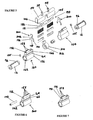
Figure 5 is an exploded perspective view of a third embodiment of the lock body assembly of the invention, including a cap, showing also a second embodiment of the clip of the invention; -
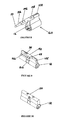
Figure 6 shows in perspective view a stage in production of the lock body assembly ofFigure 5 ; -
Figure 7 shows the next stage in production, after machining of the part of assembly shown inFigure 6 ; -
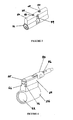
Figure 8 is a perspective view of half of the lock body assembly ofFigure 5 , assembled and in a larger scale; -
Figure 9 is a perspective view of the assembled lock body assembly ofFigures 5 to 8 , without the cap; and -
Figure 10 shows the assembly ofFigure 9 , with the cap. - Referring first to
Figures 1 and2 , the first lock body assembly 10A and secondlock body assembly 10B are shown in the context of a double lock barrel assembly. Each lock barrel assembly includes alock barrel 12 rotatably received in firstmain body 14A and secondmain body 14B. Eachlock barrel 12 has sixpin tumbler passages 16. Whenlock barrel 12 is inserted in place withinmain body 14A ormain body 14B, each ofpin tumbler passages 16 mates with a correspondingpin tumbler passage 18, only one of which can be seen in each ofblock 64. Each ofpin tumbler passages 18 communicates at the lower end withcavity 20 inmain body Upper pin parts 22 and lower pin parts 24 are loaded intopin tumbler passages spring 26, in known manner. - Each
block 64 includesarcuate channel 28. Closing offmeans 30 is designed to slide intoarcuate channel 28 until further travel is prevented byridge 32. In this configuration,bar 34 and flat 40 of closing off means 30 covers the sixpin tumbler passages 18.Aperture 36 lies between the fifth and sixthpin tumbler passage 18 and is eventually secured byscrew 38 as explained below. -
Flat 40 of closing off means 30 is adapted to fit under and mate with flat 42 of connectingmeans 44. In this configuration,aperture 46 lines up withaperture 36. In this way,main body 14A, closing off means 30 and connectingmeans 44 are connected together and secured whenscrew 38 is inserted later (see below). - Likewise,
main body 14B is assembled with closing off means 30 and connectingmeans 44, being secured together by screw 48 (see below) later inserted throughapertures - As shown in
Figure 2 , in the complete assembly,cap 50 is put in place to cover closing off means 30 inarcuate channel 28 and connectingmeans 44.Screw 38 is inserted through aperture 52 incap 50 and then intoapertures Screw 48 is inserted inaperture 54 incap 50 and then intoapertures - The second embodiment is shown in
Figures 3 and4 . This embodiment can be substituted forlock body assemblies 10A and 10B, including closing off means 30 and connectingmeans 44 inFigures 1 and2 .Cap 50 is the same as inFigures 1 and2 . Thesame lock barrel 12, etc, can be used for theFigures 3 and4 embodiment. Although only one lock body is shown inFigures 3 and4 , it is contemplated that an identical lock body will be used for the double lock barrel assembly, as inFigures 1 and2 . - In
Figures 3 and4 , lockbody 60 hasmain body 56 for receipt of a lock barrel (not shown).Lock body 60 includes sixpin tumbler passages 58. Eachpin tumbler passage 58 communicates withcavity 62 at its lower end and is open at its upper end. -
Block 64 includesgrooves 66 andarcuate channel 68.Arcuate channel 68 is considerably more shallow thanarcuate channel 28 ofFigure 1 . - In this embodiment, closing off means 70 has
passageway 72 andarms 74. Eacharm 74 ends intongue 76, adapted to be received ingroove 66. Closing off means 70 can slide ontoblock 64 by engagement oftongues 76 ingrooves 66, as shown inFigure 4 . Thelower part 78 of tube 80 enclosingpassageway 72 closes off the sixpin tumbler passages 58 in this configuration. - To connect to connecting means 90, cylindrical projection 82 of connecting means 90 slides into
passageway 72. Whencap 50 is put in place, a screw inserted through aperture 52 andaperture 86 secures the assembly.Screw 55 is secured to projection 81 of connecting means 90. - The third embodiment is shown in
Figures 5 to 10 .Cap 50 is the same as inFigures 1 and2 and inFigure 3 . Thesame lock barrel 12 is used. - In
Figures 5 to 10 ,lock body 160 hasmain body 156 for receipt oflock barrel 12.Lock body 160 initially includes 6pin tumbler passages 158. Some of these are affected by machining during assembly, as explained in relation toFigure 7 , below. Thepin tumbler passages 158 communicate withcavity 162 at their lower ends and are open at their upper ends. -
Block 164 includes on one side groove 166 (for use in conjunction with clip 200: refer below) and is integrally formed withpassageway 172. In this embodiment, closing off means 170 takes the form of a tubular insert which is inserted inpassageway 172 during manufacture (referFigure 6 ). - To connect to connecting
means 190,cylindrical projection 182 slides intopassageway 172. Whencap 50 is put in place,screw 38 is fastened intoaperture 146 whilescrew 48 is fastened intoaperture 148. -
End 181 ofcylindrical projection 182 contains screw threads (not shown in the figure) to holdnut 155. - As part of manufacture of this embodiment, and with reference to
Figure 6 ,pin tumbler passages 158 are drilled intoblock 164 from above, so that they communicate withcavity 162.Figure 6 shows block 164 before insertion of tubular insert 170. With reference toFigure 7 , after tubular insert 170 is inserted intopassageway 172, so as to close offpin tumbler passages 158, the sub-assembly is machined to cut away part of the top ofblock 164, as shown, to allow assembly of connectingmeans 190. - It will be seen that the third embodiment in
Figures 5 to 10 has two other differences compared to the first embodiment inFigures 1 and2 . In the third embodiment, a second embodiment of clip is shown and the cam assembly is different. These are discussed further below. - Referring now to
Figures 1 and2 , these show a first embodiment ofclip 100. Twoclips 100 are included in the total assembly illustrated. -
Clip 100 is generally "Y" shaped, having first andsecond arms 92 and 94 forming, together withbase 88, slightly more than a semicircle designed to fit intogroove 96 in eachlock barrel 12 whenlock barrel 12 is fully inserted intomain body -
Clip 100 includesprojection 98. Whenlock barrel 12 is inserted inmain body 14B, for example, groove 96 projects beyondmain body 14B andarms 92 and 94 can be inserted ingroove 96 in order to securelock barrel 12 inmain body 14B.Projection 98 can be manipulated to rotateclip 100 so thatprojection 98 is moved up into alignment withblock 64.Projection 98 is held byedge 99 ofcap 50, and also by flat 42 of connectingmeans 44. - When it is desired to remove
lock barrel 12 frommain body 14B,cap 50 is removed. This enablesclip 100 to rotate so thatprojection 98 is free andclip 100 can be pulled away fromgroove 96. In some circumstances it may take a skilled locksmith a significant amount of time to remove a conventional circlip from engagement with a lock barrel. It will be appreciated that the clip of the present invention can greatly expedite disassembly. -
Clip 200 inFigure 5 is also generally "Y" shaped, with first andsecond arms 192 and 194 forming, together with base 188, slightly more than a semicircle, designed to fit intogroove 96 in eachlock barrel 12 when lock barrel is fully inserted intomain body 156. - In this embodiment, in comparison to clip 100 in
Figure 1 ,clip 200 includesflange 202 on projection 198. Projection 198 operates in much the same way asprojection 98 in relation to clip 100 in the first embodiment. However,flange 202 is designed to fit intogroove 166 inblock 164 whenclip 200 is rotated as described in connection withFigure 1 . The fitting offlange 202 intogroove 166 serves to liftclip 200 slightly, to alleviate friction and wear. - Also shown in
Figures 1 and2 is an embodiment of a cam assembly. This hasinner cam part 102, in this embodiment formed of a single part with agroove 104. - The invention, in providing an improved lock body assembly for a double lock barrel assembly, has ready application industrially. The clip provides improvements and efficiencies in connection with the lock body assembly.
Claims (3)
- A lock body assembly (10A; 60; 160) and first lock barrel (12) for a double lock barrel assembly, the lock body assembly (10A; 60; 160) further including:a) a main body (14A; 56; 156) for receipt of the first lock barrel (12); andb) a plurality of pin tumbler passages (18; 58; 158), each communicating at one end with the main body (14A; 56; 156);
whereby:c) said plurality of pin tumbler passages (18; 58; 158) are each open at the other end;
and whereby said lock body assembly (10A; 60; 160) further comprises:d) means (30; 70; 170) for closing off the other end of the pin tumbler passages (18; 58; 158); ande) means (44) for connecting the closing off means (30; 70; 170) with a second closing off means (30; 70; 170) for a second lock body assembly (10B; 60; 160);
and whereby:the lock body assembly (10A 160) is provided with a clip (100; 200) for securing the first lock barrel (12) in the main body (14A; 56: 156); andthe lock barrel (12) includes a peripheral channel (96) adapted to receive the clip (100; 200) when the lock barrel (12) is inserted in the main body (14A; 56; 156), wherein the clip (100; 200) includes an extension (98; 198) for rotating the clip (100; 200) between a first position in which the extension (98; 198) protrudes from the body (14A; 56; 156) and a second position in which the extension (98; 198) does not so protrude. - The lock body assembly (10A; 160) and first lock barrel (12) of claim 1, wherein the clip (100; 200) includes first and second arms (92, 94; 192; 194).
- The lock body assembly (160) and first lock barrel (12) of claim 1 or claim 2, wherein the clip (200) includes a flange (202) adapted to fit into the main body (156).
Applications Claiming Priority (2)
| Application Number | Priority Date | Filing Date | Title |
|---|---|---|---|
| AU2004907154A AU2004907154A0 (en) | 2004-12-16 | Lock Body Assembly, Clip and Cam Assembly | |
| EP05815899A EP1828509A4 (en) | 2004-12-16 | 2005-12-15 | Lock body assembly, clip and cam assembly |
Related Parent Applications (1)
| Application Number | Title | Priority Date | Filing Date |
|---|---|---|---|
| EP05815899A Division EP1828509A4 (en) | 2004-12-16 | 2005-12-15 | Lock body assembly, clip and cam assembly |
Publications (2)
| Publication Number | Publication Date |
|---|---|
| EP2511453A1 EP2511453A1 (en) | 2012-10-17 |
| EP2511453B1 true EP2511453B1 (en) | 2014-09-17 |
Family
ID=36587454
Family Applications (2)
| Application Number | Title | Priority Date | Filing Date |
|---|---|---|---|
| EP20120175620 Expired - Lifetime EP2511453B1 (en) | 2004-12-16 | 2005-12-15 | Clip for securing a lock barrel in a lock body |
| EP05815899A Withdrawn EP1828509A4 (en) | 2004-12-16 | 2005-12-15 | Lock body assembly, clip and cam assembly |
Family Applications After (1)
| Application Number | Title | Priority Date | Filing Date |
|---|---|---|---|
| EP05815899A Withdrawn EP1828509A4 (en) | 2004-12-16 | 2005-12-15 | Lock body assembly, clip and cam assembly |
Country Status (4)
| Country | Link |
|---|---|
| US (1) | US20080087060A1 (en) |
| EP (2) | EP2511453B1 (en) |
| ES (1) | ES2523285T3 (en) |
| WO (1) | WO2006063396A1 (en) |
Families Citing this family (13)
| Publication number | Priority date | Publication date | Assignee | Title |
|---|---|---|---|---|
| AU2006251844B2 (en) * | 2005-05-24 | 2012-07-12 | Austral Lock Pty Ltd | Improvements in lock cylinders |
| WO2006125245A1 (en) * | 2005-05-24 | 2006-11-30 | Watts Hardware Manufacturing Pty Ltd | Improvements in lock cylinders |
| DE502008002279D1 (en) * | 2008-02-14 | 2011-02-24 | Keso Ag | Bridge for connecting the two cylinder halves of a variable-length double lock cylinder |
| CN102278012B (en) * | 2010-06-13 | 2013-08-14 | 优护国际企业股份有限公司 | thin lock |
| EP2989272B1 (en) * | 2013-04-23 | 2017-05-31 | Mauer Locking Systems EOOD | Cylinder lock with a bridge element connecting housing parts |
| CN103711369A (en) * | 2013-05-14 | 2014-04-09 | 徐钜祥 | Improved door lock mechanism |
| CZ305669B6 (en) * | 2014-11-06 | 2016-01-27 | Tokoz A.S. | Coupling for reversible cylinder lock |
| CZ2016442A3 (en) * | 2016-07-18 | 2017-09-13 | Tokoz A.S. | A coupler for a double-sided cylinder lock |
| RU2682875C2 (en) * | 2017-01-09 | 2019-03-21 | Альберт Срапионович Погосян | Cylinder secret mechanism of mortised lock |
| DE102019130742A1 (en) * | 2019-11-14 | 2021-05-20 | Abus Pfaffenhain Gmbh | Profile cylinder |
| CN111155840A (en) * | 2019-12-23 | 2020-05-15 | 胡小平 | Improved structure of single-opening gourd lock cylinder |
| CZ2023281A3 (en) * | 2023-07-24 | 2024-10-23 | Tokoz A.S. | Coupler for two-sided cylinder lock and two-sided cylinder lock with this coupler |
| IT202300019083A1 (en) * | 2023-09-18 | 2025-03-18 | Mottura Serrature Di Sicurezza S P A | MODULAR STRUCTURE LOCKING DEVICE |
Family Cites Families (32)
| Publication number | Priority date | Publication date | Assignee | Title |
|---|---|---|---|---|
| US2877638A (en) * | 1955-06-07 | 1959-03-17 | Independent Lock Co | Pin tumbler lock |
| US3209568A (en) * | 1963-11-27 | 1965-10-05 | Independent Lock Co | Retainer for spring biased tumblers of a cylinder lock |
| US3293892A (en) * | 1964-10-09 | 1966-12-27 | Independent Lock Co | Lock adapter |
| US3429154A (en) * | 1966-10-18 | 1969-02-25 | Taylor Lock Co | Lock plug |
| GB1262651A (en) * | 1968-04-09 | 1972-02-02 | Eaton Yale & Towne | Pin-tumbler locks |
| CH502495A (en) * | 1968-11-30 | 1971-01-31 | Voss Kg J | Cylinder lock |
| FR2232947A5 (en) * | 1973-06-05 | 1975-01-03 | Lammens Jean | |
| CH576576A5 (en) * | 1974-02-14 | 1976-06-15 | Rossetti Charles | |
| US3928991A (en) * | 1974-05-28 | 1975-12-30 | Ray A Gaul | Lock |
| AT348889B (en) * | 1976-04-06 | 1979-03-12 | Winkhaus Fa August | ASYMMETRIC DOUBLE CYLINDER |
| JPS5473436U (en) * | 1977-11-02 | 1979-05-25 | ||
| CH626679A5 (en) * | 1978-05-12 | 1981-11-30 | Ernst Keller | |
| US4215557A (en) * | 1978-09-28 | 1980-08-05 | Emhart Industries, Inc. | Lock with key slot manipulation barrier |
| JPS567113U (en) * | 1979-06-29 | 1981-01-22 | ||
| JPS61182412U (en) * | 1985-05-02 | 1986-11-14 | ||
| DE8526663U1 (en) * | 1985-09-18 | 1985-11-14 | Percic, Mladen, 6000 Frankfurt | Safety lock |
| US4703638A (en) * | 1986-08-25 | 1987-11-03 | Bergstrom Roger E | Removable core lockset with anti-pick core removal ring |
| CA2109872C (en) * | 1993-01-27 | 2004-07-27 | Ernst Keller | Web for a built-in double lock cylinder |
| US5501087A (en) * | 1993-05-27 | 1996-03-26 | Keller; Ernst | Rotary locking cylinder for a safety lock |
| CZ289889B6 (en) * | 1994-03-04 | 2002-04-17 | Ernst Keller | Lock installation |
| US6564601B2 (en) * | 1995-09-29 | 2003-05-20 | Hyatt Jr Richard G | Electromechanical cylinder plug |
| DE19753013A1 (en) * | 1997-12-01 | 1999-06-02 | Mladen Percic | Barrel lock for security purposes |
| US5884512A (en) * | 1997-12-04 | 1999-03-23 | Wayne; Kenneth | Multi-use lock housing and cylinder |
| DE19831510A1 (en) * | 1998-07-14 | 2000-01-20 | Winkhaus Fa August | Profiled lock cylinder has lock bit groove for lock bit provided in corner areas with undercut sections with radius to reduce risk of forced removal of cylinder housing |
| US6105405A (en) * | 1998-11-25 | 2000-08-22 | Wesko Systems Limited | Locking apparatus having a unitary driver |
| FR2797290B1 (en) * | 1999-08-03 | 2001-10-26 | Ct D Approvisionnement En Deco | LOCK CONTROL MECHANISM |
| PL199711B1 (en) * | 2000-01-24 | 2008-10-31 | Ernst Keller | Rotary locking cylinder for a safety lock |
| US6568229B1 (en) * | 2001-02-27 | 2003-05-27 | The Eastern Company | Key operated switch having removable clip retained switch assembly |
| US20030159483A1 (en) * | 2001-11-05 | 2003-08-28 | Kondratuk Michael W. | Rekeyable mortise lock |
| DE20206999U1 (en) * | 2002-05-02 | 2002-08-22 | Bloch, Klaus, 66802 Überherrn | lock cylinder |
| GB2372535B (en) | 2002-06-29 | 2003-04-16 | Security Products Uk Ltd | Lock |
| US20050204790A1 (en) * | 2003-09-29 | 2005-09-22 | Yu Chun T | Lock core structure |
-
2005
- 2005-12-15 EP EP20120175620 patent/EP2511453B1/en not_active Expired - Lifetime
- 2005-12-15 EP EP05815899A patent/EP1828509A4/en not_active Withdrawn
- 2005-12-15 WO PCT/AU2005/001889 patent/WO2006063396A1/en not_active Ceased
- 2005-12-15 ES ES12175620.9T patent/ES2523285T3/en not_active Expired - Lifetime
-
2007
- 2007-06-15 US US11/818,874 patent/US20080087060A1/en not_active Abandoned
Also Published As
| Publication number | Publication date |
|---|---|
| ES2523285T3 (en) | 2014-11-24 |
| US20080087060A1 (en) | 2008-04-17 |
| EP1828509A1 (en) | 2007-09-05 |
| WO2006063396A1 (en) | 2006-06-22 |
| EP1828509A4 (en) | 2011-05-25 |
| EP2511453A1 (en) | 2012-10-17 |
Similar Documents
| Publication | Publication Date | Title |
|---|---|---|
| US20080087060A1 (en) | Lock body assembly, clip and cam assembly | |
| US5722121A (en) | Enclosure hinge | |
| US12281493B2 (en) | Exit trim with simplified lever handing | |
| US5921122A (en) | Device for preventing falling of upper pin tumblers of a lock during change of a lock core in the lock | |
| US8336349B2 (en) | Lock assembly | |
| EP0446566A1 (en) | A universal espagnolette handle for door and window fixtures | |
| US4765163A (en) | Front-loaded knob assembly | |
| US7293332B2 (en) | Device for fastening an extremity of a link to an object | |
| TW200831763A (en) | Lock cylinder with offset pin | |
| US20110072869A1 (en) | Multi-piece plug assembly for a cylinder lock | |
| US11131114B2 (en) | Trim assembly for a door lock and method of assembling a handle thereof | |
| EP1722113B1 (en) | Mechanism for door shackles comprising a sealing ring and method of disassembling such a shackle | |
| EP2333204B1 (en) | Padlock | |
| AU2015246075B2 (en) | A cylinder lock | |
| US20020056299A1 (en) | Switchlock assembly with snap-in cam | |
| US6676178B2 (en) | Door lock assembly having escutcheon with removable posts | |
| MXPA02004586A (en) | Improvements in key operable locks. | |
| US6412319B1 (en) | Lockset having keyed egg-shaped knob | |
| US2135323A (en) | Lock construction | |
| AU711504B2 (en) | Lockset | |
| EP1074772A1 (en) | Ball valve with key-operated lock | |
| EP2762369B1 (en) | Wiper connection seat | |
| AU2007202958A1 (en) | Lock Body Assembly, Clip and Cam Assembly | |
| JPH024989Y2 (en) | ||
| KR20160028130A (en) | The angle of the shaft door lock and hold the manufacturing method and a manufacturing thereby hold shaft angle |
Legal Events
| Date | Code | Title | Description |
|---|---|---|---|
| PUAI | Public reference made under article 153(3) epc to a published international application that has entered the european phase |
Free format text: ORIGINAL CODE: 0009012 |
|
| AC | Divisional application: reference to earlier application |
Ref document number: 1828509 Country of ref document: EP Kind code of ref document: P |
|
| AK | Designated contracting states |
Kind code of ref document: A1 Designated state(s): AT BE BG CH CY CZ DE DK EE ES FI FR GB GR HU IE IS IT LI LT LU LV MC NL PL PT RO SE SI SK TR |
|
| 17P | Request for examination filed |
Effective date: 20130416 |
|
| GRAP | Despatch of communication of intention to grant a patent |
Free format text: ORIGINAL CODE: EPIDOSNIGR1 |
|
| RIC1 | Information provided on ipc code assigned before grant |
Ipc: E05B 27/00 20060101ALN20140319BHEP Ipc: F16B 21/18 20060101ALI20140319BHEP Ipc: E05B 9/10 20060101ALN20140319BHEP Ipc: E05B 9/04 20060101AFI20140319BHEP |
|
| INTG | Intention to grant announced |
Effective date: 20140416 |
|
| GRAS | Grant fee paid |
Free format text: ORIGINAL CODE: EPIDOSNIGR3 |
|
| GRAA | (expected) grant |
Free format text: ORIGINAL CODE: 0009210 |
|
| AC | Divisional application: reference to earlier application |
Ref document number: 1828509 Country of ref document: EP Kind code of ref document: P |
|
| AK | Designated contracting states |
Kind code of ref document: B1 Designated state(s): AT BE BG CH CY CZ DE DK EE ES FI FR GB GR HU IE IS IT LI LT LU LV MC NL PL PT RO SE SI SK TR |
|
| REG | Reference to a national code |
Ref country code: GB Ref legal event code: FG4D |
|
| REG | Reference to a national code |
Ref country code: CH Ref legal event code: EP |
|
| REG | Reference to a national code |
Ref country code: IE Ref legal event code: FG4D |
|
| REG | Reference to a national code |
Ref country code: AT Ref legal event code: REF Ref document number: 687791 Country of ref document: AT Kind code of ref document: T Effective date: 20141015 |
|
| REG | Reference to a national code |
Ref country code: DE Ref legal event code: R096 Ref document number: 602005044768 Country of ref document: DE Effective date: 20141030 |
|
| REG | Reference to a national code |
Ref country code: ES Ref legal event code: FG2A Ref document number: 2523285 Country of ref document: ES Kind code of ref document: T3 Effective date: 20141124 |
|
| REG | Reference to a national code |
Ref country code: NL Ref legal event code: T3 |
|
| PG25 | Lapsed in a contracting state [announced via postgrant information from national office to epo] |
Ref country code: LT Free format text: LAPSE BECAUSE OF FAILURE TO SUBMIT A TRANSLATION OF THE DESCRIPTION OR TO PAY THE FEE WITHIN THE PRESCRIBED TIME-LIMIT Effective date: 20140917 Ref country code: FI Free format text: LAPSE BECAUSE OF FAILURE TO SUBMIT A TRANSLATION OF THE DESCRIPTION OR TO PAY THE FEE WITHIN THE PRESCRIBED TIME-LIMIT Effective date: 20140917 Ref country code: GR Free format text: LAPSE BECAUSE OF FAILURE TO SUBMIT A TRANSLATION OF THE DESCRIPTION OR TO PAY THE FEE WITHIN THE PRESCRIBED TIME-LIMIT Effective date: 20141218 Ref country code: SE Free format text: LAPSE BECAUSE OF FAILURE TO SUBMIT A TRANSLATION OF THE DESCRIPTION OR TO PAY THE FEE WITHIN THE PRESCRIBED TIME-LIMIT Effective date: 20140917 |
|
| REG | Reference to a national code |
Ref country code: LT Ref legal event code: MG4D |
|
| PG25 | Lapsed in a contracting state [announced via postgrant information from national office to epo] |
Ref country code: CY Free format text: LAPSE BECAUSE OF FAILURE TO SUBMIT A TRANSLATION OF THE DESCRIPTION OR TO PAY THE FEE WITHIN THE PRESCRIBED TIME-LIMIT Effective date: 20140917 Ref country code: LV Free format text: LAPSE BECAUSE OF FAILURE TO SUBMIT A TRANSLATION OF THE DESCRIPTION OR TO PAY THE FEE WITHIN THE PRESCRIBED TIME-LIMIT Effective date: 20140917 |
|
| REG | Reference to a national code |
Ref country code: AT Ref legal event code: MK05 Ref document number: 687791 Country of ref document: AT Kind code of ref document: T Effective date: 20140917 |
|
| PG25 | Lapsed in a contracting state [announced via postgrant information from national office to epo] |
Ref country code: IS Free format text: LAPSE BECAUSE OF FAILURE TO SUBMIT A TRANSLATION OF THE DESCRIPTION OR TO PAY THE FEE WITHIN THE PRESCRIBED TIME-LIMIT Effective date: 20150117 Ref country code: CZ Free format text: LAPSE BECAUSE OF FAILURE TO SUBMIT A TRANSLATION OF THE DESCRIPTION OR TO PAY THE FEE WITHIN THE PRESCRIBED TIME-LIMIT Effective date: 20140917 Ref country code: EE Free format text: LAPSE BECAUSE OF FAILURE TO SUBMIT A TRANSLATION OF THE DESCRIPTION OR TO PAY THE FEE WITHIN THE PRESCRIBED TIME-LIMIT Effective date: 20140917 Ref country code: SK Free format text: LAPSE BECAUSE OF FAILURE TO SUBMIT A TRANSLATION OF THE DESCRIPTION OR TO PAY THE FEE WITHIN THE PRESCRIBED TIME-LIMIT Effective date: 20140917 Ref country code: RO Free format text: LAPSE BECAUSE OF FAILURE TO SUBMIT A TRANSLATION OF THE DESCRIPTION OR TO PAY THE FEE WITHIN THE PRESCRIBED TIME-LIMIT Effective date: 20140917 Ref country code: PT Free format text: LAPSE BECAUSE OF FAILURE TO SUBMIT A TRANSLATION OF THE DESCRIPTION OR TO PAY THE FEE WITHIN THE PRESCRIBED TIME-LIMIT Effective date: 20150119 |
|
| PG25 | Lapsed in a contracting state [announced via postgrant information from national office to epo] |
Ref country code: PL Free format text: LAPSE BECAUSE OF FAILURE TO SUBMIT A TRANSLATION OF THE DESCRIPTION OR TO PAY THE FEE WITHIN THE PRESCRIBED TIME-LIMIT Effective date: 20140917 Ref country code: AT Free format text: LAPSE BECAUSE OF FAILURE TO SUBMIT A TRANSLATION OF THE DESCRIPTION OR TO PAY THE FEE WITHIN THE PRESCRIBED TIME-LIMIT Effective date: 20140917 |
|
| REG | Reference to a national code |
Ref country code: DE Ref legal event code: R097 Ref document number: 602005044768 Country of ref document: DE |
|
| PG25 | Lapsed in a contracting state [announced via postgrant information from national office to epo] |
Ref country code: BE Free format text: LAPSE BECAUSE OF NON-PAYMENT OF DUE FEES Effective date: 20141231 |
|
| PLBE | No opposition filed within time limit |
Free format text: ORIGINAL CODE: 0009261 |
|
| STAA | Information on the status of an ep patent application or granted ep patent |
Free format text: STATUS: NO OPPOSITION FILED WITHIN TIME LIMIT |
|
| PG25 | Lapsed in a contracting state [announced via postgrant information from national office to epo] |
Ref country code: LU Free format text: LAPSE BECAUSE OF FAILURE TO SUBMIT A TRANSLATION OF THE DESCRIPTION OR TO PAY THE FEE WITHIN THE PRESCRIBED TIME-LIMIT Effective date: 20141215 Ref country code: DK Free format text: LAPSE BECAUSE OF FAILURE TO SUBMIT A TRANSLATION OF THE DESCRIPTION OR TO PAY THE FEE WITHIN THE PRESCRIBED TIME-LIMIT Effective date: 20140917 |
|
| REG | Reference to a national code |
Ref country code: CH Ref legal event code: PL |
|
| 26N | No opposition filed |
Effective date: 20150618 |
|
| REG | Reference to a national code |
Ref country code: IE Ref legal event code: MM4A |
|
| PG25 | Lapsed in a contracting state [announced via postgrant information from national office to epo] |
Ref country code: LI Free format text: LAPSE BECAUSE OF NON-PAYMENT OF DUE FEES Effective date: 20141231 Ref country code: CH Free format text: LAPSE BECAUSE OF NON-PAYMENT OF DUE FEES Effective date: 20141231 Ref country code: IE Free format text: LAPSE BECAUSE OF NON-PAYMENT OF DUE FEES Effective date: 20141215 |
|
| PG25 | Lapsed in a contracting state [announced via postgrant information from national office to epo] |
Ref country code: SI Free format text: LAPSE BECAUSE OF FAILURE TO SUBMIT A TRANSLATION OF THE DESCRIPTION OR TO PAY THE FEE WITHIN THE PRESCRIBED TIME-LIMIT Effective date: 20140917 |
|
| REG | Reference to a national code |
Ref country code: FR Ref legal event code: PLFP Year of fee payment: 11 |
|
| PG25 | Lapsed in a contracting state [announced via postgrant information from national office to epo] |
Ref country code: MC Free format text: LAPSE BECAUSE OF FAILURE TO SUBMIT A TRANSLATION OF THE DESCRIPTION OR TO PAY THE FEE WITHIN THE PRESCRIBED TIME-LIMIT Effective date: 20140917 Ref country code: BG Free format text: LAPSE BECAUSE OF FAILURE TO SUBMIT A TRANSLATION OF THE DESCRIPTION OR TO PAY THE FEE WITHIN THE PRESCRIBED TIME-LIMIT Effective date: 20140917 |
|
| PG25 | Lapsed in a contracting state [announced via postgrant information from national office to epo] |
Ref country code: TR Free format text: LAPSE BECAUSE OF FAILURE TO SUBMIT A TRANSLATION OF THE DESCRIPTION OR TO PAY THE FEE WITHIN THE PRESCRIBED TIME-LIMIT Effective date: 20140917 Ref country code: HU Free format text: LAPSE BECAUSE OF FAILURE TO SUBMIT A TRANSLATION OF THE DESCRIPTION OR TO PAY THE FEE WITHIN THE PRESCRIBED TIME-LIMIT; INVALID AB INITIO Effective date: 20051215 |
|
| REG | Reference to a national code |
Ref country code: FR Ref legal event code: PLFP Year of fee payment: 12 |
|
| PGFP | Annual fee paid to national office [announced via postgrant information from national office to epo] |
Ref country code: NL Payment date: 20161223 Year of fee payment: 12 Ref country code: GB Payment date: 20161228 Year of fee payment: 12 |
|
| PGFP | Annual fee paid to national office [announced via postgrant information from national office to epo] |
Ref country code: FR Payment date: 20161229 Year of fee payment: 12 |
|
| PGFP | Annual fee paid to national office [announced via postgrant information from national office to epo] |
Ref country code: DE Payment date: 20170228 Year of fee payment: 12 |
|
| PGFP | Annual fee paid to national office [announced via postgrant information from national office to epo] |
Ref country code: IT Payment date: 20161223 Year of fee payment: 12 Ref country code: ES Payment date: 20170127 Year of fee payment: 12 |
|
| REG | Reference to a national code |
Ref country code: DE Ref legal event code: R119 Ref document number: 602005044768 Country of ref document: DE |
|
| REG | Reference to a national code |
Ref country code: NL Ref legal event code: MM Effective date: 20180101 |
|
| GBPC | Gb: european patent ceased through non-payment of renewal fee |
Effective date: 20171215 |
|
| PG25 | Lapsed in a contracting state [announced via postgrant information from national office to epo] |
Ref country code: NL Free format text: LAPSE BECAUSE OF NON-PAYMENT OF DUE FEES Effective date: 20180101 |
|
| REG | Reference to a national code |
Ref country code: FR Ref legal event code: ST Effective date: 20180831 |
|
| PG25 | Lapsed in a contracting state [announced via postgrant information from national office to epo] |
Ref country code: DE Free format text: LAPSE BECAUSE OF NON-PAYMENT OF DUE FEES Effective date: 20180703 Ref country code: FR Free format text: LAPSE BECAUSE OF NON-PAYMENT OF DUE FEES Effective date: 20180102 Ref country code: IT Free format text: LAPSE BECAUSE OF NON-PAYMENT OF DUE FEES Effective date: 20171215 |
|
| PG25 | Lapsed in a contracting state [announced via postgrant information from national office to epo] |
Ref country code: GB Free format text: LAPSE BECAUSE OF NON-PAYMENT OF DUE FEES Effective date: 20171215 |
|
| REG | Reference to a national code |
Ref country code: ES Ref legal event code: FD2A Effective date: 20190703 |
|
| PG25 | Lapsed in a contracting state [announced via postgrant information from national office to epo] |
Ref country code: ES Free format text: LAPSE BECAUSE OF NON-PAYMENT OF DUE FEES Effective date: 20171216 |