EP2511074B1 - Method of sealing - Google Patents
Method of sealing Download PDFInfo
- Publication number
- EP2511074B1 EP2511074B1 EP12164201.1A EP12164201A EP2511074B1 EP 2511074 B1 EP2511074 B1 EP 2511074B1 EP 12164201 A EP12164201 A EP 12164201A EP 2511074 B1 EP2511074 B1 EP 2511074B1
- Authority
- EP
- European Patent Office
- Prior art keywords
- light
- housing
- light source
- curable adhesive
- band
- Prior art date
- Legal status (The legal status is an assumption and is not a legal conclusion. Google has not performed a legal analysis and makes no representation as to the accuracy of the status listed.)
- Active
Links
Images


Classifications
-
- B—PERFORMING OPERATIONS; TRANSPORTING
- B29—WORKING OF PLASTICS; WORKING OF SUBSTANCES IN A PLASTIC STATE IN GENERAL
- B29C—SHAPING OR JOINING OF PLASTICS; SHAPING OF MATERIAL IN A PLASTIC STATE, NOT OTHERWISE PROVIDED FOR; AFTER-TREATMENT OF THE SHAPED PRODUCTS, e.g. REPAIRING
- B29C66/00—General aspects of processes or apparatus for joining preformed parts
- B29C66/50—General aspects of joining tubular articles; General aspects of joining long products, i.e. bars or profiled elements; General aspects of joining single elements to tubular articles, hollow articles or bars; General aspects of joining several hollow-preforms to form hollow or tubular articles
- B29C66/51—Joining tubular articles, profiled elements or bars; Joining single elements to tubular articles, hollow articles or bars; Joining several hollow-preforms to form hollow or tubular articles
- B29C66/54—Joining several hollow-preforms, e.g. half-shells, to form hollow articles, e.g. for making balls, containers; Joining several hollow-preforms, e.g. half-cylinders, to form tubular articles
-
- B—PERFORMING OPERATIONS; TRANSPORTING
- B25—HAND TOOLS; PORTABLE POWER-DRIVEN TOOLS; MANIPULATORS
- B25F—COMBINATION OR MULTI-PURPOSE TOOLS NOT OTHERWISE PROVIDED FOR; DETAILS OR COMPONENTS OF PORTABLE POWER-DRIVEN TOOLS NOT PARTICULARLY RELATED TO THE OPERATIONS PERFORMED AND NOT OTHERWISE PROVIDED FOR
- B25F5/00—Details or components of portable power-driven tools not particularly related to the operations performed and not otherwise provided for
- B25F5/02—Construction of casings, bodies or handles
-
- B—PERFORMING OPERATIONS; TRANSPORTING
- B29—WORKING OF PLASTICS; WORKING OF SUBSTANCES IN A PLASTIC STATE IN GENERAL
- B29C—SHAPING OR JOINING OF PLASTICS; SHAPING OF MATERIAL IN A PLASTIC STATE, NOT OTHERWISE PROVIDED FOR; AFTER-TREATMENT OF THE SHAPED PRODUCTS, e.g. REPAIRING
- B29C65/00—Joining or sealing of preformed parts, e.g. welding of plastics materials; Apparatus therefor
- B29C65/02—Joining or sealing of preformed parts, e.g. welding of plastics materials; Apparatus therefor by heating, with or without pressure
- B29C65/14—Joining or sealing of preformed parts, e.g. welding of plastics materials; Apparatus therefor by heating, with or without pressure using wave energy, i.e. electromagnetic radiation, or particle radiation
- B29C65/1429—Joining or sealing of preformed parts, e.g. welding of plastics materials; Apparatus therefor by heating, with or without pressure using wave energy, i.e. electromagnetic radiation, or particle radiation characterised by the way of heating the interface
- B29C65/1435—Joining or sealing of preformed parts, e.g. welding of plastics materials; Apparatus therefor by heating, with or without pressure using wave energy, i.e. electromagnetic radiation, or particle radiation characterised by the way of heating the interface at least passing through one of the parts to be joined, i.e. transmission welding
-
- B—PERFORMING OPERATIONS; TRANSPORTING
- B29—WORKING OF PLASTICS; WORKING OF SUBSTANCES IN A PLASTIC STATE IN GENERAL
- B29C—SHAPING OR JOINING OF PLASTICS; SHAPING OF MATERIAL IN A PLASTIC STATE, NOT OTHERWISE PROVIDED FOR; AFTER-TREATMENT OF THE SHAPED PRODUCTS, e.g. REPAIRING
- B29C65/00—Joining or sealing of preformed parts, e.g. welding of plastics materials; Apparatus therefor
- B29C65/02—Joining or sealing of preformed parts, e.g. welding of plastics materials; Apparatus therefor by heating, with or without pressure
- B29C65/14—Joining or sealing of preformed parts, e.g. welding of plastics materials; Apparatus therefor by heating, with or without pressure using wave energy, i.e. electromagnetic radiation, or particle radiation
- B29C65/1477—Joining or sealing of preformed parts, e.g. welding of plastics materials; Apparatus therefor by heating, with or without pressure using wave energy, i.e. electromagnetic radiation, or particle radiation making use of an absorber or impact modifier
- B29C65/1483—Joining or sealing of preformed parts, e.g. welding of plastics materials; Apparatus therefor by heating, with or without pressure using wave energy, i.e. electromagnetic radiation, or particle radiation making use of an absorber or impact modifier coated on the article
-
- B—PERFORMING OPERATIONS; TRANSPORTING
- B29—WORKING OF PLASTICS; WORKING OF SUBSTANCES IN A PLASTIC STATE IN GENERAL
- B29C—SHAPING OR JOINING OF PLASTICS; SHAPING OF MATERIAL IN A PLASTIC STATE, NOT OTHERWISE PROVIDED FOR; AFTER-TREATMENT OF THE SHAPED PRODUCTS, e.g. REPAIRING
- B29C65/00—Joining or sealing of preformed parts, e.g. welding of plastics materials; Apparatus therefor
- B29C65/48—Joining or sealing of preformed parts, e.g. welding of plastics materials; Apparatus therefor using adhesives, i.e. using supplementary joining material; solvent bonding
- B29C65/4805—Joining or sealing of preformed parts, e.g. welding of plastics materials; Apparatus therefor using adhesives, i.e. using supplementary joining material; solvent bonding characterised by the type of adhesives
- B29C65/483—Reactive adhesives, e.g. chemically curing adhesives
- B29C65/4845—Radiation curing adhesives, e.g. UV light curing adhesives
-
- B—PERFORMING OPERATIONS; TRANSPORTING
- B29—WORKING OF PLASTICS; WORKING OF SUBSTANCES IN A PLASTIC STATE IN GENERAL
- B29C—SHAPING OR JOINING OF PLASTICS; SHAPING OF MATERIAL IN A PLASTIC STATE, NOT OTHERWISE PROVIDED FOR; AFTER-TREATMENT OF THE SHAPED PRODUCTS, e.g. REPAIRING
- B29C65/00—Joining or sealing of preformed parts, e.g. welding of plastics materials; Apparatus therefor
- B29C65/48—Joining or sealing of preformed parts, e.g. welding of plastics materials; Apparatus therefor using adhesives, i.e. using supplementary joining material; solvent bonding
- B29C65/50—Joining or sealing of preformed parts, e.g. welding of plastics materials; Apparatus therefor using adhesives, i.e. using supplementary joining material; solvent bonding using adhesive tape, e.g. thermoplastic tape; using threads or the like
- B29C65/5042—Joining or sealing of preformed parts, e.g. welding of plastics materials; Apparatus therefor using adhesives, i.e. using supplementary joining material; solvent bonding using adhesive tape, e.g. thermoplastic tape; using threads or the like covering both elements to be joined
-
- B—PERFORMING OPERATIONS; TRANSPORTING
- B29—WORKING OF PLASTICS; WORKING OF SUBSTANCES IN A PLASTIC STATE IN GENERAL
- B29C—SHAPING OR JOINING OF PLASTICS; SHAPING OF MATERIAL IN A PLASTIC STATE, NOT OTHERWISE PROVIDED FOR; AFTER-TREATMENT OF THE SHAPED PRODUCTS, e.g. REPAIRING
- B29C66/00—General aspects of processes or apparatus for joining preformed parts
- B29C66/50—General aspects of joining tubular articles; General aspects of joining long products, i.e. bars or profiled elements; General aspects of joining single elements to tubular articles, hollow articles or bars; General aspects of joining several hollow-preforms to form hollow or tubular articles
- B29C66/61—Joining from or joining on the inside
-
- B—PERFORMING OPERATIONS; TRANSPORTING
- B29—WORKING OF PLASTICS; WORKING OF SUBSTANCES IN A PLASTIC STATE IN GENERAL
- B29C—SHAPING OR JOINING OF PLASTICS; SHAPING OF MATERIAL IN A PLASTIC STATE, NOT OTHERWISE PROVIDED FOR; AFTER-TREATMENT OF THE SHAPED PRODUCTS, e.g. REPAIRING
- B29C66/00—General aspects of processes or apparatus for joining preformed parts
- B29C66/70—General aspects of processes or apparatus for joining preformed parts characterised by the composition, physical properties or the structure of the material of the parts to be joined; Joining with non-plastics material
- B29C66/73—General aspects of processes or apparatus for joining preformed parts characterised by the composition, physical properties or the structure of the material of the parts to be joined; Joining with non-plastics material characterised by the intensive physical properties of the material of the parts to be joined, by the optical properties of the material of the parts to be joined, by the extensive physical properties of the parts to be joined, by the state of the material of the parts to be joined or by the material of the parts to be joined being a thermoplastic or a thermoset
- B29C66/733—General aspects of processes or apparatus for joining preformed parts characterised by the composition, physical properties or the structure of the material of the parts to be joined; Joining with non-plastics material characterised by the intensive physical properties of the material of the parts to be joined, by the optical properties of the material of the parts to be joined, by the extensive physical properties of the parts to be joined, by the state of the material of the parts to be joined or by the material of the parts to be joined being a thermoplastic or a thermoset characterised by the optical properties of the material of the parts to be joined, e.g. fluorescence, phosphorescence
- B29C66/7336—General aspects of processes or apparatus for joining preformed parts characterised by the composition, physical properties or the structure of the material of the parts to be joined; Joining with non-plastics material characterised by the intensive physical properties of the material of the parts to be joined, by the optical properties of the material of the parts to be joined, by the extensive physical properties of the parts to be joined, by the state of the material of the parts to be joined or by the material of the parts to be joined being a thermoplastic or a thermoset characterised by the optical properties of the material of the parts to be joined, e.g. fluorescence, phosphorescence at least one of the parts to be joined being opaque, transparent or translucent to visible light
- B29C66/73361—General aspects of processes or apparatus for joining preformed parts characterised by the composition, physical properties or the structure of the material of the parts to be joined; Joining with non-plastics material characterised by the intensive physical properties of the material of the parts to be joined, by the optical properties of the material of the parts to be joined, by the extensive physical properties of the parts to be joined, by the state of the material of the parts to be joined or by the material of the parts to be joined being a thermoplastic or a thermoset characterised by the optical properties of the material of the parts to be joined, e.g. fluorescence, phosphorescence at least one of the parts to be joined being opaque, transparent or translucent to visible light at least one of the parts to be joined being opaque to visible light
-
- B—PERFORMING OPERATIONS; TRANSPORTING
- B29—WORKING OF PLASTICS; WORKING OF SUBSTANCES IN A PLASTIC STATE IN GENERAL
- B29C—SHAPING OR JOINING OF PLASTICS; SHAPING OF MATERIAL IN A PLASTIC STATE, NOT OTHERWISE PROVIDED FOR; AFTER-TREATMENT OF THE SHAPED PRODUCTS, e.g. REPAIRING
- B29C65/00—Joining or sealing of preformed parts, e.g. welding of plastics materials; Apparatus therefor
- B29C65/02—Joining or sealing of preformed parts, e.g. welding of plastics materials; Apparatus therefor by heating, with or without pressure
- B29C65/14—Joining or sealing of preformed parts, e.g. welding of plastics materials; Apparatus therefor by heating, with or without pressure using wave energy, i.e. electromagnetic radiation, or particle radiation
- B29C65/1403—Joining or sealing of preformed parts, e.g. welding of plastics materials; Apparatus therefor by heating, with or without pressure using wave energy, i.e. electromagnetic radiation, or particle radiation characterised by the type of electromagnetic or particle radiation
- B29C65/1406—Ultraviolet [UV] radiation
-
- B—PERFORMING OPERATIONS; TRANSPORTING
- B29—WORKING OF PLASTICS; WORKING OF SUBSTANCES IN A PLASTIC STATE IN GENERAL
- B29C—SHAPING OR JOINING OF PLASTICS; SHAPING OF MATERIAL IN A PLASTIC STATE, NOT OTHERWISE PROVIDED FOR; AFTER-TREATMENT OF THE SHAPED PRODUCTS, e.g. REPAIRING
- B29C65/00—Joining or sealing of preformed parts, e.g. welding of plastics materials; Apparatus therefor
- B29C65/02—Joining or sealing of preformed parts, e.g. welding of plastics materials; Apparatus therefor by heating, with or without pressure
- B29C65/14—Joining or sealing of preformed parts, e.g. welding of plastics materials; Apparatus therefor by heating, with or without pressure using wave energy, i.e. electromagnetic radiation, or particle radiation
- B29C65/1403—Joining or sealing of preformed parts, e.g. welding of plastics materials; Apparatus therefor by heating, with or without pressure using wave energy, i.e. electromagnetic radiation, or particle radiation characterised by the type of electromagnetic or particle radiation
- B29C65/1409—Visible light radiation
-
- B—PERFORMING OPERATIONS; TRANSPORTING
- B29—WORKING OF PLASTICS; WORKING OF SUBSTANCES IN A PLASTIC STATE IN GENERAL
- B29C—SHAPING OR JOINING OF PLASTICS; SHAPING OF MATERIAL IN A PLASTIC STATE, NOT OTHERWISE PROVIDED FOR; AFTER-TREATMENT OF THE SHAPED PRODUCTS, e.g. REPAIRING
- B29C65/00—Joining or sealing of preformed parts, e.g. welding of plastics materials; Apparatus therefor
- B29C65/48—Joining or sealing of preformed parts, e.g. welding of plastics materials; Apparatus therefor using adhesives, i.e. using supplementary joining material; solvent bonding
- B29C65/50—Joining or sealing of preformed parts, e.g. welding of plastics materials; Apparatus therefor using adhesives, i.e. using supplementary joining material; solvent bonding using adhesive tape, e.g. thermoplastic tape; using threads or the like
- B29C65/5092—Joining or sealing of preformed parts, e.g. welding of plastics materials; Apparatus therefor using adhesives, i.e. using supplementary joining material; solvent bonding using adhesive tape, e.g. thermoplastic tape; using threads or the like characterised by the tape handling mechanisms, e.g. using vacuum
-
- B—PERFORMING OPERATIONS; TRANSPORTING
- B29—WORKING OF PLASTICS; WORKING OF SUBSTANCES IN A PLASTIC STATE IN GENERAL
- B29C—SHAPING OR JOINING OF PLASTICS; SHAPING OF MATERIAL IN A PLASTIC STATE, NOT OTHERWISE PROVIDED FOR; AFTER-TREATMENT OF THE SHAPED PRODUCTS, e.g. REPAIRING
- B29C66/00—General aspects of processes or apparatus for joining preformed parts
- B29C66/001—Joining in special atmospheres
- B29C66/0012—Joining in special atmospheres characterised by the type of environment
- B29C66/0014—Gaseous environments
- B29C66/00141—Protective gases
-
- B—PERFORMING OPERATIONS; TRANSPORTING
- B29—WORKING OF PLASTICS; WORKING OF SUBSTANCES IN A PLASTIC STATE IN GENERAL
- B29C—SHAPING OR JOINING OF PLASTICS; SHAPING OF MATERIAL IN A PLASTIC STATE, NOT OTHERWISE PROVIDED FOR; AFTER-TREATMENT OF THE SHAPED PRODUCTS, e.g. REPAIRING
- B29C66/00—General aspects of processes or apparatus for joining preformed parts
- B29C66/70—General aspects of processes or apparatus for joining preformed parts characterised by the composition, physical properties or the structure of the material of the parts to be joined; Joining with non-plastics material
- B29C66/71—General aspects of processes or apparatus for joining preformed parts characterised by the composition, physical properties or the structure of the material of the parts to be joined; Joining with non-plastics material characterised by the composition of the plastics material of the parts to be joined
-
- B—PERFORMING OPERATIONS; TRANSPORTING
- B29—WORKING OF PLASTICS; WORKING OF SUBSTANCES IN A PLASTIC STATE IN GENERAL
- B29C—SHAPING OR JOINING OF PLASTICS; SHAPING OF MATERIAL IN A PLASTIC STATE, NOT OTHERWISE PROVIDED FOR; AFTER-TREATMENT OF THE SHAPED PRODUCTS, e.g. REPAIRING
- B29C66/00—General aspects of processes or apparatus for joining preformed parts
- B29C66/70—General aspects of processes or apparatus for joining preformed parts characterised by the composition, physical properties or the structure of the material of the parts to be joined; Joining with non-plastics material
- B29C66/73—General aspects of processes or apparatus for joining preformed parts characterised by the composition, physical properties or the structure of the material of the parts to be joined; Joining with non-plastics material characterised by the intensive physical properties of the material of the parts to be joined, by the optical properties of the material of the parts to be joined, by the extensive physical properties of the parts to be joined, by the state of the material of the parts to be joined or by the material of the parts to be joined being a thermoplastic or a thermoset
- B29C66/733—General aspects of processes or apparatus for joining preformed parts characterised by the composition, physical properties or the structure of the material of the parts to be joined; Joining with non-plastics material characterised by the intensive physical properties of the material of the parts to be joined, by the optical properties of the material of the parts to be joined, by the extensive physical properties of the parts to be joined, by the state of the material of the parts to be joined or by the material of the parts to be joined being a thermoplastic or a thermoset characterised by the optical properties of the material of the parts to be joined, e.g. fluorescence, phosphorescence
- B29C66/7336—General aspects of processes or apparatus for joining preformed parts characterised by the composition, physical properties or the structure of the material of the parts to be joined; Joining with non-plastics material characterised by the intensive physical properties of the material of the parts to be joined, by the optical properties of the material of the parts to be joined, by the extensive physical properties of the parts to be joined, by the state of the material of the parts to be joined or by the material of the parts to be joined being a thermoplastic or a thermoset characterised by the optical properties of the material of the parts to be joined, e.g. fluorescence, phosphorescence at least one of the parts to be joined being opaque, transparent or translucent to visible light
- B29C66/73365—General aspects of processes or apparatus for joining preformed parts characterised by the composition, physical properties or the structure of the material of the parts to be joined; Joining with non-plastics material characterised by the intensive physical properties of the material of the parts to be joined, by the optical properties of the material of the parts to be joined, by the extensive physical properties of the parts to be joined, by the state of the material of the parts to be joined or by the material of the parts to be joined being a thermoplastic or a thermoset characterised by the optical properties of the material of the parts to be joined, e.g. fluorescence, phosphorescence at least one of the parts to be joined being opaque, transparent or translucent to visible light at least one of the parts to be joined being transparent or translucent to visible light
-
- B—PERFORMING OPERATIONS; TRANSPORTING
- B29—WORKING OF PLASTICS; WORKING OF SUBSTANCES IN A PLASTIC STATE IN GENERAL
- B29K—INDEXING SCHEME ASSOCIATED WITH SUBCLASSES B29B, B29C OR B29D, RELATING TO MOULDING MATERIALS OR TO MATERIALS FOR MOULDS, REINFORCEMENTS, FILLERS OR PREFORMED PARTS, e.g. INSERTS
- B29K2995/00—Properties of moulding materials, reinforcements, fillers, preformed parts or moulds
- B29K2995/0018—Properties of moulding materials, reinforcements, fillers, preformed parts or moulds having particular optical properties, e.g. fluorescent or phosphorescent
- B29K2995/0026—Transparent
- B29K2995/0027—Transparent for light outside the visible spectrum
-
- B—PERFORMING OPERATIONS; TRANSPORTING
- B29—WORKING OF PLASTICS; WORKING OF SUBSTANCES IN A PLASTIC STATE IN GENERAL
- B29L—INDEXING SCHEME ASSOCIATED WITH SUBCLASS B29C, RELATING TO PARTICULAR ARTICLES
- B29L2031/00—Other particular articles
- B29L2031/28—Tools, e.g. cutlery
- B29L2031/283—Hand tools
-
- B—PERFORMING OPERATIONS; TRANSPORTING
- B29—WORKING OF PLASTICS; WORKING OF SUBSTANCES IN A PLASTIC STATE IN GENERAL
- B29L—INDEXING SCHEME ASSOCIATED WITH SUBCLASS B29C, RELATING TO PARTICULAR ARTICLES
- B29L2031/00—Other particular articles
- B29L2031/34—Electrical apparatus, e.g. sparking plugs or parts thereof
- B29L2031/3481—Housings or casings incorporating or embedding electric or electronic elements
-
- B—PERFORMING OPERATIONS; TRANSPORTING
- B29—WORKING OF PLASTICS; WORKING OF SUBSTANCES IN A PLASTIC STATE IN GENERAL
- B29L—INDEXING SCHEME ASSOCIATED WITH SUBCLASS B29C, RELATING TO PARTICULAR ARTICLES
- B29L2031/00—Other particular articles
- B29L2031/46—Knobs or handles, push-buttons, grips
- B29L2031/463—Grips, handles
Definitions
- the present invention lies in the field of sealing.
- the present disclosure relates to a method of sealing that uses a light curable adhesive to attach enclosure parts together.
- Devices having a mechanical housing or enclosure are typically formed from two or more parts attached together to enclose therein mechanical or electrical components that allow the device to function.
- Various examples of different ways of attaching multi-part enclosures include:
- This seal is at least gas-tight, thereby preventing intrusion of air, water, vapor phase H 2 O 2 , etc.
- This gas-tight construction of the battery assembly allows it to be sterilized, for example, using low-temperature vapor phase Hydrogen Peroxide (H 2 O 2 ) as performed by the sterilization devices manufactured by the Steris Corporation and referred to under the trade name V-PRO or manufactured by Advanced Sterilization Products (ASP), division of Ethicon, Inc., a Johnson & Johnson company, and referred to under the trade name STERRAD®.
- H 2 O 2 sterilization devices manufactured by the Steris Corporation and referred to under the trade name V-PRO or manufactured by Advanced Sterilization Products (ASP), division of Ethicon, Inc., a Johnson & Johnson company, and referred to under the trade name STERRAD®.
- the hermetic seal formed by the ultrasonic welding of the battery assembly described above advantageously allows sterilization of the battery assembly, maintenance of the hermetic seal, and thus preservation of the components housed within the battery assembly, could decrease over time.
- the invention is defined by appended set of claims and provides a method of sealing that overcome the hereinafore-mentioned disadvantages of the heretofore-known devices and methods of this general type.
- a method for creating a seal including the steps of providing a structure comprised of at least two adjacent parts forming an enclosure and having a contact surface therebetween, at least one part of the structure being comprised of a material that appears substantially opaque to the naked eye and is substantially transparent to light, applying a light-curable adhesive at the contact surface, and transmitting light to cure the light-curable adhesive to form a hermetic seal at the contact surface between the at least two adjacent parts,
- a method for creating a seal including the steps of providing a structure comprised of at least first and second housing portions having first and second contact surfaces, respectively and a band comprised of a material that is substantially transparent to light, the band being disposed between the first and second housing portions at the first and second contact surfaces to form an enclosure together with the first and second housing portions, applying a light-curable adhesive at the first and second contact surfaces between the band and the first and second housing portions, and transmitting light to cure the light-curable adhesive to form a hermetic seal at the first and second contact surfaces between the band and the first and second housing portions.
- a method for creating a seal Including the steps of providing a multi-part structure comprised of adjacent parts that form an enclosure and have a contact surface therebetween, disposing at least one light source inside the enclosure, applying a light-curable adhesive at the contact surface, and powering the at least one light source to transmit light sufficient to cure the light-curable adhesive from inside the enclosure and, thereby, form a hermetic seal at the contact surface between the adjacent parts.
- the light cures the light-curable adhesive by being transmitted through the at least one part of the structure that is both substantially opaque to the naked eye and substantially transparent to light.
- the at least one part of the structure that is both substantially opaque to the naked eye and substantially transparent to light is transparent to ultraviolet light
- the light-curable adhesive is curable by ultraviolet light
- the transmitted light is ultraviolet light
- the at least one part of the structure that is both substantially opaque to the naked eye and substantially transparent to light is transparent to visible light
- the light-curable adhesive is curable by visible light
- the transmitted light is visible light
- the at least one part of the structure that is both substantially opaque to the naked eye and substantially transparent to light is comprised of a transparent polymeric material.
- the step of adding at least one of a light-transmissive agent to the transparent polymeric material to cause the transparent polymeric material to have an opaque appearance to the naked eye and a diffusing agent to the transparent polymeric material to disperse the transmitted light along the contact surface for curing the light-curable adhesive is provided.
- forming a closed enclosure by placing the at least two adjacent parts of the structure together at the contact surface.
- the structure further comprises a band comprised of a material that is substantially transparent to light, the band being disposed between the at least first and second housing portions at the contact surface to form an enclosure together with the first and second housing portions.
- the light cures the light-curable adhesive by being transmitted through the band.
- the band is transparent to ultraviolet light
- the light-curable adhesive is curable by ultraviolet light
- the transmitted light is ultraviolet light
- the band is transparent to visible light
- the light-curable adhesive is curable by visible light
- the transmitted light is visible light
- the band appears substantially opaque to the naked eye.
- the step of adding at least one of a light-transmissive agent to the band to cause it to have an opaque appearance to the naked eye and a diffusing agent to the band to disperse the transmitted light along the at least one contact surface for curing the light-curable adhesive is provided.
- a circuit board is provided within the enclosure and the at least one light source is disposed on the circuit board, the circuit board being operable to cause the at least one light source to transmit the light sufficient to cure the light-curable adhesive.
- the at least one light source is at least one ultraviolet light source and the light-curable adhesive is curable by ultraviolet light.
- the at least one light source is a plurality of ultraviolet light-emitting diodes.
- the at least one light source is at least one visible light source and the light-curable adhesive is curable by visible light.
- Relational terms such as first and second, top and bottom, and the like may be used solely to distinguish one entity or action from another entity or action without necessarily requiring or implying any actual such relationship or order between such entities or actions.
- the terms "comprises,” “comprising,” or any other variation thereof are intended to cover a non-exclusive inclusion, such that a process, method, article, or apparatus that comprises a list of elements does not include only those elements but may include other elements not expressly listed or inherent to such process, method, article, or apparatus.
- An element proceeded by "comprises ... a" does not, without more constraints, preclude the existence of additional identical elements in the process, method, article, or apparatus that comprises the element.
- the term “about” or “approximately” applies to all numeric values, whether or not explicitly indicated. These terms generally refer to a range of numbers that one of skill in the art would consider equivalent to the recited values (i.e., having the same function or result). In many instances these terms may include numbers that are rounded to the nearest significant figure.
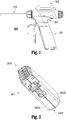
- the assembly 300 includes three main component parts: (1) a battery assembly 301; (2) a handle assembly 302 with an ultrasonic-cutting-blade-and-waveguide assembly 304; and (3) a transducer-and-generator (“TAG”) assembly 303.
- a battery assembly 301 (2) a handle assembly 302 with an ultrasonic-cutting-blade-and-waveguide assembly 304; and (3) a transducer-and-generator (“TAG”) assembly 303.
- TAG transducer-and-generator
- FIG. 2 shows the fully assembled battery assembly 301, which has been ultrasonically welded so that the two halves 2802a and 2802b of the outer shell 2802, as well as the potted multi-lead battery terminal assembly 2804, provide a hermetic seal between the environment and the interior of the battery assembly 301.
- Exemplary embodiments of the present invention provide inventive methods for sealing multi-part housings of similar battery and TAG assemblies.
- the disclosed embodiments are merely exemplary of the invention, which can be embodied in various devices having a mechanical housing or enclosure formed from two or more parts attached together to enclose therein various mechanical or electrical components.
- Some exemplary devices include laparoscopic cameras, rigid endoscopes, and other enclosure devices or devices that are not necessarily enclosure devices, e.g., laparoscopic or other mechanical hand tools.
- a “hermetic" seal indicates a seal that sufficiently isolates a compartment (e.g., an interior of a shell) and components disposed therein from a sterile field of an operating environment into which the device has been introduced so that no contaminants from one side of the seal are able to transfer to the other side of the seal.
- This seal is at least gas-tight, thereby preventing intrusion of air, water, vapor phase H 2 O 2 , etc.
- room air will be trapped in the enclosure with whatever moisture is present. This can easily be more moisture than is desirable in an electronics enclosure. Therefore, in an exemplary embodiment, inclusion of a desiccant system inside the enclosure is desirable and can serve two purposes.
- a primary purpose is to absorb any moisture that may ingress over the life of the device, but, if sized appropriately, the desiccant system will also serve to absorb any moisture that is trapped during assembly. Use of the desiccant system, therefore, simplifies assembly and eliminates the need to close the enclosure under any special environments.
- the battery assembly 110 includes an outer shell or housing 112 comprising a first portion 112a and a second portion 112b.
- the first and second portions 112a and 112b are first and second halves of the outer shell or housing 112.
- the housing 112 may be comprised of more than two sub-parts of differing portions.
- the first and second housing portions 112a and 112b are attached together to enclose therein mechanical and electrical components (not shown) that allow the device, to which the battery assembly 110 supplies power, to function.
- An ultraviolet (UV) light-curable or visible-light curable adhesive is used to attach the housing portions 112a, 112b together.
- the first and second housing portions 112a, 112b have a contact surface 114 therebetween and the adhesive is applied at one or both opposing sides of the contact surface 114 to provide a hermetic seal between first and second housing portions 112a and 112b.
- the adhesive is not easily depicted in the drawings and, therefore, it is not shown.
- the adhesive is disposed between the first and second housing portions 112a and 112b along the contact surface 114 therebetween.
- each of the first and second housing portions 112a and 112b is formed from a material that appears opaque to the naked eye, but is light transparent.
- the housing 112 is transmissive to light to allow for curing of the adhesive to seal the two housing portions 112a, 112b together, but it is not transmissive enough to allow visibility by the naked eye therethrough.
- the terms "substantially opaque” and “substantially transparent” are respectively defined as characterizing a material that appears opaque to the naked eye, and yet, allows at least a portion of the light spectrum to be transmitted therethrough.
- UV light having a wavelength between about 320 and about 390 nm
- visible light having a wavelength between about 435 and about 500 nm
- FIG. 4 illustrates another exemplary battery assembly 210, which is similar to the battery assembly 110 of FIG. 3 and, therefore, similar reference numbers increased by 100 refer to similar parts.
- the battery assembly 210 includes a spacer band 220 disposed between the first and second housing portions 212a and 212b.
- a light-curable adhesive is used to attach the housing portions 212a, 212b and the band 220 together.
- the first housing portion 212a and the band 220 have a contact surface 214a therebetween
- the second housing portion 212b and the band 220 have a contact surface 214b therebetween.
- the adhesive is applied at the contact surfaces 214a, 214b to provide a hermetic seal between the three parts 212a, 212b, 220 to collectively form the housing 212 in FIG. 4 .
- the adhesive is disposed between the first and second housing portions 212a and 212b and the band 220 along the contact surfaces 214a, 214b therebetween.
- the band 220 is formed from a material that is light transparent to allow for curing of the adhesive to seal the two housing portions 212a, 212b and the band 220 together.
- the material may be the same as that used to make the housing portions 112a, 112b of FIG. 3 , i.e., visibly opaque but transmissive to light.
- the band 220 since the band 220 makes up a much smaller portion of the housing 212 relative to the first and second portions 212a, 212b, the band 220 may be formed of a material that is both light transparent and visibly transparent. In such configuration, most of the components enclosed within the interior of the housing 212 would remain substantially concealed by the housing portions 212a, 212b.
- the housing portions 212a, 212b of FIG. 4 may or may not be formed of the same material as the housing portions 112a, 112b in FIG. 3 .
- the housing portions 212a, 212b it is not necessary for the housing portions 212a, 212b to be light transparent in this exemplary embodiment because light is already able to transmit through the band 220 to cure the adhesive.
- UV light having a wavelength between about 320 and about 390 nm
- visible light having a wavelength between about 435 and about 500 nm
- the housing portions 212a, 212b need not be transparent to this light.
- Fillers for modifying properties of the housing portions e.g., lubricity, stiffness, flame rating, RF blocking, can be used to create the opacity.
- FIG. 5 illustrates an exemplary configuration of internal components of a battery assembly 410.
- the housing is not shown but may be similar to either of the housings 112, 212 in FIGS. 3 or 4 .
- the material from which the housing is made is not relevant for purposes of curing the adhesive, whether it be visibly opaque, but transmissive to light, or entirely non-transmissive to light in this exemplary embodiment. This is because the light curable adhesive, in this exemplary configuration, is cured from the inside of the housing to provide a hermetic seal between the housing portions.
- a plurality of light emitting diodes (LEDs) 424 may be disposed on one or more of the circuit boards 426 housed within the interior of the housing.
- LEDs light emitting diodes
- Such LEDs are operable to transmit UV light (with a wavelength between about 320 and about 390 nm) or visible light (with a wavelength between about 435 and about 500 nm) sufficient to cure the adhesive and seal the housing portions together.
- the curing, i.e., operation of the LEDs may occur, for example, during the manufacturing process.
- the LEDs can be disposed around an edge of the circuit board to illuminate evenly across the entire joint. When cured during the manufacturing process, the manufacturer is able to test the viability of the seal prior to shipment of the manufactured device.
- FIGS. 6 and 7 additional embodiments depicting exemplary sealed devices and exemplary sealing methods are shown, this time using a transducer-and-generator ("TAG") assembly similar to the TAG assembly 303 within the device shown in FIG. 1 .
- TAG transducer-and-generator
- the exemplary embodiment of the TAG assembly 510 in FIG. 6 has a two-part housing 512, including first and second housing portions 512a, 512b, attached together to enclose therein mechanical and electrical components (not shown).
- a UV or visible light-curable adhesive is used to attach the housing portions 512a, 512b together.
- the first and second housing portions 512a, 512b have a contact surface 514 therebetween, and the adhesive is applied at the contact surface 514 to provide a hermetic seal between the first and second housing portions 512a, 512b.
- the adhesive is disposed between the first and second housing portions 512a and 512b along at least one half of the contact surface 514 therebetween.
- each of the first and second housing portions 512a, 512b is formed from a material that appears opaque, but is light transparent.
- at least a portion of the housing 512 is transmissive to light to allow for curing of the adhesive to seal the two housing portions 512a, 512b together, but it is not transmissive enough to allow visibility therethrough.
- UV light having a wavelength between about 320 and about 390 nm
- visible light having a wavelength between about 435 and about 500 nm
- the TAG assembly 610 is similar to the TAG assembly 510 of FIG. 6 , wherein similar reference numbers increased by 100 refer to similar parts.
- the TAG assembly 610 includes a spacer band 620 disposed between the first and second housing portions 612a and 612b.
- a light-curable adhesive is used to attach the housing portions 612a, 612b and the band 620 together.
- the first housing portion 612a and the band 620 have a contact surface 614a therebetween
- the second housing portion 612b and the band 620 have a contact surface 614b therebetween.
- the adhesive is applied at the contact surfaces 614a, 614b to provide a hermetic seal between the three parts 612a, 612b, 620 to collectively form the housing 612 in FIG. 7 .
- the adhesive is disposed between the first and second housing portions 612a and 612b and the band 620 along the contact surfaces 614a, 614b therebetween.
- the band 620 is formed from a material that is light transparent to allow for curing of the adhesive to seal the two housing portions 612a, 612b and the band 620 together.
- the material may be the same as that used to make the housing portions 512a, 512b of FIG.6 , i.e., visibly opaque but transmissive to light.
- the band 620 since the band 620 makes up a much smaller portion of the housing 612 relative to the first and second portions 612a, 612b, the band 620 may be formed of a material that is both light transparent and visibly transparent. In such configuration, most of the components enclosed within the interior of the housing 612 would remain substantially concealed by the housing portions 612a, 612b.
- the housing portions 612a, 612b of FIG. 7 may or may not be formed of the same material as the housing portions 512a, 512b in FIG. 6 .
- UV light having a wavelength between about 320 and about 390 nm
- visible light having a wavelength between about 435 and about 500 nm
- a TAG assembly may include a two-part housing that is sealed by a light-curable adhesive that is cured from within the housing.
- the housing may include one or more circuit boards enclosed therein with one or more UV LEDs disposed thereon and operable to transmit UV light (with a wavelength between about 320 and about 390 nm) or visible light (a wavelength between about 435 and about 500 nm) sufficient to cure the adhesive and provide a hermetic seal between the housing sub-parts.
- the material from which the housing is made is not relevant for purposes of curing the adhesive, whether it be visibly opaque but transmissive to light or entirely non-transmissive to light.
- colorants can be used to block visible light but allow UV light to pass.
- the material from which the housing portions 112a, 112b, 212a, 212b, 512a, 512b, 612a, 612b, 2802a, 2802b and bands 220, 620 are formed includes a transparent polymer, e.g., polycarbonate, polysulfone, acrylic, polyethylene terephthalate (PET), or transparent nylons.
- a transparent polymer e.g., polycarbonate, polysulfone, acrylic, polyethylene terephthalate (PET), or transparent nylons.
- Tinting agents, diffusing agents, or other filler materials e.g., any combination of glass, minerals, mica, and talc, are added to the transparent polymer to create a cloudy opaque appearance, yet maintain the ability to transmit UV or visible light therethrough.
- Diffusing agents added to the polymer material may also serve as a light guide to help disperse the light during curing of the light-curable adhesive.
- housing portions 112a, 112b, 212a, 212b, 512a, 512b, 612a, 612b, 2802a, 2802b and bands 220, 620 may be comprised of a transparent polycarbonate material that has been subsequently tinted with a tint based on a particular PANTONE® color number.
- a diffusing agent having Carbon Black among its constituents could be subsequently added to the polycarbonate base material.
- the light-curable adhesive is a UV or visible light curable adhesive, e.g., DYMAX®, LOCTITE®, or any other suitable light-curable adhesive known by one of ordinary skill in the art.
- the light-curable adhesive provides advantages over other adhesives, e.g., two-part epoxy/urethane adhesives, which release free gases that corrode or degrade the polymer of the housing or circuits contained therein. This is especially advantageous for battery assemblies, in which outgassing from an epoxy adhesive, for example, cannot truly be evacuated because subjecting the battery cells to vacuum - to evacuate the outgases from within the battery assembly housing - can degrade or destroy the battery cells.
- the band 220, 620 includes texturizing or lensing (e.g., Fresnel shaping) on an interior surface thereof, which helps reflect the light in all directions within the battery assembly 210 or TAG assembly 610.
- texturizing or lensing e.g., Fresnel shaping
- the band 220, 620 includes tongues configured to mate with corresponding grooves formed in the first and second housing portions 212a, 612a and 212b, 612b (i.e., tongue-in-groove connections) to secure the band 220, 620 to the first and second housing portions.
- the groove edges and/or the tongue can be selectively transparent and/or mirrored so that the curing light reflects and bounces around inside the groove or the housing to enhance curing.
- the adhesive effect is improved by using an inert cover gas that does not react with the photoinitiators in the adhesive.
- the curing may occur in a nitrogen gas environment containing as little oxygen as possible.
- a manufacturing process uses narrow-band light filters to block curing wavelengths of light, but allows non-reactive visible wavelengths of light, in order to inspect parts that are about to be cured.
- a lower intensity reactive visible light may be used to cause a slower cure through a thicker section allowing adhesion at the surface between the adhesive and the substrate before shrinkage of the adhesive can cause delamination from the substrate.
- the outside area can be exposed to UV light for curing.
- the invention also relates to a method for creating a sealed device including the steps of providing a structure comprised of at least two adjacent parts forming an enclosure and having a contact surface therebetween. At least one part of the structure can be comprised of a material that appears substantially opaque to the naked eye and is substantially transparent to light.
- a light-curable adhesive can be applied at the contact surface, and light can be transmitted to cure the light-curable adhesive to form a hermetic seal at the contact surface between the at least two adjacent parts.
Landscapes
- Engineering & Computer Science (AREA)
- Mechanical Engineering (AREA)
- Physics & Mathematics (AREA)
- Health & Medical Sciences (AREA)
- Electromagnetism (AREA)
- Toxicology (AREA)
- Chemical & Material Sciences (AREA)
- Chemical Kinetics & Catalysis (AREA)
- General Chemical & Material Sciences (AREA)
- Battery Mounting, Suspending (AREA)
- Casings For Electric Apparatus (AREA)
- Adhesives Or Adhesive Processes (AREA)
- Lining Or Joining Of Plastics Or The Like (AREA)
Description
- The present invention lies in the field of sealing. The present disclosure relates to a method of sealing that uses a light curable adhesive to attach enclosure parts together.
- Devices having a mechanical housing or enclosure are typically formed from two or more parts attached together to enclose therein mechanical or electrical components that allow the device to function. Various examples of different ways of attaching multi-part enclosures include:
- using any combination of adhesives and mechanical attachment mechanisms, e.g., a-rings,tabs, latches, bolts;
- forming an interference fit between parts, e.g., using friction between two parts to seal the parts together; and
- welding parts together.
- One particular example (disclosed in
U.S. Provisional Patent Application Serial Nos. 61/376,983, filed on August 25, 2010 61/476,022, filed on April 15, 2011 - Although the hermetic seal formed by the ultrasonic welding of the battery assembly described above advantageously allows sterilization of the battery assembly, maintenance of the hermetic seal, and thus preservation of the components housed within the battery assembly, could decrease over time. The combination of H2O2, cleaning chemicals, and disinfecting solution, all used during sterilization, puts stress on the hermetic seal and, therefore, the components within the battery assembly as well.
- Thus, a need exists to overcome any potential for problems with the systems, designs, and processes as discussed above.
- The invention is defined by appended set of claims and provides a method of sealing that overcome the hereinafore-mentioned disadvantages of the heretofore-known devices and methods of this general type.
- With the foregoing and other objects in view, there is provided, in accordance with the invention, a method for creating a seal, including the steps of providing a structure comprised of at least two adjacent parts forming an enclosure and having a contact surface therebetween, at least one part of the structure being comprised of a material that appears substantially opaque to the naked eye and is substantially transparent to light, applying a light-curable adhesive at the contact surface, and transmitting light to cure the light-curable adhesive to form a hermetic seal at the contact surface between the at least two adjacent parts,
- With the foregoing and other objects in view, there is also provided a method for creating a seal including the steps of providing a structure comprised of at least first and second housing portions having first and second contact surfaces, respectively and a band comprised of a material that is substantially transparent to light, the band being disposed between the first and second housing portions at the first and second contact surfaces to form an enclosure together with the first and second housing portions, applying a light-curable adhesive at the first and second contact surfaces between the band and the first and second housing portions, and transmitting light to cure the light-curable adhesive to form a hermetic seal at the first and second contact surfaces between the band and the first and second housing portions.
- With the objects of the invention in view, there is also provided a method for creating a seal, Including the steps of providing a multi-part structure comprised of adjacent parts that form an enclosure and have a contact surface therebetween, disposing at least one light source inside the enclosure, applying a light-curable adhesive at the contact surface, and powering the at least one light source to transmit light sufficient to cure the light-curable adhesive from inside the enclosure and, thereby, form a hermetic seal at the contact surface between the adjacent parts.
- In accordance with another mode of the disclosure, the light cures the light-curable adhesive by being transmitted through the at least one part of the structure that is both substantially opaque to the naked eye and substantially transparent to light.
- In accordance with a further mode of the disclosure, the at least one part of the structure that is both substantially opaque to the naked eye and substantially transparent to light is transparent to ultraviolet light, the light-curable adhesive is curable by ultraviolet light, and the transmitted light is ultraviolet light.
- In accordance with an added mode of the disclosure, the at least one part of the structure that is both substantially opaque to the naked eye and substantially transparent to light is transparent to visible light, the light-curable adhesive is curable by visible light, and the transmitted light is visible light.
- In accordance with an additional mode of the disclosure, the at least one part of the structure that is both substantially opaque to the naked eye and substantially transparent to light is comprised of a transparent polymeric material.
- In accordance with yet another mode of the disclosure, there is provided the step of adding at least one of a light-transmissive agent to the transparent polymeric material to cause the transparent polymeric material to have an opaque appearance to the naked eye and a diffusing agent to the transparent polymeric material to disperse the transmitted light along the contact surface for curing the light-curable adhesive.
- In accordance with yet a further mode of the disclosure, after the applying step and before the transmitting step, forming a closed enclosure by placing the at least two adjacent parts of the structure together at the contact surface.
- In accordance with yet an added mode of the disclosure, the structure further comprises a band comprised of a material that is substantially transparent to light, the band being disposed between the at least first and second housing portions at the contact surface to form an enclosure together with the first and second housing portions.
- In accordance with yet an additional mode of the disclosure, the light cures the light-curable adhesive by being transmitted through the band.
- In accordance with again another mode of the disclosure, the band is transparent to ultraviolet light, the light-curable adhesive is curable by ultraviolet light, and the transmitted light is ultraviolet light.
- In accordance with again a further mode of the disclosure, the band is transparent to visible light, the light-curable adhesive is curable by visible light, and the transmitted light is visible light.
- In accordance with again an added mode of the disclosure, the band appears substantially opaque to the naked eye.
- In accordance with again an additional mode of the disclosure, there is provided the step of adding at least one of a light-transmissive agent to the band to cause it to have an opaque appearance to the naked eye and a diffusing agent to the band to disperse the transmitted light along the at least one contact surface for curing the light-curable adhesive.
- In accordance with still another mode of the invention, there are provided the steps of providing a battery assembly inside the enclosure and electrically coupling the battery assembly to the at least one light source for powering the at least one light source.
- In accordance with still a further mode of the invention, a circuit board is provided within the enclosure and the at least one light source is disposed on the circuit board, the circuit board being operable to cause the at least one light source to transmit the light sufficient to cure the light-curable adhesive.
- In accordance with still an added mode of the invention, the at least one light source is at least one ultraviolet light source and the light-curable adhesive is curable by ultraviolet light. The at least one light source is a plurality of ultraviolet light-emitting diodes.
- In accordance with still an additional mode of the invention, the at least one light source is at least one visible light source and the light-curable adhesive is curable by visible light.
- Although the invention is illustrated and described herein as embodied in a sealed device and method of sealing, it is, nevertheless, not intended to be limited to the details shown because various modifications and structural changes may be made therein without departing from the spirit of the invention and within the scope and range of equivalents of the claims. Additionally, well-known elements of exemplary embodiments of the invention will not be described in detail or will be omitted so as not to obscure the relevant details of the invention.
- The features that are considered as characteristic for the invention are set forth in the appended claims.
- The accompanying figures, where like reference numerals refer to identical or functionally similar elements throughout the separate views, which are not true to scale, and which, together with the detailed description bellow, are incorporated in and form part of the specification, serve to illustrate further various embodiments and to explain various principles and advantages all in accordance with the present invention. Advantages of embodiments of the present invention will be apparent from the following detailed description of the exemplary embodiments thereof, which description should be considered in conjunction with the accompanying drawings in which:
-
FIG. 1 is a fragmentary, left side elevational view of a surgical device having a battery assembly according to an exemplary embodiment of the invention; -
FIG. 2 is a perspective view from above the front of the battery assembly ofFIG. 1 ; -
FIG. 3 is a fragmentary, perspective view of a battery assembly sealed in accordance with an exemplary embodiment of the present invention; -
FIG. 4 is fragmentary, perspective view of a battery assembly sealed in accordance with another exemplary embodiment of the present invention; -
FIG. 5 is a fragmentary perspective view of an exemplary embodiment of internal components within the battery assembly ofFIG. 2 ; -
FIG. 6 is a side perspective view of a transducer-and-generator assembly of the device ofFIG. 1 ; and -
FIG. 7 is a side perspective view of another exemplary embodiment of a transducer-and-generator assembly in accordance with the present invention. - As required, detailed embodiments of the present invention are disclosed herein; however, it is to be understood that the disclosed embodiments are merely exemplary of the invention, which can be embodied in various forms. Therefore, specific structural and functional details disclosed herein are not to be interpreted as limiting, but merely as a basis for the claims and as a representative basis for teaching one skilled in the art to variously employ the present invention in virtually any appropriately detailed structure. Further, the terms and phrases used herein are not intended to be limiting; but rather, to provide an understandable description of the invention. While the specification concludes with claims defining the features of the invention that are regarded as novel, it is believed that the invention will be better understood from a consideration of the following description in conjunction with the drawing figures, in which like reference numerals are carried forward.
- Before the present invention is disclosed and described, it is to be understood that the terminology used herein is for the purpose of describing particular embodiments only and is not intended to be limiting. The terms "a" or "an", as used herein, are defined as one or more than one. The term "plurality," as used herein, is defined as two or more than two. The term "another" as used herein, is defined as at least a second or more. The terms "including" and/or "having," as used herein, are defined as comprising (i.e., open language), The term "coupled," as used herein, is defined as connected, although not necessarily directly, and not necessarily mechanically.
- Relational terms such as first and second, top and bottom, and the like may be used solely to distinguish one entity or action from another entity or action without necessarily requiring or implying any actual such relationship or order between such entities or actions. The terms "comprises," "comprising," or any other variation thereof are intended to cover a non-exclusive inclusion, such that a process, method, article, or apparatus that comprises a list of elements does not include only those elements but may include other elements not expressly listed or inherent to such process, method, article, or apparatus. An element proceeded by "comprises ... a" does not, without more constraints, preclude the existence of additional identical elements in the process, method, article, or apparatus that comprises the element.
- As used herein, the term "about" or "approximately" applies to all numeric values, whether or not explicitly indicated. These terms generally refer to a range of numbers that one of skill in the art would consider equivalent to the recited values (i.e., having the same function or result). In many instances these terms may include numbers that are rounded to the nearest significant figure.
- Herein various embodiments of the present invention are described. In many of the different embodiments, features are similar. Therefore, to avoid redundancy, repetitive description of these similar features may not be made in some circumstances. It shall be understood, however, that description of a first-appearing feature applies to the later described similar feature and each respective description, therefore, is to be incorporated therein without such repetition.
- Referring now to the figures of the drawings in detail and first, particularly to
FIG. 1 , there is shown a first exemplary embodiment of a cordlesssurgical assembly 300, which is described in detail inU.S. Provisional Patent Application Serial Nos. 61/376,983 61/476,022 assembly 300 includes three main component parts: (1) abattery assembly 301; (2) ahandle assembly 302 with an ultrasonic-cutting-blade-and-waveguide assembly 304; and (3) a transducer-and-generator ("TAG")assembly 303. -
FIG. 2 shows the fully assembledbattery assembly 301, which has been ultrasonically welded so that the twohalves outer shell 2802, as well as the potted multi-leadbattery terminal assembly 2804, provide a hermetic seal between the environment and the interior of thebattery assembly 301. Exemplary embodiments of the present invention provide inventive methods for sealing multi-part housings of similar battery and TAG assemblies. However, it is to be understood that the disclosed embodiments are merely exemplary of the invention, which can be embodied in various devices having a mechanical housing or enclosure formed from two or more parts attached together to enclose therein various mechanical or electrical components. Some exemplary devices include laparoscopic cameras, rigid endoscopes, and other enclosure devices or devices that are not necessarily enclosure devices, e.g., laparoscopic or other mechanical hand tools. - A "hermetic" seal, as used herein, indicates a seal that sufficiently isolates a compartment (e.g., an interior of a shell) and components disposed therein from a sterile field of an operating environment into which the device has been introduced so that no contaminants from one side of the seal are able to transfer to the other side of the seal. This seal is at least gas-tight, thereby preventing intrusion of air, water, vapor phase H2O2, etc. Upon initial assembly, room air will be trapped in the enclosure with whatever moisture is present. This can easily be more moisture than is desirable in an electronics enclosure. Therefore, in an exemplary embodiment, inclusion of a desiccant system inside the enclosure is desirable and can serve two purposes. A primary purpose is to absorb any moisture that may ingress over the life of the device, but, if sized appropriately, the desiccant system will also serve to absorb any moisture that is trapped during assembly. Use of the desiccant system, therefore, simplifies assembly and eliminates the need to close the enclosure under any special environments.
- Described now are exemplary embodiments of the present invention. Referring to
FIG. 3 , anexemplary battery assembly 110 is provided. Thebattery assembly 110 includes an outer shell orhousing 112 comprising afirst portion 112a and asecond portion 112b. In this exemplary embodiment, the first andsecond portions housing 112. However, there is no requirement that thehousing 112 be provided in two halves. In fact, thehousing 112 may be comprised of more than two sub-parts of differing portions. The first andsecond housing portions battery assembly 110 supplies power, to function. An ultraviolet (UV) light-curable or visible-light curable adhesive is used to attach thehousing portions second housing portions contact surface 114 therebetween and the adhesive is applied at one or both opposing sides of thecontact surface 114 to provide a hermetic seal between first andsecond housing portions second housing portions contact surface 114 therebetween. - In this exemplary configuration, each of the first and
second housing portions housing 112 is transmissive to light to allow for curing of the adhesive to seal the twohousing portions housing portions housing portions -
FIG. 4 illustrates anotherexemplary battery assembly 210, which is similar to thebattery assembly 110 ofFIG. 3 and, therefore, similar reference numbers increased by 100 refer to similar parts. Thebattery assembly 210, however, includes aspacer band 220 disposed between the first andsecond housing portions housing portions band 220 together. In this exemplary embodiment, thefirst housing portion 212a and theband 220 have acontact surface 214a therebetween, and thesecond housing portion 212b and theband 220 have acontact surface 214b therebetween. The adhesive is applied at thecontact surfaces parts housing 212 inFIG. 4 . Given the location of the adhesive, it is not easily depicted in the drawings and, therefore, is not shown. However, one of ordinary skill in the art would appreciate that the adhesive is disposed between the first andsecond housing portions band 220 along thecontact surfaces - In this exemplary configuration, the
band 220 is formed from a material that is light transparent to allow for curing of the adhesive to seal the twohousing portions band 220 together. The material may be the same as that used to make thehousing portions FIG. 3 , i.e., visibly opaque but transmissive to light. Alternatively, since theband 220 makes up a much smaller portion of thehousing 212 relative to the first andsecond portions band 220 may be formed of a material that is both light transparent and visibly transparent. In such configuration, most of the components enclosed within the interior of thehousing 212 would remain substantially concealed by thehousing portions - The
housing portions FIG. 4 may or may not be formed of the same material as thehousing portions FIG. 3 . In other words, it is not necessary for thehousing portions band 220 to cure the adhesive. Thus, in the exemplary configuration ofFIG. 4 , UV light (having a wavelength between about 320 and about 390 nm) or visible light (having a wavelength between about 435 and about 500 nm) is transmitted through thetransmissive band 220 to cure the adhesive and seal thehousing portions housing portions -
FIG. 5 illustrates an exemplary configuration of internal components of abattery assembly 410. In this exemplary embodiment, the housing is not shown but may be similar to either of thehousings FIGS. 3 or 4 . The material from which the housing is made is not relevant for purposes of curing the adhesive, whether it be visibly opaque, but transmissive to light, or entirely non-transmissive to light in this exemplary embodiment. This is because the light curable adhesive, in this exemplary configuration, is cured from the inside of the housing to provide a hermetic seal between the housing portions. For example, a plurality of light emitting diodes (LEDs) 424, may be disposed on one or more of thecircuit boards 426 housed within the interior of the housing. Such LEDs are operable to transmit UV light (with a wavelength between about 320 and about 390 nm) or visible light (with a wavelength between about 435 and about 500 nm) sufficient to cure the adhesive and seal the housing portions together. The curing, i.e., operation of the LEDs, may occur, for example, during the manufacturing process. In an exemplary configuration, the LEDs can be disposed around an edge of the circuit board to illuminate evenly across the entire joint. When cured during the manufacturing process, the manufacturer is able to test the viability of the seal prior to shipment of the manufactured device. - Referring now to
FIGS. 6 and 7 , additional embodiments depicting exemplary sealed devices and exemplary sealing methods are shown, this time using a transducer-and-generator ("TAG") assembly similar to theTAG assembly 303 within the device shown inFIG. 1 . The exemplary embodiment of theTAG assembly 510 inFIG. 6 has a two-part housing 512, including first andsecond housing portions housing portions second housing portions contact surface 514 therebetween, and the adhesive is applied at thecontact surface 514 to provide a hermetic seal between the first andsecond housing portions second housing portions contact surface 514 therebetween. - In this exemplary embodiment, each of the first and
second housing portions housing 512 is transmissive to light to allow for curing of the adhesive to seal the twohousing portions housing portions housing portions - In
FIG. 7 , theTAG assembly 610 is similar to theTAG assembly 510 ofFIG. 6 , wherein similar reference numbers increased by 100 refer to similar parts. TheTAG assembly 610 includes aspacer band 620 disposed between the first andsecond housing portions housing portions band 620 together. In this exemplary embodiment, thefirst housing portion 612a and theband 620 have acontact surface 614a therebetween, and thesecond housing portion 612b and theband 620 have acontact surface 614b therebetween. The adhesive is applied at thecontact surfaces parts housing 612 inFIG. 7 . Given the location of the adhesive, it is not easily depicted in the drawings and is, therefore, not shown. However, one of ordinary skill in the art would appreciate that the adhesive is disposed between the first andsecond housing portions band 620 along thecontact surfaces - In this exemplary configuration, the
band 620 is formed from a material that is light transparent to allow for curing of the adhesive to seal the twohousing portions band 620 together. The material may be the same as that used to make thehousing portions FIG.6 , i.e., visibly opaque but transmissive to light. Alternatively, since theband 620 makes up a much smaller portion of thehousing 612 relative to the first andsecond portions band 620 may be formed of a material that is both light transparent and visibly transparent. In such configuration, most of the components enclosed within the interior of thehousing 612 would remain substantially concealed by thehousing portions - The
housing portions FIG. 7 may or may not be formed of the same material as thehousing portions FIG. 6 . In other words, it is not necessary for thehousing portions band 620 to cure the adhesive. Thus, in the exemplary configuration ofFIG. 7 , UV light (having a wavelength between about 320 and about 390 nm) or visible light (having a wavelength between about 435 and about 500 nm) is transmitted through thetransmissive band 620 to cure the adhesive and seal thehousing portions - In another exemplary embodiment, a TAG assembly may include a two-part housing that is sealed by a light-curable adhesive that is cured from within the housing. For example, the housing may include one or more circuit boards enclosed therein with one or more UV LEDs disposed thereon and operable to transmit UV light (with a wavelength between about 320 and about 390 nm) or visible light (a wavelength between about 435 and about 500 nm) sufficient to cure the adhesive and provide a hermetic seal between the housing sub-parts. In this exemplary configuration, the material from which the housing is made is not relevant for purposes of curing the adhesive, whether it be visibly opaque but transmissive to light or entirely non-transmissive to light.
- It is noted that the above variations in the battery assemblies can be equally applied to the TAG assembly and, therefore, they are repeated in their entirety herein.
- To make any of the
housing portions - In one exemplary embodiment, where the
housings bands housing portions bands - For example, in accordance with the principles of the present invention,
housing portions bands - The light-curable adhesive is a UV or visible light curable adhesive, e.g., DYMAX®, LOCTITE®, or any other suitable light-curable adhesive known by one of ordinary skill in the art. The light-curable adhesive provides advantages over other adhesives, e.g., two-part epoxy/urethane adhesives, which release free gases that corrode or degrade the polymer of the housing or circuits contained therein. This is especially advantageous for battery assemblies, in which outgassing from an epoxy adhesive, for example, cannot truly be evacuated because subjecting the battery cells to vacuum - to evacuate the outgases from within the battery assembly housing - can degrade or destroy the battery cells.
- In an exemplary embodiment, the
band battery assembly 210 orTAG assembly 610. - In another exemplary embodiment, the
band second housing portions band - In another exemplary embodiment, the adhesive effect is improved by using an inert cover gas that does not react with the photoinitiators in the adhesive. For example, the curing may occur in a nitrogen gas environment containing as little oxygen as possible.
- In another exemplary embodiment, a manufacturing process uses narrow-band light filters to block curing wavelengths of light, but allows non-reactive visible wavelengths of light, in order to inspect parts that are about to be cured.
- In yet another exemplary embodiment, a lower intensity reactive visible light may be used to cause a slower cure through a thicker section allowing adhesion at the surface between the adhesive and the substrate before shrinkage of the adhesive can cause delamination from the substrate.
- If the interior surfaces of the housing parts are painted, and the area of the joint is outside of the opaque, painted boundary, then the outside area can be exposed to UV light for curing.
- The foregoing description and accompanying drawings illustrate the principles, exemplary embodiments, and modes of operation of the invention. However, the invention shall not be construed as being limited to the particular embodiments discussed above. Additional variations of the embodiments discussed above will be appreciated by those skilled in the art and the above-described embodiments shall be regarded as illustrative rather than restrictive. Accordingly, it shall be appreciated that variations to those embodiments can be made by those skilled in the art without departing from the scope of the invention as defined by the following claims.
- Accordingly the invention also relates to a method for creating a sealed device including the steps of providing a structure comprised of at least two adjacent parts forming an enclosure and having a contact surface therebetween. At least one part of the structure can be comprised of a material that appears substantially opaque to the naked eye and is substantially transparent to light. A light-curable adhesive can be applied at the contact surface, and light can be transmitted to cure the light-curable adhesive to form a hermetic seal at the contact surface between the at least two adjacent parts.
Claims (12)
- Method for creating a seal, comprising:providing a multi-part structure comprised of adjacent parts (112a, 112b; 512a, 512b) that form a housing (112; 512) and have a contact surface (114; 514) therebetween;disposing at least one light source (424) inside the housing (112; 512);applying a light-curable adhesive at the contact surface (114; 514); andpowering the at least one light source to transmit light sufficient to cure the light-curable adhesive from inside the housing (112; 512) and, thereby, form a hermetic seal at the contact surface (114; 514) between the adjacent parts.
- Method according to claim 1, wherein the structure is comprised of a material that is substantially non-transmissive to light.
- Method according to claim 1, wherein the structure is comprised of a material that is substantially transparent to light.
- Method according to any of the preceding claims, wherein the structure is comprised of a material that appears substantially opaque to the naked eye.
- Method according to any of the preceding claims, further comprising:providing a battery assembly (410) inside the housing (112; 512); andelectrically coupling the battery assembly (410) to the at least one light source (424) for powering the at least one light source (424).
- Method according to any of the preceding claims, further comprising:providing a circuit board (426) within the housing (112; 512); anddisposing the at least one light source (424) on the circuit board (426), the circuit board (426) being operable to cause the at least one light source (424) to transmit light sufficient to cure the light-curable adhesive.
- Method according to any of the preceding claims, wherein the at least one light source (424) is at least one ultraviolet light source; and the light-curable adhesive is curable by ultraviolet light.
- Method according to any of the preceding claims, wherein the at least one light source (424) is a plurality of ultraviolet light-emitting diodes; and the light-curable adhesive is curable by ultraviolet light.
- Method according to any of the preceding claims, wherein the at least one light source (424) is at least one visible light source; and the light-curable adhesive is curable by visible light.
- Method according to any of the preceding claims, wherein the structure further comprises a band disposed between at least two adjacent parts (112a, 112b; 512a, 512b) at the contact surface to form the housing together with the at least two adjacent parts, the band has a textured interior surface such that light transmitted from the at least one light source (424) reflects off the interior surface and within the housing to enhance curing of the light-curable adhesive.
- Method according to any of the preceding claims, wherein at least one of the adjacent parts (112a, 112b; 512a, 512b) has a mirrored interior surface such that light transmitted from the at least one light source (424) reflects off the interior surface and within the housing to enhance curing of the light-curable adhesive.
- Method according to any of the preceding claims, wherein the band has a lensed interior surface such that light transmitted from the at least one light source (424) reflects off the interior surface and within the housing to enhance curing of the light-curable adhesive.
Applications Claiming Priority (2)
| Application Number | Priority Date | Filing Date | Title |
|---|---|---|---|
| US201161476048P | 2011-04-15 | 2011-04-15 | |
| US13/445,752 US20120261066A1 (en) | 2011-04-15 | 2012-04-12 | Sealed Device and Method of Sealing |
Publications (3)
| Publication Number | Publication Date |
|---|---|
| EP2511074A2 EP2511074A2 (en) | 2012-10-17 |
| EP2511074A3 EP2511074A3 (en) | 2013-03-06 |
| EP2511074B1 true EP2511074B1 (en) | 2017-03-01 |
Family
ID=47075285
Family Applications (1)
| Application Number | Title | Priority Date | Filing Date |
|---|---|---|---|
| EP12164201.1A Active EP2511074B1 (en) | 2011-04-15 | 2012-04-15 | Method of sealing |
Country Status (5)
| Country | Link |
|---|---|
| US (1) | US20120261066A1 (en) |
| EP (1) | EP2511074B1 (en) |
| JP (2) | JP2012256589A (en) |
| AU (1) | AU2012202211B2 (en) |
| CA (1) | CA2774654A1 (en) |
Families Citing this family (7)
| Publication number | Priority date | Publication date | Assignee | Title |
|---|---|---|---|---|
| DE102012221988B4 (en) * | 2012-11-30 | 2020-07-09 | Siemens Healthcare Gmbh | Method for producing a sandwich-like electronic component, electronic component, detector element and radiation detector |
| JP6528063B2 (en) * | 2015-02-26 | 2019-06-12 | 協立化学産業株式会社 | Method of manufacturing battery module |
| JP2019191444A (en) * | 2018-04-27 | 2019-10-31 | ソニーセミコンダクタソリューションズ株式会社 | Imaging apparatus and method for manufacturing imaging apparatus |
| DE102018116350A1 (en) | 2018-07-05 | 2020-01-09 | Böllhoff Verbindungstechnik GmbH | Connecting element for gluing on a component surface as well as manufacturing processes and fastening processes therefor |
| WO2021006984A1 (en) | 2019-07-08 | 2021-01-14 | Covidien Lp | Ultrasonic transducer assembly and ultrasonic surgical instrument incorporating the same |
| US11627981B2 (en) | 2019-12-20 | 2023-04-18 | Covidien Lp | Ultrasonic transducer assembly and ultrasonic surgical instrument incorporating the same |
| EP4369486B1 (en) * | 2021-11-15 | 2026-05-06 | LG Energy Solution, Ltd. | Battery module and battery pack including the same |
Family Cites Families (17)
| Publication number | Priority date | Publication date | Assignee | Title |
|---|---|---|---|---|
| US4961077A (en) * | 1988-02-19 | 1990-10-02 | E. I. Du Pont De Nemours And Company | Method for affixing information on read-only optical discs |
| JPH0258398A (en) * | 1988-08-24 | 1990-02-27 | Matsushita Electric Works Ltd | Package for automation parts |
| JP3181284B2 (en) * | 1990-01-12 | 2001-07-03 | 旭電化工業株式会社 | Energy ray reactive adhesive composition |
| JPH0738598Y2 (en) * | 1990-05-01 | 1995-09-06 | 株式会社東海理化電機製作所 | Vehicle key |
| JP2650547B2 (en) * | 1992-01-09 | 1997-09-03 | 住友電装株式会社 | Method of forming waterproof structure and waterproof structure formed by the method |
| US6284185B1 (en) * | 1995-04-28 | 2001-09-04 | Nippon Kayaku Kabushiki Kaisha | Ultraviolet-curable adhesive composition for bonding opaque substrates |
| US5732743A (en) * | 1996-06-14 | 1998-03-31 | Ls Technology Inc. | Method of sealing pipes |
| IL120836A0 (en) * | 1997-05-15 | 1997-09-30 | Gal Ezer Ron | CD with auxiliary electronic circuitry |
| JP4019298B2 (en) * | 1999-09-13 | 2007-12-12 | 株式会社デンソー | Waterproof circuit device with built-in push switch |
| JP2005310979A (en) * | 2004-04-20 | 2005-11-04 | Fujitsu Ltd | Mobile terminal device |
| JP4691906B2 (en) * | 2004-06-01 | 2011-06-01 | パナソニック株式会社 | Battery pack |
| DE602004017035D1 (en) * | 2004-12-30 | 2008-11-20 | Sony Ericsson Mobile Comm Ab | Sealed housing, gasket and procedures for mounting and dismounting the sealed housing |
| DE102005047511B4 (en) * | 2005-10-04 | 2019-06-27 | Conti Temic Microelectronic Gmbh | Method for connecting two plastic parts |
| US7897888B2 (en) * | 2006-03-30 | 2011-03-01 | Strattec Security Corporation | Key fob device and method |
| JP2008016693A (en) * | 2006-07-07 | 2008-01-24 | Fujifilm Corp | Method of sealing solid-state imaging device |
| JP2010067838A (en) * | 2008-09-11 | 2010-03-25 | Fujitsu Ltd | Electronic apparatus |
| US9456508B2 (en) * | 2010-05-28 | 2016-09-27 | Apple Inc. | Methods for assembling electronic devices by internally curing light-sensitive adhesive |
-
2012
- 2012-04-12 US US13/445,752 patent/US20120261066A1/en not_active Abandoned
- 2012-04-13 CA CA2774654A patent/CA2774654A1/en not_active Abandoned
- 2012-04-15 EP EP12164201.1A patent/EP2511074B1/en active Active
- 2012-04-16 JP JP2012093322A patent/JP2012256589A/en active Pending
- 2012-04-16 AU AU2012202211A patent/AU2012202211B2/en not_active Ceased
-
2015
- 2015-09-14 JP JP2015180884A patent/JP6019190B2/en not_active Expired - Fee Related
Non-Patent Citations (1)
| Title |
|---|
| None * |
Also Published As
| Publication number | Publication date |
|---|---|
| JP2016029175A (en) | 2016-03-03 |
| AU2012202211B2 (en) | 2014-08-14 |
| JP6019190B2 (en) | 2016-11-02 |
| JP2012256589A (en) | 2012-12-27 |
| CA2774654A1 (en) | 2012-10-15 |
| AU2012202211A1 (en) | 2012-11-01 |
| EP2511074A3 (en) | 2013-03-06 |
| EP2511074A2 (en) | 2012-10-17 |
| US20120261066A1 (en) | 2012-10-18 |
Similar Documents
| Publication | Publication Date | Title |
|---|---|---|
| AU2012202211B2 (en) | Sealed device and method of sealing | |
| KR102756014B1 (en) | Refrigerator | |
| US9671823B2 (en) | Housing and electronic device using the same | |
| US9279569B2 (en) | Lighting device | |
| US9737091B2 (en) | Plasma sterilization film and plasma sterilization wrapping container | |
| EP1701180A4 (en) | Antireflection film, electromagnetic wave shielding light transmitting window material, gas discharge type light emitting panel, flat display panel, show window material and solar cell module | |
| WO2009126942A3 (en) | Method and system for sterilizing an analyte sensor | |
| CA2905880A1 (en) | Sterilization container capable of providing an indication regarding whether or not surgical instruments sterilized in the container were properly sterilized | |
| AU2003291752A1 (en) | Canister lid with improved evacuation and vent assembly | |
| EP2612066A1 (en) | Led-based lighting units with substantially sealed leds | |
| AU2018201125A1 (en) | Uv sterilization system and device and related methods | |
| CN101095383A (en) | A seald chassis, a seal and method of assembling and disassembling a sealed chassis | |
| KR20120034926A (en) | Illumination apparatus for explosion proof | |
| WO2007110653A3 (en) | Improvements in and relating to isolation | |
| KR102784173B1 (en) | Light source unit and container including the same, method for sterilization a container | |
| US20170105304A1 (en) | Waterproof display apparatus and method of assembling the same | |
| CN112472838A (en) | Split type sterilizing and disinfecting device | |
| KR20150142454A (en) | Portable uv optical semiconductor illuminating apparatus | |
| CN112623447B (en) | Clean vegetable fresh-keeping package and using method thereof | |
| US20240424157A1 (en) | Uv sterilization system and device and related methods | |
| JP2011065843A (en) | Lighting system, electronic device including the same, and method of producing the lighting system | |
| CN216798288U (en) | Protective box for disassembling express mail | |
| CN110708645A (en) | Loudspeaker module | |
| JP2021508182A (en) | Encapsulation device with light engine | |
| JP2022034966A (en) | Ultraviolet ray irradiation device |
Legal Events
| Date | Code | Title | Description |
|---|---|---|---|
| PUAI | Public reference made under article 153(3) epc to a published international application that has entered the european phase |
Free format text: ORIGINAL CODE: 0009012 |
|
| AK | Designated contracting states |
Kind code of ref document: A2 Designated state(s): AL AT BE BG CH CY CZ DE DK EE ES FI FR GB GR HR HU IE IS IT LI LT LU LV MC MK MT NL NO PL PT RO RS SE SI SK SM TR |
|
| AX | Request for extension of the european patent |
Extension state: BA ME |
|
| PUAL | Search report despatched |
Free format text: ORIGINAL CODE: 0009013 |
|
| AK | Designated contracting states |
Kind code of ref document: A3 Designated state(s): AL AT BE BG CH CY CZ DE DK EE ES FI FR GB GR HR HU IE IS IT LI LT LU LV MC MK MT NL NO PL PT RO RS SE SI SK SM TR |
|
| AX | Request for extension of the european patent |
Extension state: BA ME |
|
| RIC1 | Information provided on ipc code assigned before grant |
Ipc: B29C 65/50 20060101ALI20130130BHEP Ipc: B29C 65/48 20060101AFI20130130BHEP Ipc: B29C 65/14 20060101ALN20130130BHEP |
|
| 17P | Request for examination filed |
Effective date: 20130906 |
|
| RBV | Designated contracting states (corrected) |
Designated state(s): AL AT BE BG CH CY CZ DE DK EE ES FI FR GB GR HR HU IE IS IT LI LT LU LV MC MK MT NL NO PL PT RO RS SE SI SK SM TR |
|
| 17Q | First examination report despatched |
Effective date: 20150313 |
|
| GRAP | Despatch of communication of intention to grant a patent |
Free format text: ORIGINAL CODE: EPIDOSNIGR1 |
|
| RIC1 | Information provided on ipc code assigned before grant |
Ipc: B29C 65/14 20060101ALN20160414BHEP Ipc: B29C 65/48 20060101AFI20160414BHEP Ipc: B29C 65/50 20060101ALI20160414BHEP |
|
| INTG | Intention to grant announced |
Effective date: 20160428 |
|
| RIC1 | Information provided on ipc code assigned before grant |
Ipc: B29C 65/14 20060101ALN20160418BHEP Ipc: B29C 65/48 20060101AFI20160418BHEP Ipc: B29C 65/50 20060101ALI20160418BHEP |
|
| GRAJ | Information related to disapproval of communication of intention to grant by the applicant or resumption of examination proceedings by the epo deleted |
Free format text: ORIGINAL CODE: EPIDOSDIGR1 |
|
| GRAP | Despatch of communication of intention to grant a patent |
Free format text: ORIGINAL CODE: EPIDOSNIGR1 |
|
| INTC | Intention to grant announced (deleted) | ||
| RIC1 | Information provided on ipc code assigned before grant |
Ipc: B29C 65/14 20060101ALN20160905BHEP Ipc: B29C 65/48 20060101AFI20160905BHEP Ipc: B29C 65/50 20060101ALI20160905BHEP |
|
| INTG | Intention to grant announced |
Effective date: 20160920 |
|
| GRAS | Grant fee paid |
Free format text: ORIGINAL CODE: EPIDOSNIGR3 |
|
| GRAA | (expected) grant |
Free format text: ORIGINAL CODE: 0009210 |
|
| AK | Designated contracting states |
Kind code of ref document: B1 Designated state(s): AL AT BE BG CH CY CZ DE DK EE ES FI FR GB GR HR HU IE IS IT LI LT LU LV MC MK MT NL NO PL PT RO RS SE SI SK SM TR |
|
| REG | Reference to a national code |
Ref country code: GB Ref legal event code: FG4D |
|
| REG | Reference to a national code |
Ref country code: CH Ref legal event code: EP Ref country code: AT Ref legal event code: REF Ref document number: 870768 Country of ref document: AT Kind code of ref document: T Effective date: 20170315 |
|
| REG | Reference to a national code |
Ref country code: IE Ref legal event code: FG4D Ref country code: FR Ref legal event code: PLFP Year of fee payment: 6 |
|
| REG | Reference to a national code |
Ref country code: DE Ref legal event code: R096 Ref document number: 602012029120 Country of ref document: DE |
|
| REG | Reference to a national code |
Ref country code: NL Ref legal event code: MP Effective date: 20170301 |
|
| REG | Reference to a national code |
Ref country code: LT Ref legal event code: MG4D |
|
| REG | Reference to a national code |
Ref country code: AT Ref legal event code: MK05 Ref document number: 870768 Country of ref document: AT Kind code of ref document: T Effective date: 20170301 |
|
| PG25 | Lapsed in a contracting state [announced via postgrant information from national office to epo] |
Ref country code: NO Free format text: LAPSE BECAUSE OF FAILURE TO SUBMIT A TRANSLATION OF THE DESCRIPTION OR TO PAY THE FEE WITHIN THE PRESCRIBED TIME-LIMIT Effective date: 20170601 Ref country code: FI Free format text: LAPSE BECAUSE OF FAILURE TO SUBMIT A TRANSLATION OF THE DESCRIPTION OR TO PAY THE FEE WITHIN THE PRESCRIBED TIME-LIMIT Effective date: 20170301 Ref country code: LT Free format text: LAPSE BECAUSE OF FAILURE TO SUBMIT A TRANSLATION OF THE DESCRIPTION OR TO PAY THE FEE WITHIN THE PRESCRIBED TIME-LIMIT Effective date: 20170301 Ref country code: GR Free format text: LAPSE BECAUSE OF FAILURE TO SUBMIT A TRANSLATION OF THE DESCRIPTION OR TO PAY THE FEE WITHIN THE PRESCRIBED TIME-LIMIT Effective date: 20170602 Ref country code: HR Free format text: LAPSE BECAUSE OF FAILURE TO SUBMIT A TRANSLATION OF THE DESCRIPTION OR TO PAY THE FEE WITHIN THE PRESCRIBED TIME-LIMIT Effective date: 20170301 |
|
| PG25 | Lapsed in a contracting state [announced via postgrant information from national office to epo] |
Ref country code: AT Free format text: LAPSE BECAUSE OF FAILURE TO SUBMIT A TRANSLATION OF THE DESCRIPTION OR TO PAY THE FEE WITHIN THE PRESCRIBED TIME-LIMIT Effective date: 20170301 Ref country code: BG Free format text: LAPSE BECAUSE OF FAILURE TO SUBMIT A TRANSLATION OF THE DESCRIPTION OR TO PAY THE FEE WITHIN THE PRESCRIBED TIME-LIMIT Effective date: 20170601 Ref country code: ES Free format text: LAPSE BECAUSE OF FAILURE TO SUBMIT A TRANSLATION OF THE DESCRIPTION OR TO PAY THE FEE WITHIN THE PRESCRIBED TIME-LIMIT Effective date: 20170301 Ref country code: RS Free format text: LAPSE BECAUSE OF FAILURE TO SUBMIT A TRANSLATION OF THE DESCRIPTION OR TO PAY THE FEE WITHIN THE PRESCRIBED TIME-LIMIT Effective date: 20170301 Ref country code: SE Free format text: LAPSE BECAUSE OF FAILURE TO SUBMIT A TRANSLATION OF THE DESCRIPTION OR TO PAY THE FEE WITHIN THE PRESCRIBED TIME-LIMIT Effective date: 20170301 Ref country code: LV Free format text: LAPSE BECAUSE OF FAILURE TO SUBMIT A TRANSLATION OF THE DESCRIPTION OR TO PAY THE FEE WITHIN THE PRESCRIBED TIME-LIMIT Effective date: 20170301 |
|
| PG25 | Lapsed in a contracting state [announced via postgrant information from national office to epo] |
Ref country code: NL Free format text: LAPSE BECAUSE OF FAILURE TO SUBMIT A TRANSLATION OF THE DESCRIPTION OR TO PAY THE FEE WITHIN THE PRESCRIBED TIME-LIMIT Effective date: 20170301 |
|
| PG25 | Lapsed in a contracting state [announced via postgrant information from national office to epo] |
Ref country code: SK Free format text: LAPSE BECAUSE OF FAILURE TO SUBMIT A TRANSLATION OF THE DESCRIPTION OR TO PAY THE FEE WITHIN THE PRESCRIBED TIME-LIMIT Effective date: 20170301 Ref country code: RO Free format text: LAPSE BECAUSE OF FAILURE TO SUBMIT A TRANSLATION OF THE DESCRIPTION OR TO PAY THE FEE WITHIN THE PRESCRIBED TIME-LIMIT Effective date: 20170301 Ref country code: IT Free format text: LAPSE BECAUSE OF FAILURE TO SUBMIT A TRANSLATION OF THE DESCRIPTION OR TO PAY THE FEE WITHIN THE PRESCRIBED TIME-LIMIT Effective date: 20170301 Ref country code: CZ Free format text: LAPSE BECAUSE OF FAILURE TO SUBMIT A TRANSLATION OF THE DESCRIPTION OR TO PAY THE FEE WITHIN THE PRESCRIBED TIME-LIMIT Effective date: 20170301 Ref country code: EE Free format text: LAPSE BECAUSE OF FAILURE TO SUBMIT A TRANSLATION OF THE DESCRIPTION OR TO PAY THE FEE WITHIN THE PRESCRIBED TIME-LIMIT Effective date: 20170301 |
|
| PG25 | Lapsed in a contracting state [announced via postgrant information from national office to epo] |
Ref country code: PL Free format text: LAPSE BECAUSE OF FAILURE TO SUBMIT A TRANSLATION OF THE DESCRIPTION OR TO PAY THE FEE WITHIN THE PRESCRIBED TIME-LIMIT Effective date: 20170301 Ref country code: PT Free format text: LAPSE BECAUSE OF FAILURE TO SUBMIT A TRANSLATION OF THE DESCRIPTION OR TO PAY THE FEE WITHIN THE PRESCRIBED TIME-LIMIT Effective date: 20170703 Ref country code: SM Free format text: LAPSE BECAUSE OF FAILURE TO SUBMIT A TRANSLATION OF THE DESCRIPTION OR TO PAY THE FEE WITHIN THE PRESCRIBED TIME-LIMIT Effective date: 20170301 Ref country code: IS Free format text: LAPSE BECAUSE OF FAILURE TO SUBMIT A TRANSLATION OF THE DESCRIPTION OR TO PAY THE FEE WITHIN THE PRESCRIBED TIME-LIMIT Effective date: 20170701 |
|
| REG | Reference to a national code |
Ref country code: CH Ref legal event code: PL |
|
| REG | Reference to a national code |
Ref country code: DE Ref legal event code: R097 Ref document number: 602012029120 Country of ref document: DE |
|
| PLBE | No opposition filed within time limit |
Free format text: ORIGINAL CODE: 0009261 |
|
| STAA | Information on the status of an ep patent application or granted ep patent |
Free format text: STATUS: NO OPPOSITION FILED WITHIN TIME LIMIT |
|
| REG | Reference to a national code |
Ref country code: IE Ref legal event code: MM4A |
|
| PG25 | Lapsed in a contracting state [announced via postgrant information from national office to epo] |
Ref country code: MC Free format text: LAPSE BECAUSE OF FAILURE TO SUBMIT A TRANSLATION OF THE DESCRIPTION OR TO PAY THE FEE WITHIN THE PRESCRIBED TIME-LIMIT Effective date: 20170301 Ref country code: DK Free format text: LAPSE BECAUSE OF FAILURE TO SUBMIT A TRANSLATION OF THE DESCRIPTION OR TO PAY THE FEE WITHIN THE PRESCRIBED TIME-LIMIT Effective date: 20170301 |
|
| 26N | No opposition filed |
Effective date: 20171204 |
|
| PG25 | Lapsed in a contracting state [announced via postgrant information from national office to epo] |
Ref country code: CH Free format text: LAPSE BECAUSE OF NON-PAYMENT OF DUE FEES Effective date: 20170430 Ref country code: LI Free format text: LAPSE BECAUSE OF NON-PAYMENT OF DUE FEES Effective date: 20170430 Ref country code: LU Free format text: LAPSE BECAUSE OF NON-PAYMENT OF DUE FEES Effective date: 20170415 Ref country code: SI Free format text: LAPSE BECAUSE OF FAILURE TO SUBMIT A TRANSLATION OF THE DESCRIPTION OR TO PAY THE FEE WITHIN THE PRESCRIBED TIME-LIMIT Effective date: 20170301 |
|
| REG | Reference to a national code |
Ref country code: BE Ref legal event code: MM Effective date: 20170430 |
|
| REG | Reference to a national code |
Ref country code: FR Ref legal event code: PLFP Year of fee payment: 7 |
|
| PG25 | Lapsed in a contracting state [announced via postgrant information from national office to epo] |
Ref country code: IE Free format text: LAPSE BECAUSE OF NON-PAYMENT OF DUE FEES Effective date: 20170415 |
|
| PG25 | Lapsed in a contracting state [announced via postgrant information from national office to epo] |
Ref country code: BE Free format text: LAPSE BECAUSE OF NON-PAYMENT OF DUE FEES Effective date: 20170430 |
|
| PG25 | Lapsed in a contracting state [announced via postgrant information from national office to epo] |
Ref country code: MT Free format text: LAPSE BECAUSE OF NON-PAYMENT OF DUE FEES Effective date: 20170415 |
|
| PG25 | Lapsed in a contracting state [announced via postgrant information from national office to epo] |
Ref country code: HU Free format text: LAPSE BECAUSE OF FAILURE TO SUBMIT A TRANSLATION OF THE DESCRIPTION OR TO PAY THE FEE WITHIN THE PRESCRIBED TIME-LIMIT; INVALID AB INITIO Effective date: 20120415 |
|
| PG25 | Lapsed in a contracting state [announced via postgrant information from national office to epo] |
Ref country code: CY Free format text: LAPSE BECAUSE OF NON-PAYMENT OF DUE FEES Effective date: 20170301 |
|
| PG25 | Lapsed in a contracting state [announced via postgrant information from national office to epo] |
Ref country code: MK Free format text: LAPSE BECAUSE OF FAILURE TO SUBMIT A TRANSLATION OF THE DESCRIPTION OR TO PAY THE FEE WITHIN THE PRESCRIBED TIME-LIMIT Effective date: 20170301 |
|
| PG25 | Lapsed in a contracting state [announced via postgrant information from national office to epo] |
Ref country code: TR Free format text: LAPSE BECAUSE OF FAILURE TO SUBMIT A TRANSLATION OF THE DESCRIPTION OR TO PAY THE FEE WITHIN THE PRESCRIBED TIME-LIMIT Effective date: 20170301 |
|
| PG25 | Lapsed in a contracting state [announced via postgrant information from national office to epo] |
Ref country code: AL Free format text: LAPSE BECAUSE OF FAILURE TO SUBMIT A TRANSLATION OF THE DESCRIPTION OR TO PAY THE FEE WITHIN THE PRESCRIBED TIME-LIMIT Effective date: 20170301 |
|
| PGFP | Annual fee paid to national office [announced via postgrant information from national office to epo] |
Ref country code: DE Payment date: 20250319 Year of fee payment: 14 |
|
| PGFP | Annual fee paid to national office [announced via postgrant information from national office to epo] |
Ref country code: GB Payment date: 20260319 Year of fee payment: 15 |
|
| PGFP | Annual fee paid to national office [announced via postgrant information from national office to epo] |
Ref country code: FR Payment date: 20260320 Year of fee payment: 15 |