EP2511054A2 - Robot system and processed object manufacturing method - Google Patents
Robot system and processed object manufacturing method Download PDFInfo
- Publication number
- EP2511054A2 EP2511054A2 EP12155737A EP12155737A EP2511054A2 EP 2511054 A2 EP2511054 A2 EP 2511054A2 EP 12155737 A EP12155737 A EP 12155737A EP 12155737 A EP12155737 A EP 12155737A EP 2511054 A2 EP2511054 A2 EP 2511054A2
- Authority
- EP
- European Patent Office
- Prior art keywords
- grasped
- robot
- work
- grasping
- imaging
- Prior art date
- Legal status (The legal status is an assumption and is not a legal conclusion. Google has not performed a legal analysis and makes no representation as to the accuracy of the status listed.)
- Withdrawn
Links
Images






Classifications
-
- B—PERFORMING OPERATIONS; TRANSPORTING
- B25—HAND TOOLS; PORTABLE POWER-DRIVEN TOOLS; MANIPULATORS
- B25J—MANIPULATORS; CHAMBERS PROVIDED WITH MANIPULATION DEVICES
- B25J9/00—Program-controlled manipulators
- B25J9/16—Program controls
- B25J9/1694—Program controls characterised by use of sensors other than normal servo-feedback from position, speed or acceleration sensors, perception control, multi-sensor controlled systems, sensor fusion
- B25J9/1697—Vision controlled systems
-
- G—PHYSICS
- G05—CONTROLLING; REGULATING
- G05B—CONTROL OR REGULATING SYSTEMS IN GENERAL; FUNCTIONAL ELEMENTS OF SUCH SYSTEMS; MONITORING OR TESTING ARRANGEMENTS FOR SUCH SYSTEMS OR ELEMENTS
- G05B2219/00—Program-control systems
- G05B2219/30—Nc systems
- G05B2219/40—Robotics, robotics mapping to robotics vision
- G05B2219/40583—Detect relative position or orientation between gripper and currently handled object
-
- G—PHYSICS
- G05—CONTROLLING; REGULATING
- G05B—CONTROL OR REGULATING SYSTEMS IN GENERAL; FUNCTIONAL ELEMENTS OF SUCH SYSTEMS; MONITORING OR TESTING ARRANGEMENTS FOR SUCH SYSTEMS OR ELEMENTS
- G05B2219/00—Program-control systems
- G05B2219/30—Nc systems
- G05B2219/40—Robotics, robotics mapping to robotics vision
- G05B2219/40607—Fixed camera to observe workspace, object, workpiece, global
Definitions
- the present invention relates to a robot system and a processed object manufacturing method.
- Japanese Patent Laying-Open No. 2011-000669 discloses a robot system (working articulated robot system) including a dual-arm robot and a camera (imaging portion) fixedly mounted to a first robot arm of the dual-arm robot.
- the robot system according to the aforementioned Japanese Patent Laying-Open No. 2011-000669 is so formed as to grasp a work (object to be grasped) by a hand unit mounted on the first robot arm of the dual-arm robot and take images of (examine) the work that is being grasped by this hand unit by the camera mounted to the first robot arm of the dual-arm robot.
- the robot system is so formed as to take the images of the work by the camera mounted to the robot arm while the hand unit rotates the work that is being grasped by the hand unit about one axis and detect a mark on the work.
- the robot system stops rotating the work. Thereafter, the robot system switches the work from the hand unit mounted on the first robot arm to a hand unit mounted on a second robot arm of the dual-arm robot.
- the camera is fixedly mounted to the robot arm mounted with the hand unit grasping the work, and hence the camera is limited to one angle of view when taking images of the work. Consequently, the robot system according to the aforementioned Japanese Patent Laying-Open No. 2011-000669 cannot take images of the work (object to be grasped) from multiple angles of view to examine the work. In general, a robot system capable of taking images of (examining) a work (object to be grasped) from multiple angles of view is desired.
- the present invention has been proposed in order to solve the aforementioned problem, and an object of the present invention is to provide a robot system and a processed object manufacturing method each capable of examining an object to be grasped from multiple angles of view.
- a robot system includes a robot including a robot arm mounted with a grasping portion to grasp an object to be grasped, a first imaging portion to examine the object to be grasped that is being grasped by the grasping portion, disposed separately from the robot arm, and a control portion configured to operate the robot and the first imaging portion, while the control portion is configure to operate the robot to grasp the object to be grasped by the grasping portion, and operate the first imaging portion to examine the object multiple times while operating the robot arm to change a posture of the object.
- the control portion operates the first imaging portion disposed separately from the robot arm to examine the object multiple times while operating the robot arm to change the posture of the object, whereby the posture of the object to be grasped is changed multiple times by the robot arm relatively with respect to the first imaging portion disposed separately from the robot arm, and hence the object to be grasped can be examined from multiple angles of view by the first imaging portion.
- a processed object manufacturing method includes grasping an object to be grasped by a grasping portion mounted to a robot arm, examining the object multiple times by an imaging portion disposed separately from the robot arm while operating the robot arm to change a posture of the object that is being grasped by the grasping portion, putting the object to a processing machine, and processing the object by the processing machine.
- the object is examined by the imaging portion disposed separately from the robot arm while the robot arm is operated to change the posture of the object that is being grasped by the grasping portion multiple times, whereby the posture of the object is changed multiple times by the robot arm relatively with respect to the imaging portion disposed separately from the robot arm, and hence the processed object manufacturing method capable of examining the object from multiple angles of view by the imaging portion disposed separately from the robot arm can be provided.
- the robot system 100 includes a robot 1, a robot controller 2 controlling the overall operation of the robot system 100, an image processing system 3 to process an image, a position confirmation camera 4 to confirm the positions of works (objects) 200, a placement portion 5 to place the position confirmation camera 4, and an examination camera 6 to examine the works 200.
- a workbench 201 is arranged adjacent to the robot system 100, and a plurality of the works 200 (four works 200 in the first embodiment) are placed on the workbench 201.
- a processing machine 300 to process the works 200 is arranged adjacent to the robot system 100.
- the position confirmation camera 4 is an example of the "second imaging portion”.
- the examination camera 6 is an example of the "first imaging portion.”.
- the works 200 are examples of the "object to be grasped”.
- the robot 1 is constituted by a base 11, a lower arm 12, an upper arm 13, and a wrist joint 14.
- the base 11 is provided with a rotating portion 11a, and the rotating portion 11a is formed to be rotatable about an A-axis.
- the base 11 and the lower arm 12 are connected to each other by a first joint 15.
- the first joint 15 is formed to rotate the lower arm 12 about a B-axis.
- the lower arm 12 and the upper arm 13 are connected to each other by a second joint 16.
- the upper arm 13 includes a first upper arm portion 13a connected to the second joint 16 and a second upper arm portion 13b connected to the wrist joint 14.
- the second joint 16 is formed to rotate the upper arm 13 about a C-axis.
- the second upper arm portion 13b is formed to rotate about a D-axis.
- the wrist joint 14 is formed to rotate about an E-axis and an F-axis.
- the robot 1 is constituted by a six-axis vertical articulated robot rotatable about the A-axis to the F-axis.
- a hand portion 17 to grasp the works 200 is mounted on an end of the wrist joint 14.
- a camera mounting 18 to mount the position confirmation camera 4 is provided on the wrist joint 14.
- the lower arm 12, the upper arm 13, and the wrist joint 14 are examples of the "robot arm”.
- the hand portion 17 is an example of the "grasping portion".
- the position confirmation camera 4 is detachably mounted on the camera mounting 18 through a camera attaching/detaching portion 19.
- the camera attaching/detaching portion 19 includes an automatic tool changer (ATC), for example.
- ATC automatic tool changer
- This camera attaching/detaching portion 19 is constituted by a body portion 19a and an attaching/detaching portion 19b.
- the attaching/detaching portion 19b is attached to the position confirmation camera 4, and fixed to the body portion 19a by the pressure of air.
- the position confirmation camera 4 is mounted to the wrist joint 14 (camera mounting 18).
- the position confirmation camera 4 includes a camera body, a lens, and a light.
- the position confirmation camera 4 is provided to take an image of the plurality of works 200 and confirm the positions of the works 200.
- the position confirmation camera 4 and the image processing system 3 are connected to each other by a wire 7 (see Fig. 1 ), and the ex animation camera 6 and the image processing system 3 are connected to each other by a wire 8 (see Fig. 1 ).
- a wire 7 see Fig. 1
- the ex animation camera 6 and the image processing system 3 are connected to each other by a wire 8 (see Fig. 1 ).
- the wires 7 and 8 are made of a shielded wire obtained by covering a signal wire, for example.
- the robot controller 2 is provided with a control portion 21 and a memory 22.
- the memory 22 is connected to the control portion 21.
- the robot 1 and the image processing system 3 are connected to the control portion 21 of the robot controller 2.
- the camera attaching/detaching portion 19 to attach/detach the position confirmation camera 4 is connected to the control portion 21 of the robot controller 2.
- the position confirmation camera 4 and the examination camera 6 are connected to the image processing system 3.
- control portion 21 is so formed as to control the camera attaching/detaching portion 19 to detach the position confirmation camera 4 from the camera mounting 18 mounted on the wrist joint 14 after confirming the positions of the plurality of works 200 (all four works 200 in the first embodiment) on the basis of the image taken by the position confirmation camera 4 and before moving a work 200 that is being grasped by the hand portion 17 into the processing machine 300.
- the placement portion 5 to place the position confirmation camera 4 detached from the camera mounting 18 is mounted on a pillar portion 50.
- the placement portion 5 is provided in the form of a plate, and provided with a hole 51 into which the position confirmation camera 4 is inserted.
- the hole 51 is so provided as to be continuous with a notch 52 provided on one end of the placement portion 5 in the form of a plate.
- the placement portion 5 is also provided with bosses 53 to position the position confirmation camera 4 when the position confirmation camera 4 detached from the camera mounting 18 is placed.
- a plurality of the bosses 53 are so provided as to hold the position confirmation camera 4 therebetween in plan view (top view) in a state where the position confirmation camera 4 is placed on the placement portion 5 (see Fig. 9 ).
- the examination camera 6 is fixedly mounted on a placement portion 61 mount-ed on a pillar portion 60, and provided separately from the robot 1, as shown in Fig. 1 .
- a ring-shaped lighting portion 62 is arranged near the examination camera 6.
- a plurality of LEDs (not shown) are attached to the ring-shaped lighting portion 62.
- the lighting portion 62 is provided to emit light to the work 200 that is being grasped by the hand portion 17.
- the control portion 21 controls the camera attaching/detaching portion 19 to detach the position confirmation camera 4 after taking an image of the works 200 and confirming the positions of the works 200 by the position confirmation camera 4, controls the robot 1 to grasp one of the works 200 by the hand portion 17, and controls the examination camera 6 to examine the work 200 while driving the rotating portion 11a of the base 11, the lower arm 12, the upper arm 13, and the wrist joint 14 about multiple axes (A-axis to F-axis in Fig. 2 ) to change the posture of the work 200 multiple times.
- the control portion 21 examines whether or not the work 200 is a conforming article (whether or not the work 200 is scratched or deformed) on the basis of images of the work 200 taken by the examination camera 6.
- the examination camera 6 is arranged near a path to move the work 200 that is being grasped by the hand portion 17 into the processing machine 300. This path is previously taught to the robot controller 2.
- the robot system 100 is so formed as to examine the work 200 that is being grasped by the hand portion 17 by the examination camera 6 before the work 200 is moved into the processing machine 300.
- the processing machine 300 (see Fig. 1 ) has a function of processing (cutting, machining, lathing, grinding, NC machining, or the like) the works.
- processing cutting, machining, lathing, grinding, NC machining, or the like
- dust generated when the works 200 are processed dust generated when the works 200 are processed, coolant to cool the processing machine 300, oil, etc. are generated in the processing machine 300.
- the position confirmation camera 4 is mounted on the camera mounting 18 of the robot 1, and the robot 1 is so driven that the position confirmation camera 4 is arranged above the works 200 on the workbench 201, as shown in Fig. 1 .
- an image of the works 200 is taken by the position confirmation camera 4 in the state where the position confirmation camera 4 is arranged above the works 200, as shown at a step S1 in Fig. 5 .
- an image of all the works 200 (four works 200) is taken.
- the image taken by the position confirmation camera 4 is processed by the image processing system 3, and processed data is transmitted to the robot controller 2 to be stored in the memory 22.
- the robot controller 2 calculates (confirms) positions where the works 200 are arranged on the basis of the data stored in the memory 22.
- the control portion 21 advances to a step S2.
- the robot 1 (the rotating portion 11a of the base 11, the first joint 15, the second joint 16, and the wrist joint 14) is so driven that the position confirmation camera 4 is moved near the placement portion 5 as shown in Fig. 6 at the step S2. Then, the position confirmation camera 4 is inserted into the hole 51 of the placement portion 5 along the bosses 53, as shown in Fig. 7 , and the position confirmation camera 4 is placed on the placement portion 5, as shown in Fig. 8 . In a state where the position confirmation camera 4 is placed on the placement portion 5, the outer surface of the camera attaching/detaching portion 19 (attaching/detaching portion 19b) comes into contact with the two bosses 53 as shown in Fig.
- the camera attaching/detaching portion 19 position confirmation camera 4
- the camera attaching/detaching portion 19 operates to detach the position confirmation camera 4 from the camera mounting 18 (wrist joint 14).
- the wire 7 in addition to the position confirmation camera 4 is also detached from the camera mounting 18.
- the control portion 21 advances to a step S3.
- the robot 1 is so driven on the basis of the positions where the works 200 are arranged calculated (confirmed) by the robot controller 2 that one of the works 200 is grasped by the hand portion 17 as shown in Fig. 10 at the step S3. Then, the control portion 21 advances to a step S4.
- the robot 1 is so driven that the work 200 that is being grasped by the hand portion 17 is arranged in front of the examination camera 6 as shown in Fig. 11 , and images of the work 200 are taken by the examination camera 6 at the step S4.
- the ring-shaped lighting portion 62 emits light to the work 200 that is being grasped by the hand portion 17.
- an image of an A-surface of the work 200 is taken.
- the wrist joint 14 is rotated by 90° in a direction E1 about the E-axis from the state shown in Fig. 11 to change the posture of the work 200, and an image of the work 200 is taken by the examination camera 6.
- an image of a B-surface of the work 200 is taken.
- the robot system 100 may be so formed as to take an image of the work 200 once after the work 200 is postured as shown in Fig. 12 , or may be so formed as to take images of the work 200 continuously during rotation of the wrist joint 14.
- the wrist joint 14 is rotated by 90° in a direction F1 about the F-axis from the state shown in Fig. 11 to change the posture of the work 200, and an image of the work 200 is taken by the examination camera 6.
- an image of a C-surface of the work 200 is taken.
- the wrist joint 14 is rotated by 90° in a direction F2 about the F-axis from the state shown in Fig. 11 to change the posture of the work 200, and an image of the work 200 is taken by the examination camera 6.
- an image of a D-surface of the work 200 is taken.
- the images taken by the examination camera 6 are processed by the image processing system 3, and processed data is transmitted to the robot controller 2 to be stored in the memory 22.
- the robot controller 2 examines whether or not the surface of the work 200 is scratched, whether or not the work 200 is deformed, etc., for example, on the basis of the data stored in the memory 22. Then, the control portion 21 advances to a step S5.
- the robot 1 is so driven that the work 200 is inserted into the processing machine 300 (the work 200 is put to the processing machine 300) as shown in Fig. 15 at the step S5, and the work 200 is processed. Thereafter, the steps S3 to S5 are so repeated that all the works 200 are processed.
- the control portion 21 controls the examination camera 6 fixedly set separately from the robot 1 to examine the work 200 while driving the robot 1 (the rotating portion 11a of the base 11, the lower arm 12, the upper arm 13, and the wrist joint 14) to change the posture of the work 200 multiple times.
- the posture of the work 200 is changed multiple times by the robot 1 relatively with respect to the examination camera 6 fixedly set separately from the robot 1, and hence the work 200 can be examined from multiple angles of view by the examination camera 6.
- the robot 1 is constituted by a vertical articulated robot capable of being driven about multiple axes (A-axis to F-axis), the work 200 is grasped by the hand portion 17, and the control portion 21 controls the examination camera 6 to examine the work 200 while driving the robot 1 about the multiple axes to change the posture of the work 200 multiple times.
- the posture of the work 200 can be easily changed multiple times, and hence the work 200 can be easily examined from multiple angles of view.
- the control portion 21 examines whether or not the works 200 are conforming articles on the basis of the images of the works 200 taken by the examination camera 6. Thus, a scratch or the like on the surfaces of the works 200 is detected, whereby a defective work 200 can be suppressed from being processed by the processing machine 300.
- the control portion 21 controls the camera attaching/detaching portion 19 to detach the position confirmation camera 4 after taking an image of the works 200 and confirming the positions of the works 200 by the position confirmation camera 4.
- the position confirmation camera 4 has been already detached when the work 200 that is being grasped by the hand portion 17 is moved into the processing machine 300 (adverse environment), and hence degradation in the performance of the position confirmation camera 4 due to oil, dust, etc. in the adverse environment can be suppressed.
- the robot system 100 is provided with the lighting portion 62 to emit light to the work 200, arranged near the examination camera 6 set separately from the robot 1.
- the posture of the work 200 is changed multiple times, whereby the light from the lighting portion 62 is emitted to the work 200 from multiple angles, and hence a scratch or the like on the surface of the work 200 can be reliably detected.
- the examination camera 6 is arranged near the path to move the work 200 that is being grasped by the hand portion 17 into the processing machine 300.
- the time (takt time) required for steps from grasping the work 200 through examining the work 200 to moving the work 200 into the processing machine 300 can be reduced, dissimilarly to a case where the examination camera 6 is distanced from the path to move the work 200 into the processing machine 300.
- the work 200 is examined by the examination camera 6 before the work 200 that is being grasped by the hand portion 17 is moved into the processing machine 300.
- a defective work 200 can be suppressed from being moved into the processing machine 300.
- a robot system 101 is provided with two robots 1 and 70, dissimilarly to the aforementioned first embodiment in which the robot system 100 is provided with the single robot 1.
- the robot system 101 includes the robot 1, a robot controller 2a controlling the overall operation of the robot system 101, an image processing unit (image processor) 3a to process an image, a position confirmation camera 4 to confirm the positions of works 210 each made of a shaft, for example, a placement portion 5 to place the position confirmation camera 4, and an examination camera 6 to examine the works 210, similarly to the aforementioned first embodiment.
- the robot 1 and the placement portion 5 are similar in structure to those in the aforementioned first embodiment.
- the works 210 each made of a shaft, for example, grasped by a hand portion 17 of the robot 1 are arranged on a workbench 201.
- the robot 1 is an example of the "first robot".
- the works 210 are examples of the "first object to be grasped”.
- the examination camera 6 is arranged near a path to move a work 210 that is being grasped by the hand portion 17 to a position where the work 210 is combined with a work 220 that is being grasped by a hand portion 75 of the robot 70.
- the work 210 that is being grasped by the hand portion 17 is examined by the examination camera 6 before the work 210 is moved to the position where the work 210 is combined with the work 220 that is being grasped by the hand portion 75 of the robot 70.
- the robot system 101 further includes the robot 70, a position confirmation camera 4a to confirm the positions of works 220 each made of a shaft bearing, for example, a placement portion 5a to place the position confirmation camera 4a, and an examination camera 6a to examine the works 220.
- the robot 70 is constituted by a base 71, a lower arm 72, an upper arm 73, and a wrist joint 74, similarly to the robot 1.
- the hand portion 75 is mounted on the wrist joint 74.
- a camera attaching/detaching portion 76 of the robot 70 is connected to the image processing unit 3a through a wire 7a.
- the examination camera 6a is connected to the image processing unit 3a through a wire 8a.
- the structure of the placement portion 5a according to the second embodiment is similar to that of the placement portion 5 according to the first embodiment (see Fig. 4 ).
- the works 220 each made of a shaft bearing, for example, grasped by the hand portion 75 are arranged on a workbench 221.
- the robot 70 is an example of the "second robot”.
- the examination camera 6a is an example of the "first imaging portion”.
- the position confirmation camera 4a is an example of the "second imaging portion”.
- the lower arm 72, the upper arm 73, and the wrist joint 74 are examples of the "robot arm”.
- the hand portion 75 is an example of the "grasping portion”.
- the works 220 are examples of the "second object to be grasped”.
- the examination camera 6a is arranged near a path to move the work 220 that is being grasped by the hand portion 75 to a position where the work 220 is combined with the work 210 that is being grasped by the hand portion 17 of the robot 1.
- the work 220 that is being grasped by the hand portion 75 is examined by the examination camera 6a before the work 220 is moved to the position where the work 220 is combined with the work 210 that is being grasped by the hand portion 17 of the robot 1.
- the robot controller 2a is provided with a control portion 21a and a memory 22a.
- the memory 22a is connected to the control portion 21a.
- the robots 1 and 70 and the image processing unit 3a are connected to the control portion 21a of the robot controller 2a.
- Camera attaching/detaching portions 19 and 76 to attach/detach the position confirmation cameras 4 and 4a are connected to the control portion 21a of the robot controller 2a.
- the position confirmation cameras 4 and 4a and the examination cameras 6 and 6a are connected to the image processing unit 3a.
- control portion 21a is so formed as to examine a state of the work 210 (work 220) that is being grasped by the hand portion 17 (hand portion 75) on the basis of images taken by the examination camera 6 (examination camera 6a). Specifically, the control portion 21a examines a position where the work 210 (work 220) is being grasped by the hand portion 17 (hand portion 75), the posture of the work 210 (work 220), etc.
- control portion 21a combines the work 210 that is being grasped by the hand portion 17 of the robot 1 and the work 220 that is being grasped by the hand portion 75 of the robot 70 on the basis of the state of the work 210 that is being grasped by the hand portion 17 of the robot 1, having been examined by the examination camera 6 and the state of the work 220 that is being grasped by the hand portion 75 of the robot 70, having been examined by the examination camera 6a.
- the position confirmation camera 4 is mounted to the robot 1, and the robot 1 is so driven that the position confirmation camera 4 is arranged above the works 210 on the workbench 201, as shown in Fig. 16 . Thereafter, the steps S1 to S4 in Fig. 5 are sequentially performed. In other words, an image of the works 210 is taken by the position confirmation camera 4, and the positions of the works 210 are confirmed on the basis of the image taken by the position confirmation camera 4. Then, the position confirmation camera 4 is detached to be placed on the placement portion 5, and thereafter one of the works 210 is grasped by the hand portion 17 of the robot 1. Then, images of the work 210 that is being grasped by the hand portion 17 of the robot 1 are taken by the examination camera 6 (see Figs.
- the state of the work 210 that is being grasped by the hand portion 17 (the position where the work 210 is being grasped, the posture of the work 210, etc.) is examined on the basis of the images of the work 210 taken by the examination camera 6.
- the robot 70 is so driven that the position confirmation camera 4a mounted to the robot 70 is arranged above the works 220 on the workbench 221. Thereafter, the steps S1 to S4 in Fig. 5 are sequentially performed, similarly to the case of the aforementioned robot 1.
- an image of the works 220 is taken by the position confirmation camera 4a
- the positions of the works 220 are confirmed
- the position confirmation camera 4a is detached
- one of the works 220 is grasped by the hand portion 75
- images of the work 220 are taken by the examination camera 6a
- the state of the work 220 that is being grasped by the hand portion 75 is examined.
- the work 210 that is being grasped by the hand portion 17 of the robot 1 and the work 220 that is being grasped by the hand portion 75 of the robot 70 are combined on the basis of the state of the work 210 that is being grasped by the hand portion 17 of the robot 1, having been examined by the examination camera 6 and the state of the work 220 that is being grasped by the hand portion 75 of the robot 70, having been examined by the examination camera 6a, as shown in Fig. 18 .
- the work 210 (shaft) that is being grasped by the hand portion 17 of the robot 1 is inserted into the work 220 (shaft bearing) that is being grasped by the hand portion 75 of the robot 70.
- control portion 21a examines the state of the work 210 that is being grasped by the hand portion 17 on the basis of the images of the work 210 taken by the examination camera 6, and examines the state of the work 220 that is being grasped by the hand portion 75 on the basis of the images of the work 220 taken by the examination camera 6a.
- the state of the work 210 that is being grasped by the hand portion 17 of the robot 1 and the state of the work 220 that is being grasped by the hand portion 75 of the robot 70 are confirmed, and hence operations of the robot 1 and the robot 70 can be controlled on the basis of the states of the work 210 that is being grasped by the hand portion 17 and the work 220 that is being grasped by the hand portion 75.
- the control portion 21a controls the robot 1 and the robot 70 to combine the work 210 and the work 220 on the basis of the state of the work 210 that is being grasped by the hand portion 17 of the robot 1 (the position where the work 210 is being grasped, the posture of the work 210, etc.), having examined by the examination camera 6 and the state of the work 220 that is being grasped by the hand portion 75 of the robot 70 (the position where the work 220 is being grasped, the posture of the work 220, etc.), having examined by the examination camera 6a.
- the work 210 and the work 220 can be reliably combined.
- the present invention is not restricted to this.
- the robot may alternatively be rotated about axes other than the E-axis and the F-axis to change the posture of the work multiple times.
- the present invention is not restricted to this.
- the position confirmation camera may be detached and the works (or the work) may be examined, after an image of some (or an image of one) of all the works is taken and the positions of some (or the position of one) of all the works are confirmed, for example.
- the present invention is not restricted to this.
- the position confirmation camera may alternatively be detached after the works are examined, for example.
- the present invention is not restricted to this.
- the robot system may alternatively be so formed as to take an image of the works and confirm the positions of the works by the position confirmation camera, detach the position confirmation camera from the arm of the robot and fixedly place the same on the placement portion, and thereafter take images of the work and examine the work by the position confirmation camera having been placed on the placement portion, as in a modification shown in Fig. 19 .
- the position confirmation camera can also serve as the examination camera, and hence the structure of the robot system can be simplified.
- the robot system is so formed as to examine whether or not the works are conforming articles in the aforementioned first embodiment, and the robot system is so formed as to examine the states of the works that are being grasped by the robots in the aforementioned second embodiment, the present invention is not restricted to this.
- the robot system may alternatively be so formed as to examine both whether or not the works are conforming articles and the state(s) of the works that are being grasped by the robot(s), for example.
- the present invention is not restricted to this.
- the robot system may alternatively be so formed as to examine either the state of the work 210 that is being grasped by the robot 1 or the state of the work 220 that is being grasped by the robot 70.
- the present invention is not restricted to this.
- the robot system may alternatively have a dual-arm robot and examine a state of a work that is being grasped by one robot arm (or states of works that are being grasped by both robot arms) of the dual-arm robot, for example.
Landscapes
- Engineering & Computer Science (AREA)
- Robotics (AREA)
- Mechanical Engineering (AREA)
- Manipulator (AREA)
Abstract
In this robot system (100), a control portion (21) is configured to control a robot to grasp an object to be grasped (200) by a grasping portion (17), and control a first imaging portion (6) to examine the object to be grasped while driving a robot arm (12, 13, 14) to change a posture of the object to be grasped multiple times.
Description
- The present invention relates to a robot system and a processed object manufacturing method.
- Japanese Patent Laying-Open No.
2011-000669 2011-000669 - However, in the robot system according to the aforementioned Japanese Patent Laying-Open No.
2011-000669 2011-000669 - The present invention has been proposed in order to solve the aforementioned problem, and an object of the present invention is to provide a robot system and a processed object manufacturing method each capable of examining an object to be grasped from multiple angles of view.
- In order to attain the aforementioned object, a robot system according to a first aspect of an embodiment includes a robot including a robot arm mounted with a grasping portion to grasp an object to be grasped, a first imaging portion to examine the object to be grasped that is being grasped by the grasping portion, disposed separately from the robot arm, and a control portion configured to operate the robot and the first imaging portion, while the control portion is configure to operate the robot to grasp the object to be grasped by the grasping portion, and operate the first imaging portion to examine the object multiple times while operating the robot arm to change a posture of the object.
- In the robot system according to the first aspect, as hereinabove described, the control portion operates the first imaging portion disposed separately from the robot arm to examine the object multiple times while operating the robot arm to change the posture of the object, whereby the posture of the object to be grasped is changed multiple times by the robot arm relatively with respect to the first imaging portion disposed separately from the robot arm, and hence the object to be grasped can be examined from multiple angles of view by the first imaging portion.
- A processed object manufacturing method according to a second aspect of the embodiment includes grasping an object to be grasped by a grasping portion mounted to a robot arm, examining the object multiple times by an imaging portion disposed separately from the robot arm while operating the robot arm to change a posture of the object that is being grasped by the grasping portion, putting the object to a processing machine, and processing the object by the processing machine.
- In the processed object manufacturing method according to the second aspect of the embodiment, as hereinabove described, the object is examined by the imaging portion disposed separately from the robot arm while the robot arm is operated to change the posture of the object that is being grasped by the grasping portion multiple times, whereby the posture of the object is changed multiple times by the robot arm relatively with respect to the imaging portion disposed separately from the robot arm, and hence the processed object manufacturing method capable of examining the object from multiple angles of view by the imaging portion disposed separately from the robot arm can be provided.
- The foregoing and other objects, features, aspects and advantages of the embodiment will become more apparent from the following detailed description of the embodiment when taken in conjunction with the accompanying drawings.
-
-
Fig. 1 is an overall view of a robot system according to a first embodiment; -
Fig. 2 is an overall view of a robot of the robot system according to the first embodiment; -
Fig. 3 is a block diagram of the robot system according to the first embodiment; -
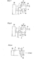
Fig. 4 is a plan view of a placement portion to place a position confirmation camera of the robot system according to the first embodiment; -
Fig. 5 is a flowchart for illustrating operations of the robot system according to the first embodiment; -
Fig. 6 is a diagram showing a state of moving the position confirmation camera of the robot system according to the first embodiment to the placement portion; -
Fig. 7 is a side elevational view showing a state of inserting the position confirmation camera of the robot system according to the first embodiment into the placement portion; -
Fig. 8 is a side elevational view showing a state of placing the position confirmation camera of the robot system according to the first embodiment on the placement portion; -
Fig. 9 is a top plan view showing a state of placing the position confirmation camera of the robot system according to the first embodiment on the placement portion; -
Fig. 10 is a diagram showing a state of grasping a work by a hand portion of the robot system according to the first embodiment; -
Fig. 11 is a diagram showing a state of examining (taking an image of) the work by an examination camera of the robot system according to the first embodiment; -
Fig. 12 is a diagram showing a state of examining (taking an image of) the work by rotating the hand portion by 90° in a direction E1 about an E-axis from the state shown inFig. 11 ; -
Fig. 13 is a diagram showing a state of examining (taking an image of) the work by rotating the hand portion by 90° in a direction F1 about an F-axis from the state shown inFig. 11 ; -
Fig. 14 is a diagram showing a state of examining (taking an image of) the work by rotating the hand portion by 90° in a direction F2 about the F-axis from the state shown inFig. 11 ; -
Fig. 15 is a diagram showing a state of inserting the work into a processing machine by the hand portion of the robot system according to the first embodiment; -
Fig. 16 is an overall view of a robot system according to a second embodiment; -
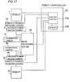
Fig. 17 is a block diagram of the robot system according to the second embodiment; -
Fig. 18 is a diagram showing an assembly operation of the robot system according to the second embodiment; and -
Fig. 19 is a diagram showing a state of examining (taking an image of) a work by a position confirmation camera of a robot system according to a modification of each of the first and second embodiments. - Embodiments are now described with reference to the drawings.
- First, the structure of a
robot system 100 according to a first embodiment is described with reference toFigs. 1 and2 . - As shown in
Fig. 1 , therobot system 100 includes arobot 1, arobot controller 2 controlling the overall operation of therobot system 100, animage processing system 3 to process an image, aposition confirmation camera 4 to confirm the positions of works (objects) 200, aplacement portion 5 to place theposition confirmation camera 4, and anexamination camera 6 to examine theworks 200. Aworkbench 201 is arranged adjacent to therobot system 100, and a plurality of the works 200 (fourworks 200 in the first embodiment) are placed on theworkbench 201. Aprocessing machine 300 to process theworks 200 is arranged adjacent to therobot system 100. Theposition confirmation camera 4 is an example of the "second imaging portion". Theexamination camera 6 is an example of the "first imaging portion.". Theworks 200 are examples of the "object to be grasped". - As shown in
Fig. 2 , therobot 1 is constituted by abase 11, alower arm 12, anupper arm 13, and awrist joint 14. Thebase 11 is provided with a rotatingportion 11a, and the rotatingportion 11a is formed to be rotatable about an A-axis. Thebase 11 and thelower arm 12 are connected to each other by afirst joint 15. Thefirst joint 15 is formed to rotate thelower arm 12 about a B-axis. Thelower arm 12 and theupper arm 13 are connected to each other by asecond joint 16. Theupper arm 13 includes a firstupper arm portion 13a connected to thesecond joint 16 and a secondupper arm portion 13b connected to thewrist joint 14. Thesecond joint 16 is formed to rotate theupper arm 13 about a C-axis. The secondupper arm portion 13b is formed to rotate about a D-axis. Thewrist joint 14 is formed to rotate about an E-axis and an F-axis. In other words, according to the first embodiment, therobot 1 is constituted by a six-axis vertical articulated robot rotatable about the A-axis to the F-axis. Ahand portion 17 to grasp theworks 200 is mounted on an end of thewrist joint 14. A camera mounting 18 to mount theposition confirmation camera 4 is provided on thewrist joint 14. Thelower arm 12, theupper arm 13, and thewrist joint 14 are examples of the "robot arm". Thehand portion 17 is an example of the "grasping portion". - The
position confirmation camera 4 is detachably mounted on the camera mounting 18 through a camera attaching/detachingportion 19. The camera attaching/detachingportion 19 includes an automatic tool changer (ATC), for example. This camera attaching/detachingportion 19 is constituted by abody portion 19a and an attaching/detachingportion 19b. The attaching/detachingportion 19b is attached to theposition confirmation camera 4, and fixed to thebody portion 19a by the pressure of air. Thus, theposition confirmation camera 4 is mounted to the wrist joint 14 (camera mounting 18). Theposition confirmation camera 4 includes a camera body, a lens, and a light. Theposition confirmation camera 4 is provided to take an image of the plurality ofworks 200 and confirm the positions of theworks 200. Theposition confirmation camera 4 and theimage processing system 3 are connected to each other by a wire 7 (seeFig. 1 ), and theexanimation camera 6 and theimage processing system 3 are connected to each other by a wire 8 (seeFig. 1 ). When theposition confirmation camera 4 is detached from the camera mounting 18, thewire 7 in addition to theposition confirmation camera 4 is detached from therobot 1. Thewires - As shown in
Fig. 3 , therobot controller 2 is provided with acontrol portion 21 and amemory 22. Thememory 22 is connected to thecontrol portion 21. Therobot 1 and theimage processing system 3 are connected to thecontrol portion 21 of therobot controller 2. The camera attaching/detachingportion 19 to attach/detach theposition confirmation camera 4 is connected to thecontrol portion 21 of therobot controller 2. Theposition confirmation camera 4 and theexamination camera 6 are connected to theimage processing system 3. According to the first embodiment, thecontrol portion 21 is so formed as to control the camera attaching/detachingportion 19 to detach theposition confirmation camera 4 from the camera mounting 18 mounted on the wrist joint 14 after confirming the positions of the plurality of works 200 (all fourworks 200 in the first embodiment) on the basis of the image taken by theposition confirmation camera 4 and before moving awork 200 that is being grasped by thehand portion 17 into theprocessing machine 300. - As shown in
Fig. 1 , theplacement portion 5 to place theposition confirmation camera 4 detached from the camera mounting 18 is mounted on apillar portion 50. As shown inFig. 4 , theplacement portion 5 is provided in the form of a plate, and provided with ahole 51 into which theposition confirmation camera 4 is inserted. Thehole 51 is so provided as to be continuous with anotch 52 provided on one end of theplacement portion 5 in the form of a plate. Theplacement portion 5 is also provided withbosses 53 to position theposition confirmation camera 4 when theposition confirmation camera 4 detached from the camera mounting 18 is placed. A plurality of the bosses 53 (twobosses 53 in the first embodiment) are so provided as to hold theposition confirmation camera 4 therebetween in plan view (top view) in a state where theposition confirmation camera 4 is placed on the placement portion 5 (seeFig. 9 ). - According to the first embodiment, the
examination camera 6 is fixedly mounted on aplacement portion 61 mount-ed on apillar portion 60, and provided separately from therobot 1, as shown inFig. 1 . A ring-shapedlighting portion 62 is arranged near theexamination camera 6. A plurality of LEDs (not shown) are attached to the ring-shapedlighting portion 62. Thelighting portion 62 is provided to emit light to thework 200 that is being grasped by thehand portion 17. According to the first embodiment, thecontrol portion 21 controls the camera attaching/detachingportion 19 to detach theposition confirmation camera 4 after taking an image of theworks 200 and confirming the positions of theworks 200 by theposition confirmation camera 4, controls therobot 1 to grasp one of theworks 200 by thehand portion 17, and controls theexamination camera 6 to examine thework 200 while driving therotating portion 11a of thebase 11, thelower arm 12, theupper arm 13, and the wrist joint 14 about multiple axes (A-axis to F-axis inFig. 2 ) to change the posture of thework 200 multiple times. Thecontrol portion 21 examines whether or not thework 200 is a conforming article (whether or not thework 200 is scratched or deformed) on the basis of images of thework 200 taken by theexamination camera 6. - The
examination camera 6 is arranged near a path to move thework 200 that is being grasped by thehand portion 17 into theprocessing machine 300. This path is previously taught to therobot controller 2. Therobot system 100 is so formed as to examine thework 200 that is being grasped by thehand portion 17 by theexamination camera 6 before thework 200 is moved into theprocessing machine 300. - The processing machine 300 (see
Fig. 1 ) has a function of processing (cutting, machining, lathing, grinding, NC machining, or the like) the works. When theworks 200 are processed in theprocessing machine 300, dust generated when theworks 200 are processed, coolant to cool theprocessing machine 300, oil, etc. are generated in theprocessing machine 300. - Next, operations of the
control portion 21 of therobot system 100 are described with reference toFigs. 1 and5 to 15 . - First, the
position confirmation camera 4 is mounted on the camera mounting 18 of therobot 1, and therobot 1 is so driven that theposition confirmation camera 4 is arranged above theworks 200 on theworkbench 201, as shown inFig. 1 . Then, an image of theworks 200 is taken by theposition confirmation camera 4 in the state where theposition confirmation camera 4 is arranged above theworks 200, as shown at a step S1 inFig. 5 . According to the first embodiment, an image of all the works 200 (four works 200) is taken. The image taken by theposition confirmation camera 4 is processed by theimage processing system 3, and processed data is transmitted to therobot controller 2 to be stored in thememory 22. Therobot controller 2 calculates (confirms) positions where theworks 200 are arranged on the basis of the data stored in thememory 22. Then, thecontrol portion 21 advances to a step S2. - As shown in
Fig. 5 , the robot 1 (therotating portion 11a of thebase 11, the first joint 15, the second joint 16, and the wrist joint 14) is so driven that theposition confirmation camera 4 is moved near theplacement portion 5 as shown inFig. 6 at the step S2. Then, theposition confirmation camera 4 is inserted into thehole 51 of theplacement portion 5 along thebosses 53, as shown inFig. 7 , and theposition confirmation camera 4 is placed on theplacement portion 5, as shown inFig. 8 . In a state where theposition confirmation camera 4 is placed on theplacement portion 5, the outer surface of the camera attaching/detaching portion 19 (attaching/detachingportion 19b) comes into contact with the twobosses 53 as shown inFig. 9 so that the camera attaching/detaching portion 19 (position confirmation camera 4) is positioned. Thereafter, the camera attaching/detachingportion 19 operates to detach theposition confirmation camera 4 from the camera mounting 18 (wrist joint 14). At this time, thewire 7 in addition to theposition confirmation camera 4 is also detached from the camera mounting 18. Then, thecontrol portion 21 advances to a step S3. - As shown in
Fig. 5 , therobot 1 is so driven on the basis of the positions where theworks 200 are arranged calculated (confirmed) by therobot controller 2 that one of theworks 200 is grasped by thehand portion 17 as shown inFig. 10 at the step S3. Then, thecontrol portion 21 advances to a step S4. - As shown in
Fig. 5 , therobot 1 is so driven that thework 200 that is being grasped by thehand portion 17 is arranged in front of theexamination camera 6 as shown inFig. 11 , and images of thework 200 are taken by theexamination camera 6 at the step S4. At this time, the ring-shapedlighting portion 62 emits light to thework 200 that is being grasped by thehand portion 17. Thus, an image of an A-surface of thework 200 is taken. - As shown in
Fig. 12 , the wrist joint 14 is rotated by 90° in a direction E1 about the E-axis from the state shown inFig. 11 to change the posture of thework 200, and an image of thework 200 is taken by theexamination camera 6. Thus, an image of a B-surface of thework 200 is taken. Therobot system 100 may be so formed as to take an image of thework 200 once after thework 200 is postured as shown inFig. 12 , or may be so formed as to take images of thework 200 continuously during rotation of the wrist joint 14. - As shown in
Fig. 13 , the wrist joint 14 is rotated by 90° in a direction F1 about the F-axis from the state shown inFig. 11 to change the posture of thework 200, and an image of thework 200 is taken by theexamination camera 6. Thus, an image of a C-surface of thework 200 is taken. - As shown in
Fig. 14 , the wrist joint 14 is rotated by 90° in a direction F2 about the F-axis from the state shown inFig. 11 to change the posture of thework 200, and an image of thework 200 is taken by theexamination camera 6. Thus, an image of a D-surface of thework 200 is taken. The images taken by theexamination camera 6 are processed by theimage processing system 3, and processed data is transmitted to therobot controller 2 to be stored in thememory 22. Therobot controller 2 examines whether or not the surface of thework 200 is scratched, whether or not thework 200 is deformed, etc., for example, on the basis of the data stored in thememory 22. Then, thecontrol portion 21 advances to a step S5. - As shown in
Fig. 5 , therobot 1 is so driven that thework 200 is inserted into the processing machine 300 (thework 200 is put to the processing machine 300) as shown inFig. 15 at the step S5, and thework 200 is processed. Thereafter, the steps S3 to S5 are so repeated that all theworks 200 are processed. - According to the first embodiment, as hereinabove described, the
control portion 21 controls theexamination camera 6 fixedly set separately from therobot 1 to examine thework 200 while driving the robot 1 (therotating portion 11a of thebase 11, thelower arm 12, theupper arm 13, and the wrist joint 14) to change the posture of thework 200 multiple times. Thus, the posture of thework 200 is changed multiple times by therobot 1 relatively with respect to theexamination camera 6 fixedly set separately from therobot 1, and hence thework 200 can be examined from multiple angles of view by theexamination camera 6. - According to the first embodiment, as hereinabove described, the
robot 1 is constituted by a vertical articulated robot capable of being driven about multiple axes (A-axis to F-axis), thework 200 is grasped by thehand portion 17, and thecontrol portion 21 controls theexamination camera 6 to examine thework 200 while driving therobot 1 about the multiple axes to change the posture of thework 200 multiple times. Thus, the posture of thework 200 can be easily changed multiple times, and hence thework 200 can be easily examined from multiple angles of view. - According to the first embodiment, as hereinabove described, the
control portion 21 examines whether or not theworks 200 are conforming articles on the basis of the images of theworks 200 taken by theexamination camera 6. Thus, a scratch or the like on the surfaces of theworks 200 is detected, whereby adefective work 200 can be suppressed from being processed by theprocessing machine 300. - According to the first embodiment, as hereinabove described, the
control portion 21 controls the camera attaching/detachingportion 19 to detach theposition confirmation camera 4 after taking an image of theworks 200 and confirming the positions of theworks 200 by theposition confirmation camera 4. Thus, theposition confirmation camera 4 has been already detached when thework 200 that is being grasped by thehand portion 17 is moved into the processing machine 300 (adverse environment), and hence degradation in the performance of theposition confirmation camera 4 due to oil, dust, etc. in the adverse environment can be suppressed. - According to the first embodiment, as hereinabove described, the
robot system 100 is provided with thelighting portion 62 to emit light to thework 200, arranged near theexamination camera 6 set separately from therobot 1. Thus, the posture of thework 200 is changed multiple times, whereby the light from thelighting portion 62 is emitted to thework 200 from multiple angles, and hence a scratch or the like on the surface of thework 200 can be reliably detected. - According to the first embodiment, as hereinabove described, the
examination camera 6 is arranged near the path to move thework 200 that is being grasped by thehand portion 17 into theprocessing machine 300. Thus, the time (takt time) required for steps from grasping thework 200 through examining thework 200 to moving thework 200 into theprocessing machine 300 can be reduced, dissimilarly to a case where theexamination camera 6 is distanced from the path to move thework 200 into theprocessing machine 300. - According to the first embodiment, as hereinabove described, the
work 200 is examined by theexamination camera 6 before thework 200 that is being grasped by thehand portion 17 is moved into theprocessing machine 300. Thus, adefective work 200 can be suppressed from being moved into theprocessing machine 300. - A second embodiment is now described with reference to
Figs. 16 and17 . In this second embodiment, arobot system 101 is provided with tworobots robot system 100 is provided with thesingle robot 1. - As shown in
Fig. 16 , therobot system 101 according to the second embodiment includes therobot 1, arobot controller 2a controlling the overall operation of therobot system 101, an image processing unit (image processor) 3a to process an image, aposition confirmation camera 4 to confirm the positions ofworks 210 each made of a shaft, for example, aplacement portion 5 to place theposition confirmation camera 4, and anexamination camera 6 to examine theworks 210, similarly to the aforementioned first embodiment. Therobot 1 and theplacement portion 5 are similar in structure to those in the aforementioned first embodiment. Theworks 210 each made of a shaft, for example, grasped by ahand portion 17 of therobot 1 are arranged on aworkbench 201. Therobot 1 is an example of the "first robot". Theworks 210 are examples of the "first object to be grasped". - The
examination camera 6 is arranged near a path to move awork 210 that is being grasped by thehand portion 17 to a position where thework 210 is combined with awork 220 that is being grasped by ahand portion 75 of therobot 70. Thework 210 that is being grasped by thehand portion 17 is examined by theexamination camera 6 before thework 210 is moved to the position where thework 210 is combined with thework 220 that is being grasped by thehand portion 75 of therobot 70. - The
robot system 101 further includes therobot 70, aposition confirmation camera 4a to confirm the positions ofworks 220 each made of a shaft bearing, for example, aplacement portion 5a to place theposition confirmation camera 4a, and anexamination camera 6a to examine theworks 220. Therobot 70 is constituted by abase 71, alower arm 72, anupper arm 73, and a wrist joint 74, similarly to therobot 1. Thehand portion 75 is mounted on the wrist joint 74. A camera attaching/detachingportion 76 of therobot 70 is connected to theimage processing unit 3a through awire 7a. Theexamination camera 6a is connected to theimage processing unit 3a through awire 8a. The structure of theplacement portion 5a according to the second embodiment is similar to that of theplacement portion 5 according to the first embodiment (seeFig. 4 ). Theworks 220 each made of a shaft bearing, for example, grasped by thehand portion 75 are arranged on aworkbench 221. Therobot 70 is an example of the "second robot". Theexamination camera 6a is an example of the "first imaging portion". Theposition confirmation camera 4a is an example of the "second imaging portion". Thelower arm 72, theupper arm 73, and the wrist joint 74 are examples of the "robot arm". Thehand portion 75 is an example of the "grasping portion". Theworks 220 are examples of the "second object to be grasped". - The
examination camera 6a is arranged near a path to move thework 220 that is being grasped by thehand portion 75 to a position where thework 220 is combined with thework 210 that is being grasped by thehand portion 17 of therobot 1. Thework 220 that is being grasped by thehand portion 75 is examined by theexamination camera 6a before thework 220 is moved to the position where thework 220 is combined with thework 210 that is being grasped by thehand portion 17 of therobot 1. - As shown in
Fig. 17 , therobot controller 2a is provided with acontrol portion 21a and amemory 22a. Thememory 22a is connected to thecontrol portion 21a. Therobots image processing unit 3a are connected to thecontrol portion 21a of therobot controller 2a. Camera attaching/detachingportions position confirmation cameras control portion 21a of therobot controller 2a. Theposition confirmation cameras examination cameras image processing unit 3a. According to the second embodiment, thecontrol portion 21a is so formed as to examine a state of the work 210 (work 220) that is being grasped by the hand portion 17 (hand portion 75) on the basis of images taken by the examination camera 6 (examination camera 6a). Specifically, thecontrol portion 21a examines a position where the work 210 (work 220) is being grasped by the hand portion 17 (hand portion 75), the posture of the work 210 (work 220), etc. Then, thecontrol portion 21a combines thework 210 that is being grasped by thehand portion 17 of therobot 1 and thework 220 that is being grasped by thehand portion 75 of therobot 70 on the basis of the state of thework 210 that is being grasped by thehand portion 17 of therobot 1, having been examined by theexamination camera 6 and the state of thework 220 that is being grasped by thehand portion 75 of therobot 70, having been examined by theexamination camera 6a. - Operations of the
control portion 21a of therobot system 101 are now described with reference toFigs. 16 and18 . - First, the
position confirmation camera 4 is mounted to therobot 1, and therobot 1 is so driven that theposition confirmation camera 4 is arranged above theworks 210 on theworkbench 201, as shown inFig. 16 . Thereafter, the steps S1 to S4 inFig. 5 are sequentially performed. In other words, an image of theworks 210 is taken by theposition confirmation camera 4, and the positions of theworks 210 are confirmed on the basis of the image taken by theposition confirmation camera 4. Then, theposition confirmation camera 4 is detached to be placed on theplacement portion 5, and thereafter one of theworks 210 is grasped by thehand portion 17 of therobot 1. Then, images of thework 210 that is being grasped by thehand portion 17 of therobot 1 are taken by the examination camera 6 (seeFigs. 11 to 14 ) while the posture of thework 210 is changed multiple times. The state of thework 210 that is being grasped by the hand portion 17 (the position where thework 210 is being grasped, the posture of thework 210, etc.) is examined on the basis of the images of thework 210 taken by theexamination camera 6. - Next, the
robot 70 is so driven that theposition confirmation camera 4a mounted to therobot 70 is arranged above theworks 220 on theworkbench 221. Thereafter, the steps S1 to S4 inFig. 5 are sequentially performed, similarly to the case of theaforementioned robot 1. In other words, an image of theworks 220 is taken by theposition confirmation camera 4a, the positions of theworks 220 are confirmed, theposition confirmation camera 4a is detached, one of theworks 220 is grasped by thehand portion 75, images of thework 220 are taken by theexamination camera 6a, and the state of thework 220 that is being grasped by thehand portion 75 is examined. - Then, the
work 210 that is being grasped by thehand portion 17 of therobot 1 and thework 220 that is being grasped by thehand portion 75 of therobot 70 are combined on the basis of the state of thework 210 that is being grasped by thehand portion 17 of therobot 1, having been examined by theexamination camera 6 and the state of thework 220 that is being grasped by thehand portion 75 of therobot 70, having been examined by theexamination camera 6a, as shown inFig. 18 . Specifically, the work 210 (shaft) that is being grasped by thehand portion 17 of therobot 1 is inserted into the work 220 (shaft bearing) that is being grasped by thehand portion 75 of therobot 70. - According to the second embodiment, as hereinabove described, the
control portion 21a examines the state of thework 210 that is being grasped by thehand portion 17 on the basis of the images of thework 210 taken by theexamination camera 6, and examines the state of thework 220 that is being grasped by thehand portion 75 on the basis of the images of thework 220 taken by theexamination camera 6a. Thus, the state of thework 210 that is being grasped by thehand portion 17 of therobot 1 and the state of thework 220 that is being grasped by thehand portion 75 of therobot 70 are confirmed, and hence operations of therobot 1 and therobot 70 can be controlled on the basis of the states of thework 210 that is being grasped by thehand portion 17 and thework 220 that is being grasped by thehand portion 75. - According to the second embodiment, as hereinabove described, the
control portion 21a controls therobot 1 and therobot 70 to combine thework 210 and thework 220 on the basis of the state of thework 210 that is being grasped by thehand portion 17 of the robot 1 (the position where thework 210 is being grasped, the posture of thework 210, etc.), having examined by theexamination camera 6 and the state of thework 220 that is being grasped by thehand portion 75 of the robot 70 (the position where thework 220 is being grasped, the posture of thework 220, etc.), having examined by theexamination camera 6a. Thus, thework 210 and thework 220 can be reliably combined. - Although the disclosure has been described and illustrated in detail, it is clearly understood that the same is by way of illustration and example only and is not to be taken by way of limitation, the spirit and scope of the present invention being limited only by the terms of the appended claims.
- For example, while the wrist joint is rotated about the E-axis (see
Fig. 12 ) and the F-axis (seeFigs. 13 and14 ) to change the posture of the work multiple times in each of the aforementioned first and second embodiments, the present invention is not restricted to this. The robot may alternatively be rotated about axes other than the E-axis and the F-axis to change the posture of the work multiple times. - While the position confirmation camera is detached and the works are examined, after the image of all the works is taken and the positions of all the works are confirmed by the position confirmation camera in each of the aforementioned first and second embodiments, the present invention is not restricted to this. Alternatively, the position confirmation camera may be detached and the works (or the work) may be examined, after an image of some (or an image of one) of all the works is taken and the positions of some (or the position of one) of all the works are confirmed, for example.
- While the works are examined after the position confirmation camera is detached in each of the aforementioned first and second embodiments, the present invention is not restricted to this. The position confirmation camera may alternatively be detached after the works are examined, for example.
- While the position confirmation camera and the examination camera are separately provided in each of the aforementioned first and second embodiments, the present invention is not restricted to this. For example, the robot system may alternatively be so formed as to take an image of the works and confirm the positions of the works by the position confirmation camera, detach the position confirmation camera from the arm of the robot and fixedly place the same on the placement portion, and thereafter take images of the work and examine the work by the position confirmation camera having been placed on the placement portion, as in a modification shown in
Fig. 19 . Thus, the position confirmation camera can also serve as the examination camera, and hence the structure of the robot system can be simplified. - While the robot system is so formed as to examine whether or not the works are conforming articles in the aforementioned first embodiment, and the robot system is so formed as to examine the states of the works that are being grasped by the robots in the aforementioned second embodiment, the present invention is not restricted to this. The robot system may alternatively be so formed as to examine both whether or not the works are conforming articles and the state(s) of the works that are being grasped by the robot(s), for example.
- While the robot system is so formed as to examine both the state of the
work 210 that is being grasped by therobot 1 and the state of thework 220 that is being grasped by therobot 70 in the aforementioned second embodiment, the present invention is not restricted to this. The robot system may alternatively be so formed as to examine either the state of thework 210 that is being grasped by therobot 1 or the state of thework 220 that is being grasped by therobot 70. - While the
robot system 101 has the tworobots
Claims (15)
- A robot system (100, 101) comprising:a robot (1, 70) including a robot arm (12, 13, 14, 72, 73, 74) mounted with a grasping portion (17, 75) to grasp an object to be grasped (200, 210, 220);a first imaging portion (6, 6a) to examine said object to be grasped that is being grasped by said grasping portion, disposed separately from said robot arm; anda control portion (21, 21a) configured to operate the robot and the first imaging portion, whereinsaid control portion is configured to operate said robot to grasp said object to be grasped by said grasping portion, and operate said first imaging portion to examine said object multiple times while operating said robot arm to change a posture of said object.
- The robot system according to claim 1, wherein
said robot includes a vertical articulated robot capable of being driven about multiple axes, and
said control portion is configured to operate said robot to grasp said object by said grasping portion, and operate said first imaging portion to examine said object multiple times while driving said robot arm about said multiple axes to change the posture of said object. - The robot system according to claim 1 or 2, whereinsaid control portion is configured to operate said first imaging portion to take an image of said object and examine said object each time when said robot arm is operated to change the posture of said object multiple times.
- The robot system according to any one of claims 1 to 3, whereinsaid control portion is configured to examine whether or not said object to be grasped is a conforming article on the basis of an image of said object to be grasped taken by said first imaging portion.
- The robot system according to any one of claims 1 to 4, whereinsaid control portion is configured to examine a state of said object to be grasped that is being grasped by said grasping portion on the basis of an image of said object to be grasped taken by said first imaging portion.
- The robot system according to claim 5, whereinsaid control portion is configured to examine at least either a position of said object to be grasped that is being grasped by said grasping portion or a posture of said object to be grasped that is being grasped by said grasping portion on the basis of the image of said object to be grasped taken by said first imaging portion.
- The robot system according to any one of claims 1 to 6, further comprising a second imaging portion (4, 4a) mounted to said robot arm, whereinsaid control portion is configured to detach said second imaging portion after taking an image of said object to be grasped and confirming a position of said object to be grasped by said second imaging portion, control said robot to grasp said object to be grasped by said grasping portion, and control said first imaging portion to examine said object to be grasped while driving said robot arm to change the posture of said object to be grasped multiple times.
- The robot system according to any one of claims 1 to 7, further comprising a lighting portion (62) to emit light to said object to be grasped, arranged near said first imaging portion set separately from said robot.
- The robot system according to any one of claims 1 to 8, whereinsaid first imaging portion is arranged near a path to move said object to be grasped that is being grasped by said grasping portion to a prescribed,processing position.
- The robot system according to any one of claims 1 to 9, further comprising an image processor (3, 3a) to process an image taken by said first imaging portion, whereinsaid control portion is configured to examine said object to be grasped on the basis of an image processed by said image processor.
- The robot system according to any one of claims 1 to 10, whereinsaid control portion is configured to control said robot to grasp said object to be grasped by said grasping portion, and control said first imaging portion to examine said object to be grasped while driving said robot arm to change the posture of said object to be grasped multiple times before moving said object to be grasped that is being grasped by said grasping portion into a processing machine (300).
- The robot system according to any one of claims 1 to 11, further comprising a second imaging portion (4, 4a) mounted to said robot arm, whereinsaid first imaging portion to examine said object to be grasped that is being grasped by said grasping portion and said second imaging portion mounted to said robot arm are constituted by a same imaging portion, andsaid control portion is configured to detach said imaging portion and disposed said imaging portion after taking an image of said object to be grasped and confirming a position of said object to be grasped by said imaging portion mounted to said robot arm, control said robot to grasp said object to be grasped by said grasping portion, and control said imaging portion to examine said object to be grasped while driving said robot arm to change the posture of said object to be grasped multiple times.
- The robot system according to claim 12, further comprising a placement portion (5) to place said imaging portion detached from said robot arm, whereinsaid control portion is configured to detach said imaging portion and fixedly place said imaging portion on said placement portion after taking the image of said object to be grasped and confirming the position of said object to be grasped by said imaging portion mounted to said robot arm, control said robot to grasp said object to be grasped by said grasping portion, and control said imaging portion having been placed on said placement portion to examine said object to be grasped while driving said robot arm to change the posture of said object to be grasped multiple times.
- The robot system according to any one of claims 1 to 13, whereinsaid robot includes a pair of a first robot (1) and a second robot (70) each having a robot arm,said object to be grasped includes a first object to be grasped (210) by a grasping portion of said first robot and a second object to be grasped (220) by a grasping portion of said second robot, andsaid control portion is configured to control said first imaging portion to examine a state of said first object to be grasped that is being grasped by said grasping portion of said first robot while driving said robot arm of said first robot to change a posture of said first object to be grasped multiple times after grasping said first object to be grasped by said grasping portion of said first robot, and combine said first object to be grasped that is being grasped by said grasping portion of said first robot and said second object to be grasped that is being grasped by said grasping portion of said second robot on the basis of the state of said first object to be grasped that is being grasped by said grasping portion of said first robot, having been examined by said first imaging portion.
- A processed object manufacturing method comprising:grasping an object to be grasped (200, 210, 220) by a grasping portion (17, 75) mounted to a robot arm;examining the object multiple times by an imaging portion (6, 6a) disposed separately from the robot arm while operating the robot arm to change a posture of the object that is being grasped by the grasping portion;putting the object to a processing machine (300); and processing the object by the processing machine.
Applications Claiming Priority (1)
| Application Number | Priority Date | Filing Date | Title |
|---|---|---|---|
| JP2011091398A JP5382053B2 (en) | 2011-04-15 | 2011-04-15 | Robot system and inspection method using robot system |
Publications (1)
| Publication Number | Publication Date |
|---|---|
| EP2511054A2 true EP2511054A2 (en) | 2012-10-17 |
Family
ID=45655930
Family Applications (1)
| Application Number | Title | Priority Date | Filing Date |
|---|---|---|---|
| EP12155737A Withdrawn EP2511054A2 (en) | 2011-04-15 | 2012-02-16 | Robot system and processed object manufacturing method |
Country Status (4)
| Country | Link |
|---|---|
| US (1) | US9031696B2 (en) |
| EP (1) | EP2511054A2 (en) |
| JP (1) | JP5382053B2 (en) |
| CN (1) | CN102729253A (en) |
Cited By (5)
| Publication number | Priority date | Publication date | Assignee | Title |
|---|---|---|---|---|
| US10406644B2 (en) | 2016-04-28 | 2019-09-10 | Fanuc Corporation | Machining system |
| US11565421B2 (en) | 2017-11-28 | 2023-01-31 | Fanuc Corporation | Robot and robot system |
| EP4235539A3 (en) * | 2015-09-11 | 2023-09-27 | Berkshire Grey Operating Company, Inc. | Robotic systems and methods for identifying and processing a variety of objects |
| US11986859B2 (en) | 2015-12-18 | 2024-05-21 | Berkshire Grey Operating Company, Inc. | Perception systems and methods for identifying and processing a variety of objects |
| US12350713B2 (en) | 2015-12-18 | 2025-07-08 | Berkshire Grey Operating Company, Inc. | Perception systems and methods for identifying and processing a variety of objects |
Families Citing this family (20)
| Publication number | Priority date | Publication date | Assignee | Title |
|---|---|---|---|---|
| JP5480246B2 (en) * | 2009-03-11 | 2014-04-23 | 本田技研工業株式会社 | Working apparatus and working method |
| JP5382053B2 (en) * | 2011-04-15 | 2014-01-08 | 株式会社安川電機 | Robot system and inspection method using robot system |
| JP5664629B2 (en) * | 2012-10-19 | 2015-02-04 | 株式会社安川電機 | Robot system and method of manufacturing processed product |
| CN104084953A (en) * | 2014-07-28 | 2014-10-08 | 朱德金 | Multifunctional mechanical arm |
| CN104924302A (en) * | 2015-06-04 | 2015-09-23 | 广西大学 | Six-degree-of-freedom handling mechanical arm |
| CN105128009A (en) * | 2015-08-10 | 2015-12-09 | 深圳百思拓威机器人技术有限公司 | Bionic robot with object shape and pose accurate sensing function and sensing method of bionic robot |
| CN107745380A (en) * | 2017-10-23 | 2018-03-02 | 深圳智英电子有限公司 | A kind of top box of digital machine Automation of Manufacturing Process test handler |
| JP6923688B2 (en) * | 2017-11-28 | 2021-08-25 | ファナック株式会社 | Robots and robot systems |
| JP6773713B2 (en) * | 2018-03-29 | 2020-10-21 | ファナック株式会社 | Robot system |
| US20210187728A1 (en) * | 2018-06-19 | 2021-06-24 | Bae Systems Plc | Workbench system |
| WO2019243798A1 (en) * | 2018-06-19 | 2019-12-26 | Bae Systems Plc | Workbench system |
| ES2919649T3 (en) | 2018-06-19 | 2022-07-27 | Bae Systems Plc | workbench system |
| EP3584653A1 (en) * | 2018-06-19 | 2019-12-25 | BAE SYSTEMS plc | Workbench system |
| CN111002287B (en) * | 2019-12-26 | 2021-11-30 | 北京海益同展信息科技有限公司 | Robot, image acquisition method, electronic device, and computer-readable storage medium |
| JP7531196B2 (en) * | 2020-09-09 | 2024-08-09 | オムロン株式会社 | Robot system and picking method |
| US12204314B2 (en) | 2020-11-10 | 2025-01-21 | Bright Machines, Inc. | Method and apparatus for improved auto-calibration of a robotic cell |
| KR102470581B1 (en) * | 2021-02-17 | 2022-11-25 | (주)소프트피브이 | Pick-up apparatus transferring object having at least partially curved surface and method pickking-up for the same |
| WO2023288233A1 (en) | 2021-07-16 | 2023-01-19 | Bright Machines, Inc. | Method and apparatus for vision-based tool localization |
| CN113681563B (en) * | 2021-08-31 | 2022-10-18 | 上海交大智邦科技有限公司 | Assembling method and system based on double cameras |
| JP2024171841A (en) * | 2023-05-30 | 2024-12-12 | 川崎重工業株式会社 | robot |
Citations (1)
| Publication number | Priority date | Publication date | Assignee | Title |
|---|---|---|---|---|
| JP2011000669A (en) | 2009-06-18 | 2011-01-06 | Yaskawa Electric Corp | Robot system and article aligning method |
Family Cites Families (22)
| Publication number | Priority date | Publication date | Assignee | Title |
|---|---|---|---|---|
| JPS60146697A (en) * | 1984-01-06 | 1985-08-02 | キヤノン株式会社 | work robot |
| JPS6257884A (en) * | 1985-09-09 | 1987-03-13 | 株式会社東芝 | Manipulator device |
| JPH0626770B2 (en) * | 1989-11-17 | 1994-04-13 | 川崎重工業株式会社 | Workpiece fitting method |
| JPH06160066A (en) * | 1992-11-24 | 1994-06-07 | Sekisui Chem Co Ltd | Apparatus for visual inspection |
| JPH08304510A (en) * | 1995-05-10 | 1996-11-22 | Hitachi Ltd | IC attachment / detachment device |
| US5804585A (en) * | 1996-04-15 | 1998-09-08 | Texas Biotechnology Corporation | Thieno-pyridine sulfonamides derivatives thereof and related compounds that modulate the activity of endothelin |
| US6804585B2 (en) * | 2001-06-19 | 2004-10-12 | John Jay Humbard | Flight management system and method for providing navigational reference to emergency landing locations |
| JP2004142015A (en) * | 2002-10-24 | 2004-05-20 | Fanuc Ltd | Robot with sensor |
| JP3865703B2 (en) * | 2002-10-25 | 2007-01-10 | ファナック株式会社 | Article conveying system and conveying method |
| JP3876234B2 (en) * | 2003-06-17 | 2007-01-31 | ファナック株式会社 | Connector gripping device, connector inspection system and connector connection system equipped with the same |
| JP4021413B2 (en) * | 2004-01-16 | 2007-12-12 | ファナック株式会社 | Measuring device |
| US8027758B2 (en) * | 2005-01-19 | 2011-09-27 | Airbus Operations (S.A.S.) | Navigation system for an aircraft and associated command process |
| US7874521B2 (en) * | 2005-10-17 | 2011-01-25 | Hoshiko Llc | Method and system for aviation navigation |
| JP4020144B2 (en) | 2006-03-10 | 2007-12-12 | オムロン株式会社 | Inspection method of surface condition |
| US8032267B1 (en) * | 2006-04-03 | 2011-10-04 | Honeywell International Inc. | Aviation navigational and flight management systems and methods with emergency landing guidance and radar vectoring |
| DE102007060653A1 (en) * | 2007-12-15 | 2009-06-18 | Abb Ag | Position determination of an object |
| JP2009148845A (en) * | 2007-12-19 | 2009-07-09 | Olympus Corp | Small-size production equipment |
| US8035547B1 (en) * | 2008-03-17 | 2011-10-11 | Garmin Switzerland Gmbh | System and method of assisted aerial navigation |
| US8457889B2 (en) * | 2008-03-31 | 2013-06-04 | Honeywell International Inc. | Waypoint display system and method |
| US8140260B2 (en) * | 2010-02-12 | 2012-03-20 | Honeywell International Inc. | System for enhancing a vehicle operator's orientation and ability to navigate |
| JP5382053B2 (en) * | 2011-04-15 | 2014-01-08 | 株式会社安川電機 | Robot system and inspection method using robot system |
| JP5664629B2 (en) * | 2012-10-19 | 2015-02-04 | 株式会社安川電機 | Robot system and method of manufacturing processed product |
-
2011
- 2011-04-15 JP JP2011091398A patent/JP5382053B2/en active Active
-
2012
- 2012-02-16 EP EP12155737A patent/EP2511054A2/en not_active Withdrawn
- 2012-02-16 US US13/397,682 patent/US9031696B2/en active Active
- 2012-02-28 CN CN2012100484570A patent/CN102729253A/en active Pending
Patent Citations (1)
| Publication number | Priority date | Publication date | Assignee | Title |
|---|---|---|---|---|
| JP2011000669A (en) | 2009-06-18 | 2011-01-06 | Yaskawa Electric Corp | Robot system and article aligning method |
Cited By (8)
| Publication number | Priority date | Publication date | Assignee | Title |
|---|---|---|---|---|
| EP4235539A3 (en) * | 2015-09-11 | 2023-09-27 | Berkshire Grey Operating Company, Inc. | Robotic systems and methods for identifying and processing a variety of objects |
| EP4235540A3 (en) * | 2015-09-11 | 2023-09-27 | Berkshire Grey Operating Company, Inc. | Robotic systems and methods for identifying and processing a variety of objects |
| US12159192B2 (en) | 2015-09-11 | 2024-12-03 | Berkshire Grey Operating Company, Inc. | Robotic systems and methods for identifying and processing a variety of objects |
| US11986859B2 (en) | 2015-12-18 | 2024-05-21 | Berkshire Grey Operating Company, Inc. | Perception systems and methods for identifying and processing a variety of objects |
| US12350713B2 (en) | 2015-12-18 | 2025-07-08 | Berkshire Grey Operating Company, Inc. | Perception systems and methods for identifying and processing a variety of objects |
| US10406644B2 (en) | 2016-04-28 | 2019-09-10 | Fanuc Corporation | Machining system |
| US11565421B2 (en) | 2017-11-28 | 2023-01-31 | Fanuc Corporation | Robot and robot system |
| US11992962B2 (en) | 2017-11-28 | 2024-05-28 | Fanuc Corporation | Robot and robot system |
Also Published As
| Publication number | Publication date |
|---|---|
| JP2012223840A (en) | 2012-11-15 |
| US9031696B2 (en) | 2015-05-12 |
| JP5382053B2 (en) | 2014-01-08 |
| US20120265345A1 (en) | 2012-10-18 |
| CN102729253A (en) | 2012-10-17 |
Similar Documents
| Publication | Publication Date | Title |
|---|---|---|
| US9031696B2 (en) | Robot system and processed object manufacturing method | |
| EP2511055B1 (en) | Robot system and method for operating robot system | |
| TWI722180B (en) | Machine tool | |
| FI123306B (en) | Robot tool system and procedure for its control, computer software and software product | |
| US10293499B2 (en) | Movable robot | |
| JP5910724B2 (en) | Robot system | |
| JP7188880B2 (en) | Machine Tools | |
| US11992962B2 (en) | Robot and robot system | |
| WO2021039829A1 (en) | Production system | |
| JP7288367B2 (en) | machine tool system | |
| TW201808520A (en) | Machine tool | |
| CN108349092A (en) | Manufacturing system, manufacturing system construction method, end effector, robot, and robot operation method | |
| CN109952178B (en) | Working robot and working position correction method | |
| JP2022126768A (en) | Robot-equipped moving device | |
| US10328582B2 (en) | Process system including robot that transfers workpiece to process machine | |
| EP3175958B1 (en) | 5-axis and 6-axis mixing control method for industrial robot and system thereof | |
| JP2019130646A (en) | Working robot system | |
| JP2020049549A (en) | Robot unit | |
| CN118321857B (en) | Automatic control system for disassembling waste display by utilizing automatic tool changing system | |
| JP2026008686A (en) | Transport system, transport system control method and program | |
| JP2021058980A (en) | Production system | |
| WO2023032400A1 (en) | Automatic transport device, and system | |
| CN117396311A (en) | Workstations and how to operate them | |
| JP7648838B1 (en) | Transport Systems and Robots | |
| JP2015085457A (en) | Robot, robot system, and robot control device |
Legal Events
| Date | Code | Title | Description |
|---|---|---|---|
| PUAI | Public reference made under article 153(3) epc to a published international application that has entered the european phase |
Free format text: ORIGINAL CODE: 0009012 |
|
| AK | Designated contracting states |
Kind code of ref document: A2 Designated state(s): AL AT BE BG CH CY CZ DE DK EE ES FI FR GB GR HR HU IE IS IT LI LT LU LV MC MK MT NL NO PL PT RO RS SE SI SK SM TR |
|
| AX | Request for extension of the european patent |
Extension state: BA ME |
|
| STAA | Information on the status of an ep patent application or granted ep patent |
Free format text: STATUS: THE APPLICATION HAS BEEN WITHDRAWN |
|
| 18W | Application withdrawn |
Effective date: 20160707 |