EP2510993A1 - Fluid filter and method of filtering - Google Patents
Fluid filter and method of filtering Download PDFInfo
- Publication number
- EP2510993A1 EP2510993A1 EP12002610A EP12002610A EP2510993A1 EP 2510993 A1 EP2510993 A1 EP 2510993A1 EP 12002610 A EP12002610 A EP 12002610A EP 12002610 A EP12002610 A EP 12002610A EP 2510993 A1 EP2510993 A1 EP 2510993A1
- Authority
- EP
- European Patent Office
- Prior art keywords
- filter
- basket
- filtering
- strainer
- wastewater
- Prior art date
- Legal status (The legal status is an assumption and is not a legal conclusion. Google has not performed a legal analysis and makes no representation as to the accuracy of the status listed.)
- Withdrawn
Links
- 238000001914 filtration Methods 0.000 title claims abstract description 62
- 238000000034 method Methods 0.000 title claims description 11
- 239000012530 fluid Substances 0.000 title abstract description 10
- 239000002351 wastewater Substances 0.000 claims abstract description 36
- 239000000463 material Substances 0.000 claims abstract description 25
- 239000002861 polymer material Substances 0.000 claims description 14
- 239000002245 particle Substances 0.000 claims description 10
- 238000005086 pumping Methods 0.000 claims description 7
- XLYOFNOQVPJJNP-UHFFFAOYSA-N water Substances O XLYOFNOQVPJJNP-UHFFFAOYSA-N 0.000 claims description 6
- 230000000845 anti-microbial effect Effects 0.000 claims description 3
- 239000004599 antimicrobial Substances 0.000 claims description 3
- -1 polyethylene Polymers 0.000 abstract description 5
- 239000004698 Polyethylene Substances 0.000 abstract description 3
- 229920000573 polyethylene Polymers 0.000 abstract description 3
- 229920000642 polymer Polymers 0.000 abstract description 2
- 230000008878 coupling Effects 0.000 description 5
- 238000010168 coupling process Methods 0.000 description 5
- 238000005859 coupling reaction Methods 0.000 description 5
- 238000011065 in-situ storage Methods 0.000 description 5
- 238000007789 sealing Methods 0.000 description 5
- 239000011236 particulate material Substances 0.000 description 4
- 230000000717 retained effect Effects 0.000 description 3
- 239000010935 stainless steel Substances 0.000 description 3
- 230000004075 alteration Effects 0.000 description 2
- 239000003638 chemical reducing agent Substances 0.000 description 2
- 238000010586 diagram Methods 0.000 description 2
- 239000000706 filtrate Substances 0.000 description 2
- 238000012986 modification Methods 0.000 description 2
- 230000004048 modification Effects 0.000 description 2
- 150000001282 organosilanes Chemical class 0.000 description 2
- 229920000139 polyethylene terephthalate Polymers 0.000 description 2
- 239000005020 polyethylene terephthalate Substances 0.000 description 2
- 229910001220 stainless steel Inorganic materials 0.000 description 2
- 230000001629 suppression Effects 0.000 description 2
- 241000894006 Bacteria Species 0.000 description 1
- 230000033228 biological regulation Effects 0.000 description 1
- 230000007613 environmental effect Effects 0.000 description 1
- 239000008187 granular material Substances 0.000 description 1
- 230000005484 gravity Effects 0.000 description 1
- 238000004519 manufacturing process Methods 0.000 description 1
- 230000000737 periodic effect Effects 0.000 description 1
- 238000009877 rendering Methods 0.000 description 1
Images






Classifications
-
- B—PERFORMING OPERATIONS; TRANSPORTING
- B01—PHYSICAL OR CHEMICAL PROCESSES OR APPARATUS IN GENERAL
- B01D—SEPARATION
- B01D29/00—Filters with filtering elements stationary during filtration, e.g. pressure or suction filters, not covered by groups B01D24/00 - B01D27/00; Filtering elements therefor
- B01D29/11—Filters with filtering elements stationary during filtration, e.g. pressure or suction filters, not covered by groups B01D24/00 - B01D27/00; Filtering elements therefor with bag, cage, hose, tube, sleeve or like filtering elements
- B01D29/13—Supported filter elements
- B01D29/23—Supported filter elements arranged for outward flow filtration
- B01D29/27—Filter bags
-
- B—PERFORMING OPERATIONS; TRANSPORTING
- B01—PHYSICAL OR CHEMICAL PROCESSES OR APPARATUS IN GENERAL
- B01D—SEPARATION
- B01D24/00—Filters comprising loose filtering material, i.e. filtering material without any binder between the individual particles or fibres thereof
- B01D24/02—Filters comprising loose filtering material, i.e. filtering material without any binder between the individual particles or fibres thereof with the filter bed stationary during the filtration
- B01D24/04—Filters comprising loose filtering material, i.e. filtering material without any binder between the individual particles or fibres thereof with the filter bed stationary during the filtration the filtering material being clamped between pervious fixed walls
- B01D24/042—Filters comprising loose filtering material, i.e. filtering material without any binder between the individual particles or fibres thereof with the filter bed stationary during the filtration the filtering material being clamped between pervious fixed walls the filtering material being held in a flexible porous bag
-
- B—PERFORMING OPERATIONS; TRANSPORTING
- B01—PHYSICAL OR CHEMICAL PROCESSES OR APPARATUS IN GENERAL
- B01D—SEPARATION
- B01D29/00—Filters with filtering elements stationary during filtration, e.g. pressure or suction filters, not covered by groups B01D24/00 - B01D27/00; Filtering elements therefor
- B01D29/50—Filters with filtering elements stationary during filtration, e.g. pressure or suction filters, not covered by groups B01D24/00 - B01D27/00; Filtering elements therefor with multiple filtering elements, characterised by their mutual disposition
- B01D29/56—Filters with filtering elements stationary during filtration, e.g. pressure or suction filters, not covered by groups B01D24/00 - B01D27/00; Filtering elements therefor with multiple filtering elements, characterised by their mutual disposition in series connection
-
- B—PERFORMING OPERATIONS; TRANSPORTING
- B01—PHYSICAL OR CHEMICAL PROCESSES OR APPARATUS IN GENERAL
- B01D—SEPARATION
- B01D36/00—Filter circuits or combinations of filters with other separating devices
- B01D36/02—Combinations of filters of different kinds
Definitions
- the present disclosure relates to filtering of fluids such as wastewater from fire sprinkler systems and fire hydrants prior to discharge of the water into a drain or open body of water in the ecosystem.
- fluids such as wastewater from fire sprinkler systems and fire hydrants
- the present disclosure describes a filtering system, filter unit and method for filtering wastewater such as drained from a closed system, for example a sprinkler system or fire hydrants and which is capable of being readily transported to the system site and manually positioned for filtering the wastewater in situ.
- the system employs a strainer for removing large particles and a pump for pumping the strainer effluent through a filtering unit.
- the filtering unit has a basket filled with particulate polymer material with a downstream portion of the basket perforated to permit outflow of fluid filtration passing through the particulate material.
- the particulate polymer material may be enclosed in a woven mesh sleeve to facilitate assembly of the filtration unit.
- the basket is surrounded by a bag filter such that effluent from the polymer particulate material flows outwardly through the basket perforations and subsequently through the bag filter.
- the effluent of the bag filter is discharged through an outlet in the housing cavity remote from the inlet and to a drain.
- the system includes a valve enabling connection of the strainer inlet directly to the system to be drained of wastewater.
- a reservoir is provided to accumulate wastewater from the system to be drained; and, the wastewater is pumped from the reservoir through the strainer into the filtration unit.
- either of the aforesaid versions of the system may be mounted on a wheeled cart for portability.
- the version with a reservoir is illustrated and described as mounted on a cart. The cart may be wheeled to the location for draining the system and the system connected to a source of electrical power for operating the pump.
- FIGURE 1 is a block diagram of the basic version of the system of the present disclosure
- FIGURE 2 is a block diagram of another version of the system including a reservoir
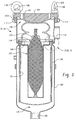
- FIGURE 3 is a cross-section of the filter unit of the system of FIGURES 1 and 2 ;
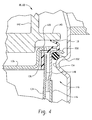
- FIGURE 4 is an enlarged view of a portion of FIGURE 3 ;
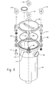
- FIGURE 5 is an exploded view of the housing of the filter unit of FIGURE 3 ;
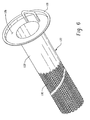
- FIGURE 6 is an isometric view of the filter basket of the system of the present disclosure.
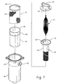
- FIGURE 7 is an exploded view of the filter unit of FIGURE 3 ;
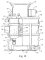
- FIGURE 8 is an exonometric view of the system of FIGURE 2 mounted on a wheeled cart;
- FIGURE 9 is an axonometric view of the cart of FIGURE 8 ;
- FIGURE 10 is a front view of the system of FIGURE 8 ;
- FIGURE 11 is a right side view of the system of FIGURE 8 ;
- FIGURE 12 is a left side view of the system of FIGURE 8 ;
- FIGURE 13 is a rear view of the system of FIGURE 8 .
- one basic version of the system is indicated generally at 10 and includes a quick disconnect fitting 12 adapted for connection to a fire department connection such as that found on a sprinkler system or fire hydrant.
- the quick disconnect 12 is connected through a reducer 13 to the inlet of a strainer 16 which has the outlet thereof connected to the inlet of a pump 18 which has its outlet connected to the inlet of a filtration unit indicated generally at 20.
- the pump receives power through an operator's switch 22 connected to an external source of electrical power such as 115 volts ac single phase as indicated in dashed line in FIG. 1 at 25.
- a Power - On pilot light 24 may be connected in parallel with the switch 22.
- the outlet of the filtration unit 20 discharges through a quick disconnect fitting 26 which is adapted for connection to a hose or line to discharge the filtered waste water effluent from the unit 20 as denoted by reference numeral 28 in FIG. 1 and which may be a storm drain.
- FIG. 2 another version of the system of the present disclosure is indicated generally at 40 and has a quick disconnect fitting 42 adapted for connection to a sprinkler nozzle discharge 43 and provides wastewater flow through a butterfly valve 44 to a quick disconnect coupling 46 connected to the inlet of a reservoir 48.
- the reservoir has its outlet connected through a quick disconnect coupling 50 to another quick disconnect coupling 52 which connects through a pipe reducer 54 to the inlet of a strainer 56.
- the effluent of the strainer is connected to the inlet of a pump 58 which has its outlet connected to the inlet of a filtration unit, indicated generally at 60, which has its outlet connected to a quick disconnect coupling 62 to discharge filtrate at 63 such as to a wastewater drain.
- the pump receives electrical power from a power supply such as 115 volts ac single phase supply 65 through a manually operated switch 64 which may have in parallel electrically therewith a pilot light 66 for indicating power connection to the system. If desired a pressure indicator denoted "PI" may be connected to the inlet of the butterfly valve.
- a power supply such as 115 volts ac single phase supply 65
- a pilot light 66 for indicating power connection to the system.
- a pressure indicator denoted "PI" may be connected to the inlet of the butterfly valve.
- FIG. 1 is particularly suitable for connection directly to a fire hydrant drain in view of the proximity of hydrants to storm drains; and, the system of FIG. 2 has been found particularly satisfactory for in situ filtration of wastewater from a fire suppression sprinkler system where it may be necessary to drain the system in a building and transport the wastewater to a storm drain for fitting and discharge.
- the filtration units 20, 60 are illustrated typically in greater detail in which the system has a housing 100 having a generally cylindrical tubular configuration with an open end indicated generally at 102 which is closed by a removable lid 104 secured to a suitable expedient such as swing bolts 106, 108 pivotally mounted respectively to a flange 110 disposed about the open end of the housing respectively on bolts 112, 114.
- the swing bolts may be secured in position by suitable ring nuts 118, 120.
- Housing 100 defines a filtering cavity 116 which has disposed therein a basket indicated generally at 122 which has received in the open end thereof a cartridge indicated generally at 124 formed of a sleeve 123 of porous woven mesh filled with particulate polymer material.
- the sleeve may be formed of .25 mm monofilament polyethylene terephthalate woven mesh.
- the sleeve has an O.D. in the range of about 38-89 mm and a wall thickness of about 0.635 mm.
- the monofilament in the exemplary version has a tensile strength D-2265 of about 7.5 pounds.
- the sleeve 123 may be omitted and the particulate or granular filtering material dispersed directly in the basket 122.
- the basket 122 has a radially outward extending annular flange 126 formed about the open end thereof which flange has an axially upwardly and outwardly extending lip 128.
- the closed end portion comprising the downstream half of the basket 122 has perforations 130 formed therein.
- the upper half of basket 122 on portion 132 adjacent flange 126 is imperforate.
- the basket may be formed of stainless steel or other suitable material.
- the sleeve of cartridge 124 which may be formed of mesh woven from monofilament polyethylene terephthalate material extends longitudinally in the basket into the imperforate portion 132 in FIG. 6 and into the perforated portion 130. If desired, sleeve 123 may be omitted and the particulate or granular material filled directly in the basket 122.
- the basket is surrounded by a bag filter 134 which has at its upper end an annular flange 136 attached thereto, as for example by ultrasonic weldment.
- the flange 136 has an outwardly and upwardly extending portion forming a lip 138 which is in contact with and urged downwardly by a flange 140 provided on a hold down spring 142 which has its upper end registered against and retained by the undersurface of lid 104 as denoted by reference numeral 134 in FIG. 3 .
- the bag filter 134 is surrounded by a second outer perforated basket 146 which is attached to an annular flange 148 having an outwardly extending portion 150 which contacts a resilient annular seal 152, such as an o-ring, for sealing against an annular rib 154 formed in the housing 100 (see FIG. 4 ).
- a resilient annular seal 152 such as an o-ring
- This arrangement thus prevents fluids entering the housing inlet 103 from bypassing the particulate material in cartridge 124 thereby requiring the wastewater to flow through the material in the cartridge 124 and outwardly through the perforations 130 in the downstream or lower portion of the basket 122.
- the effluent of the basket perforations 130 then flows outwardly through the bag filter 134 then through the perforated outer basket 146 and through outlet 105 of the housing 100.
- the outlet 105 is connected to the disconnect fitting 26 of the system 10 of FIG. 1 ; and, in the system 40 of FIG. 2 , it is connected to the outlet disconnect fitting 62.
- the sleeve 124 woven of monofilament material having a diameter expandable in the range of about 38 to 89 mm and has a wall thickness of about 0.63 mm with the monofilament having a tensile strength per ASTM D-2265 of about 7.5 pounds and a specific gravity of about 1.38.
- the basket 122 has a diameter of about 78 mm and has an overall length of about 318 mm and may be formed of corrosion resistant or stainless steel or other suitable material.
- the basket may be formed of different configurations and dimensions commensurate with the configuration of the housing 106 and the amount of particulate polymer material to be encased therein.
- the exemplary version described has been found satisfactory to employ a bag filter capable of filtering particles larger than 1 micron (1 x 10 -6 meters); however, bag filters with different filtering capabilities may be employed.
- the system 40 illustrated in FIG. 2 is shown in a portable version indicated generally at 200.
- the components are mounted on an upright cart indicated generally at 202 having a front set of wheels 204 and handles 203 on the upper end.
- a second auxiliary set of wheels 206 is provided for inclining the cart and a platform 205 is provided for supporting the drum.
- the system 200 includes reservoir 48 which comprises a drum which may have a removable lid 208 and which has inlet fitting 46 connected to valve 44 and quick disconnect fitting 42 for connection to a sprinkler system discharge connection.
- the outlet 50 of the reservoir is connected through quick disconnect fitting 62 to a swivel fitting 210 connected to a pipe 212 which is connected at its opposite end to a second swivel fitting 214 which connects to a quick disconnect 52 at the inlet of the strainer 56.
- the drum is held onto the cart by straps 228 anchored to channels 230 attached to the cart 202.
- Filter unit 60 is retained by straps 232 anchored to channels 230.
- An electrical receptacle box 216 is mounted on a plate 218 provided on the cart; and, box 216 contains the manual switch 64 and the pilot light 66 along with an electrical lead 218 (see FIG. 11 ) for electrical connection thereto from a source of electrical power.
- Strainer 56 has the outlet 220 thereof connected to the inlet 103 of the filtration unit 60.
- the outlet 105 of the filtration unit 60 is connected through quick disconnect coupling 62 to a drain such as a storm water drain (not shown).
- the present disclosure thus describes a filtration system having, in one version, a strainer for connection to a fire department connection for draining fire hydrants or other fluid systems requiring wastewater drain.
- the strainer outlet being connected to a pump which supplies strained fluid to the inlet of a filtration unit.
- the filtration unit includes a housing with a cavity having a basket with the downstream portion or lower portion perforated and having disposed therein a filter cartridge formed of a woven mesh sleeve filled with particulate polymer material for filtering.
- the basket is surrounded by a bag filter which further filters the effluent of the cartridge and which may be encased in an outer basket.
- the effluent of the bag filter is discharged through an outlet in the housing remote from the inlet.
- the strainer has its inlet connected to receive fluid from a reservoir or tank.
- the version including the reservoir is described as mounted on a wheeled cart for portability and is particularly suitable for in situ draining of wastewater from fire suppression sprinkler systems.
Landscapes
- Chemical & Material Sciences (AREA)
- Chemical Kinetics & Catalysis (AREA)
- Filtration Of Liquid (AREA)
Abstract
Description
- This application is related to co-pending application of Mark Anthony Quintel, Application No.
13/086,756, filed April 14, 2011 - The present disclosure relates to filtering of fluids such as wastewater from fire sprinkler systems and fire hydrants prior to discharge of the water into a drain or open body of water in the ecosystem. Currently, environmental regulations require filtration of such wastewater prior to discharge into storm drains.
- It has thus been desired to provide a filtration system for in situ filtering of wastewater from the aforesaid systems at the time of required periodic draining in order to eliminate the necessity of collecting the wastewater in a vessel and transporting it to a stationary filtration facility. Heretofore, portable filtration systems for filtering wastewater drained from such systems have encountered problems with plugging from particles and other foreign matter accumulated in the system to be drained. Thus, it has been desired to provide an improved portable filtering system capable of in situ filtering of wastewater from the system to be drained and rendering the filtrate suitable for discharge into a storm drain.
- The present disclosure describes a filtering system, filter unit and method for filtering wastewater such as drained from a closed system, for example a sprinkler system or fire hydrants and which is capable of being readily transported to the system site and manually positioned for filtering the wastewater in situ. The system employs a strainer for removing large particles and a pump for pumping the strainer effluent through a filtering unit. The filtering unit has a basket filled with particulate polymer material with a downstream portion of the basket perforated to permit outflow of fluid filtration passing through the particulate material. The particulate polymer material may be enclosed in a woven mesh sleeve to facilitate assembly of the filtration unit. The basket is surrounded by a bag filter such that effluent from the polymer particulate material flows outwardly through the basket perforations and subsequently through the bag filter. The effluent of the bag filter is discharged through an outlet in the housing cavity remote from the inlet and to a drain. In one version, the system includes a valve enabling connection of the strainer inlet directly to the system to be drained of wastewater. In another version, a reservoir is provided to accumulate wastewater from the system to be drained; and, the wastewater is pumped from the reservoir through the strainer into the filtration unit. If desired, either of the aforesaid versions of the system may be mounted on a wheeled cart for portability. The version with a reservoir is illustrated and described as mounted on a cart. The cart may be wheeled to the location for draining the system and the system connected to a source of electrical power for operating the pump.
-
FIGURE 1 is a block diagram of the basic version of the system of the present disclosure; -
FIGURE 2 is a block diagram of another version of the system including a reservoir; -
FIGURE 3 is a cross-section of the filter unit of the system ofFIGURES 1 and2 ; -
FIGURE 4 is an enlarged view of a portion ofFIGURE 3 ; -
FIGURE 5 is an exploded view of the housing of the filter unit ofFIGURE 3 ; -
FIGURE 6 is an isometric view of the filter basket of the system of the present disclosure; -
FIGURE 7 is an exploded view of the filter unit ofFIGURE 3 ; -
FIGURE 8 is an exonometric view of the system ofFIGURE 2 mounted on a wheeled cart; -
FIGURE 9 is an axonometric view of the cart ofFIGURE 8 ; -
FIGURE 10 is a front view of the system ofFIGURE 8 ; -
FIGURE 11 is a right side view of the system ofFIGURE 8 ; -
FIGURE 12 is a left side view of the system ofFIGURE 8 ; and, -
FIGURE 13 is a rear view of the system ofFIGURE 8 . - Referring to
FIG. 1 , one basic version of the system is indicated generally at 10 and includes aquick disconnect fitting 12 adapted for connection to a fire department connection such as that found on a sprinkler system or fire hydrant. Thequick disconnect 12 is connected through a reducer 13 to the inlet of astrainer 16 which has the outlet thereof connected to the inlet of apump 18 which has its outlet connected to the inlet of a filtration unit indicated generally at 20. The pump receives power through an operator'sswitch 22 connected to an external source of electrical power such as 115 volts ac single phase as indicated in dashed line inFIG. 1 at 25. If desired, a Power - Onpilot light 24 may be connected in parallel with theswitch 22. The outlet of thefiltration unit 20 discharges through aquick disconnect fitting 26 which is adapted for connection to a hose or line to discharge the filtered waste water effluent from theunit 20 as denoted byreference numeral 28 inFIG. 1 and which may be a storm drain. - Referring to
FIG. 2 , another version of the system of the present disclosure is indicated generally at 40 and has aquick disconnect fitting 42 adapted for connection to asprinkler nozzle discharge 43 and provides wastewater flow through abutterfly valve 44 to aquick disconnect coupling 46 connected to the inlet of areservoir 48. The reservoir has its outlet connected through aquick disconnect coupling 50 to anotherquick disconnect coupling 52 which connects through apipe reducer 54 to the inlet of astrainer 56. The effluent of the strainer is connected to the inlet of apump 58 which has its outlet connected to the inlet of a filtration unit, indicated generally at 60, which has its outlet connected to aquick disconnect coupling 62 to discharge filtrate at 63 such as to a wastewater drain. The pump receives electrical power from a power supply such as 115 volts acsingle phase supply 65 through a manually operatedswitch 64 which may have in parallel electrically therewith apilot light 66 for indicating power connection to the system. If desired a pressure indicator denoted "PI" may be connected to the inlet of the butterfly valve. - It will be understood that the system of
FIG. 1 is particularly suitable for connection directly to a fire hydrant drain in view of the proximity of hydrants to storm drains; and, the system ofFIG. 2 has been found particularly satisfactory for in situ filtration of wastewater from a fire suppression sprinkler system where it may be necessary to drain the system in a building and transport the wastewater to a storm drain for fitting and discharge. - Referring to
FIGS. 3-7 thefiltration units housing 100 having a generally cylindrical tubular configuration with an open end indicated generally at 102 which is closed by aremovable lid 104 secured to a suitable expedient such asswing bolts flange 110 disposed about the open end of the housing respectively onbolts suitable ring nuts -
Housing 100 defines afiltering cavity 116 which has disposed therein a basket indicated generally at 122 which has received in the open end thereof a cartridge indicated generally at 124 formed of asleeve 123 of porous woven mesh filled with particulate polymer material. The sleeve may be formed of .25 mm monofilament polyethylene terephthalate woven mesh. In one version, the sleeve has an O.D. in the range of about 38-89 mm and a wall thickness of about 0.635 mm. The monofilament in the exemplary version has a tensile strength D-2265 of about 7.5 pounds. In the present practice, it has been found satisfactory to fill the sleeve ofcartridge 124 with particulate polymer material sold under the name Smart Sponge® Plus obtainable from AbTech Industries Inc. 4110 North Scottsdale Road, Suite 235, Scottsdale, AZ 85251, Manufacturer's Part No. ACX-10-N-PLUS. The particular polymer material may be treated with an organosilane antimicrobial compound to provide resistance to coliform bacteria. However, if desired, other particulate or granular filtering material may be employed. - Alternatively, the
sleeve 123 may be omitted and the particulate or granular filtering material dispersed directly in thebasket 122. Referring toFIG. 6 , thebasket 122 has a radially outward extendingannular flange 126 formed about the open end thereof which flange has an axially upwardly and outwardly extendinglip 128. Referring toFIG. 6 , the closed end portion comprising the downstream half of thebasket 122 hasperforations 130 formed therein. The upper half ofbasket 122 onportion 132adjacent flange 126 is imperforate. In the exemplary version illustrated, the basket may be formed of stainless steel or other suitable material. - It will be understood from
FIGS. 3 and6 , that the sleeve ofcartridge 124, which may be formed of mesh woven from monofilament polyethylene terephthalate material extends longitudinally in the basket into theimperforate portion 132 inFIG. 6 and into theperforated portion 130. If desired,sleeve 123 may be omitted and the particulate or granular material filled directly in thebasket 122. - Referring to
FIGS. 3 ,4 and7 , the basket is surrounded by abag filter 134 which has at its upper end anannular flange 136 attached thereto, as for example by ultrasonic weldment. Theflange 136 has an outwardly and upwardly extending portion forming alip 138 which is in contact with and urged downwardly by aflange 140 provided on a hold downspring 142 which has its upper end registered against and retained by the undersurface oflid 104 as denoted byreference numeral 134 inFIG. 3 . Referring again toFIGS. 3 ,4 and7 , thebag filter 134 is surrounded by a second outerperforated basket 146 which is attached to anannular flange 148 having an outwardly extendingportion 150 which contacts a resilientannular seal 152, such as an o-ring, for sealing against anannular rib 154 formed in the housing 100 (seeFIG. 4 ). Thus, as shown inFIG. 4 ,basket flange 128 is retained against theflange 136 of the bag filter which is pressed against theflange 150 by contact oflip 138 with the hold downflange 140. This arrangement thus prevents fluids entering thehousing inlet 103 from bypassing the particulate material incartridge 124 thereby requiring the wastewater to flow through the material in thecartridge 124 and outwardly through theperforations 130 in the downstream or lower portion of thebasket 122. The effluent of thebasket perforations 130 then flows outwardly through thebag filter 134 then through the perforatedouter basket 146 and throughoutlet 105 of thehousing 100. - The
outlet 105 is connected to the disconnect fitting 26 of thesystem 10 ofFIG. 1 ; and, in thesystem 40 ofFIG. 2 , it is connected to the outlet disconnect fitting 62. - In the present practice, it has been found satisfactory to have the
sleeve 124 woven of monofilament material having a diameter expandable in the range of about 38 to 89 mm and has a wall thickness of about 0.63 mm with the monofilament having a tensile strength per ASTM D-2265 of about 7.5 pounds and a specific gravity of about 1.38. However, other configurations of woven mesh and sizes may be employed to accommodate the desired amount of particulate polymer material to be employed. In the present practice, thebasket 122 has a diameter of about 78 mm and has an overall length of about 318 mm and may be formed of corrosion resistant or stainless steel or other suitable material. It will be understood that the basket may be formed of different configurations and dimensions commensurate with the configuration of thehousing 106 and the amount of particulate polymer material to be encased therein. In the present practice, the exemplary version described has been found satisfactory to employ a bag filter capable of filtering particles larger than 1 micron (1 x 10⁻⁶ meters); however, bag filters with different filtering capabilities may be employed. - Referring to
FIGS. 8-13 , thesystem 40 illustrated inFIG. 2 is shown in a portable version indicated generally at 200. The components are mounted on an upright cart indicated generally at 202 having a front set ofwheels 204 and handles 203 on the upper end. A second auxiliary set ofwheels 206 is provided for inclining the cart and aplatform 205 is provided for supporting the drum. Thesystem 200 includesreservoir 48 which comprises a drum which may have aremovable lid 208 and which has inlet fitting 46 connected tovalve 44 and quick disconnect fitting 42 for connection to a sprinkler system discharge connection. Theoutlet 50 of the reservoir is connected through quick disconnect fitting 62 to a swivel fitting 210 connected to apipe 212 which is connected at its opposite end to a second swivel fitting 214 which connects to aquick disconnect 52 at the inlet of thestrainer 56. The drum is held onto the cart bystraps 228 anchored tochannels 230 attached to thecart 202.Filter unit 60 is retained bystraps 232 anchored tochannels 230. - An
electrical receptacle box 216 is mounted on aplate 218 provided on the cart; and,box 216 contains themanual switch 64 and thepilot light 66 along with an electrical lead 218 (seeFIG. 11 ) for electrical connection thereto from a source of electrical power. -
Strainer 56 has theoutlet 220 thereof connected to theinlet 103 of thefiltration unit 60. Theoutlet 105 of thefiltration unit 60 is connected throughquick disconnect coupling 62 to a drain such as a storm water drain (not shown). The present disclosure thus describes a filtration system having, in one version, a strainer for connection to a fire department connection for draining fire hydrants or other fluid systems requiring wastewater drain. The strainer outlet being connected to a pump which supplies strained fluid to the inlet of a filtration unit. The filtration unit includes a housing with a cavity having a basket with the downstream portion or lower portion perforated and having disposed therein a filter cartridge formed of a woven mesh sleeve filled with particulate polymer material for filtering. The basket is surrounded by a bag filter which further filters the effluent of the cartridge and which may be encased in an outer basket. The effluent of the bag filter is discharged through an outlet in the housing remote from the inlet. In a second version, the strainer has its inlet connected to receive fluid from a reservoir or tank. The version including the reservoir is described as mounted on a wheeled cart for portability and is particularly suitable for in situ draining of wastewater from fire suppression sprinkler systems. - The exemplary embodiments have been described with reference to the drawings. Obviously, modifications and alterations will occur to others upon reading and understanding the preceding detailed description. It is intended that the exemplary embodiments be construed as including all such modifications and alterations insofar as they come within the scope of the appended claims or the equivalents thereof.
-
- 1. A filtering system for wastewater comprising:
- (a) a particle strainer;
- (b) a pump operatively connected to receive strainer effluent at its inlet;
- (c) a primary filter having particulate polymeric material dispersed therein and operatively connected to receive effluent from the pump; and,
- (d) a bag filter disposed about the primary filter and operatively receiving effluent from the primary filter,
- 2. The system of 1, wherein the housing has a removable closure for enabling replacement of the primary filter and bag filter.
- 3. The filtering system defined in 1, wherein the primary filter includes shredded polymeric material.
- 4. The system of 1, wherein the bag filter is operative to filter particles larger than 1 micron (1 x 10⁻⁶ meters).
- 5. The system of 1, wherein the primary filter includes a basket having an imperforate portion proximate the open end thereof and having a perforated portion downstream of the imperforate portion with the polymeric material disposed in the imperforate and perforate portions.
- 6. The system of 1, wherein the primary filter includes anti-microbial material.
- 7. The system of 1, wherein the filter includes an organosilane antimicrobial material.
- 8. The system of 1, wherein the housing, strainer primary filter and bag filter are mounted on a wheeled cart for portability.
- 9. A method of filtering wastewater comprising:
- (a) connecting a strainer inlet to a source of wastewater;
- (b) flowing wastewater through the strainer with a pump;
- (c) pumping effluent from the strainer through a primary filter including particulate polymeric material; and,
- (d) disposing a bag filter about the primary filter and flowing effluent from the primary filter through the bag filter; and,
- (e) disposing the primary filter and bag filter in a housing and connecting the housing to receive effluent from the pump.
- 10. The method defined in 9, further comprising:
- mounting the strainer, pump and housing on a wheeled cart for portability.
- 11. The method of 9, wherein the step of pumping water through a primary filter includes disposing the particulate polymeric material in a basket having an impervious portion proximate the open end and a perforated portion downstream of the impervious portion.
- 12. The method defined in 9, wherein the step of pumping strainer effluent includes pumping strainer effluent through a primary filter of particulate polyethylene material.
- 13. The method defined in 9, wherein the step of flowing primary filter effluent includes flowing primary filter effluent through a bag filter capable of filtering particles greater than 1 micron (1 x 10⁻⁶ meters).
- 14. The method defined in 9, wherein the step of flowing strainer effluent includes flowing through a filter including shredded polymeric material.
- 15. The method defined in 9, wherein the step of flowing strainer effluent includes flowing through a primary filter including particulate polyethylene material.
- 16. A filter assembly for wastewater comprising:
- (a) a housing defining a filtering chamber having an opening for receiving filtering material, a lid operative for closing the opening, an inlet proximate the opening and an outlet distal the inlet;
- (b) a filter basket having an imperforate portion proximate the open end and a perforate portion downstream of the imperforate portion, the basket removably received in the chamber through the opening in the filtering chamber;
- (c) a filter cartridge comprising a flexible porous sleeve filled with particulate polymer material and closed at its end thereof, the cartridge being disposed in the basket and extending into the imperforate and into the perforate portion;
- (d) a bag filter disposed about the basket and removable with the basket, wherein wastewater received through the inlet Is caused to flow sequentially through the cartridge, outwardly through the perforate portion of the basket and through the bag filter to the outlet.
- 17. The assembly of 16, wherein the primary filter includes a woven sleeve disposed about the particulate polymer material
- 18. The assembly of 17, wherein the sleeve is formed of woven monofilament.
- 19. The filtering assembly of 16, wherein the bag filter is capable of filtering particles of at least 1 micron (2 x 10⁻⁶ meters).
- 20. The filtering assembly of 16, further comprising a spring clamp for retaining the basket and cartridge in the chamber downstream of the inlet.
- 21. The filtering assembly of 16, further comprising a porous outer retainer basket surrounding the bag filter.
- 22. The filtering assembly of 16, wherein the basket includes an annular flange with an annular seal for preventing wastewater entering the chamber from the inlet from bypassing the filter cartridge.
- 23. The filtering assembly of 16, wherein the bag filter has an annular flange attached thereto and an annular seal sealing the flange on a sealing surface formed in the chamber.
- 24. The filtering assembly of 16, further comprising an outer retain basket disposed over the bag filter having an annular flange sealed on an annular sealing surface in the chamber by an o-ring operative for preventing flow from the inlet from by-passing the filter cartridge.
- 25. The filtering assembly of 16, wherein the sleeve is formed of woven mesh polymer material.
- 26. The filtering assembly of 16, wherein the housing comprises a pressure vessel with an annular sealing surface about the opening; and, the lid is releasably secured thereon and sealed with an annular seal.
- 27. The filtering assembly of 26, wherein the lid is releasably secured by swing bolts.
- 28. The filtering assembly of 16, further comprising a wastewater reservoir with the strainer connected to receive water from the reservoir.
- 29. The system of 28 wherein the reservoir, strainer, pump and housing are on a wheeled cart for portability.
Claims (10)
- A filtering system for wastewater comprising:(a) a particle strainer (16);(b) a pump (18) operatively connected to receive strainer effluent at its inlet;(c) a primary filter (124) having particulate polymeric material dispersed therein and operatively connected to receive effluent from the pump; and,(d) a bag filter (134) disposed about the primary filter and operatively receiving effluent from the primary filter,wherein the primary filter and bag filter are disposed in a housing (100) and the strainer has an inlet (103) for connection to a source of wastewater.
- The system of claim 1, wherein the bag filter (134) is operative to filter particles larger than 1 micron (1 x 10⁻⁶ meters).
- The system of claim 1, wherein the primary filter includes a basket (122) having an imperforate portion (132) proximate the open end thereof and having a perforated portion (130) downstream of the imperforate portion with the polymeric material disposed in the imperforate and perforate portions.
- The system of claim 1, wherein the primary filter includes anti-microbial material.
- A method of filtering wastewater comprising:(a) connecting a strainer inlet (103) to a source of wastewater;(b) flowing wastewater through the strainer with a pump (18);(c) pumping effluent from the strainer through a primary filter (124) including particulate polymeric material; and,(d) disposing a bag filter (134) about the primary filter and flowing effluent from the primary filter through the bag filter; and,(e) disposing the primary filter and bag filter in a housing (100) and connecting the housing to receive effluent from the pump.
- The method of claim 5, wherein the step of pumping water through a primary filter includes disposing the particulate polymeric material in a basket (122) having an impervious portion (132) proximate the open end and a perforated portion (130) downstream of the impervious portion.
- A filter assembly for wastewater comprising:(a) a housing (100) defining a filtering chamber (116) having an opening (102) for receiving filtering material (124), a lid (104) operative for closing the opening, an inlet (103) proximate the opening and an outlet (105) distal the inlet;(b) a filter basket (122) having an imperforate (132) portion proximate the open end and a perforate portion (130) downstream of the imperforate portion, the basket removably received in the chamber through the opening in the filtering chamber;(c) a filter cartridge (124) comprising a flexible porous sleeve filled with particulate polymer material and closed at its end thereof, the cartridge being disposed in the basket and extending into the imperforate and into the perforate portion;(d) a bag filter (134) disposed about the basket and removable with the basket, wherein wastewater received through the inlet is caused to flow sequentially through the cartridge, outwardly through the perforate portion of the basket and through the bag filter to the outlet.
- The assembly of claim 7, wherein the primary filter includes a woven sleeve disposed about the particulate polymer material
- The filtering assembly of claim 7, wherein the bag filter is capable of filtering particles of at least 1 micron (2 x 10⁻⁶ meters).
- The filtering assembly of claim 7, wherein the sleeve is formed of woven mesh polymer material.
Applications Claiming Priority (1)
| Application Number | Priority Date | Filing Date | Title |
|---|---|---|---|
| US13/086,699 US8323493B2 (en) | 2011-04-14 | 2011-04-14 | Fluid filter |
Publications (1)
| Publication Number | Publication Date |
|---|---|
| EP2510993A1 true EP2510993A1 (en) | 2012-10-17 |
Family
ID=45999543
Family Applications (1)
| Application Number | Title | Priority Date | Filing Date |
|---|---|---|---|
| EP12002610A Withdrawn EP2510993A1 (en) | 2011-04-14 | 2012-04-13 | Fluid filter and method of filtering |
Country Status (2)
| Country | Link |
|---|---|
| US (1) | US8323493B2 (en) |
| EP (1) | EP2510993A1 (en) |
Cited By (1)
| Publication number | Priority date | Publication date | Assignee | Title |
|---|---|---|---|---|
| CN119461529A (en) * | 2024-11-25 | 2025-02-18 | 江西杰凯流体科技有限公司 | A small filter that is easy to clean |
Families Citing this family (17)
| Publication number | Priority date | Publication date | Assignee | Title |
|---|---|---|---|---|
| US20120261329A1 (en) * | 2011-04-14 | 2012-10-18 | Eaton Corporation | Filter cartridge for use in a fluid filter housing and method of making same |
| US9914076B2 (en) * | 2013-07-15 | 2018-03-13 | Clarus Fluid Intelligence, Llc | Convertible filtration system |
| USD742997S1 (en) | 2014-04-10 | 2015-11-10 | Unger Marketing International, Llc | Water purification media device |
| US11911720B2 (en) | 2014-04-10 | 2024-02-27 | Unger Marketing International, Llc | Fluid purification device |
| USD740915S1 (en) | 2014-04-10 | 2015-10-13 | Unger Marketing International, Llc | Water purification device |
| EP3696146B1 (en) | 2014-04-10 | 2022-09-07 | Unger Marketing International, LLC | Filter bag pure water systems |
| US10661203B2 (en) * | 2014-09-05 | 2020-05-26 | Fred Geyer | Enhanced liquid filter bag |
| US11148082B2 (en) | 2015-04-10 | 2021-10-19 | Unger Marketing International, Llc | Fluid purification device |
| US11154800B2 (en) | 2015-04-10 | 2021-10-26 | Unger Marketing International, Llc | Fluid purification device |
| USD849886S1 (en) | 2017-08-28 | 2019-05-28 | Unger Marketing International, Llc | Water purification device |
| US9982417B1 (en) * | 2015-09-18 | 2018-05-29 | Erik L. Humble | Water delivery apparatus |
| US20190224592A1 (en) * | 2018-01-19 | 2019-07-25 | Pristine Environmental, LLC | Portable particulate filtering system and method |
| USD907742S1 (en) | 2018-03-07 | 2021-01-12 | Unger Marketing International, Llc | Water purification media device |
| USD958928S1 (en) | 2018-11-01 | 2022-07-26 | Unger Marketing International, Llc | Water purification media device |
| DE102020111555B4 (en) | 2020-04-28 | 2022-10-13 | Manfred Völker | water treatment module |
| USD995565S1 (en) * | 2021-09-10 | 2023-08-15 | Cmotion Technologies Limited | Liquid cooling pump set |
| US12239924B2 (en) * | 2023-01-26 | 2025-03-04 | Mechanical Manufacturing Corporation | Collar having modular parts for supporting stratified filtration |
Citations (3)
| Publication number | Priority date | Publication date | Assignee | Title |
|---|---|---|---|---|
| GB654012A (en) * | 1948-10-04 | 1951-05-30 | Arthur James Simpson | Improvements in or relating to filtering devices |
| US4913815A (en) * | 1987-02-24 | 1990-04-03 | David A. Shulda Enterprises, Inc. | Concentric dual bag filter apparatus with contained media |
| US6180010B1 (en) * | 1998-03-24 | 2001-01-30 | Mother Environmental Systems, Inc. | Removal of organic contaminants from an aqueous phase using filtration media infused with an absorbent composition |
Family Cites Families (8)
| Publication number | Priority date | Publication date | Assignee | Title |
|---|---|---|---|---|
| US2633990A (en) * | 1953-04-07 | Filxeking device | ||
| US3478873A (en) * | 1965-03-03 | 1969-11-18 | Laval Turbine | Method and apparatus for separation of tramp oil from oil-in-water emulsions |
| US3544457A (en) * | 1968-03-28 | 1970-12-01 | Ethyl Corp | Process and apparatus for fluid treatment |
| US3631987A (en) * | 1969-10-24 | 1972-01-04 | Peter A Cattano Sr | Swimming pool water clarifier |
| US4419240A (en) * | 1982-07-30 | 1983-12-06 | Rosaen Borje O | Fluid filtering device |
| US7967992B2 (en) * | 2005-01-25 | 2011-06-28 | Ricura Technologies, Llc | Method and device incorporating granular particles and disc-shaped plastic pellets for filtering water |
| US7459074B1 (en) | 2007-07-27 | 2008-12-02 | Sanchez Robert M | Waste water filtering system |
| US7438820B1 (en) | 2007-07-27 | 2008-10-21 | Sanchez Robert M | Waste water filtering method and system |
-
2011
- 2011-04-14 US US13/086,699 patent/US8323493B2/en active Active
-
2012
- 2012-04-13 EP EP12002610A patent/EP2510993A1/en not_active Withdrawn
Patent Citations (3)
| Publication number | Priority date | Publication date | Assignee | Title |
|---|---|---|---|---|
| GB654012A (en) * | 1948-10-04 | 1951-05-30 | Arthur James Simpson | Improvements in or relating to filtering devices |
| US4913815A (en) * | 1987-02-24 | 1990-04-03 | David A. Shulda Enterprises, Inc. | Concentric dual bag filter apparatus with contained media |
| US6180010B1 (en) * | 1998-03-24 | 2001-01-30 | Mother Environmental Systems, Inc. | Removal of organic contaminants from an aqueous phase using filtration media infused with an absorbent composition |
Cited By (1)
| Publication number | Priority date | Publication date | Assignee | Title |
|---|---|---|---|---|
| CN119461529A (en) * | 2024-11-25 | 2025-02-18 | 江西杰凯流体科技有限公司 | A small filter that is easy to clean |
Also Published As
| Publication number | Publication date |
|---|---|
| US8323493B2 (en) | 2012-12-04 |
| US20120261359A1 (en) | 2012-10-18 |
Similar Documents
| Publication | Publication Date | Title |
|---|---|---|
| US8323493B2 (en) | Fluid filter | |
| CA3000427C (en) | Household wastewater filter | |
| EP3044165B1 (en) | Nozzle-brush automatic cleaning filter with motor reducer | |
| CA2797396C (en) | Site drainer | |
| US9228575B2 (en) | Sealed and self-contained tankless water heater flushing system | |
| CN101765450B (en) | Wastewater Filtration System | |
| JP2011005419A (en) | Y-type strainer and pressure tank | |
| CA3125098A1 (en) | Regenerative media filter and related methods | |
| US20110068062A1 (en) | System for removing contaminants from a water circulation stream | |
| US5407562A (en) | Water reclaiming apparatus | |
| US2878938A (en) | Swimming pool filter | |
| CN107030075B (en) | Automatic water and sewage separation system of collection waste residue | |
| CN211813734U (en) | Site environment investigation monitoring well washing filter equipment | |
| CN112138437A (en) | filter unit | |
| US20140306591A1 (en) | Wall-mounted kitchen-cabinet with storage of non-potable water out of reverse osmosis (RO) water treating machine | |
| KR101081709B1 (en) | Apparatus for filtering foreign body in waste water with opening and closing type | |
| JP2016104463A (en) | Water treatment equipment | |
| US20050205479A1 (en) | Greywater recycling apparatus | |
| EP3810554A1 (en) | Water treatment system and method for a wheel washing arrangement | |
| CN212954614U (en) | Pre-filter with built-in scale inhibitor | |
| KR101518973B1 (en) | Equipped with a filter cartridge drain sewage | |
| RU167817U1 (en) | CARTRIDGE FILTER FOR WATER CLEANING | |
| AU2014330107A1 (en) | Filtration system and method for filtering a liquid | |
| US20070125699A1 (en) | Filter Device | |
| KR200484809Y1 (en) | A Underground Water Filtering Device |
Legal Events
| Date | Code | Title | Description |
|---|---|---|---|
| PUAI | Public reference made under article 153(3) epc to a published international application that has entered the european phase |
Free format text: ORIGINAL CODE: 0009012 |
|
| AK | Designated contracting states |
Kind code of ref document: A1 Designated state(s): AL AT BE BG CH CY CZ DE DK EE ES FI FR GB GR HR HU IE IS IT LI LT LU LV MC MK MT NL NO PL PT RO RS SE SI SK SM TR |
|
| AX | Request for extension of the european patent |
Extension state: BA ME |
|
| 17P | Request for examination filed |
Effective date: 20130416 |
|
| GRAP | Despatch of communication of intention to grant a patent |
Free format text: ORIGINAL CODE: EPIDOSNIGR1 |
|
| RIC1 | Information provided on ipc code assigned before grant |
Ipc: B01D 29/56 20060101ALI20130920BHEP Ipc: B01D 36/02 20060101ALI20130920BHEP Ipc: B01D 24/04 20060101AFI20130920BHEP Ipc: B01D 29/27 20060101ALI20130920BHEP |
|
| INTG | Intention to grant announced |
Effective date: 20131010 |
|
| STAA | Information on the status of an ep patent application or granted ep patent |
Free format text: STATUS: THE APPLICATION IS DEEMED TO BE WITHDRAWN |
|
| 18D | Application deemed to be withdrawn |
Effective date: 20140221 |