EP2510317B1 - Flowmeter and method - Google Patents
Flowmeter and method Download PDFInfo
- Publication number
- EP2510317B1 EP2510317B1 EP10776916.8A EP10776916A EP2510317B1 EP 2510317 B1 EP2510317 B1 EP 2510317B1 EP 10776916 A EP10776916 A EP 10776916A EP 2510317 B1 EP2510317 B1 EP 2510317B1
- Authority
- EP
- European Patent Office
- Prior art keywords
- transducer
- pipe
- tube
- upstream
- downstream
- Prior art date
- Legal status (The legal status is an assumption and is not a legal conclusion. Google has not performed a legal analysis and makes no representation as to the accuracy of the status listed.)
- Active
Links
Images
Classifications
-
- G—PHYSICS
- G01—MEASURING; TESTING
- G01F—MEASURING VOLUME, VOLUME FLOW, MASS FLOW OR LIQUID LEVEL; METERING BY VOLUME
- G01F1/00—Measuring the volume flow or mass flow of fluid or fluent solid material wherein the fluid passes through a meter in a continuous flow
- G01F1/66—Measuring the volume flow or mass flow of fluid or fluent solid material wherein the fluid passes through a meter in a continuous flow by measuring frequency, phase shift or propagation time of electromagnetic or other waves, e.g. using ultrasonic flowmeters
-
- G—PHYSICS
- G01—MEASURING; TESTING
- G01F—MEASURING VOLUME, VOLUME FLOW, MASS FLOW OR LIQUID LEVEL; METERING BY VOLUME
- G01F1/00—Measuring the volume flow or mass flow of fluid or fluent solid material wherein the fluid passes through a meter in a continuous flow
- G01F1/66—Measuring the volume flow or mass flow of fluid or fluent solid material wherein the fluid passes through a meter in a continuous flow by measuring frequency, phase shift or propagation time of electromagnetic or other waves, e.g. using ultrasonic flowmeters
- G01F1/662—Constructional details
-
- G—PHYSICS
- G01—MEASURING; TESTING
- G01F—MEASURING VOLUME, VOLUME FLOW, MASS FLOW OR LIQUID LEVEL; METERING BY VOLUME
- G01F1/00—Measuring the volume flow or mass flow of fluid or fluent solid material wherein the fluid passes through a meter in a continuous flow
- G01F1/66—Measuring the volume flow or mass flow of fluid or fluent solid material wherein the fluid passes through a meter in a continuous flow by measuring frequency, phase shift or propagation time of electromagnetic or other waves, e.g. using ultrasonic flowmeters
- G01F1/667—Arrangements of transducers for ultrasonic flowmeters; Circuits for operating ultrasonic flowmeters
-
- G—PHYSICS
- G01—MEASURING; TESTING
- G01P—MEASURING LINEAR OR ANGULAR SPEED, ACCELERATION, DECELERATION, OR SHOCK; INDICATING PRESENCE, ABSENCE, OR DIRECTION, OF MOVEMENT
- G01P5/00—Measuring speed of fluids, e.g. of air stream; Measuring speed of bodies relative to fluids, e.g. of ship, of aircraft
- G01P5/24—Measuring speed of fluids, e.g. of air stream; Measuring speed of bodies relative to fluids, e.g. of ship, of aircraft by measuring the direct influence of the streaming fluid on the properties of a detecting acoustical wave
-
- Y—GENERAL TAGGING OF NEW TECHNOLOGICAL DEVELOPMENTS; GENERAL TAGGING OF CROSS-SECTIONAL TECHNOLOGIES SPANNING OVER SEVERAL SECTIONS OF THE IPC; TECHNICAL SUBJECTS COVERED BY FORMER USPC CROSS-REFERENCE ART COLLECTIONS [XRACs] AND DIGESTS
- Y10—TECHNICAL SUBJECTS COVERED BY FORMER USPC
- Y10T—TECHNICAL SUBJECTS COVERED BY FORMER US CLASSIFICATION
- Y10T29/00—Metal working
- Y10T29/49—Method of mechanical manufacture
- Y10T29/494—Fluidic or fluid actuated device making
-
- Y—GENERAL TAGGING OF NEW TECHNOLOGICAL DEVELOPMENTS; GENERAL TAGGING OF CROSS-SECTIONAL TECHNOLOGIES SPANNING OVER SEVERAL SECTIONS OF THE IPC; TECHNICAL SUBJECTS COVERED BY FORMER USPC CROSS-REFERENCE ART COLLECTIONS [XRACs] AND DIGESTS
- Y10—TECHNICAL SUBJECTS COVERED BY FORMER USPC
- Y10T—TECHNICAL SUBJECTS COVERED BY FORMER US CLASSIFICATION
- Y10T29/00—Metal working
- Y10T29/49—Method of mechanical manufacture
- Y10T29/49826—Assembling or joining
Definitions
- the present invention is related to a flowmeter for detecting fluid flow rates in a pipe having a tube with a channel disposed in the pipe through which fluid in the pipe flows and plane waves generated by an upstream ultrasonic transducer and a downstream ultrasonic transducer propagate.
- the present invention is related to a flowmeter for detecting fluid flow rates in a pipe having a tube with a channel disposed in the pipe through which fluid in the pipe flows and plane waves generated by an upstream ultrasonic transducer and a downstream ultrasonic transducer propagate, where the tube is made of a sound absorbing material so that essentially all non-fluid paths of sound are absorbed.
- the current ultrasonic flow meter arrangement uses two transducers at opposing ends of a pipe where one is upstream from the fluid flow and other is downstream from the fluid flow, both transducers transmit and receive signals. Each transducer generates plane waves into the fluid and surrounding pipe wall. The difference in transit times between the upstream and downstream signal is used to calculate the flow rate. Since sound travels faster in the pipe wall than in the fluid medium, the receiving transducer has noise because the sound enters the pipe and arrives at a time preceding the sound that travels in the liquid. The noise level is significant because it reduces the accuracy of the flow measurement and results in a poor or no measurement at low flow rates.
- polymers with scattering fillers such as metal or glass or microspheres
- polymers with scattering fillers are used as backing masses for ultrasonic transducers.
- the use of an attenuative backing mass improves the bandwidth of the transmitted ultrasound signal of a transducer by absorbing the sound from the back side of the transducer and not allowing reflections to occur.
- Polymers with scattering fillers it is believed, have never been used as pipe wall sound attenuators in the use of an ultrasonic transit time flow measurement.
- EP 0202583 describes a flow meter of axially symmetrical design, incorporating electroacoustic transducers and a phase-difference evaluation system for each of two transmission bursts which are transmitted in or against the direction of flow respectively.
- the measurement section is formed by a bore in a replaceable insert head.
- EP 1279368 describes a device for measuring the flow velocity and the molar mass of gases or gas mixtures in medical applications using ultrasound time of flight measurements.
- the device comprises a measurement tube with two ultrasound transducers that are separated by membranes from the measurement tube. The membranes form a gas tight seal with the tube and the transducers are flush with the seals.
- US 4003252 describes a fluid flowmeter comprising an enclosed housing having a fluid inlet and a fluid outlet; a liner having an inner wall surface positioned within the housing, the liner being fabricated from a material providing acoustical damping, e.g. polyurethane or rubber foam, and a plurality of acoustic wave transducers secured to the liner in notched portions of the liner inner wall surface.
- a material providing acoustical damping e.g. polyurethane or rubber foam
- the transducers have inner wall surfaces dimensioned to provide with the inner wall surface of the liner a fluid flow conduit substantially devoid of protuberances and cavities
- US 2004/123666 describes a damping material for an ultrasonic transducer system including a spreadable matrix and a plurality of particles is suspended in the spreadable matrix, forming a coating that dissipates ultrasonic energy to dampen noise and reduce crosstalk allowing ultrasonic measurement of gas using clamp-on transducers.
- the present invention is applicable for measuring flow rates, particularly low flow rates, with ultrasonic transit time technology.
- the application is specifically applied to monitoring chemical fluid injection in subsea oil wells.
- the present invention resides in a flowmeter for detecting fluid flow rates in a pipe as defined in claims 1 to 4 and in a method for detecting fluid flow rates in a pipe as defined in claims 5 to 8.
- the invention makes possible a flow measurement at very low flow rates through very small bore pipes.
- a flowmeter 10 for detecting fluid flow rates in a pipe 12.
- the flowmeter 10 comprises a tube 14 having a channel disposed in the pipe 12 through which fluid in the pipe 12 flows.
- the flowmeter 10 comprises an upstream ultrasonic transducer in contact with the pipe 12 and positioned in alignment with the channel so plane waves generated by the upstream transducer 16 propagate through the channel.
- the flowmeter 10 comprises a downstream ultrasonic transducer in contact with the pipe 12 and positioned so plane waves generated by the downstream transducer 18 propagate through the channel and are received by the upstream transducer 16 which produces an upstream transducer 16 signal.
- the downstream transducer 18 receives the plane waves from the upstream transducer 16 and provides a downstream transducer 18 signal.
- the flowmeter 10 comprises a controller 20 in communication with the upstream and downstream transducers 18 which calculate fluid flow rate from the upstream transducer 16 signal and the downstream transducer 18 signal.
- the tube 14 is made of a sound absorbing material so that essentially all non-fluid paths of sound are absorbed.
- the upstream transducer 16 and the downstream transducer 18 extend through the pipe 12 wall and acoustically communicate with the pipe 12 interior.
- the tube 14 forms a seal with the pipe 12 essentially preventing fluid in the pipe 12 leaking around the tube 14.
- the tube 14 is made of a polymer filled with attenuative particles.
- the polymer may be either an epoxy, nylon, PTFE or PEEK (polyaryletheretherketone).
- the particles are either metal, glass microspheres, metal oxide or rubber having a size equal to or smaller than the acoustic wavelength.
- the tube may have a length L and a diameter opening D such that under volume flow conditions where Q > .2 liters/hour, the tube dimensions L/ D 2 are greater than 1385/meters when C > 1400 m/s.
- the present invention pertains to a method for detecting fluid flow rates in a pipe 12.
- the method comprises the steps of flowing fluid through a channel of a tube 14 disposed in the pipe 12.
- the tube 14 is made of a sound absorbing material and wherein the generating plane waves by the upstream transducer 16 step includes the step of generating the plane waves by the upstream transducer 16 so that essentially all non-fluid paths of sound are absorbed by the tube 14, and wherein the generating plane waves by the downstream transducer 18 step includes the step of generating the plane waves by the downstream transducer 18 so that essentially all non-fluid paths of sound are absorbed by the tube 14.
- the generating plane waves by the upstream transducer 16 step includes the step of generating the plane waves by the upstream transducer 16 which extends through the pipe 12 wall and acoustically communicates with the pipe 12 interior
- the generating plane waves by the downstream transducer 18 step includes the step of generating the plane waves by the downstream transducer 18 which extends through the pipe 12 wall and acoustically communicates with the pipe 12 interior.
- the tube 14 forms a seal with the pipe 12 essentially preventing fluid in the pipe 12 leaking around the tube 14.
- the current ultrasonic flow meter arrangement uses two wetted transducers at opposing ends of a tube 14 in a pipe 12 where one is upstream from the fluid flow and other is downstream from the fluid flow, both transducers transmit and receive signals ( Figure 1 ). The difference in transit times between the upstream and downstream signal is used to calculate the flow rate.
- Each transducer generates plane waves into the fluid and surrounding pipe 12 wall ( Figure 2 ). The propagation of the sound wave has a profile known as the transducer beam profile.
- the flowmeter 10 has to be designed such that the tube 14 dimensions L D 2 can measure a Q as low as .2 liters/hour since C is a constant.
- the upstream and downstream transit times need to be measured via a controller 20.
- the controller 20 computes the transit time differences between the upstream and downstream flow.
- the ⁇ t is then used to calculate the fluid velocity for a given flowmeter 10 length "L” for a calculated speed of sound "C”.
- the Mass Flow Q can be determined since the area "A" of the fluid opening or pipe 12 is known.
- the receiving transducer suffers from acoustic noise from the pipe 12/tube 14 acoustic paths.
- This acoustic noise arrives at a time preceding the sound that travels in the liquid since sound velocities in the solid are higher than those in the fluid.
- This noise is significant because it reduces the accuracy of the flow measurement and results in a poor or no measurement at low flow rates.
- the measure of the affect of this noise is signal to noise ratio.
- a tube 14 with acoustically attenuative properties is in inserted within the pipe 12 ( Figure 3 ).
- the acoustic tube 14 has a small inner diameter and a large outer diameter.
- the opening in the tube 14 acts as conduit for the fluid and the fluid path for sound, while the surrounding area acts as sound absorber. After the sound travels through the conduit it begins to spread again but this has no effect on the signal to noise ratio therefore the surrounding sound absorber successfully disables the pipe 12 noise.
- the tube 14 is made of a polymer filled with attenuative particles, for example tungsten particles (mesh 200) with a certain volume fraction up to 50%.
- the polymer can be for example epoxy, nylon, PTFE or PEEK but is not limited to these materials. The choice of polymer is dependent on the pressure rating of the application and its effectiveness in working with the attenuative particles to attenuate sound.
- the filler can be any metal, metal oxide, or rubber with a small mesh size, the lower the volume fraction of particle filler the higher the acoustic attenuation.
- the sound absorbing tube 14 can be threaded on the OD; therefore, it screws into the flowmeter 10.
- the sound absorbing tube 14 can be glued on the OD; therefore, it bonds into the flowmeter 10.
- the sound absorbing tube 14 can either press fit or captured by clips or retainers.
- the experimental setup included 5 MHz frequency ultrasonic transducers separated a distance of 4 inches.
- the tube 14 used had an inner diameter of 1 ⁇ 4" and outer diameter of 1".
- the tube 14 was made of epoxy with tungsten particle filler.
- olive oil was used since it has a similar viscosity to certain injection chemicals to be applied. It is noted that the higher the viscosity of the fluid, the more important the sound absorbing properties become. Specifically, as the viscosity increases, the fluid path acoustic signal is attenuated and the signal to noise ratio decreases.
- a flow rate of 1 liter/hour was measured and the signal to noise ratio improved by 10 times using the attenuative tube 14. Flow rates as low as 0.2 Liters/hour are readily achievable. Flow rates up to 90 liters/hour may also be analyzed.
- the low flow meter enables a chemical injection metering valve to dispense corrosion preventing chemicals to the subsea well at a low flow rate. The low flow meter is being used for chemical injection, but it could also be used for any application requiring a measurement at low flow rates. See figure 4 which shows a demonstration of transit time flow meter performance - a 4.5 mm diameter tube with 100 cSt Oil (3 MHz Signal).
Landscapes
- Physics & Mathematics (AREA)
- General Physics & Mathematics (AREA)
- Electromagnetism (AREA)
- Fluid Mechanics (AREA)
- Engineering & Computer Science (AREA)
- Acoustics & Sound (AREA)
- Multimedia (AREA)
- Aviation & Aerospace Engineering (AREA)
- Measuring Volume Flow (AREA)
Description
- This application claims priority to
U.S. Patent Application No. 12/653,087 - The present invention is related to a flowmeter for detecting fluid flow rates in a pipe having a tube with a channel disposed in the pipe through which fluid in the pipe flows and plane waves generated by an upstream ultrasonic transducer and a downstream ultrasonic transducer propagate. (As used herein, references to the "present invention" or "invention" relate to exemplary embodiments and not necessarily to every embodiment encompassed by the appended claims.) More specifically, the present invention is related to a flowmeter for detecting fluid flow rates in a pipe having a tube with a channel disposed in the pipe through which fluid in the pipe flows and plane waves generated by an upstream ultrasonic transducer and a downstream ultrasonic transducer propagate, where the tube is made of a sound absorbing material so that essentially all non-fluid paths of sound are absorbed.
- This section is intended to introduce the reader to various aspects of the art that may be related to various aspects of the present invention. The following discussion is intended to provide information to facilitate a better understanding of the present invention. Accordingly, it should be understood that statements in the following discussion are to be read in this light, and not as admissions of prior art.
- The current ultrasonic flow meter arrangement uses two transducers at opposing ends of a pipe where one is upstream from the fluid flow and other is downstream from the fluid flow, both transducers transmit and receive signals. Each transducer generates plane waves into the fluid and surrounding pipe wall. The difference in transit times between the upstream and downstream signal is used to calculate the flow rate. Since sound travels faster in the pipe wall than in the fluid medium, the receiving transducer has noise because the sound enters the pipe and arrives at a time preceding the sound that travels in the liquid. The noise level is significant because it reduces the accuracy of the flow measurement and results in a poor or no measurement at low flow rates.
- Furthermore, traditionally, polymers with scattering fillers (such as metal or glass or microspheres) are used as backing masses for ultrasonic transducers. The use of an attenuative backing mass improves the bandwidth of the transmitted ultrasound signal of a transducer by absorbing the sound from the back side of the transducer and not allowing reflections to occur. Polymers with scattering fillers, it is believed, have never been used as pipe wall sound attenuators in the use of an ultrasonic transit time flow measurement.
-
EP 0202583 describes a flow meter of axially symmetrical design, incorporating electroacoustic transducers and a phase-difference evaluation system for each of two transmission bursts which are transmitted in or against the direction of flow respectively. The measurement section is formed by a bore in a replaceable insert head.EP 1279368 describes a device for measuring the flow velocity and the molar mass of gases or gas mixtures in medical applications using ultrasound time of flight measurements. The device comprises a measurement tube with two ultrasound transducers that are separated by membranes from the measurement tube. The membranes form a gas tight seal with the tube and the transducers are flush with the seals.US 4003252 describes a fluid flowmeter comprising an enclosed housing having a fluid inlet and a fluid outlet; a liner having an inner wall surface positioned within the housing, the liner being fabricated from a material providing acoustical damping, e.g. polyurethane or rubber foam, and a plurality of acoustic wave transducers secured to the liner in notched portions of the liner inner wall surface. The transducers have inner wall surfaces dimensioned to provide with the inner wall surface of the liner a fluid flow conduit substantially devoid of protuberances and cavities,US 2004/123666 describes a damping material for an ultrasonic transducer system including a spreadable matrix and a plurality of particles is suspended in the spreadable matrix, forming a coating that dissipates ultrasonic energy to dampen noise and reduce crosstalk allowing ultrasonic measurement of gas using clamp-on transducers. - The present invention is applicable for measuring flow rates, particularly low flow rates, with ultrasonic transit time technology. The application is specifically applied to monitoring chemical fluid injection in subsea oil wells. The present invention resides in a flowmeter for detecting fluid flow rates in a pipe as defined in claims 1 to 4 and in a method for detecting fluid flow rates in a pipe as defined in claims 5 to 8. The invention makes possible a flow measurement at very low flow rates through very small bore pipes.
- In the accompanying drawings, the preferred embodiment of the invention and preferred methods of practicing the invention are illustrated in which:
-
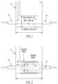
Figure 1 shows a flowmeter of the present invention. -
Figure 2 shows an acoustic signal path. -
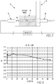
Figure 3 shows the low flow meter arrangement of the invention. -
Figure 4 shows a demonstration of transit time flow meter performance - a 4.5 mm diameter tube with 100 cSt Oil (3 Mhz Signal). - Referring now to the drawings wherein like reference numerals refer to similar or identical parts throughout the several views, and more specifically to
figures 1 and3 thereof, there is shown aflowmeter 10 for detecting fluid flow rates in apipe 12. Theflowmeter 10 comprises atube 14 having a channel disposed in thepipe 12 through which fluid in thepipe 12 flows. Theflowmeter 10 comprises an upstream ultrasonic transducer in contact with thepipe 12 and positioned in alignment with the channel so plane waves generated by theupstream transducer 16 propagate through the channel. Theflowmeter 10 comprises a downstream ultrasonic transducer in contact with thepipe 12 and positioned so plane waves generated by thedownstream transducer 18 propagate through the channel and are received by theupstream transducer 16 which produces anupstream transducer 16 signal. Thedownstream transducer 18 receives the plane waves from theupstream transducer 16 and provides adownstream transducer 18 signal. Theflowmeter 10 comprises acontroller 20 in communication with the upstream anddownstream transducers 18 which calculate fluid flow rate from theupstream transducer 16 signal and thedownstream transducer 18 signal. - The
tube 14 is made of a sound absorbing material so that essentially all non-fluid paths of sound are absorbed. Theupstream transducer 16 and thedownstream transducer 18 extend through thepipe 12 wall and acoustically communicate with thepipe 12 interior. Thetube 14 forms a seal with thepipe 12 essentially preventing fluid in thepipe 12 leaking around thetube 14. - The
tube 14 is made of a polymer filled with attenuative particles. The polymer may be either an epoxy, nylon, PTFE or PEEK (polyaryletheretherketone). The particles are either metal, glass microspheres, metal oxide or rubber having a size equal to or smaller than the acoustic wavelength. The tube may have a length L and a diameter opening D such that under volume flow conditions where Q > .2 liters/hour, the tube dimensions L/ D2 are greater than 1385/meters when C > 1400 m/s. - The present invention pertains to a method for detecting fluid flow rates in a
pipe 12. The method comprises the steps of flowing fluid through a channel of atube 14 disposed in thepipe 12. There is the step of generating plane waves by anupstream transducer 16 in contact with thepipe 12 and positioned in alignment with the channel so the plane waves propagate through the channel and are received by adownstream transducer 18 which produces adownstream transducer 18 signal. There is the step of generating plane waves by thedownstream transducer 18 in contact with thepipe 12 and positioned so the plane waves propagate through the channel and are received by theupstream transducer 16 which produces anupstream transducer 16 signal. There is the step of calculating with acontroller 20 in communication with the upstream anddownstream transducers 18 fluid flow rate from theupstream transducer 16 signal and thedownstream transducer 18 signal. - The
tube 14 is made of a sound absorbing material and wherein the generating plane waves by theupstream transducer 16 step includes the step of generating the plane waves by theupstream transducer 16 so that essentially all non-fluid paths of sound are absorbed by thetube 14, and wherein the generating plane waves by thedownstream transducer 18 step includes the step of generating the plane waves by thedownstream transducer 18 so that essentially all non-fluid paths of sound are absorbed by thetube 14. The generating plane waves by theupstream transducer 16 step includes the step of generating the plane waves by theupstream transducer 16 which extends through thepipe 12 wall and acoustically communicates with thepipe 12 interior, and wherein the generating plane waves by thedownstream transducer 18 step includes the step of generating the plane waves by thedownstream transducer 18 which extends through thepipe 12 wall and acoustically communicates with thepipe 12 interior. Thetube 14 forms a seal with thepipe 12 essentially preventing fluid in thepipe 12 leaking around thetube 14. - In the operation of the invention, the current ultrasonic flow meter arrangement uses two wetted transducers at opposing ends of a
tube 14 in apipe 12 where one is upstream from the fluid flow and other is downstream from the fluid flow, both transducers transmit and receive signals (Figure 1 ). The difference in transit times between the upstream and downstream signal is used to calculate the flow rate. Each transducer generates plane waves into the fluid and surroundingpipe 12 wall (Figure 2 ). The propagation of the sound wave has a profile known as the transducer beam profile. - For

- L: path length
- C: speed of sound in fluid
- V: fluid velocity
- Δt: t2 - t1 transit time difference
- Q: mass flow
- D: diameter of opening
- As the mass flow decreases so does the transit time difference between the upstream and downstream flow. By increasing the length "L" of the
tube 14 and decreasing the diameter opening "D" the effective Δt can be increased such that Δt > 1ns, under low mass flow conditions theflowmeter 10 has to be designed such that thetube 14 dimensions
- For
figure 1 :
- t1: upstream transit time
- t2: downstream transit time
- L: path length
- C: speed of sound in fluid
- V: fluid velocity
- Q=V·Area Q: Mass Flow D: diameter of opening

- In order to solve for the speed of sound in fluid and fluid velocity the upstream and downstream transit times need to be measured via a
controller 20. Thecontroller 20 computes the transit time differences between the upstream and downstream flow. The Δt is then used to calculate the fluid velocity for a givenflowmeter 10 length "L" for a calculated speed of sound "C". Once the velocity "V" has been calculated then the Mass Flow Q can be determined since the area "A" of the fluid opening orpipe 12 is known. - For
figure 2 : - λ: wavelength
- Nd: focal length

- r: radius of the transducer
- Since sound travels faster in the
solid pipe 12 ortube 14 wall than in the fluid medium, the receiving transducer suffers from acoustic noise from thepipe 12/tube 14 acoustic paths. This acoustic noise arrives at a time preceding the sound that travels in the liquid since sound velocities in the solid are higher than those in the fluid. This noise is significant because it reduces the accuracy of the flow measurement and results in a poor or no measurement at low flow rates. The measure of the affect of this noise is signal to noise ratio. - In order to solve this problem, a
tube 14 with acoustically attenuative properties is in inserted within the pipe 12 (Figure 3 ). Theacoustic tube 14 has a small inner diameter and a large outer diameter. The opening in thetube 14 acts as conduit for the fluid and the fluid path for sound, while the surrounding area acts as sound absorber. After the sound travels through the conduit it begins to spread again but this has no effect on the signal to noise ratio therefore the surrounding sound absorber successfully disables thepipe 12 noise. - The
tube 14 is made of a polymer filled with attenuative particles, for example tungsten particles (mesh 200) with a certain volume fraction up to 50%. The polymer can be for example epoxy, nylon, PTFE or PEEK but is not limited to these materials. The choice of polymer is dependent on the pressure rating of the application and its effectiveness in working with the attenuative particles to attenuate sound. The filler can be any metal, metal oxide, or rubber with a small mesh size, the lower the volume fraction of particle filler the higher the acoustic attenuation. Once a cylinder is fabricated then it is machined such that there is an inner diameter for fluid flow. Thesound absorbing tube 14 can be threaded on the OD; therefore, it screws into theflowmeter 10. Thesound absorbing tube 14 can be glued on the OD; therefore, it bonds into theflowmeter 10. Thesound absorbing tube 14 can either press fit or captured by clips or retainers. - Simple ultrasonic flow measurement tests have shown an improvement in the signal to noise ratio at low flow rates. The experimental setup included 5 MHz frequency ultrasonic transducers separated a distance of 4 inches. The
tube 14 used had an inner diameter of ¼" and outer diameter of 1". Thetube 14 was made of epoxy with tungsten particle filler. For test purposes olive oil was used since it has a similar viscosity to certain injection chemicals to be applied. It is noted that the higher the viscosity of the fluid, the more important the sound absorbing properties become. Specifically, as the viscosity increases, the fluid path acoustic signal is attenuated and the signal to noise ratio decreases. - A flow rate of 1 liter/hour was measured and the signal to noise ratio improved by 10 times using the
attenuative tube 14. Flow rates as low as 0.2 Liters/hour are readily achievable. Flow rates up to 90 liters/hour may also be analyzed. The low flow meter enables a chemical injection metering valve to dispense corrosion preventing chemicals to the subsea well at a low flow rate. The low flow meter is being used for chemical injection, but it could also be used for any application requiring a measurement at low flow rates. Seefigure 4 which shows a demonstration of transit time flow meter performance - a 4.5 mm diameter tube with 100 cSt Oil (3 MHz Signal). - During ultrasound transmission any sound which propagates at an angle after the transducer focal length is attenuated or absorbed within the
sound absorber tube 14 walls. This allows a line of sight ultrasound signal to be received uninhibited from any other acoustic noise source. As a result the signal to noise ratio is greatly improved thereby enabling ultrasonic transit time flow measurements at very low flow rates that were not possible before since the SNR increased 10 times fold. This invention will be used in a low flow meter for monitoring fluid injection in subsea oil wells.


f: frequency
Claims (8)
- A flowmeter (10) for detecting fluid flow rates in a pipe (12) comprising:a tube (14) having a channel disposed in the pipe (12) through which fluid in the pipe (12) flows, wherein the tube (14) is made of a sound absorbing material so that essentially all non-fluid paths of sound are absorbed and wherein the tube (14) forms a seal with the pipe (12) essentially preventing fluid in the pipe (12) leaking around the tube (14), the tube (14) being made of a polymer filled with attenuative particles;an upstream ultrasonic transducer (16) in contact with the pipe (12) and positioned in alignment with the channel so that plane waves generated by the upstream transducer (16) propagates through the channel;a downstream ultrasonic transducer (18) in contact with the pipe (12) and positioned in alignment with the channel so that plane waves generated by the downstream transducer (18) propagate through the channel and are received by the upstream transducer (16) which produces an upstream transducer signal, the downstream transducer (18) receiving the plane waves from the upstream transducer (18) and providing a downstream transducer signal;wherein the upstream transducer (16) and the downstream transducer (18) extend through the pipe wall and acoustically communicate with the pipe interior; anda controller (20) in communication with the upstream and downstream transducers (16. 18) which calculate fluid flow rate from the upstream transducer signal and the downstream transducer signal.
- The flowmeter as described in Claim 1, wherein the polymer is either an epoxy, nylon, PTFE or PEEK.
- The flowmeter as described in Claim 2, wherein the particles are either metal, metal oxide, glass microspheres or rubber having a mesh size less or equal to the acoustic wavelength.
- The flowmeter as described in any preceding Claim, wherein the tube (14) has a length L and a diameter opening D such that under volume flow conditions where Q > .2 liters/hour, the tube (14) dimensions L/D2 are greater than 1385/meters when C > 1400 m/s, where C is the speed of sound in the fluid.
- A method for detecting fluid flow rates in a pipe (12) comprising the steps of:flowing fluid through a channel of a tube (14) disposed in the pipe (12), wherein the tube (14) is made of a sound absorbing material so that essentially all non-fluid paths of sound are absorbed and wherein the tube (14) forms a seal with the pipe (12) essentially preventing fluid in the pipe (12) leaking around the tube (14), the tube (14) being made of a polymer filled with attenuative particles;generating plane waves by an upstream ultrasonic transducer (16) in contact with the pipe (12) and positioned in alignment with the channel so the plane waves propagate through the channel and are received by a downstream transducer (18) which produces a downstream transducer signal;generating plane waves by the downstream ultrasonic transducer (18) in contact with the pipe (12) and positioned in alignment with the channel so the plane waves propagate through the channel and are received by the upstream transducer (16) which produces an upstream transducer signal; andcalculating with a controller (20) in communication with the upstream and downstream transducers (16, 18) fluid flow rate from the upstream transducer signal and the downstream transducer signal.
- The method as described in Claim 5, wherein the tube is made of a sound absorbing material and wherein the generating plane waves by the upstream transducer step includes the step of generating the plane waves by the upstream transducer so that essentially all non-fluid paths of sound are absorbed by the tube, and wherein the generating plane waves by the downstream transducer step includes the step of generating the plane waves by the downstream transducer so that essentially all non-fluid paths of sound are absorbed by the tube.
- The method as described in Claim 6, wherein the generating plane waves by the upstream transducer step includes the step of generating the plane waves by the upstream transducer which extends through the pipe wall and acoustically communicates with the pipe interior, and wherein the generating plane waves by the downstream transducer step includes the step of generating the plane waves by the downstream transducer which extends through the pipe wall and acoustically communicates with the pipe interior.
- The method as described in any of Claims 5 to 7, wherein the tube has a length L and a diameter opening D such that under volume flow conditions where Q > .2 liters/hour, the tube dimensions L/D2 are greater than 1385/meters when C > 1400 m/s, where C is the speed of sound in the fluid.
Applications Claiming Priority (2)
| Application Number | Priority Date | Filing Date | Title |
|---|---|---|---|
| US12/653,087 US8245581B2 (en) | 2009-12-08 | 2009-12-08 | Flowmeter and method |
| PCT/US2010/055873 WO2011071633A1 (en) | 2009-12-08 | 2010-11-08 | Flowmeter and method |
Publications (2)
| Publication Number | Publication Date |
|---|---|
| EP2510317A1 EP2510317A1 (en) | 2012-10-17 |
| EP2510317B1 true EP2510317B1 (en) | 2020-10-21 |
Family
ID=43539831
Family Applications (1)
| Application Number | Title | Priority Date | Filing Date |
|---|---|---|---|
| EP10776916.8A Active EP2510317B1 (en) | 2009-12-08 | 2010-11-08 | Flowmeter and method |
Country Status (9)
| Country | Link |
|---|---|
| US (5) | US8245581B2 (en) |
| EP (1) | EP2510317B1 (en) |
| KR (1) | KR101730377B1 (en) |
| CN (1) | CN102667419B (en) |
| BR (1) | BR112012013584B1 (en) |
| CA (1) | CA2783085C (en) |
| DK (1) | DK2510317T3 (en) |
| MX (1) | MX2012006264A (en) |
| WO (1) | WO2011071633A1 (en) |
Families Citing this family (18)
| Publication number | Priority date | Publication date | Assignee | Title |
|---|---|---|---|---|
| EP2396273A2 (en) * | 2009-02-09 | 2011-12-21 | Warren Rogers Associates, Inc. | Method and apparatus for monitoring fluid storage and dispensing systems |
| US8245581B2 (en) * | 2009-12-08 | 2012-08-21 | Cameron International Corporation | Flowmeter and method |
| US8181536B2 (en) * | 2009-12-19 | 2012-05-22 | Cameron International Corporation | Ultrasonic Flow Meter including a transducer having conical face |
| US8726739B2 (en) | 2011-10-26 | 2014-05-20 | General Electric Company | Torsional sensor including a high-pressure sealing mechanism and system for measurement of fluid parameters |
| US9170140B2 (en) * | 2012-05-04 | 2015-10-27 | Cameron International Corporation | Ultrasonic flowmeter with internal surface coating and method |
| GB201312558D0 (en) | 2013-07-12 | 2013-08-28 | Gill Res And Dev Ltd | An ultrasonic flowmeter |
| US20150051864A1 (en) * | 2013-08-19 | 2015-02-19 | Andrei S. Dukhin | Device and Method for Determining Particle Size Distribution On-line Using Acoustic Spectroscopy Through a Pipe |
| US9365271B2 (en) * | 2013-09-10 | 2016-06-14 | Cameron International Corporation | Fluid injection system |
| US20160187172A1 (en) * | 2014-12-30 | 2016-06-30 | Cameron International Corporation | Ultrasonic viscometer |
| US9714855B2 (en) | 2015-01-26 | 2017-07-25 | Arad Ltd. | Ultrasonic water meter |
| US10281306B2 (en) | 2015-09-14 | 2019-05-07 | Cameron International Corporation | Flow meter system |
| CN106323393B (en) * | 2016-08-31 | 2018-12-18 | 电子科技大学 | A kind of double mode micro liquid flowmeter based on light manipulation |
| FR3065106B1 (en) | 2017-04-10 | 2019-08-02 | Efs Sa | METHOD FOR CONTROLLING AN ULTRASOUND MEASURING APPARATUS OF THE FLOW RATE IN A MEASUREMENT CHANNEL |
| FR3065070B1 (en) | 2017-04-10 | 2019-06-14 | Efs Sa | PARASITE WAVE MANAGEMENT STRUCTURE OF ULTRASOUND FLOWMETER |
| KR102214956B1 (en) * | 2019-09-02 | 2021-02-10 | 효성화학 주식회사 | Polyketone Water Meter |
| EP4217685B1 (en) * | 2020-09-23 | 2026-06-17 | Uhde High Pressure Technologies GmbH | High pressure installation, method for determining a flow control variable of a fluid flow flowing through a high-pressure outlet of a high-pressure pump, and use of an ultrasonic measuring device for determining a flow value of a fluid flow flowing through a thick-walled pipe of a high-pressure outlet of a high-pressure pump |
| US11860077B2 (en) * | 2021-12-14 | 2024-01-02 | Saudi Arabian Oil Company | Fluid flow sensor using driver and reference electromechanical resonators |
| US12281925B2 (en) * | 2022-05-31 | 2025-04-22 | Itron Global Sarl | Pressure sensor embedded in a metering device |
Family Cites Families (16)
| Publication number | Priority date | Publication date | Assignee | Title |
|---|---|---|---|---|
| US3245581A (en) * | 1964-07-06 | 1966-04-12 | Walter R Reach | Apparatus for vending heated comestible products |
| US3783967A (en) * | 1972-02-24 | 1974-01-08 | Us Health | Focusing protective enclosure for ultrasonic transducer |
| US4003252A (en) * | 1974-08-16 | 1977-01-18 | The Institutes Of Medical Sciences | Acoustical wave flowmeter |
| DE2648718C2 (en) * | 1976-10-27 | 1978-12-21 | Danfoss A/S, Nordborg (Daenemark) | Device that works with ultrasound to determine the physical quantities of a medium |
| US4398424A (en) * | 1980-12-16 | 1983-08-16 | Micro Pure Systems, Inc. | Ultrasonic sensing |
| DE3518266A1 (en) * | 1985-05-21 | 1986-11-27 | Siemens AG, 1000 Berlin und 8000 München | FLOWMETER |
| US6338277B1 (en) * | 1997-06-06 | 2002-01-15 | G. Kromschroder Aktiengesellschaft | Flowmeter for attenuating acoustic propagations |
| US6370963B1 (en) * | 2000-06-13 | 2002-04-16 | Murray F. Feller | Ultrasonic transit time flow sensor and method |
| EP1279368A3 (en) * | 2001-07-17 | 2004-09-15 | ndd Medizintechnik AG | Device for measuring the flow velocity and/or molecular mass of gases ou gasmixtures |
| US20040123666A1 (en) * | 2002-12-31 | 2004-07-01 | Ao Xiaolei S. | Ultrasonic damping material |
| CA2520563C (en) * | 2003-04-21 | 2013-03-12 | Teijin Pharma Limited | Ultrasonic apparatus and method for measuring the concentration and flow rate of gas |
| ES2358346T3 (en) * | 2005-08-11 | 2011-05-09 | 3M Innovative Properties Company | ITEMS COVERED THAT INCLUDE METAL SUBSTRATES. |
| US7546899B2 (en) * | 2005-10-05 | 2009-06-16 | Arrowhead Products Corporation | Lightweight polymer muffler apparatus and method of making same |
| US7410308B2 (en) * | 2006-01-09 | 2008-08-12 | All Optronics, Inc. | Fiber optic cable splice |
| DK2361371T3 (en) * | 2006-03-29 | 2018-01-22 | Mccrometer Inc | FLUID FLOW METER AND MIXTURES |
| US8245581B2 (en) * | 2009-12-08 | 2012-08-21 | Cameron International Corporation | Flowmeter and method |
-
2009
- 2009-12-08 US US12/653,087 patent/US8245581B2/en active Active
-
2010
- 2010-11-08 KR KR1020127017643A patent/KR101730377B1/en active Active
- 2010-11-08 CA CA2783085A patent/CA2783085C/en active Active
- 2010-11-08 EP EP10776916.8A patent/EP2510317B1/en active Active
- 2010-11-08 MX MX2012006264A patent/MX2012006264A/en active IP Right Grant
- 2010-11-08 WO PCT/US2010/055873 patent/WO2011071633A1/en not_active Ceased
- 2010-11-08 CN CN201080057816.8A patent/CN102667419B/en active Active
- 2010-11-08 BR BR112012013584A patent/BR112012013584B1/en active IP Right Grant
- 2010-11-08 DK DK10776916.8T patent/DK2510317T3/en active
-
2012
- 2012-08-02 US US13/565,341 patent/US8806734B2/en active Active
-
2014
- 2014-08-06 US US14/453,373 patent/US9389108B2/en active Active
-
2016
- 2016-06-29 US US15/196,998 patent/US9709427B2/en active Active
-
2017
- 2017-07-14 US US15/650,242 patent/US20170314976A1/en not_active Abandoned
Non-Patent Citations (1)
| Title |
|---|
| None * |
Also Published As
| Publication number | Publication date |
|---|---|
| CN102667419B (en) | 2016-03-09 |
| US20170314976A1 (en) | 2017-11-02 |
| MX2012006264A (en) | 2012-06-19 |
| US20140345390A1 (en) | 2014-11-27 |
| US8806734B2 (en) | 2014-08-19 |
| EP2510317A1 (en) | 2012-10-17 |
| DK2510317T3 (en) | 2021-01-25 |
| BR112012013584B1 (en) | 2020-06-09 |
| US20120297620A1 (en) | 2012-11-29 |
| CN102667419A (en) | 2012-09-12 |
| US8245581B2 (en) | 2012-08-21 |
| US20160305804A1 (en) | 2016-10-20 |
| US9389108B2 (en) | 2016-07-12 |
| CA2783085C (en) | 2020-06-02 |
| WO2011071633A1 (en) | 2011-06-16 |
| US20110132103A1 (en) | 2011-06-09 |
| BR112012013584A2 (en) | 2016-07-05 |
| CA2783085A1 (en) | 2011-06-16 |
| KR101730377B1 (en) | 2017-04-26 |
| KR20120098870A (en) | 2012-09-05 |
| US9709427B2 (en) | 2017-07-18 |
Similar Documents
| Publication | Publication Date | Title |
|---|---|---|
| US9709427B2 (en) | Flowmeter and method | |
| US6575043B1 (en) | Method and apparatus for characterizing flows based on attenuation of in-wall propagating wave modes | |
| US7607358B2 (en) | Flow rate determination of a gas-liquid fluid mixture | |
| US11293791B2 (en) | Leaky lamb wave flowmeter | |
| EP2513611B1 (en) | Ultrasonic transducer, flow meter and method | |
| US20040123666A1 (en) | Ultrasonic damping material | |
| US9046399B2 (en) | Minimally intrusive monitoring of a multiphase process flow using a tracer and a spatially arranged array of at least two sensors on a flow pipe | |
| US10890471B2 (en) | Method and assembly for ultrasonic clamp-on flow measurement, and bodies for implementing off-center flow measurement | |
| JP3761399B2 (en) | Ultrasonic flow meter | |
| CN102829829A (en) | Method and device for detecting ultrasonic flow by time-difference method | |
| CN102829830A (en) | Method and device used for detecting spreading speed of ultrasonic waves in ultrasonic flow detection | |
| CN103270395A (en) | Ultrasonic flow meter | |
| Chun et al. | Assessment of combined V/Z clamp-on ultrasonic flow metering | |
| US20200209029A1 (en) | Circumferential Resonance Flowmeter | |
| Warmenhoven et al. | The Application of Clamp-On Ultrasonic Flowmeters in Production Monitoring | |
| HirayamaUU et al. | ACCURACY IMPROVEMENT ON NON-INVASIVE ULTRASONIC-DOPPLER FLOW MEASUREMENT BY UTILZING SHEAR WAVES IN METAL PIPE | |
| JP2005195374A (en) | Ultrasonic flow meter and wedge used therefor | |
| SA08290690B1 (en) | Multiphase Flow Measurement |
Legal Events
| Date | Code | Title | Description |
|---|---|---|---|
| PUAI | Public reference made under article 153(3) epc to a published international application that has entered the european phase |
Free format text: ORIGINAL CODE: 0009012 |
|
| 17P | Request for examination filed |
Effective date: 20120709 |
|
| AK | Designated contracting states |
Kind code of ref document: A1 Designated state(s): AL AT BE BG CH CY CZ DE DK EE ES FI FR GB GR HR HU IE IS IT LI LT LU LV MC MK MT NL NO PL PT RO RS SE SI SK SM TR |
|
| DAX | Request for extension of the european patent (deleted) | ||
| RAP1 | Party data changed (applicant data changed or rights of an application transferred) |
Owner name: CAMERON TECHNOLOGIES LIMITED |
|
| STAA | Information on the status of an ep patent application or granted ep patent |
Free format text: STATUS: EXAMINATION IS IN PROGRESS |
|
| 17Q | First examination report despatched |
Effective date: 20190320 |
|
| GRAP | Despatch of communication of intention to grant a patent |
Free format text: ORIGINAL CODE: EPIDOSNIGR1 |
|
| STAA | Information on the status of an ep patent application or granted ep patent |
Free format text: STATUS: GRANT OF PATENT IS INTENDED |
|
| INTG | Intention to grant announced |
Effective date: 20200514 |
|
| GRAS | Grant fee paid |
Free format text: ORIGINAL CODE: EPIDOSNIGR3 |
|
| GRAA | (expected) grant |
Free format text: ORIGINAL CODE: 0009210 |
|
| STAA | Information on the status of an ep patent application or granted ep patent |
Free format text: STATUS: THE PATENT HAS BEEN GRANTED |
|
| AK | Designated contracting states |
Kind code of ref document: B1 Designated state(s): AL AT BE BG CH CY CZ DE DK EE ES FI FR GB GR HR HU IE IS IT LI LT LU LV MC MK MT NL NO PL PT RO RS SE SI SK SM TR |
|
| REG | Reference to a national code |
Ref country code: GB Ref legal event code: FG4D |
|
| REG | Reference to a national code |
Ref country code: CH Ref legal event code: EP |
|
| REG | Reference to a national code |
Ref country code: DE Ref legal event code: R096 Ref document number: 602010065727 Country of ref document: DE |
|
| REG | Reference to a national code |
Ref country code: IE Ref legal event code: FG4D |
|
| REG | Reference to a national code |
Ref country code: AT Ref legal event code: REF Ref document number: 1326279 Country of ref document: AT Kind code of ref document: T Effective date: 20201115 |
|
| REG | Reference to a national code |
Ref country code: DK Ref legal event code: T3 Effective date: 20210122 |
|
| REG | Reference to a national code |
Ref country code: NL Ref legal event code: FP |
|
| REG | Reference to a national code |
Ref country code: AT Ref legal event code: MK05 Ref document number: 1326279 Country of ref document: AT Kind code of ref document: T Effective date: 20201021 |
|
| REG | Reference to a national code |
Ref country code: NO Ref legal event code: T2 Effective date: 20201021 |
|
| PG25 | Lapsed in a contracting state [announced via postgrant information from national office to epo] |
Ref country code: GR Free format text: LAPSE BECAUSE OF FAILURE TO SUBMIT A TRANSLATION OF THE DESCRIPTION OR TO PAY THE FEE WITHIN THE PRESCRIBED TIME-LIMIT Effective date: 20210122 Ref country code: PT Free format text: LAPSE BECAUSE OF FAILURE TO SUBMIT A TRANSLATION OF THE DESCRIPTION OR TO PAY THE FEE WITHIN THE PRESCRIBED TIME-LIMIT Effective date: 20210222 Ref country code: FI Free format text: LAPSE BECAUSE OF FAILURE TO SUBMIT A TRANSLATION OF THE DESCRIPTION OR TO PAY THE FEE WITHIN THE PRESCRIBED TIME-LIMIT Effective date: 20201021 Ref country code: RS Free format text: LAPSE BECAUSE OF FAILURE TO SUBMIT A TRANSLATION OF THE DESCRIPTION OR TO PAY THE FEE WITHIN THE PRESCRIBED TIME-LIMIT Effective date: 20201021 |
|
| REG | Reference to a national code |
Ref country code: LT Ref legal event code: MG4D |
|
| PG25 | Lapsed in a contracting state [announced via postgrant information from national office to epo] |
Ref country code: LV Free format text: LAPSE BECAUSE OF FAILURE TO SUBMIT A TRANSLATION OF THE DESCRIPTION OR TO PAY THE FEE WITHIN THE PRESCRIBED TIME-LIMIT Effective date: 20201021 Ref country code: PL Free format text: LAPSE BECAUSE OF FAILURE TO SUBMIT A TRANSLATION OF THE DESCRIPTION OR TO PAY THE FEE WITHIN THE PRESCRIBED TIME-LIMIT Effective date: 20201021 Ref country code: SE Free format text: LAPSE BECAUSE OF FAILURE TO SUBMIT A TRANSLATION OF THE DESCRIPTION OR TO PAY THE FEE WITHIN THE PRESCRIBED TIME-LIMIT Effective date: 20201021 Ref country code: IS Free format text: LAPSE BECAUSE OF FAILURE TO SUBMIT A TRANSLATION OF THE DESCRIPTION OR TO PAY THE FEE WITHIN THE PRESCRIBED TIME-LIMIT Effective date: 20210221 Ref country code: ES Free format text: LAPSE BECAUSE OF FAILURE TO SUBMIT A TRANSLATION OF THE DESCRIPTION OR TO PAY THE FEE WITHIN THE PRESCRIBED TIME-LIMIT Effective date: 20201021 Ref country code: AT Free format text: LAPSE BECAUSE OF FAILURE TO SUBMIT A TRANSLATION OF THE DESCRIPTION OR TO PAY THE FEE WITHIN THE PRESCRIBED TIME-LIMIT Effective date: 20201021 Ref country code: BG Free format text: LAPSE BECAUSE OF FAILURE TO SUBMIT A TRANSLATION OF THE DESCRIPTION OR TO PAY THE FEE WITHIN THE PRESCRIBED TIME-LIMIT Effective date: 20210121 |
|
| REG | Reference to a national code |
Ref country code: DE Ref legal event code: R119 Ref document number: 602010065727 Country of ref document: DE |
|
| PG25 | Lapsed in a contracting state [announced via postgrant information from national office to epo] |
Ref country code: HR Free format text: LAPSE BECAUSE OF FAILURE TO SUBMIT A TRANSLATION OF THE DESCRIPTION OR TO PAY THE FEE WITHIN THE PRESCRIBED TIME-LIMIT Effective date: 20201021 |
|
| REG | Reference to a national code |
Ref country code: CH Ref legal event code: PL |
|
| PG25 | Lapsed in a contracting state [announced via postgrant information from national office to epo] |
Ref country code: LT Free format text: LAPSE BECAUSE OF FAILURE TO SUBMIT A TRANSLATION OF THE DESCRIPTION OR TO PAY THE FEE WITHIN THE PRESCRIBED TIME-LIMIT Effective date: 20201021 Ref country code: LU Free format text: LAPSE BECAUSE OF NON-PAYMENT OF DUE FEES Effective date: 20201108 Ref country code: MC Free format text: LAPSE BECAUSE OF FAILURE TO SUBMIT A TRANSLATION OF THE DESCRIPTION OR TO PAY THE FEE WITHIN THE PRESCRIBED TIME-LIMIT Effective date: 20201021 Ref country code: SK Free format text: LAPSE BECAUSE OF FAILURE TO SUBMIT A TRANSLATION OF THE DESCRIPTION OR TO PAY THE FEE WITHIN THE PRESCRIBED TIME-LIMIT Effective date: 20201021 Ref country code: RO Free format text: LAPSE BECAUSE OF FAILURE TO SUBMIT A TRANSLATION OF THE DESCRIPTION OR TO PAY THE FEE WITHIN THE PRESCRIBED TIME-LIMIT Effective date: 20201021 Ref country code: SM Free format text: LAPSE BECAUSE OF FAILURE TO SUBMIT A TRANSLATION OF THE DESCRIPTION OR TO PAY THE FEE WITHIN THE PRESCRIBED TIME-LIMIT Effective date: 20201021 Ref country code: EE Free format text: LAPSE BECAUSE OF FAILURE TO SUBMIT A TRANSLATION OF THE DESCRIPTION OR TO PAY THE FEE WITHIN THE PRESCRIBED TIME-LIMIT Effective date: 20201021 Ref country code: CZ Free format text: LAPSE BECAUSE OF FAILURE TO SUBMIT A TRANSLATION OF THE DESCRIPTION OR TO PAY THE FEE WITHIN THE PRESCRIBED TIME-LIMIT Effective date: 20201021 |
|
| REG | Reference to a national code |
Ref country code: BE Ref legal event code: MM Effective date: 20201130 |
|
| PLBE | No opposition filed within time limit |
Free format text: ORIGINAL CODE: 0009261 |
|
| STAA | Information on the status of an ep patent application or granted ep patent |
Free format text: STATUS: NO OPPOSITION FILED WITHIN TIME LIMIT |
|
| PG25 | Lapsed in a contracting state [announced via postgrant information from national office to epo] |
Ref country code: LI Free format text: LAPSE BECAUSE OF NON-PAYMENT OF DUE FEES Effective date: 20201130 Ref country code: CH Free format text: LAPSE BECAUSE OF NON-PAYMENT OF DUE FEES Effective date: 20201130 |
|
| 26N | No opposition filed |
Effective date: 20210722 |
|
| PG25 | Lapsed in a contracting state [announced via postgrant information from national office to epo] |
Ref country code: FR Free format text: LAPSE BECAUSE OF NON-PAYMENT OF DUE FEES Effective date: 20201221 Ref country code: AL Free format text: LAPSE BECAUSE OF FAILURE TO SUBMIT A TRANSLATION OF THE DESCRIPTION OR TO PAY THE FEE WITHIN THE PRESCRIBED TIME-LIMIT Effective date: 20201021 Ref country code: IE Free format text: LAPSE BECAUSE OF NON-PAYMENT OF DUE FEES Effective date: 20201108 |
|
| PG25 | Lapsed in a contracting state [announced via postgrant information from national office to epo] |
Ref country code: SI Free format text: LAPSE BECAUSE OF FAILURE TO SUBMIT A TRANSLATION OF THE DESCRIPTION OR TO PAY THE FEE WITHIN THE PRESCRIBED TIME-LIMIT Effective date: 20201021 Ref country code: DE Free format text: LAPSE BECAUSE OF NON-PAYMENT OF DUE FEES Effective date: 20210601 |
|
| PG25 | Lapsed in a contracting state [announced via postgrant information from national office to epo] |
Ref country code: IS Free format text: LAPSE BECAUSE OF FAILURE TO SUBMIT A TRANSLATION OF THE DESCRIPTION OR TO PAY THE FEE WITHIN THE PRESCRIBED TIME-LIMIT Effective date: 20210221 Ref country code: TR Free format text: LAPSE BECAUSE OF FAILURE TO SUBMIT A TRANSLATION OF THE DESCRIPTION OR TO PAY THE FEE WITHIN THE PRESCRIBED TIME-LIMIT Effective date: 20201021 Ref country code: MT Free format text: LAPSE BECAUSE OF FAILURE TO SUBMIT A TRANSLATION OF THE DESCRIPTION OR TO PAY THE FEE WITHIN THE PRESCRIBED TIME-LIMIT Effective date: 20201021 Ref country code: CY Free format text: LAPSE BECAUSE OF FAILURE TO SUBMIT A TRANSLATION OF THE DESCRIPTION OR TO PAY THE FEE WITHIN THE PRESCRIBED TIME-LIMIT Effective date: 20201021 |
|
| PG25 | Lapsed in a contracting state [announced via postgrant information from national office to epo] |
Ref country code: MK Free format text: LAPSE BECAUSE OF FAILURE TO SUBMIT A TRANSLATION OF THE DESCRIPTION OR TO PAY THE FEE WITHIN THE PRESCRIBED TIME-LIMIT Effective date: 20201021 |
|
| PG25 | Lapsed in a contracting state [announced via postgrant information from national office to epo] |
Ref country code: BE Free format text: LAPSE BECAUSE OF NON-PAYMENT OF DUE FEES Effective date: 20201130 |
|
| P01 | Opt-out of the competence of the unified patent court (upc) registered |
Effective date: 20231208 |
|
| PGFP | Annual fee paid to national office [announced via postgrant information from national office to epo] |
Ref country code: NL Payment date: 20250912 Year of fee payment: 16 |
|
| PGFP | Annual fee paid to national office [announced via postgrant information from national office to epo] |
Ref country code: GB Payment date: 20250918 Year of fee payment: 16 |
|
| PGFP | Annual fee paid to national office [announced via postgrant information from national office to epo] |
Ref country code: NO Payment date: 20251113 Year of fee payment: 16 |
|
| PGFP | Annual fee paid to national office [announced via postgrant information from national office to epo] |
Ref country code: DK Payment date: 20251112 Year of fee payment: 16 Ref country code: IT Payment date: 20251022 Year of fee payment: 16 |