EP2509395A2 - Solid-State Light Emitting Device Having Controllable Multiphase Reactive Power - Google Patents
Solid-State Light Emitting Device Having Controllable Multiphase Reactive Power Download PDFInfo
- Publication number
- EP2509395A2 EP2509395A2 EP12163398A EP12163398A EP2509395A2 EP 2509395 A2 EP2509395 A2 EP 2509395A2 EP 12163398 A EP12163398 A EP 12163398A EP 12163398 A EP12163398 A EP 12163398A EP 2509395 A2 EP2509395 A2 EP 2509395A2
- Authority
- EP
- European Patent Office
- Prior art keywords
- solid
- light emitting
- phase
- state light
- power
- Prior art date
- Legal status (The legal status is an assumption and is not a legal conclusion. Google has not performed a legal analysis and makes no representation as to the accuracy of the status listed.)
- Ceased
Links
- 238000005286 illumination Methods 0.000 claims abstract description 32
- 230000001276 controlling effect Effects 0.000 claims description 104
- 230000005669 field effect Effects 0.000 claims description 30
- 230000001105 regulatory effect Effects 0.000 claims description 28
- 238000001514 detection method Methods 0.000 claims description 20
- 239000004065 semiconductor Substances 0.000 claims description 20
- 230000007935 neutral effect Effects 0.000 claims description 12
- XUIMIQQOPSSXEZ-UHFFFAOYSA-N Silicon Chemical compound [Si] XUIMIQQOPSSXEZ-UHFFFAOYSA-N 0.000 claims description 10
- 239000003990 capacitor Substances 0.000 claims description 10
- 230000003247 decreasing effect Effects 0.000 claims description 10
- 230000000694 effects Effects 0.000 claims description 10
- 230000006698 induction Effects 0.000 claims description 10
- 229910044991 metal oxide Inorganic materials 0.000 claims description 10
- 150000004706 metal oxides Chemical class 0.000 claims description 10
- 229910052710 silicon Inorganic materials 0.000 claims description 10
- 239000010703 silicon Substances 0.000 claims description 10
- 230000000087 stabilizing effect Effects 0.000 claims description 10
- 230000003287 optical effect Effects 0.000 claims description 5
- 230000033228 biological regulation Effects 0.000 claims description 4
- 239000007787 solid Substances 0.000 description 9
- 238000010586 diagram Methods 0.000 description 5
Images


Classifications
-
- H—ELECTRICITY
- H05—ELECTRIC TECHNIQUES NOT OTHERWISE PROVIDED FOR
- H05B—ELECTRIC HEATING; ELECTRIC LIGHT SOURCES NOT OTHERWISE PROVIDED FOR; CIRCUIT ARRANGEMENTS FOR ELECTRIC LIGHT SOURCES, IN GENERAL
- H05B45/00—Circuit arrangements for operating light-emitting diodes [LED]
- H05B45/30—Driver circuits
- H05B45/37—Converter circuits
- H05B45/3725—Switched mode power supply [SMPS]
-
- Y—GENERAL TAGGING OF NEW TECHNOLOGICAL DEVELOPMENTS; GENERAL TAGGING OF CROSS-SECTIONAL TECHNOLOGIES SPANNING OVER SEVERAL SECTIONS OF THE IPC; TECHNICAL SUBJECTS COVERED BY FORMER USPC CROSS-REFERENCE ART COLLECTIONS [XRACs] AND DIGESTS
- Y02—TECHNOLOGIES OR APPLICATIONS FOR MITIGATION OR ADAPTATION AGAINST CLIMATE CHANGE
- Y02B—CLIMATE CHANGE MITIGATION TECHNOLOGIES RELATED TO BUILDINGS, e.g. HOUSING, HOUSE APPLIANCES OR RELATED END-USER APPLICATIONS
- Y02B20/00—Energy efficient lighting technologies, e.g. halogen lamps or gas discharge lamps
- Y02B20/30—Semiconductor lamps, e.g. solid state lamps [SSL] light emitting diodes [LED] or organic LED [OLED]
-
- Y—GENERAL TAGGING OF NEW TECHNOLOGICAL DEVELOPMENTS; GENERAL TAGGING OF CROSS-SECTIONAL TECHNOLOGIES SPANNING OVER SEVERAL SECTIONS OF THE IPC; TECHNICAL SUBJECTS COVERED BY FORMER USPC CROSS-REFERENCE ART COLLECTIONS [XRACs] AND DIGESTS
- Y02—TECHNOLOGIES OR APPLICATIONS FOR MITIGATION OR ADAPTATION AGAINST CLIMATE CHANGE
- Y02B—CLIMATE CHANGE MITIGATION TECHNOLOGIES RELATED TO BUILDINGS, e.g. HOUSING, HOUSE APPLIANCES OR RELATED END-USER APPLICATIONS
- Y02B20/00—Energy efficient lighting technologies, e.g. halogen lamps or gas discharge lamps
- Y02B20/40—Control techniques providing energy savings, e.g. smart controller or presence detection
Definitions
- the present invention utilizes a three-phase or multiphase AC power source, and the electric power of each phase respectively drives its corresponding solid-state light emitting member, and the solid-state light emitting members respectively driven by each phase power are arranged adjacently or arranged with an overlapping means, so that the light of the individual solid-state tight emitting members respectively driven by the multiphase power source and arranged adjacently or arranged with an overlapping means can reduce the brightness pulse through synthetic illumination; and through being controlled by a solid-state switch device for controlling AC conductivity phase angle (1000) installed on the power source of each phase, when the illumination brightness of corresponding solid-state light emitting member is lower than that of other solid-state light emitting members arranged adjacently or arranged with an overlapping means, the power source is cut for saving energy.
- AC conductivity phase angle 1000
- One primary disadvantage of the conventional single phase AC power lamp is that the illumination brightness of the driven solid-state light emitting member is in a pulse state due to the voltage pulse of the AC power source; and in a multiphase AC power source, each phase power respectively drives individual solid-state light emitting member, because each phase power belongs to different phase, the peak values of different phase voltages are different at the same temporary time period, thereby the individual solid-state light emitting members respectively driven by each phase power generate the optical energy with different brightness for achieving a synthetic illumination, so the brightness pulse is reduced, wherein the driving power of the solid-state light emitting member with lower brightness would be formed as reactive power.
- the present invention utilizes a three-phase or multiphase AC power source, and each phase power respectively drives individual solid-state light emitting members arranged adjacently or arranged with an overlapping means, so that the synthetic illumination brightness is overlapped through the illumination brightness waveforms generated by the AC power voltage of each phase, thereby the synthetic pulse rate of illumination brightness can be lowered, and the sine waveform voltages at different phases between each power source enable the individual solid-state light emitting members respectively driven by each phase power and arranged adjacently or arranged with an overlapping means generate the optical energy having different brightness with respect to the instant value of the voltage waveform.
- the solid-state light emitting device having controllable multiphase reactive power utilizes a solid-state switch device for controlling AC conductivity phase angle (1000) for controlling the reactive power to be cut so as to save power, and to further regulate the current and voltage supplied to the individual solid-state light emitting member.
- One primary disadvantage of the conventional single phase AC power lamp is that the illumination brightness of the driven solid-state light emitting member is in a pulse state due to the voltage pulse of the AC power source; and in a multiphase AC power source, each phase power respectively drives individual solid-state light emitting member, because each phase power belongs to different phase, the peak values of different phase voltages are different at the same temporary time period, thereby the individual solid-state light emitting members respectively driven by each phase power generate the optical energy with different brightness for achieving a synthetic illumination, so the brightness pulse is reduced, wherein the driving power of the solid-state light emitting member with lower brightness would be formed as reactive power;
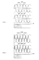
- FIG 1 is a synthetic illumination pulse waveform and current waveform showing utilizing a three-phase AC power source and each phase power respectively driving individual solid-state light emitting members arranged adjacently or arranged with an overlapping means.
- the present invention utilizes a three-phase or multiphase AC power source, and each phase power respectively drives individual solid-state light emitting members arranged adjacently or arranged with an overlapping means, so that the synthetic illumination brightness is overlapped through the illumination brightness waveforms generated by the AC power voltage of each phase, thereby synthetic pulse rate of illumination brightness can be lowered, and the sine waveform voltage at different phase between each power source enables the individual solid-state light emitting members respectively driven by each phase power and arranged adjacently or arranged with an overlapping means generate the optical energy having different brightness with respect to the instant value of the voltage waveform.
- the solid-state light emitting device having controllable multiphase reactive power utilizes a solid-state switch device for controlling AC conductivity phase angle (1000) for controlling the reactive power to be cut so as to save power, and to further regulate the current and voltage supplied to the individual solid-state light emitting member.
- the solid-state light emitting device having controllable multiphase reactive power adopts a three-phase AC power source, and the electric power of each phase respectively drives individual solid-state light emitting members arranged adjacently or arranged with an overlapping means for synthetic illumination, so that the pulse of illumination brightness is reduced, and a solid-state switch device for controlling AC conductivity phase angle (1000) is connected in series with each phase for saving reactive power, and the current and voltage supplied to the individual solid-state light emitting member can be further regulated;
- FIG 2 is a synthetic illumination pulse waveform and current waveform showing utilizing the three-phase AC power source and each phase power being regulated by the solid-state switch device for controlling AC conductivity phase angle (1000) then respectively driving individual solid-state light emitting members arranged adjacently or arranged with an overlapping means.
- the AC-power driven solid-state light emitting member (102) is connected in series with the AC current limiting circuit device (Z10) and connected in series with the solid-state switch device for controlling AC conductivity phase angle (1000), then connected in parallel between the three-phase AC power wire (S) and the three-phase AC power wire (T);
- the AC-power driven solid-state light emitting member (103) is connected in series with the AC current limiting circuit device (Z10) and connected in series with the solid-state switch device for controlling AC conductivity phase angle (1000), then connected in parallel between the three-phase AC power wire (T) and the three-phase AC power wire (R);
- the illumination waveform and current waveform diagrams obtained during the operation disclosed in the embodiment illustrated in FIG. 3 are the same as what is disclosed in FIG 2 .
- FIG. 4 is a circuit schematic view of utilizing the three-phase AC power source and each phase power being regulated by the solid-state switch device for controlling AC conductivity phase angle (1000) then respectively driving individual solid-state light emitting members connected in an Wye (Y) format and arranged adjacently or arranged with an overlapping means; as shown in FIG 4 , it mainly consists of:
- the non-common connection end of the AC-power driven solid-state light emitting member (101) is connected in series with the AC current limiting circuit device (Z10) and connected in series with the solid-state switch device for controlling AC conductivity phase angle (1000), and after the series connection, one end thereof is connected to the three-phase AC power wire (R);
- the non-common connection end of the AC-power driven solid-state light emitting member (102) is connected in series with the AC current limiting circuit device (Z10) and connected in series with the solid-state switch device for controlling AC conductivity phase angle (1000), and after the series connection, one end thereof is connected to the three-phase AC power wire (S);
- the non-common connection end of the AC-power driven solid-state light emitting member (103) is connected in series with the AC current limiting circuit device (Z10) and connected in series with the solid-state switch device for controlling AC conductivity phase angle (1000), and after the series connection, one end thereof is connected to the three-phase AC power wire (T);
- the illumination waveform and current waveform diagrams obtained during the operation disclosed in the embodiment illustrated in FIG 4 are the same as what is disclosed in FIG 2 .
- FIG 5 is a circuit schematic view of utilizing a three-phase four-wire AC power source and each phase power being regulated by the solid-state switch device for controlling AC conductivity phase angle (1000) then respectively driving individual solid-state light emitting members connected in an Wye (Y) format and arranged adjacently or arranged with an overlapping means; as shown in FIG 5 , mainly consists of:
- the non-common connection end of the AC-power driven solid-state light emitting member (101) is connected in series with the AC current limiting circuit device (Z 10) and connected in series with the solid-state switch device for controlling AC conductivity phase angle (1000), and after the series connection, one end thereof is connected to the three-phase four-wire AC power wire (R);
- the non-common connection end of the AC-power driven solid-state light emitting member (102) is connected in series with the AC current limiting circuit device (Z10) and connected in series with the solid-state switch device for controlling AC conductivity phase angle (1000), and after the series connection, one end thereof is connected to the three-phase four-wire AC power wire (S);
- the non-common connection end of the AC-power driven solid-state light emitting member (103) is connected in series with the AC current limiting circuit device (Z10) and connected in series with the solid-state switch device for controlling AC conductivity phase angle (1000), and after the series connection, one end thereof is connected to the three-phase four-wire AC power wire (T);
- the illumination waveform and current waveform diagrams obtained during the operation disclosed in the embodiment illustrated in FIG 5 are the same as what is disclosed in FIG. 2 .
- FIG 6 is the circuit schematic view in which each phase of the three-phase AC power source being individually connected in parallel with a circuit device in series connected by the AC current limiting circuit device (Z10), the AC solid-state light emitting member and the AC terminal of single-phase bridge rectifier (BR100), then the DC output terminal of the single-phase bridge rectifier (BR100) of each phase being homo-polar connected in parallel with the solid-state switch device for controlling electric conduction phase angle (2000), as shown in FIG 6 , it mainly consists of:
- the solid-state light emitting member (101) driven by AC power is in series connected to the AC current limiting circuit device (Z10) and in series connected to the AC terminal of single-phase bridge rectifier (BR100), then connected in parallel between the three-phase AC power wire (R) and the three-phase AC power wire (T);
- the solid-state light emitting member (102) driven by AC power is in series connected to the AC current limiting circuit device (Z10) and in series connected to the AC terminal of single-phase bridge rectifier (BR100), then connected in parallel between the three-phase AC power wire (S) and the three-phase AC power wire (R);
- the solid-state light emitting member (103) driven by AC power is in series connected to the AC current limiting circuit device (Z10) and in series connected to the AC terminal of single-phase bridge rectifier (BR100), then connected in parallel between the three-phase AC power wire (T) and the three-phase AC power wire (S);
- the illumination waveform and current waveform diagrams obtained during the operation disclosed in the embodiment illustrated in FIG 6 are the same as what is disclosed in FIG 2 .
- FIG 7 is the circuit schematic view in which a circuit device in series connected by the AC current limiting circuit device (Z10), the AC solid-state light emitting member and the AC terminal of single-phase bridge rectifier (BR100) being individually installed in parallel between each phase of R, S, and T of three-phase four-wire AC power source and the neutral wire of three-phase four-wire AC power source (N), then the DC output terminal of the single-phase bridge rectifier (BR100) of each phase being homo-polar connected in parallel with the solid-state switch device for controlling electric conduction phase angle (2000); as shown in FIG. 7 , it mainly consists of:
- the AC current limiting circuit device (Z10) is in series connected to the solid-state light emitting member (101), and in series connected to the AC terminal of single-phase bridge rectifier (BR100), then connected in parallel between the three-phase four-wire AC power wire (R) and the neutral wire of three-phase four-wire AC power source (N);
- the AC current limiting circuit device (Z10) is in series connected to the solid-state light emitting member (102), and in series connected to the AC terminal of single-phase bridge rectifier (BR100), then connected in parallel between the three-phase four-wire AC power wire (S) and the neutral wire of three-phase four-wire AC power source (N);
- the AC current limiting circuit device (Z10) is in series connected to the solid-state light emitting member (103), and in series connected to the AC terminal of single-phase bridge rectifier (BR100), then connected in parallel between the three-phase four-wire AC power wire (T) and the neutral wire of three-phase four-wire AC power source (N);
- the illumination waveform and current waveform diagrams obtained during the operation disclosed in the embodiment illustrated in FIG 7 are the same as what is disclosed in FIG. 2 .
- the AC solid-state light emitting members (101), (102), (103) are structured by light emitting diodes (LEDs) or organic light emitting diodes (OLEDs), including one or more than one of the following means:
- the AC solid-state light emitting members (101), (102), (103) are structured by single-way conductivity solid-state light emitting members, including one or more than one of the following means
- the AC solid-state light emitting members (101), (102), (103) are structured by one or more than one light emitting members in series connection, parallel connection or series and parallel connection, provided for being directly operated with an AC power source, so as to be directly operated with a AC power source.
- the mentioned multiplephase AC power source not only includes the three-phase power source adopted in aforesaid embodiments, the same theory and principle is also applicable in an AC power source having two or more than two phases.
Landscapes
- Circuit Arrangement For Electric Light Sources In General (AREA)
- Led Devices (AREA)
- Electroluminescent Light Sources (AREA)
Abstract
Description
- The present invention utilizes a three-phase or multiphase AC power source, and the electric power of each phase respectively drives its corresponding solid-state light emitting member, and the solid-state light emitting members respectively driven by each phase power are arranged adjacently or arranged with an overlapping means, so that the light of the individual solid-state tight emitting members respectively driven by the multiphase power source and arranged adjacently or arranged with an overlapping means can reduce the brightness pulse through synthetic illumination; and through being controlled by a solid-state switch device for controlling AC conductivity phase angle (1000) installed on the power source of each phase, when the illumination brightness of corresponding solid-state light emitting member is lower than that of other solid-state light emitting members arranged adjacently or arranged with an overlapping means, the power source is cut for saving energy.
- One primary disadvantage of the conventional single phase AC power lamp is that the illumination brightness of the driven solid-state light emitting member is in a pulse state due to the voltage pulse of the AC power source; and in a multiphase AC power source, each phase power respectively drives individual solid-state light emitting member, because each phase power belongs to different phase, the peak values of different phase voltages are different at the same temporary time period, thereby the individual solid-state light emitting members respectively driven by each phase power generate the optical energy with different brightness for achieving a synthetic illumination, so the brightness pulse is reduced, wherein the driving power of the solid-state light emitting member with lower brightness would be formed as reactive power.
- The present invention utilizes a three-phase or multiphase AC power source, and each phase power respectively drives individual solid-state light emitting members arranged adjacently or arranged with an overlapping means, so that the synthetic illumination brightness is overlapped through the illumination brightness waveforms generated by the AC power voltage of each phase, thereby the synthetic pulse rate of illumination brightness can be lowered, and the sine waveform voltages at different phases between each power source enable the individual solid-state light emitting members respectively driven by each phase power and arranged adjacently or arranged with an overlapping means generate the optical energy having different brightness with respect to the instant value of the voltage waveform. When the individual solid-state light emitting members having different brightness and arranged adjacently or arranged with an overlapping means emit light, the power passing through the individual solid-state light emitting member having a relatively low brightness is defined as reactive power. The solid-state light emitting device having controllable multiphase reactive power, provided by the present invention, utilizes a solid-state switch device for controlling AC conductivity phase angle (1000) for controlling the reactive power to be cut so as to save power, and to further regulate the current and voltage supplied to the individual solid-state light emitting member.
- According to another aspect of the present invention, a solid state light emitting device having controllable multiphase reactive power, which utilises a three phase or multiphase AC power source comprises a solid state light emitting member corresponding to each phase of the electric power; and a solid state switch device for controlling AC conductivity phase angle installed on the power source of each phase; wherein the solid state light emitting members are respectively driven by each phase power and are arranged adjacently or with an overlapping means, so that the light of the individual solid state light emitting members respectively driven by the multiphase power source and arranged adjacently or arranged with the overlapping means can reduce the brightness pulse through synthetic illumination; the solid state light emitting members being controlled by the solid state switch device so that, when the illumination brightness of corresponding solid state light emitting member is lower than that of other solid state light emitting members, the power source is cut. In this way, energy may be saved.
-
-
FIG. 1 is a synthetic illumination pulse waveform and current waveform showing utilizing a three-phase AC power source and each phase power respectively driving individual solid-state light emitting members arranged adjacently or arranged with an overlapping means. -
FIG. 2 is a synthetic illumination pulse waveform and current waveform showing utilizing the three-phase AC power source and each phase power being regulated by the solid-state switch device for controlling AC conductivity phase angle (1000) then respectively driving individual solid-state light emitting members arranged adjacently or arranged with an overlapping means. -
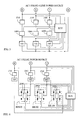
FIG 3 is a circuit schematic view of utilizing the three-phase AC power source and each phase power being regulated by the solid-state switch device for controlling AC conductivity phase angle (1000) then respectively driving individual solid-state light emitting members connected in a Delta (Δ) format and arranged adjacently or arranged with an overlapping means. -
FIG. 4 is a circuit schematic view of utilizing the three-phase AC power source and each phase power being regulated by the solid-state switch device for controlling AC conductivity phase angle (1000) then respectively driving individual solid-state light emitting members connected in an Wye (Y) format and arranged adjacently or arranged with an overlapping means. -
FIG. 5 is a circuit schematic view of utilizing a three-phase four-wire AC power source and each phase power being regulated by the solid-state switch device for controlling AC conductivity phase angle (1000) then respectively driving individual solid-state light emitting members connected in an Wye (Y) format and arranged adjacently or arranged with an overlapping means. -
FIG 6 is the circuit schematic view in which each phase of the three-phase AC power source being individually connected in parallel to a circuit device in series connected by the AC current limiting circuit device (Z10), the AC solid-state light emitting member and the AC terminal of single-phase bridge rectifier (BR100), then the DC output terminal of each phase of single-phase bridge rectifier (BR100) being homo-polar connected in parallel with the solid-state switch device for controlling electric conduction phase angle (2000). -
FIG 7 is the circuit schematic view in which a circuit device in series connected by the AC current limiting circuit device (Z10), the AC solid-state light emitting member and the AC terminal of single-phase bridge rectifier (BR100) being individually installed in parallel between each phase of R, S, and T of three-phase four-wire AC power source and the neutral wire of three-phase four-wire AC power source (N), then the DC output terminal of each phase of single-phase bridge rectifier (BR100) being homo-polar connected in parallel with the solid-state switch device for controlling electric conduction phase angle (2000). -
- (101) , (102) , (103) : Solid-state light emitting member
- (1000) : Solid-state switch device for controlling AC conductivity phase angle
- (2000) : Solid-state switch device for controlling electric conduction phase angle
- (BR100) : Single-phase bridge rectifier
- (Va) , (Vb) , (Vc) : Voltage waveform of the three-phase AC power source respectively driving individual solid-state light emitting members arranged adjacently or arranged with an overlapping means
- (Ia) , (Ib) , (Ic) : Current waveform of the three-phase AC power source respectively driving individual solid-state light emitting members arranged adjacently or arranged with an overlapping means
- (e) : Synthetic light waveform of the three-phase AC power source respectively driving individual solid-state light emitting members arranged adjacently or arranged with an overlapping means
- (Vda) , (Vdb) , (Vdc) : Voltage waveform of the three-phase AC power source being regulated by the solid-state switch device for controlling AC conductivity phase angle (1000) then respectively driving individual solid-state light emitting members arranged adjacently or arranged with an overlapping means
- (Ida) , (Idb) , (Idc) : Current waveform of the three-phase AC power source being regulated by the solid-state switch device for controlling AC conductivity phase angle (1000) then respectively driving individual solid-state light emitting members arranged adjacently or arranged with an overlapping means
- (de) : Synthetic light waveform of the three-phase AC power source being regulated by the solid-state switch device for controlling AC conductivity phase angle (1000) then respectively driving individual solid-state light emitting members arranged adjacently or arranged with an overlapping means
- (COM) : Common connection end
- (ECU) : Electric power control unit
- (N) : Neutral wire of three-phase four-wire AC power source
- (R) , (S) , (T) : Three-phase AC power wire
- (Z10) : AC current limiting circuit device
- One primary disadvantage of the conventional single phase AC power lamp is that the illumination brightness of the driven solid-state light emitting member is in a pulse state due to the voltage pulse of the AC power source; and in a multiphase AC power source, each phase power respectively drives individual solid-state light emitting member, because each phase power belongs to different phase, the peak values of different phase voltages are different at the same temporary time period, thereby the individual solid-state light emitting members respectively driven by each phase power generate the optical energy with different brightness for achieving a synthetic illumination, so the brightness pulse is reduced, wherein the driving power of the solid-state light emitting member with lower brightness would be formed as reactive power;
-
FIG 1 is a synthetic illumination pulse waveform and current waveform showing utilizing a three-phase AC power source and each phase power respectively driving individual solid-state light emitting members arranged adjacently or arranged with an overlapping means. - As shown in
FIG 1 , wherein: - (Va), (Vb) and (Vc) are voltage waveforms of the three-phase AC power source respectively driving individual solid-state light emitting members arranged adjacently or arranged with an overlapping means;
- (Ia), (Ib) and (Ic) are current waveforms of the three-phase AC power source respectively driving individual solid-state light emitting members arranged adjacently or arranged with an overlapping means;
- (e) is a synthetic illumination waveform of the three-phase AC power source respectively driving individual solid-state light emitting members arranged adjacently or arranged with an overlapping means;
- The present invention utilizes a three-phase or multiphase AC power source, and each phase power respectively drives individual solid-state light emitting members arranged adjacently or arranged with an overlapping means, so that the synthetic illumination brightness is overlapped through the illumination brightness waveforms generated by the AC power voltage of each phase, thereby synthetic pulse rate of illumination brightness can be lowered, and the sine waveform voltage at different phase between each power source enables the individual solid-state light emitting members respectively driven by each phase power and arranged adjacently or arranged with an overlapping means generate the optical energy having different brightness with respect to the instant value of the voltage waveform. When the individual solid-state light emitting members having different brightness and arranged adjacently or arranged with an overlapping means emit light, the power passing through the individual solid-state light emitting member having a relatively low brightness is defined as reactive power. The solid-state light emitting device having controllable multiphase reactive power, provided by the present invention, utilizes a solid-state switch device for controlling AC conductivity phase angle (1000) for controlling the reactive power to be cut so as to save power, and to further regulate the current and voltage supplied to the individual solid-state light emitting member.
- The solid-state light emitting device having controllable multiphase reactive power adopts a three-phase AC power source, and the electric power of each phase respectively drives individual solid-state light emitting members arranged adjacently or arranged with an overlapping means for synthetic illumination, so that the pulse of illumination brightness is reduced, and a solid-state switch device for controlling AC conductivity phase angle (1000) is connected in series with each phase for saving reactive power, and the current and voltage supplied to the individual solid-state light emitting member can be further regulated;
-
FIG 2 is a synthetic illumination pulse waveform and current waveform showing utilizing the three-phase AC power source and each phase power being regulated by the solid-state switch device for controlling AC conductivity phase angle (1000) then respectively driving individual solid-state light emitting members arranged adjacently or arranged with an overlapping means. - As shown in
FIG 2 , wherein: - (Vda), (Vdb) and (Vdc) are voltage waveforms of the three-phase AC power source being regulated by the solid-state switch device for controlling AC conductivity phase angle (1000) then respectively driving individual solid-state light emitting members arranged adjacently or arranged with an overlapping means;
- (Ida), (Idb) and (Idc) are current waveforms of the three-phase AC power source being regulated by the solid-state switch device for controlling AC conductivity phase angle (1000) then respectively driving individual solid-state light emitting members arranged adjacently or arranged with an overlapping means;
- (de) is a synthetic illumination waveform of the three-phase AC power source being regulated by the solid-state switch device for controlling AC conductivity phase angle (1000) then respectively driving individual solid-state light emitting members arranged adjacently or arranged with an overlapping means;
-
FIG 3 is a circuit schematic view of utilizing the three-phase AC power source and each phase power being regulated by the solid-state switch device for controlling AC conductivity phase angle (1000) then respectively driving individual solid-state light emitting members connected in a Delta (Δ) format and arranged adjacently or arranged with an overlapping means; as shown inFIG. 3 , it mainly consists of:- -AC solid-state light emitting member (101), (102), (103): constituted by two or more than two AC-power driven solid-state light emitting members, including a light emitting diode (LED) or an organic light emitting diode (OLED) provided as a foundational light emitting member for being driven by AC power source, or including other solid-state light emitting member capable of being driven by AC power source;
- The AC-power driven solid-state light emitting member (102) is connected in series with the AC current limiting circuit device (Z10) and connected in series with the solid-state switch device for controlling AC conductivity phase angle (1000), then connected in parallel between the three-phase AC power wire (S) and the three-phase AC power wire (T);
- The AC-power driven solid-state light emitting member (103) is connected in series with the AC current limiting circuit device (Z10) and connected in series with the solid-state switch device for controlling AC conductivity phase angle (1000), then connected in parallel between the three-phase AC power wire (T) and the three-phase AC power wire (R);
- -AC current limiting circuit device (Z10): constituted by one or more than one of the following circuit structures, including:
- 1) Regulating the driving current of the AC solid-state light emitting member (LED) by increasing/decreasing the reactive power conductivity angle controlled by the solid-state switch device for controlling AC conductivity phase angle (1000);
- 2) One or more than one of resistant type impedance member, induction type impedance member or capacitor type impedance member being connected in series, in parallel or in series and parallel;
- 3) The control circuit structured by a solid-state semiconductor circuit which performs analog or chopper type constant current or limiting current to the solid-state light emitting member;
- 4) AC stabilizing transformer;
- 5) AC constant current output transformer;
- - Solid-state switch device for controlling AC conductivity phase angle (1000): constituted by one or more than one of the following circuit structures:
- 1) A thyristor power component capable of controlling conductivity phase angle, for example TRIAC (Tri-Electrode AC Switch), SCR (Silicon Controlled Rectifier) or GTO (Gate Turn-off Thyristor) serving as an active component, and through the operations of the voltage comparison circuit between each phase voltage from the each phase voltage detection circuit, the control timing of both or at least one of the turn-on phase angle and the turn-off phase angle of the thyristor component is enabled to be controlled;
- 2) A solid-state switch device composed of a filed effect power component, for example MOSFET (Metal Oxide Semiconductor Field Effect Transistor) or IGBT (Insulated Gate Bipolar Transistor) serving as the active component, and through the operations of the voltage comparison circuit between each phase voltage from the voltage detection circuit of multiphase power source, the driving circuit of the field effect component is controlled, so as to control the control timing of both or at least one of the turn-on phase angle and the turn-off phase angle of the field effect component;
- 3) With properties of the zener voltage of the zener diode, or with the voltage forward drop feature of the diode, the zener diode or the diode is connected in series between the gate of the thyristor and the voltage source, so as to set the control timing of both or at least one of the turn-on phase angle and the turn-off phase angle of the thyristor component during the power source performing the voltage variation in a sine waveform;
- 4) Through the voltage of the used AC power source, to set the operations of the turn-on phase angle and the turn-off phase angle of the solid-state light emitting member according to the voltage forward (VF) feature of the AC solid-state light emitting member itself (LED), during the power source performing the voltage variation in a sine waveform;
- -Electric power control unit (ECU): according to the internal setting of the electric control unit (ECU) or receiving external controls, and referring to the voltage of power source and the current passing through the AC current limiting circuit device (Z10), for controlling the turn-on phase angle of the solid-state switch device for controlling AC conductivity phase angle (1000) is controlled, so as to regulate the voltage and current passing through the solid-state light emitting member;
- The illumination waveform and current waveform diagrams obtained during the operation disclosed in the embodiment illustrated in
FIG. 3 are the same as what is disclosed inFIG 2 . -
FIG. 4 is a circuit schematic view of utilizing the three-phase AC power source and each phase power being regulated by the solid-state switch device for controlling AC conductivity phase angle (1000) then respectively driving individual solid-state light emitting members connected in an Wye (Y) format and arranged adjacently or arranged with an overlapping means; as shown inFIG 4 , it mainly consists of: - -AC solid-state light emitting member (101), (102), (103): constituted by two or more than two AC-power driven solid-state light emitting members, including a light emitting diode (LED) or an organic light emitting diode (OLED) provided as a foundational light emitting member for being driven by AC power source, or including other solid-state light emitting member capable of being driven by AC power source;
- -The AC-power driven solid-state light emitting member (101), the AC-power driven solid-state light emitting member (102) and the AC-power driven solid-state light emitting member (103) are connected in the Wye (Y) format at the common connection end (COM);
- The non-common connection end of the AC-power driven solid-state light emitting member (101) is connected in series with the AC current limiting circuit device (Z10) and connected in series with the solid-state switch device for controlling AC conductivity phase angle (1000), and after the series connection, one end thereof is connected to the three-phase AC power wire (R);
- The non-common connection end of the AC-power driven solid-state light emitting member (102) is connected in series with the AC current limiting circuit device (Z10) and connected in series with the solid-state switch device for controlling AC conductivity phase angle (1000), and after the series connection, one end thereof is connected to the three-phase AC power wire (S);
- The non-common connection end of the AC-power driven solid-state light emitting member (103) is connected in series with the AC current limiting circuit device (Z10) and connected in series with the solid-state switch device for controlling AC conductivity phase angle (1000), and after the series connection, one end thereof is connected to the three-phase AC power wire (T);
- -AC current limiting circuit device (Z10): constituted by one or more than one of the following circuit structures, including:
- 1) Regulating the driving current of the AC solid-state light emitting member (LED) by increasing/decreasing the reactive power conductivity angle controlled by the solid-state switch device for controlling AC conductivity phase angle (1000);
- 2) One or more than one of resistant type impedance member, induction type impedance member or capacitor type impedance member being connected in series, in parallel or in series and parallel;
- 3) The control circuit structured by a solid-state semiconductor circuit which performs analog or chopper type constant current or limiting current to the solid-state light emitting member;
- 4) AC stabilizing transformer;
- 5) AC constant current output transformer;
- - Solid-state switch device for controlling AC conductivity phase angle (1000): constituted by one or more than one of the following circuit structures:
- 1) A thyristor power component capable of controlling conductivity phase angle, for example TRIAC (Tri-Electrode AC Switch), SCR (Silicon Controlled Rectifier) or GTO (Gate Turn-off Thyristor) serving as an active component, and through the operations of the voltage comparison circuit between each phase voltage from the each phase voltage detection circuit, the control timing of both or at least one of the turn-on phase angle and the turn-off phase angle of the thyristor component is enabled to be controlled;
- 2) A solid-state switch device composed of a filed effect power component, for example MOSFET (Metal Oxide Semiconductor Field Effect Transistor) or IGBT (Insulated Gate Bipolar Transistor) serving as the active component, and through the operations of the voltage comparison circuit between each phase voltage from the voltage detection circuit of multiphase power source, the driving circuit of the field effect component is controlled, so as to control the control timing of both or at least one of the turn-on phase angle and the turn-off phase angle of the field effect component
- 3) With properties of the zener voltage of the zener diode, or with the voltage forward drop feature of the diode, the zener diode or the diode is connected in series between the gate of the thyristor and the voltage source, so as to set the control timing of both or at least one of the turn-on phase angle and the turn-off phase angle of the thyristor component during the power source performing the voltage variation in a sine waveform;
- 4) Through the voltage of the used AC power source, to set the operations of the turn-on phase angle and the turn-off phase angle of the solid-state light emitting member according to the voltage forward (VF) feature of the AC solid-state light emitting member itself (LED), during the power source performing the voltage variation in a sine waveform;
- -Electric power control unit (ECU): according to the internal setting of the electric control unit (ECU) or receiving external controls, and referring to the voltage of power source and the current passing through the AC current limiting circuit device (Z10), for controlling the turn-on phase angle of the solid-state switch device for controlling AC conductivity phase angle (1000) is controlled, so as to regulate the voltage and current passing through the solid-state light emitting member;
- The illumination waveform and current waveform diagrams obtained during the operation disclosed in the embodiment illustrated in
FIG 4 are the same as what is disclosed inFIG 2 . -
FIG 5 is a circuit schematic view of utilizing a three-phase four-wire AC power source and each phase power being regulated by the solid-state switch device for controlling AC conductivity phase angle (1000) then respectively driving individual solid-state light emitting members connected in an Wye (Y) format and arranged adjacently or arranged with an overlapping means; as shown inFIG 5 , mainly consists of: - --AC solid-state light emitting member (101), (102), (103): constituted by two or more than two AC-power driven solid-state light emitting members, including a light emitting diode (LED) or an organic light emitting diode (OLED) provided as a foundational light emitting member for being driven by AC power source, or including other solid-state light emitting member capable of being driven by AC power source constituted by two or more than two AC-power driven solid-state light emitting members, including a light emitting diode (LED) or an organic light emitting diode (OLED) provided as a foundational light emitting member for being driven by AC power source, or including other solid-state light emitting member capable of being driven by AC power source;
- -- The AC-power driven solid-state light emitting member (101), the AC-power driven solid-state light emitting member (102) and the AC-power driven solid-state light emitting member (103) are connected in the Wye (Y) format at the common connection end (COM), and connected to the neutral wire (N) of the three-phase four-wire AC power source;
- The non-common connection end of the AC-power driven solid-state light emitting member (101) is connected in series with the AC current limiting circuit device (Z 10) and connected in series with the solid-state switch device for controlling AC conductivity phase angle (1000), and after the series connection, one end thereof is connected to the three-phase four-wire AC power wire (R);
- The non-common connection end of the AC-power driven solid-state light emitting member (102) is connected in series with the AC current limiting circuit device (Z10) and connected in series with the solid-state switch device for controlling AC conductivity phase angle (1000), and after the series connection, one end thereof is connected to the three-phase four-wire AC power wire (S);
- The non-common connection end of the AC-power driven solid-state light emitting member (103) is connected in series with the AC current limiting circuit device (Z10) and connected in series with the solid-state switch device for controlling AC conductivity phase angle (1000), and after the series connection, one end thereof is connected to the three-phase four-wire AC power wire (T);
- -AC current limiting circuit device (Z10): constituted by one or more than one of the following circuit structures, including:
- 1) Regulating the driving current of the AC solid-state light emitting member (LED) by increasing/decreasing the reactive power conductivity angle controlled by the solid-state switch device for controllingAC conductivity phase angle (1000);
- 2) One or more than one of resistant type impedance member, induction type impedance member or capacitor type impedance member being connected in series, in parallel or in series and parallel;
- 3) The control circuit structured by a solid-state semiconductor circuit which performs analog or chopper type constant current or limiting current to the solid-state light emitting member;
- 4) AC stabilizing transformer;
- 5) AC constant current output transformer;
- - Solid-state switch device for controlling AC conductivity phase angle (1000): constituted by one or more than one of the following circuit structures:
- 1) A thyristor power component capable of controlling conductivity phase angle, for example TRIAC (Tri-Electrode AC Switch), SCR (Silicon Controlled Rectifier) or GTO (Gate Turn-off Thyristor) serving as an active component, and through the operations of the voltage comparison circuit between each phase voltage from the each phase voltage detection circuit, the control timing of both or at least one of the turn-on phase angle and the turn-off phase angle of the thyristor component is enabled to be controlled;
- 2) A solid-state switch device composed of a filed effect power component, for example MOSFET (Metal Oxide Semiconductor Field Effect Transistor) or IGBT (Insulated Gate Bipolar Transistor) serving as the active component, and through the operations of the voltage comparison circuit between each phase voltage from the voltage detection circuit of multiphase power source, the driving circuit of the field effect component is controlled, so as to control the control timing of both or at least one of the turn-on phase angle and the turn-off phase angle of the field effect component;
- 3) With properties of the zener voltage of the zener diode, or with the voltage forward drop feature of the diode, the zener diode or the diode is connected in series between the gate of the thyristor and the voltage source, so as to set the control timing of both or at least one of the turn-on phase angle and the turn-off phase angle of the thyristor component during the power source performing the voltage variation in a sine waveform;
- 4) Through the voltage of the used AC power source, to set the operations of the turn-on phase angle and the turn-off phase angle of the solid-state light emitting member according to the voltage forward (VF) feature of the AC solid-state light emitting member itself (LED), during the power source performing the voltage variation in a sine waveform;
- -Electric power control unit (ECU): according to the internal setting of the electric control unit (ECU) or receiving external controls, and referring to the voltage of power source and the current passing through the AC current limiting circuit device (Z10), for controlling the turn-on phase angle of the solid-state switch device for controlling AC conductivity phase angle (1000) is controlled, so as to regulate the voltage and current passing through the solid-state light emitting member;
- The illumination waveform and current waveform diagrams obtained during the operation disclosed in the embodiment illustrated in
FIG 5 are the same as what is disclosed inFIG. 2 . -
FIG 6 is the circuit schematic view in which each phase of the three-phase AC power source being individually connected in parallel with a circuit device in series connected by the AC current limiting circuit device (Z10), the AC solid-state light emitting member and the AC terminal of single-phase bridge rectifier (BR100), then the DC output terminal of the single-phase bridge rectifier (BR100) of each phase being homo-polar connected in parallel with the solid-state switch device for controlling electric conduction phase angle (2000), as shown inFIG 6 , it mainly consists of: - -AC solid-state light emitting member (101), (102), (103): constituted by two or more than two AC-power driven solid-state light emitting members, including a light emitting diode (LED) or an organic light emitting diode (OLED) provided as a foundational light emitting member for being driven by AC power source, or including other solid-state light emitting member capable of being driven by AC power source;
- The solid-state light emitting member (101) driven by AC power is in series connected to the AC current limiting circuit device (Z10) and in series connected to the AC terminal of single-phase bridge rectifier (BR100), then connected in parallel between the three-phase AC power wire (R) and the three-phase AC power wire (T);
- The solid-state light emitting member (102) driven by AC power is in series connected to the AC current limiting circuit device (Z10) and in series connected to the AC terminal of single-phase bridge rectifier (BR100), then connected in parallel between the three-phase AC power wire (S) and the three-phase AC power wire (R);
- The solid-state light emitting member (103) driven by AC power is in series connected to the AC current limiting circuit device (Z10) and in series connected to the AC terminal of single-phase bridge rectifier (BR100), then connected in parallel between the three-phase AC power wire (T) and the three-phase AC power wire (S);
- -AC current limiting circuit device (Z10): constituted by one or more than one of the following circuit structures, including:
- 1) Regulating the driving current of the AC solid-state light emitting member (LED) by increasing/decreasing the reactive power conductivity angle controlled by the solid-state switch device for controlling AC conductivity phase angle (1000);
- 2) One or more than one of resistant type impedance member, induction type impedance member or capacitor type impedance member being connected in series, in parallel or in series and parallel;
- 3) The control circuit structured by a solid-state semiconductor circuit which performs analog or chopper type constant current or limiting current to the solid-state light emitting member;
- 4) AC stabilizing transformer;
- 5) AC constant current output transformer;
- -Solid-state switch device for controlling electric conduction phase angle (2000): connected in parallel between the positive and negative terminals of each set of single-phase bridge rectifier (BR100), controlled by the electric power control unit (ECU) for performing regulation of conducting phase angle, and the solid-state switch for controlling electric conduction phase angle (2000) is constituted by one or more than one of the following electric circuit structures:
- 1) A thyristor power component capable of controlling conductivity phase angle, for example TRIAC (Tri-Electrode AC Switch), SCR (Silicon Controlled Rectifier) or GTO (Gate Turn-off Thyristor) serving as an active component, and through the operations of the voltage comparison circuit between each phase voltage from the each phase voltage detection circuit, the control timing of both or at least one of the turn-on phase angle and the turn-off phase angle of the thyristor component is enabled to be controlled;
- 2) A solid-state switch device composed of a filed effect power component, for example MOSFET (Metal Oxide Semiconductor Field Effect Transistor) or IGBT (Insulated Gate Bipolar Transistor) serving as the active component, and through the operations of the voltage comparison circuit between each phase voltage from the voltage detection circuit of multiphase power source, the driving circuit of the field effect component is controlled, so as to control the control timing of both or at least one of the turn-on phase angle and the turn-off phase angle of the field effect component;
- 3) With properties of the zener voltage of the zener diode, or with the voltage forward drop feature of the diode, the zener diode or the diode is connected in series between the gate of the thyristor and the voltage source, so as to set the control timing of both or at least one of the turn-on phase angle and the turn-off phase angle of the thyristor component during the power source performing the voltage variation in a sine waveform;
- 4) Through the voltage of the used AC power source, to set the operations of the turn-on phase angle and the turn-off phase angle of the solid-state light emitting member according to the voltage forward (VF) feature of the AC solid-state light emitting member itself (LED), during the power source performing the voltage variation in a sine waveform;
- -Electric power control unit (ECU): according to the internal setting of the electric control unit (ECU) or receiving external controls, and referring to the voltage of three-phase AC power source and the current passing through the AC current limiting circuit device (Z10), for controlling the turn-on phase angle of the solid-state switch device for controlling electric conduction phase angle (2000) connected in parallel between the positive and negative terminals of each set of single-phase bridge rectifier (BR100), so as to regulate the voltage and current passing through the solid-state light emitting member;
- The illumination waveform and current waveform diagrams obtained during the operation disclosed in the embodiment illustrated in
FIG 6 are the same as what is disclosed inFIG 2 . -
FIG 7 is the circuit schematic view in which a circuit device in series connected by the AC current limiting circuit device (Z10), the AC solid-state light emitting member and the AC terminal of single-phase bridge rectifier (BR100) being individually installed in parallel between each phase of R, S, and T of three-phase four-wire AC power source and the neutral wire of three-phase four-wire AC power source (N), then the DC output terminal of the single-phase bridge rectifier (BR100) of each phase being homo-polar connected in parallel with the solid-state switch device for controlling electric conduction phase angle (2000); as shown inFIG. 7 , it mainly consists of: - -AC solid-state light emitting member (101), (102), (103): constituted by two or more than two AC-power driven solid-state light emitting members, including a light emitting diode (LED) or an organic light emitting diode (OLED) provided as a foundational light emitting member for being driven by AC power source, or including other solid-state light emitting member capable of being driven by AC power source;
- The AC current limiting circuit device (Z10) is in series connected to the solid-state light emitting member (101), and in series connected to the AC terminal of single-phase bridge rectifier (BR100), then connected in parallel between the three-phase four-wire AC power wire (R) and the neutral wire of three-phase four-wire AC power source (N);
- The AC current limiting circuit device (Z10) is in series connected to the solid-state light emitting member (102), and in series connected to the AC terminal of single-phase bridge rectifier (BR100), then connected in parallel between the three-phase four-wire AC power wire (S) and the neutral wire of three-phase four-wire AC power source (N);
- The AC current limiting circuit device (Z10) is in series connected to the solid-state light emitting member (103), and in series connected to the AC terminal of single-phase bridge rectifier (BR100), then connected in parallel between the three-phase four-wire AC power wire (T) and the neutral wire of three-phase four-wire AC power source (N);
- -AC current limiting circuit device (Z10): constituted by one or more than one of the following circuit structures, including:
- 1) Regulating the driving current of the AC solid-state light emitting member (LED) by increasing/decreasing the reactive power conductivity angle controlled by the solid-state switch device for controlling AC conductivity phase angle (1000);
- 2) One or more than one of resistant type impedance member, induction type impedance member or capacitor type impedance member being connected in series, in parallel or in series and parallel;
- 3) The control circuit structured by a solid-state semiconductor circuit which performs analog or chopper type constant current or limiting current to the solid-state light emitting member;
- 4) AC stabilizing transformer;
- 5) AC constant current output transformer;
- -Solid-state switch device for controlling electric conduction phase angle (2000): connected in parallel between the positive and negative terminals of each set of single-phase bridge rectifier (BR100), controlled by the electric power control unit (ECU) for performing regulation of conducting phase angle, and the solid-state switch for controlling electric conduction phase angle (2000) is constituted by one or more than one of the following electric circuit structures:
- 1) A thyristor power component capable of controlling conductivity phase angle, for example TRIAC (Tri-Electrode AC Switch), SCR (Silicon Controlled Rectifier) or GTO (Gate Turn-off Thyristor) serving as an active component, and through the operations of the voltage comparison circuit between each phase voltage from the each phase voltage detection circuit, the control timing of both or at least one of the turn-on phase angle and the turn-off phase angle of the thyristor component is enabled to be controlled;
- 2) A solid-state switch device composed of a filed effect power component, for example MOSFET (Metal Oxide Semiconductor Field Effect Transistor) or IGBT (Insulated Gate Bipolar Transistor) serving as the active component, and through the operations of the voltage comparison circuit between each phase voltage from the voltage detection circuit of multiphase power source, the driving circuit of the field effect component is controlled, so as to control the control timing of both or at least one of the turn-on phase angle and the turn-off phase angle of the field effect component;
- 3) With properties of the zener voltage of the zener diode, or with the voltage forward drop feature of the diode, the zener diode or the diode is connected in series between the gate of the thyristor and the voltage source, so as to set the control timing of both or at least one of the turn-on phase angle and the turn-off phase angle of the thyristor component during the power source performing the voltage variation in a sine waveform;
- 4) Through the voltage of the used AC power source, to set the operations of the turn-on phase angle and the turn-off phase angle of the solid-state light emitting member according to the voltage forward (VF) feature of the AC solid-state light emitting member itself (LED), during the power source performing the voltage variation in a sine waveform;
- -Electric power control unit (ECU): according to the internal setting of the electric control unit (ECU) or receiving external controls, and referring to the voltage of three-phase four-wire AC power source and the current passing through the AC current limiting circuit device (Z10), for controlling the turn-on phase angle of the solid-state switch device for controlling electric conduction phase angle (2000) connected in parallel between the positive and negative terminals of each set of single-phase bridge rectifier (BR100), so as to regulate the voltage and current passing through the solid-state light emitting member;
- The illumination waveform and current waveform diagrams obtained during the operation disclosed in the embodiment illustrated in
FIG 7 are the same as what is disclosed inFIG. 2 . - In the solid-state light emitting member having controllable multiphase reactive power, when the AC solid-state light emitting members (101), (102), (103) are structured by light emitting diodes (LEDs) or organic light emitting diodes (OLEDs), including one or more than one of the following means:
- 1) two or more than two light emitting diodes (LEDs) or organic light emitting diodes (OLEDs) is reverse-polarity connected in parallel; or
- 2) two or more than two light emitting diodes (LEDs) or organic light emitting diodes (OLEDs) is reverse-polarity connected in series then respectively reverse-polarity connected in parallel with diodes; or
- 3) one or more than one light emitting diodes (LEDs) or organic light emitting diodes (OLEDs) is connected in series, or in parallel or in series and parallel and normal-polarity connected to an DC output end of a bridge rectifying device.
- In the solid-state light emitting member having controllable multiphase reactive power, when the AC solid-state light emitting members (101), (102), (103) are structured by single-way conductivity solid-state light emitting members, including one or more than one of the following means
- 1) two or more than two single-way conductivity solid-state light emitting members are reverse-polarity connected in parallel; or
- 2) two or more than two single-way conductivity solid-state light emitting members are reverse-polarity connected in series then respectively reverse-polarity connected in parallel with diodes; or
- 3) one or more than one single-way conductivity solid-state light emitting members are connected in series, or in parallel or in series and parallel and normal-polarity connected to a DC output end of a bridge rectifying device.
- In the solid-state light emitting member having controllable multiphase reactive power, the AC solid-state light emitting members (101), (102), (103) are structured by one or more than one light emitting members in series connection, parallel connection or series and parallel connection, provided for being directly operated with an AC power source, so as to be directly operated with a AC power source.
- According to the solid-state light emitting device having controllable multiplephase reactive power of the present invention, the mentioned multiplephase AC power source not only includes the three-phase power source adopted in aforesaid embodiments, the same theory and principle is also applicable in an AC power source having two or more than two phases.
Claims (7)
- A solid-state light emitting device having controllable multiphase reactive power, which utilizes a three-phase or multiphase AC power source, and each phase power respectively drives individual solid-state light emitting members arranged adjacently or arranged with an overlapping means, so that the synthetic illumination brightness is overlapped through the illumination brightness waveforms generated by the AC power voltage of each phase, thereby the synthetic pulse rate of illumination brightness can be lowered, and the sine waveform voltages at different phases between each power source enable the individual solid-state light emitting members respectively driven by each phase power and arranged adjacently or arranged with an overlapping means generate the optical energy having different brightness with respect to the instant value of the voltage waveform; when the individual solid-state light emitting members having different brightness and arranged adjacently or arranged with an overlapping means emit light, the power passing through the individual solid-state light emitting member having a relatively low brightness is defined as reactive power; the solid-state light emitting device having controllable multiphase reactive power, provided by the present invention, utilizes a solid-state switch device for controlling AC conductivity phase angle (1000) for controlling the reactive power to be cut so as to save power, and to further regulate the current and voltage supplied to the individual solid-state light emitting member; wherein
Each phase power of the three-phase AC power source is regulated by the solid-state switch device for controlling AC conductivity phase angle (1000) then respectively drives individual solid-state light emitting members connected in a Delta (Δ) format and arranged adjacently or arranged with an overlapping means, which mainly consist of:- -AC solid-state light emitting member (101), (102), (103): constituted by two or more than two AC-power driven solid-state light emitting members, including a light emitting diode (LED) or an organic light emitting diode (OLED) provided as a foundational light emitting member for being driven by AC power source, or including other solid-state light emitting member capable of being driven by AC power source;The AC-power driven solid-state light emitting member (101) is connected in series with the AC current limiting circuit device (Z10) and connected in series with the solid-state switch device for controlling AC conductivity phase angle (1000), then connected in parallel between the three-phase AC power wire (R) and the three-phase AC power wire (S);
The AC-power driven solid-state light emitting member (102) is connected in series with the AC current limiting circuit device (Z10) and connected in series with the solid-state switch device for controlling AC conductivity phase angle (1000), then connected in parallel between the three-phase AC power wire (S) and the three-phase AC power wire (T);
The AC-power driven solid-state light emitting member (103) is connected in series with the AC current limiting circuit device (Z10) and connected in series with the solid-state switch device for controlling AC conductivity phase angle (1000), then connected in parallel between the three-phase AC power wire (T) and the three-phase AC power wire (R);- -AC current limiting circuit device (Z10): constituted by one or more than one of the following circuit structures, including:1) Regulating the driving current of the AC solid-state light emitting member (LED) by increasing/decreasing the reactive power conductivity angle controlled by the solid-state switch device for controlling AC conductivity phase angle (1000);2) One or more than one of resistant type impedance member, induction type impedance member or capacitor type impedance member being connected in series, in parallel or in series and parallel;3) The control circuit structured by a solid-state semiconductor circuit which performs analog or chopper type constant current or limiting current to the solid-state light emitting member;4) AC stabilizing transformer;5) AC constant current output transformer;- - Solid-state switch device for controlling AC conductivity phase angle (1000): constituted by one or more than one of the following circuit structures:1) A thyristor power component capable of controlling conductivity phase angle, for example TRIAC (Tri-Electrode AC Switch), SCR (Silicon Controlled Rectifier) or GTO (Gate Turn-off Thyristor) serving as an active component, and through the operations of the voltage comparison circuit between each phase voltage from the each phase voltage detection circuit, the control timing of both or at least one of the turn-on phase angle and the turn-off phase angle of the thyristor component is enabled to be controlled;2) A solid-state switch device composed of a filed effect power component, for example MOSFET (Metal Oxide Semiconductor Field Effect Transistor) or IGBT (Insulated Gate Bipolar Transistor) serving as the active component, and through the operations of the voltage comparison circuit between each phase voltage from the voltage detection circuit of multiphase power source, the driving circuit of the field effect component is controlled, so as to control the control timing of both or at least one of the turn-on phase angle and the turn-off phase angle of the field effect component;3) With properties of the zener voltage of the zener diode, or with the voltage forward drop feature of the diode, the zener diode or the diode is connected in series between the gate of the thyristor and the voltage source, so as to set the control timing of both or at least one of the turn-on phase angle and the turn-off phase angle of the thyristor component during the power source performing the voltage variation in a sine waveform;4) Through the voltage of the used AC power source, to set the operations of the turn-on phase angle and the turn-off phase angle of the solid-state light emitting member according to the voltage forward (VF) feature of the AC solid-state light emitting member itself (LED), during the power source performing the voltage variation in a sine waveform;- Electric power control unit (ECU): according to the internal setting of the electric control unit (ECU) or receiving external controls, and referring to the voltage of power source and the current passing through the AC current limiting circuit device (Z10), for controlling the turn-on phase angle of the solid-state switch device for controlling AC conductivity phase angle (1000) is controlled, so as to regulate the voltage and current passing through the solid-state light emitting member. - A solid-state light emitting device having controllable multiphase reactive power as claimed in claim 1, wherein each phase power of the three-phase AC power source is regulated by the solid-state switch device for controlling AC conductivity phase angle (1000) then respectively driving individual solid-state light emitting members connected in an Wye (Y) format and arranged adjacently or arranged with an overlapping means, which mainly consist of:- -AC solid-state light emitting member (101), (102), (103): constituted by two or more than two AC-power driven solid-state light emitting members, including a light emitting diode (LED) or an organic light emitting diode (OLED) provided as a foundational light emitting member for being driven by AC power source, or including other solid-state light emitting member capable of being driven by AC power source;- -The AC-power driven solid-state light emitting member (101), the AC-power driven solid-state light emitting member (102) and the AC-power driven solid-state light emitting member (103) are connected in the Wye (Y) format at the common connection end (COM);
The non-common connection end of the AC-power driven solid-state light emitting member (101) is connected in series with the AC current limiting circuit device (Z10) and connected in series with the solid-state switch device for controlling AC conductivity phase angle (1000), and after the series connection, one end thereof is connected to the three-phase AC power wire (R);
The non-common connection end of the AC-power driven solid-state light emitting member (102) is connected in series with the AC current limiting circuit device (Z10) and connected in series with the solid-state switch device for controlling AC conductivity phase angle (1000), and after the series connection, one end thereof is connected to the three-phase AC power wire (S);
The non-common connection end of the AC-power driven solid-state light emitting member (103) is connected in series with the AC current limiting circuit device (Z10) and connected in series with the solid-state switch device for controlling AC conductivity phase angle (1000), and after the series connection, one end thereof is connected to the three-phase AC power wire (T);- -AC current limiting circuit device (Z10): constituted by one or more than one of the following circuit structures, including:1) Regulating the driving current of the AC solid-state light emitting member (LED) by increasing/decreasing the reactive power conductivity angle controlled by the solid-state switch device for controlling AC conductivity phase angle (1000);2) One or more than one of resistant type impedance member, induction type impedance member or capacitor type impedance member being connected in series, in parallel or in series and parallel;3) The control circuit structured by a solid-state semiconductor circuit which performs analog or chopper type constant current or limiting current to the solid-state light emitting member;4) AC stabilizing transformer;5) AC constant current output transformer;- - Solid-state switch device for controlling AC conductivity phase angle (1000): constituted by one or more than one of the following circuit structures:1) A thyristor power component capable of controlling conductivity phase angle, for example TRIAC (Tri-Electrode AC Switch), SCR (Silicon Controlled Rectifier) or GTO (Gate Turn-off Thyristor) serving as an active component, and through the operations of the voltage comparison circuit between each phase voltage from the each phase voltage detection circuit, the control timing of both or at least one of the turn-on phase angle and the turn-off phase angle of the thyristor component is enabled to be controlled;2) A solid-state switch device composed of a filed effect power component, for example MOSFET (Metal Oxide Semiconductor Field Effect Transistor) or IGBT (Insulated Gate Bipolar Transistor) serving as the active component, and through the operations of the voltage comparison circuit between each phase voltage from the voltage detection circuit of multiphase power source, the driving circuit of the field effect component is controlled, so as to control the control timing of both or at least one of the turn-on phase angle and the turn-off phase angle of the field effect component;3) With properties of the zener voltage of the zener diode, or with the voltage forward drop feature of the diode, the zener diode or the diode is connected in series between the gate of the thyristor and the voltage source, so as to set the control timing of both or at least one of the turn-on phase angle and the turn-off phase angle of the thyristor component during the power source performing the voltage variation in a sine waveform;4) Through the voltage of the used AC power source, to set the operations of the turn-an phase angle and the turn-off phase angle of the solid-state light emitting member according to the voltage forward (VF) feature of the AC solid-state light emitting member itself (LED), during the power source performing the voltage variation in a sine waveform;- -Electric power control unit (ECU): according to the internal setting of the electric control unit (ECU) or receiving external controls, and referring to the voltage of power source and the current passing through the AC current limiting circuit device (Z10), for controlling the turn-on phase angle of the solid-state switch device for controlling AC conductivity phase angle (1000) is controlled, so as to regulate the voltage and current passing through the solid-state light emitting member. - A solid-state light emitting device having controllable multiphase reactive power as claimed in claim 1, wherein each phase power of the three-phase four-wire AC power source is regulated by the solid-state switch device for controlling AC conductivity phase angle (1000) then respectively driving individual solid-state light emitting members connected in an Wye (Y) format and arranged adjacently or arranged with an overlapping means, which mainly consist of:- -AC solid-state light emitting member (101), (102), (103): constituted by two or more than two AC-power driven solid-state light emitting members, including a light emitting diode (LED) or an organic light emitting diode (OLED) provided as a foundational light emitting member for being driven by AC power source, or including other solid-state light emitting member capable of being driven by AC power source constituted by two or more than two AC-power driven solid-state light emitting members, including a light emitting diode (LED) or an organic light emitting diode (OLED) provided as a foundational light emitting member for being driven by AC power source, or including other solid-state light emitting member capable of being driven by AC power source;- - The AC-power driven solid-state light emitting member (101), the AC-power driven solid-state light emitting member (102) and the AC-power driven solid-state light emitting member (103) are connected in the Wye (Y) format at the common connection end (COM), and connected to the neutral wire (N) of the three-phase four-wire AC power source;
The non-common connection end of the AC-power driven solid-state light emitting member (101) is connected in series with the AC current limiting circuit device (Z10) and connected in series with the solid-state switch device for controlling AC conductivity phase angle (1000), and after the series connection, one end thereof is connected to the three-phase four-wire AC power wire (R);
The non-common connection end of the AC-power driven solid-state light emitting member (102) is connected in series with the AC current limiting circuit device (Z10) and connected in series with the solid-state switch device for controlling AC conductivity phase angle (1000), and after the series connection, one end thereof is connected to the three-phase four-wire AC power wire (S);
The non-common connection end of the AC-power driven solid-state light emitting member (103) is connected in series with the AC current limiting circuit device (Z10) and connected in series with the solid-state switch device for controlling AC conductivity phase angle (1000), and after the series connection, one end thereof is connected to the three-phase four-wire AC power wire (T);- -AC current limiting circuit device (Z10): constituted by one or more than one of the following circuit structures, including:1) Regulating the driving current of the AC solid-state light emitting member (LED) by increasing/decreasing the reactive power conductivity angle controlled by the solid-state switch device for controlling AC conductivity phase angle (1000);2) One or more than one of resistant type impedance member, induction type impedance member or capacitor type impedance member being connected in series, in parallel or in series and parallel;3) The control circuit structured by a solid-state semiconductor circuit which performs analog or chopper type constant current or limiting current to the solid-state light emitting member;4) AC stabilizing transformer;5) AC constant current output transformer;- - Solid-state switch device for controlling AC conductivity phase angle (1000): constituted by one or more than one of the following circuit structures:1) A thyristor power component capable of controlling conductivity phase angle, for example TRIAC (Tri-Electrode AC Switch), SCR (Silicon Controlled Rectifier) or GTO (Gate Turn-off Thyristor) serving as an active component, and through the operations of the voltage comparison circuit between each phase voltage from the each phase voltage detection circuit, the control timing of both or at least one of the turn-on phase angle and the turn-off phase angle of the thyristor component is enabled to be controlled;2) A solid-state switch device composed of a filed effect power component, for example MOSFET (Metal Oxide Semiconductor Field Effect Transistor) or IGBT (Insulated Gate Bipolar Transistor) serving as the active component, and through the operations of the voltage comparison circuit between each phase voltage from the voltage detection circuit of multiphase power source, the driving circuit of the field effect component is controlled, so as to control the control timing of both or at least one of the turn-on phase angle and the turn-off phase angle of the field effect component;3) With properties of the zener voltage of the zener diode, or with the voltage forward drop feature of the diode, the zener diode or the diode is connected in series between the gate of the thyristor and the voltage source, so as to set the control timing of both or at least one of the turn-on phase angle and the turn-off phase angle of the thyristor component during the power source performing the voltage variation in a sine waveform;4) Through the voltage of the used AC power source, to set the operations of the turn-on phase angle and the turn-off phase angle of the solid-state light emitting member according to the voltage forward (VF) feature of the AC solid-state light emitting member itself (LED), during the power source performing the voltage variation in a sine wavefonn;- -Electric power control unit (ECU): according to the internal setting of the electric control unit (ECU) or receiving external controls, and referring to the voltage of power source and the current passing through the AC current limiting circuit device (Z10), for controlling the turn-on phase angle of the solid-state switch device for controlling AC conductivity phase angle (1000) is controlled, so as to regulate the voltage and current passing through the solid-state light emitting member. - A solid-state light emitting device having controllable multiphase reactive power as claimed in claim 1, wherein each phase of the three-phase AC power source is individually connected in parallel with a circuit device in series connected by the AC current limiting circuit device (Z10), the AC solid-state light emitting member and the AC terminal of single-phase bridge rectifier (BR100), then the DC output terminal of the single-phase bridge rectifier (BR100) of each phase is homo-polar connected in parallel with the solid-state switch device for controlling electric conduction phase angle (2000), and it mainly consists of:- -AC solid-state light emitting member (101), (102), (103): constituted by two or more than two AC-power driven solid-state light emitting members, including a light emitting diode (LED) or an organic light emitting diode (OLED) provided as a foundational light emitting member for being driven by AC power source, or including other solid-state light emitting member capable of being driven by AC power source;
The solid-state light emitting member (101) driven by AC power is in series connected to the AC current limiting circuit device (Z10) and in series connected to the AC terminal of single-phase bridge rectifier (BR100), then connected in parallel between the three-phase AC power wire (R) and the three-phase AC power wire (T);
The solid-state light emitting member (102) driven by AC power is in series connected to the AC current limiting circuit device (Z10) and in series connected to the AC terminal of single-phase bridge rectifier (BR100), then connected in parallel between the three-phase AC power wire (S) and the three-phase AC power wire (R);
The solid-state light emitting member (103) driven by AC power is in series connected to the AC current limiting circuit device (Z10) and in series connected to the AC terminal of single-phase bridge rectifier (BR100), then connected in parallel between the three-phase AC power wire (T) and the three-phase AC power wire (S);- -AC current limiting circuit device (Z10): constituted by one or more than one of the following circuit structures, including:1) Regulating the driving current of the AC solid-state light emitting member (LED) by increasing/decreasing the reactive power conductivity angle controlled by the solid-state switch device for controlling AC conductivity phase angle (1000);2) One or more than one of resistant type impedance member, induction type impedance member or capacitor type impedance member being connected in series, in parallel or in series and parallel;3) The control circuit structured by a solid-state semiconductor circuit which performs analog or chopper type constant current or limiting current to the solid-state light emitting member;4) AC stabilizing transformer;5) AC constant current output transformer;- -Solid-state switch device for controlling electric conduction phase angle (2000): connected in parallel between the positive and negative terminals of each set of single-phase bridge rectifier (BR100), controlled by the electric power control unit (ECU) for performing regulation of conducting phase angle, and the solid-state switch for controlling electric conduction phase angle (2000) is constituted by one or more than one of the following electric circuit structures:1) A thyristor power component capable of controlling conductivity phase angle, for example TRIAC (Tri-Electrode AC Switch), SCR (Silicon Controlled Rectifier) or GTO (Gate Turn-off Thyristor) serving as an active component, and through the operations of the voltage comparison circuit between each phase voltage from the each phase voltage detection circuit, the control timing of both or at least one of the turn-on phase angle and the turn-off phase angle of the thyristor component is enabled to be controlled;2) A solid-state switch device composed of a filed effect power component, for example MOSFET (Metal Oxide Semiconductor Field Effect Transistor) or IGBT (Insulated Gate Bipolar Transistor) serving as the active component, and through the operations of the voltage comparison circuit between each phase voltage from the voltage detection circuit of multiphase power source, the driving circuit of the field effect component is controlled, so as to control the control timing of both or at least one of the turn-an phase angle and the turn-off phase angle of the field effect component;3) With properties of the zener voltage of the zener diode, or with the voltage forward drop feature of the diode, the zener diode or the diode is connected in series between the gate of the thyristor and the voltage source, so as to set the control timing of both or at least one of the turn-on phase angle and the turn-off phase angle of the thyristor component during the power source performing the voltage variation in a sine waveform;4) Through the voltage of the used AC power source, to set the operations of the turn-on phase angle and the turn-off phase angle of the solid-state light emitting member according to the voltage forward (VF) feature of the AC solid-state light emitting member itself (LED), during the power source performing the voltage variation in a sine waveform;- -Electric power control unit (ECU): according to the internal setting of the electric control unit (ECU) or receiving external controls, and referring to the voltage of three-phase AC power source and the current passing through the AC current limiting circuit device (Z10), for controlling the turn-on phase angle of the solid-state switch device for controlling electric conduction phase angle (2000) connected in parallel between the positive and negative terminals of each set of single-phase bridge rectifier (BR100), so as to regulate the voltage and current passing through the solid-state light emitting member - A solid-state light emitting device having controllable multiphase reactive power as claimed in claim 1, wherein a circuit device in series connected by the AC current limiting circuit device (Z10), the AC solid-state light emitting member and the AC terminal of single-phase bridge rectifier (BR100) is individually installed in parallel between each phase of R, S, and T of three-phase four-wire AC power source and the neutral wire of three-phase four-wire AC power source (N), then the DC output terminal of the single-phase bridge rectifier (BR100) of each phase is homo-polar connected in parallel with the solid-state switch device for controlling electric conduction phase angle (2000), and it mainly consists of:- -AC solid-state light emitting member (101), (102), (103): constituted by two or more than two AC-power driven solid-state light emitting members, including a light emitting diode (LED) or an organic tight emitting diode (OLED) provided as a foundational light emitting member for being driven by AC power source, or including other solid-state light emitting member capable of being driven by AC power source;
The AC current limiting circuit device (Z10) is in series connected to the solid-state light emitting member (101), and in series connected to the AC terminal of single-phase bridge rectifier (BR100), then connected in parallel between the three-phase four-wire AC power wire (R) and the neutral wire of three-phase four-wire AC power source (N);
The AC current limiting circuit device (Z10) is in series connected to the solid-state light emitting member (102), and in series connected to the AC terminal of single-phase bridge rectifier (BR100), then connected in parallel between the three-phase four-wire AC power wire (S) and the neutral wire of three-phase four-wire AC power source (N);
The AC current limiting circuit device (Z10) is in series connected to the solid-state light emitting member (103), and in series connected to the AC terminal of single-phase bridge rectifier (BR100), then connected in parallel between the three-phase four-wire AC power wire (T) and the neutral wire of three-phase four-wire AC power source (N);- -AC current limiting circuit device (Z10): constituted by one or more than one of the following circuit structures, including:1) Regulating the driving current of the AC solid-state light emitting member (LED) by increasing/decreasing the reactive power conductivity angle controlled by the solid-state switch device for controlling AC conductivity phase angle (1000);2) One or more than one of resistant type impedance member, induction type impedance member or capacitor type impedance member being connected in series, in parallel or in series and parallel;3) The control circuit structured by a solid-state semiconductor circuit which performs analog or chopper type constant current or limiting current to the solid-state light emitting member;4) AC stabilizing transformer;5) AC constant current output transformer;- -Solid-state switch device for controlling electric conduction phase angle (2000): connected in parallel between the positive and negative terminals of each set of single-phase bridge rectifier (BR100), controlled by the electric power control unit (ECU) for performing regulation of conducting phase angle, and the solid-state switch for controlling electric conduction phase angle (2000) is constituted by one or more than one of the following electric circuit structures:1) A thyristor power component capable of controlling conductivity phase angle, for example TRIAC (Tri-Electrode AC Switch), SCR (Silicon Controlled Rectifier) or GTO (Gate Turn-off Thyristor) serving as an active component, and through the operations of the voltage comparison circuit between each phase voltage from the each phase voltage detection circuit, the control timing of both or at least one of the turn-on phase angle and the turn-off phase angle of the thyristor component is enabled to be controlled;2) A solid-state switch device composed of a filed effect power component, for example MOSFET (Metal Oxide Semiconductor Field Effect Transistor) or IGBT (Insulated Gate Bipolar Transistor) serving as the active component, and through the operations of the voltage comparison circuit between each phase voltage from the voltage detection circuit of multiphase power source, the driving circuit of the field effect component is controlled, so as to control the control timing of both or at least one of the turn-on phase angle and the turn-off phase angle of the field effect component;3) With properties of the zener voltage of the zener diode, or with the voltage forward drop feature of the diode, the zener diode or the diode is connected in series between the gate of the thyristor and the voltage source, so as to set the control timing of both or at least one of the turn-on phase angle and the turn-off phase angle of the thyristor component during the power source performing the voltage variation in a sine waveform;5) Through the voltage of the used AC power source, to set the operations of the turn-on phase angle and the turn-off phase angle of the solid-state light emitting member according to the voltage forward (VF) feature of the AC solid-state light emitting member itself (LED), during the power source performing the voltage variation in a sine waveform;- -Electric power control unit (ECU): according to the internal setting of the electric control unit (ECU) or receiving external controls, and referring to the voltage of three-phase four-wire AC power source and the current passing through the AC current limiting circuit device (Z10), for controlling the turn-on phase angle of the solid-state switch device for controlling electric conduction phase angle (2000) connected in parallel between the positive and negative terminals of each set of single-phase bridge rectifier (BR100), so as to regulate the voltage and current passing through the solid-state light emitting member. - A solid-state light emitting device having controllable multiphase reactive power as claimed in claims 1, 2, 3, 4 or 5, wherein when the AC solid-state light emitting members (101), (102), (103) are structured by light emitting diodes (LEDs) or organic light emitting diodes (OLEDs), including one or more than one of the following means:1) two or more than two light emitting diodes (LEDs) or organic light emitting diodes (OLEDs) is reverse-polarity connected in parallel; or2) two or more than two light emitting diodes (LEDs) or organic light emitting diodes (OLEDs) is reverse-polarity connected in series then respectively reverse-polarity connected in parallel with diodes; or3) one or more than one light emitting diodes (LEDs) or organic light emitting diodes (OLEDs) is connected in series, or in parallel or in series and parallel and normal-polarity connected to an DC output end of a bridge rectifying device.
- A solid-state light emitting device having controllable multiphase reactive power as claimed in claims 1, 2, 3, 4 or 5, wherein when the AC solid-state light emitting members (101), (102), (103) are structured by single-way conductivity solid-state light emitting members, including one or more than one of the following means:1)two or more than two single-way conductivity solid-state light emitting members are reverse-polarity connected in parallel; or2)two or more than two single-way conductivity solid-state light emitting members are reverse-polarity connected in series then respectively reverse-polarity connected in parallel with diodes; or3)one or more than one single-way conductivity solid-state light emitting members are connected in series, or in parallel or in series and parallel and normal-polarity connected to a DC output end of a bridge rectifying device.
Applications Claiming Priority (2)
| Application Number | Priority Date | Filing Date | Title |
|---|---|---|---|
| US13/080,782 US8513890B2 (en) | 2011-04-06 | 2011-04-06 | Solid-state light emitting device having controllable multiphase reactive power |
| US13/226,625 US8791639B2 (en) | 2011-04-06 | 2011-09-07 | Solid-state light emitting device having controllable multiphase reactive power |
Publications (2)
| Publication Number | Publication Date |
|---|---|
| EP2509395A2 true EP2509395A2 (en) | 2012-10-10 |
| EP2509395A3 EP2509395A3 (en) | 2013-10-30 |
Family
ID=46000828
Family Applications (1)
| Application Number | Title | Priority Date | Filing Date |
|---|---|---|---|
| EP12163398.6A Ceased EP2509395A3 (en) | 2011-04-06 | 2012-04-05 | Solid-State Light Emitting Device Having Controllable Multiphase Reactive Power |
Country Status (9)
| Country | Link |
|---|---|
| US (1) | US8791639B2 (en) |
| EP (1) | EP2509395A3 (en) |
| JP (1) | JP6449528B2 (en) |
| CN (2) | CN102740553B (en) |
| AU (1) | AU2012201950C1 (en) |
| BR (1) | BR102012007958A2 (en) |
| CA (1) | CA2773217C (en) |
| SG (1) | SG185203A1 (en) |
| TW (2) | TWM464594U (en) |
Families Citing this family (13)
| Publication number | Priority date | Publication date | Assignee | Title |
|---|---|---|---|---|
| CN102045925B (en) * | 2010-11-02 | 2013-11-27 | 华南理工大学 | LED centralized direct-current power supply system and operating method thereof |
| US8791639B2 (en) * | 2011-04-06 | 2014-07-29 | Tai-Her Yang | Solid-state light emitting device having controllable multiphase reactive power |
| DE112012002250B4 (en) * | 2011-05-26 | 2019-03-28 | Korea Electrotechnology Research Institute | Device for controlling the operation of LEDs |
| US20130169165A1 (en) * | 2011-12-15 | 2013-07-04 | Laurence P. Sadwick | Multi-Phase Lighting Driver |
| US20140375214A1 (en) * | 2012-03-14 | 2014-12-25 | 3M Innovative Properties Company | Systems and methods for constant illumination and color control of light emission diodes in a polyphase system |
| KR20140086488A (en) * | 2012-12-28 | 2014-07-08 | 삼성전기주식회사 | Light emitting diode driving apparatus |
| US9647533B2 (en) * | 2013-11-08 | 2017-05-09 | One More Time Llc | PFC circuits with very low THD |
| CN105044462B (en) * | 2015-07-09 | 2017-10-31 | 广东电网有限责任公司电力科学研究院 | The cut-off method for detecting phases and system of electric power signal |
| CN108630821B (en) * | 2017-03-21 | 2020-09-18 | 北京大学深圳研究生院 | Multiphase Electroluminescent Devices |
| US11498147B2 (en) * | 2018-05-01 | 2022-11-15 | Illinois Tool Works Inc. | Single phase input detection and power source protection |
| ES2898300T3 (en) | 2018-10-12 | 2022-03-07 | Dallan Spa | Apparatus for laser or plasma cutting of pieces of sheet material |
| WO2020249662A1 (en) * | 2019-06-14 | 2020-12-17 | Signify Holding B.V. | An led driver control circuit |
| US12003146B2 (en) * | 2020-03-02 | 2024-06-04 | Falcon Power, LLC | Cascade MosFet design for variable torque generator/motor gear switching |
Citations (1)
| Publication number | Priority date | Publication date | Assignee | Title |
|---|---|---|---|---|
| WO1988004875A1 (en) * | 1986-12-17 | 1988-06-30 | Michael Callahan | Light dimmer for distributed use employing inductorless controlled transition phase control power stage |
Family Cites Families (15)
| Publication number | Priority date | Publication date | Assignee | Title |
|---|---|---|---|---|
| JPS58114474A (en) * | 1981-12-26 | 1983-07-07 | Toshiba Corp | Display device |
| TWI378742B (en) * | 2005-12-09 | 2012-12-01 | Epistar Corp | Multiphase driving method and device for ac_led |
| TWI318466B (en) * | 2005-12-09 | 2009-12-11 | Ind Tech Res Inst | Ac_led single chip with three terminals |
| JP2007173549A (en) * | 2005-12-22 | 2007-07-05 | Rohm Co Ltd | Light-emitting device |
| TW200739952A (en) * | 2005-12-22 | 2007-10-16 | Rohm Co Ltd | Light emitting device and illumination instrument |
| WO2008092501A1 (en) * | 2007-01-29 | 2008-08-07 | Osram Gesellschaft mit beschränkter Haftung | Electronic operating device and method for the incremental dimming of a lighting device |
| US8054007B2 (en) * | 2008-01-14 | 2011-11-08 | Tai-Her Yang | Bi-directional light emitting diode drive circuit in bi-directional power series resonance |
| CN101489332A (en) * | 2008-01-14 | 2009-07-22 | 杨泰和 | LED one-way driving circuit with pulse electric energy series resonance |
| JP2009170240A (en) * | 2008-01-16 | 2009-07-30 | Sharp Corp | LED dimmer |
| US8054004B2 (en) * | 2008-03-07 | 2011-11-08 | Tai-Her Yang | Bipolar (dis)charging LED drive method and circuit thereof |
| US8198819B2 (en) * | 2008-09-17 | 2012-06-12 | Switch Bulb Company, Inc. | 3-way LED bulb |
| EP2377369B1 (en) * | 2008-12-12 | 2013-10-30 | Koninklijke Philips N.V. | Led light source and lamp comprising such a led light source |
| US8664876B2 (en) * | 2009-06-29 | 2014-03-04 | Tai-Her Yang | Lighting device with optical pulsation suppression by polyphase-driven electric energy |
| US8513890B2 (en) * | 2011-04-06 | 2013-08-20 | Tai-Her Yang | Solid-state light emitting device having controllable multiphase reactive power |
| US8791639B2 (en) * | 2011-04-06 | 2014-07-29 | Tai-Her Yang | Solid-state light emitting device having controllable multiphase reactive power |
-
2011
- 2011-09-07 US US13/226,625 patent/US8791639B2/en active Active
-
2012
- 2012-04-02 CA CA2773217A patent/CA2773217C/en not_active Expired - Fee Related
- 2012-04-03 SG SG2012024204A patent/SG185203A1/en unknown
- 2012-04-04 JP JP2012085414A patent/JP6449528B2/en not_active Expired - Fee Related
- 2012-04-04 AU AU2012201950A patent/AU2012201950C1/en not_active Ceased
- 2012-04-05 EP EP12163398.6A patent/EP2509395A3/en not_active Ceased
- 2012-04-05 BR BR102012007958-5A patent/BR102012007958A2/en not_active Application Discontinuation
- 2012-04-06 TW TW101206199U patent/TWM464594U/en unknown
- 2012-04-06 CN CN201210100363.3A patent/CN102740553B/en not_active Expired - Fee Related
- 2012-04-06 CN CN2012201438626U patent/CN202602983U/en not_active Expired - Fee Related
- 2012-04-06 TW TW101112156A patent/TWI583254B/en not_active IP Right Cessation
Patent Citations (1)
| Publication number | Priority date | Publication date | Assignee | Title |
|---|---|---|---|---|
| WO1988004875A1 (en) * | 1986-12-17 | 1988-06-30 | Michael Callahan | Light dimmer for distributed use employing inductorless controlled transition phase control power stage |
Also Published As
| Publication number | Publication date |
|---|---|
| CN202602983U (en) | 2012-12-12 |
| EP2509395A3 (en) | 2013-10-30 |
| TWM464594U (en) | 2013-11-01 |
| JP6449528B2 (en) | 2019-01-09 |
| AU2012201950A1 (en) | 2012-10-25 |
| CA2773217A1 (en) | 2012-10-06 |
| TW201244546A (en) | 2012-11-01 |
| JP2012222357A (en) | 2012-11-12 |
| CA2773217C (en) | 2019-09-24 |
| US8791639B2 (en) | 2014-07-29 |
| SG185203A1 (en) | 2012-11-29 |
| TWI583254B (en) | 2017-05-11 |
| CN102740553A (en) | 2012-10-17 |
| BR102012007958A2 (en) | 2018-02-27 |
| CN102740553B (en) | 2016-06-15 |
| AU2012201950C1 (en) | 2015-12-24 |
| US20120256547A1 (en) | 2012-10-11 |
| AU2012201950B2 (en) | 2015-07-16 |
Similar Documents
| Publication | Publication Date | Title |
|---|---|---|
| US8791639B2 (en) | Solid-state light emitting device having controllable multiphase reactive power | |
| US10433384B2 (en) | LED driver with silicon controlled dimmer, apparatus and control method thereof | |
| US10285229B2 (en) | LED driving circuit having SCR dimmer, circuit module and control method thereof | |
| CN104041188B (en) | Two-wire dimmer switch | |
| JP2014123535A (en) | Led lighting device | |
| JP2015525963A (en) | Apparatus and method for driving a plurality of light emitting diodes | |
| US8587266B2 (en) | Synchronous regulation circuit for turn-on and turn-off phase angle of the AC voltage | |
| US8907569B2 (en) | Lighting device for an AC power supply | |
| CN107027212A (en) | Dimming module and solid-state light source device | |
| CA2788742C (en) | Lighting device with optical pulsation suppression by polyphase-driven electric energy | |
| US8513890B2 (en) | Solid-state light emitting device having controllable multiphase reactive power | |
| KR102023869B1 (en) | Solid-state light emitting device having controllable multiphase reactive power | |
| TWI492662B (en) | A device for driving a light - emitting diode | |
| EP2600513A1 (en) | Power supply for LED light sources | |
| JP2014238947A (en) | Lighting device, dimmer, and illuminating device | |
| KR20120059012A (en) | System for supplying power in adjusting quantity of light | |
| KR20140042413A (en) | Lighting device with optical pulsation suppression by polyphase-driven electric energy | |
| CN101754518A (en) | Light source driving device |
Legal Events
| Date | Code | Title | Description |
|---|---|---|---|
| PUAI | Public reference made under article 153(3) epc to a published international application that has entered the european phase |
Free format text: ORIGINAL CODE: 0009012 |
|
| AK | Designated contracting states |
Kind code of ref document: A2 Designated state(s): AL AT BE BG CH CY CZ DE DK EE ES FI FR GB GR HR HU IE IS IT LI LT LU LV MC MK MT NL NO PL PT RO RS SE SI SK SM TR |
|
| AX | Request for extension of the european patent |
Extension state: BA ME |
|
| PUAL | Search report despatched |
Free format text: ORIGINAL CODE: 0009013 |
|
| AK | Designated contracting states |
Kind code of ref document: A3 Designated state(s): AL AT BE BG CH CY CZ DE DK EE ES FI FR GB GR HR HU IE IS IT LI LT LU LV MC MK MT NL NO PL PT RO RS SE SI SK SM TR |
|
| AX | Request for extension of the european patent |
Extension state: BA ME |
|
| RIC1 | Information provided on ipc code assigned before grant |
Ipc: H05B 33/08 20060101AFI20130923BHEP |
|
| 17P | Request for examination filed |
Effective date: 20140115 |
|
| RBV | Designated contracting states (corrected) |
Designated state(s): AL AT BE BG CH CY CZ DE DK EE ES FI FR GB GR HR HU IE IS IT LI LT LU LV MC MK MT NL NO PL PT RO RS SE SI SK SM TR |
|
| STAA | Information on the status of an ep patent application or granted ep patent |
Free format text: STATUS: EXAMINATION IS IN PROGRESS |
|
| 17Q | First examination report despatched |
Effective date: 20170704 |
|
| STAA | Information on the status of an ep patent application or granted ep patent |
Free format text: STATUS: THE APPLICATION HAS BEEN REFUSED |
|
| 18R | Application refused |
Effective date: 20191022 |