EP2509135A1 - Rechargeable battery with improved durability against external shock and vibration - Google Patents
Rechargeable battery with improved durability against external shock and vibration Download PDFInfo
- Publication number
- EP2509135A1 EP2509135A1 EP12162260A EP12162260A EP2509135A1 EP 2509135 A1 EP2509135 A1 EP 2509135A1 EP 12162260 A EP12162260 A EP 12162260A EP 12162260 A EP12162260 A EP 12162260A EP 2509135 A1 EP2509135 A1 EP 2509135A1
- Authority
- EP
- European Patent Office
- Prior art keywords
- secondary batteries
- battery pack
- pack according
- cover member
- elastic member
- Prior art date
- Legal status (The legal status is an assumption and is not a legal conclusion. Google has not performed a legal analysis and makes no representation as to the accuracy of the status listed.)
- Granted
Links
Images




Classifications
-
- H—ELECTRICITY
- H01—ELECTRIC ELEMENTS
- H01M—PROCESSES OR MEANS, e.g. BATTERIES, FOR THE DIRECT CONVERSION OF CHEMICAL ENERGY INTO ELECTRICAL ENERGY
- H01M50/00—Constructional details or processes of manufacture of the non-active parts of electrochemical cells other than fuel cells, e.g. hybrid cells
- H01M50/50—Current conducting connections for cells or batteries
- H01M50/543—Terminals
-
- H—ELECTRICITY
- H01—ELECTRIC ELEMENTS
- H01M—PROCESSES OR MEANS, e.g. BATTERIES, FOR THE DIRECT CONVERSION OF CHEMICAL ENERGY INTO ELECTRICAL ENERGY
- H01M50/00—Constructional details or processes of manufacture of the non-active parts of electrochemical cells other than fuel cells, e.g. hybrid cells
- H01M50/50—Current conducting connections for cells or batteries
- H01M50/502—Interconnectors for connecting terminals of adjacent batteries; Interconnectors for connecting cells outside a battery casing
- H01M50/505—Interconnectors for connecting terminals of adjacent batteries; Interconnectors for connecting cells outside a battery casing comprising a single busbar
-
- H—ELECTRICITY
- H01—ELECTRIC ELEMENTS
- H01M—PROCESSES OR MEANS, e.g. BATTERIES, FOR THE DIRECT CONVERSION OF CHEMICAL ENERGY INTO ELECTRICAL ENERGY
- H01M50/00—Constructional details or processes of manufacture of the non-active parts of electrochemical cells other than fuel cells, e.g. hybrid cells
- H01M50/20—Mountings; Secondary casings or frames; Racks, modules or packs; Suspension devices; Shock absorbers; Transport or carrying devices; Holders
-
- H—ELECTRICITY
- H01—ELECTRIC ELEMENTS
- H01M—PROCESSES OR MEANS, e.g. BATTERIES, FOR THE DIRECT CONVERSION OF CHEMICAL ENERGY INTO ELECTRICAL ENERGY
- H01M50/00—Constructional details or processes of manufacture of the non-active parts of electrochemical cells other than fuel cells, e.g. hybrid cells
- H01M50/20—Mountings; Secondary casings or frames; Racks, modules or packs; Suspension devices; Shock absorbers; Transport or carrying devices; Holders
- H01M50/204—Racks, modules or packs for multiple batteries or multiple cells
- H01M50/207—Racks, modules or packs for multiple batteries or multiple cells characterised by their shape
- H01M50/209—Racks, modules or packs for multiple batteries or multiple cells characterised by their shape adapted for prismatic or rectangular cells
-
- H—ELECTRICITY
- H01—ELECTRIC ELEMENTS
- H01M—PROCESSES OR MEANS, e.g. BATTERIES, FOR THE DIRECT CONVERSION OF CHEMICAL ENERGY INTO ELECTRICAL ENERGY
- H01M50/00—Constructional details or processes of manufacture of the non-active parts of electrochemical cells other than fuel cells, e.g. hybrid cells
- H01M50/20—Mountings; Secondary casings or frames; Racks, modules or packs; Suspension devices; Shock absorbers; Transport or carrying devices; Holders
- H01M50/218—Mountings; Secondary casings or frames; Racks, modules or packs; Suspension devices; Shock absorbers; Transport or carrying devices; Holders characterised by the material
- H01M50/22—Mountings; Secondary casings or frames; Racks, modules or packs; Suspension devices; Shock absorbers; Transport or carrying devices; Holders characterised by the material of the casings or racks
- H01M50/222—Inorganic material
- H01M50/224—Metals
-
- H—ELECTRICITY
- H01—ELECTRIC ELEMENTS
- H01M—PROCESSES OR MEANS, e.g. BATTERIES, FOR THE DIRECT CONVERSION OF CHEMICAL ENERGY INTO ELECTRICAL ENERGY
- H01M50/00—Constructional details or processes of manufacture of the non-active parts of electrochemical cells other than fuel cells, e.g. hybrid cells
- H01M50/20—Mountings; Secondary casings or frames; Racks, modules or packs; Suspension devices; Shock absorbers; Transport or carrying devices; Holders
- H01M50/271—Lids or covers for the racks or secondary casings
- H01M50/273—Lids or covers for the racks or secondary casings characterised by the material
- H01M50/276—Inorganic material
-
- H—ELECTRICITY
- H01—ELECTRIC ELEMENTS
- H01M—PROCESSES OR MEANS, e.g. BATTERIES, FOR THE DIRECT CONVERSION OF CHEMICAL ENERGY INTO ELECTRICAL ENERGY
- H01M50/00—Constructional details or processes of manufacture of the non-active parts of electrochemical cells other than fuel cells, e.g. hybrid cells
- H01M50/50—Current conducting connections for cells or batteries
-
- H—ELECTRICITY
- H01—ELECTRIC ELEMENTS
- H01M—PROCESSES OR MEANS, e.g. BATTERIES, FOR THE DIRECT CONVERSION OF CHEMICAL ENERGY INTO ELECTRICAL ENERGY
- H01M50/00—Constructional details or processes of manufacture of the non-active parts of electrochemical cells other than fuel cells, e.g. hybrid cells
- H01M50/50—Current conducting connections for cells or batteries
- H01M50/502—Interconnectors for connecting terminals of adjacent batteries; Interconnectors for connecting cells outside a battery casing
- H01M50/514—Methods for interconnecting adjacent batteries or cells
- H01M50/517—Methods for interconnecting adjacent batteries or cells by fixing means, e.g. screws, rivets or bolts
-
- H—ELECTRICITY
- H01—ELECTRIC ELEMENTS
- H01M—PROCESSES OR MEANS, e.g. BATTERIES, FOR THE DIRECT CONVERSION OF CHEMICAL ENERGY INTO ELECTRICAL ENERGY
- H01M50/00—Constructional details or processes of manufacture of the non-active parts of electrochemical cells other than fuel cells, e.g. hybrid cells
- H01M50/50—Current conducting connections for cells or batteries
- H01M50/502—Interconnectors for connecting terminals of adjacent batteries; Interconnectors for connecting cells outside a battery casing
- H01M50/521—Interconnectors for connecting terminals of adjacent batteries; Interconnectors for connecting cells outside a battery casing characterised by the material
- H01M50/522—Inorganic material
-
- Y—GENERAL TAGGING OF NEW TECHNOLOGICAL DEVELOPMENTS; GENERAL TAGGING OF CROSS-SECTIONAL TECHNOLOGIES SPANNING OVER SEVERAL SECTIONS OF THE IPC; TECHNICAL SUBJECTS COVERED BY FORMER USPC CROSS-REFERENCE ART COLLECTIONS [XRACs] AND DIGESTS
- Y02—TECHNOLOGIES OR APPLICATIONS FOR MITIGATION OR ADAPTATION AGAINST CLIMATE CHANGE
- Y02E—REDUCTION OF GREENHOUSE GAS [GHG] EMISSIONS, RELATED TO ENERGY GENERATION, TRANSMISSION OR DISTRIBUTION
- Y02E60/00—Enabling technologies; Technologies with a potential or indirect contribution to GHG emissions mitigation
- Y02E60/10—Energy storage using batteries
Definitions
- Embodiments relate to a battery pack.
- Hybrid or electric vehicles which use an interaction between an engine and a motor, may include a secondary battery as a power device.
- a secondary battery as a power device.
- lithium ion secondary batteries which are non-aqueous secondary batteries having high output and high energy density, are often used as power sources of electric vehicles.
- Such a secondary battery typically include: a case; an electrode assembly including a positive electrode plate, a separator, and a negative electrode plate; a positive terminal connected to the positive electrode plate; a negative terminal connected to the negative electrode plate; and a cap plate coupled to the case to receive electrolyte and the electrode assembly and fixing the positive terminal and the negative terminal.
- the cap plate may include a safety vent that ruptures and emits gas when a large amount of gas is generated during the charging or discharging of the battery.
- Such secondary batteries may be arranged in parallel, and may be connected to one another in parallel or in series to form a battery pack for generating high electric power.
- An aspect of the present invention provides a battery pack, in which the top and bottom surfaces of secondary batteries are coupled to flat first and second cover members, thereby ensuring the flatness, durability and assembly quality of the secondary batteries.
- Another aspect of the present invention provides a battery pack that includes elastic members between a cover member and the top surfaces of secondary batteries, and between the other cover member and the bottom surfaces of the secondary batteries, to absorb vibration, thereby improving the durability of the battery pack against external shock and vibration.
- a battery pack includes a plurality of secondary batteries including: an electrode assembly; a case accommodating the electrode assembly; and a collecting terminal electrically connected to the electrode assembly and protruding out of the case; a first cover member surrounding a first surface of the secondary batteries; and a first elastic member disposed between the first cover member and the first surface of the secondary batteries.
- the first elastic member may be elastically compressible in a direction between the first cover member and the first surface of the secondary batteries.
- the first elastic member may be a single integral member for all or some of the secondary batteries. In other embodiments, a separate first elastic member may be provided for each of the secondary batteries.
- the first cover member may include: a first horizontal part having a plurality discharge holes; and a first sidewall part extending in a first direction extending from an edge of the first horizontal part to a second surface that is opposite to the first surface.
- the first horizontal part may include a positioning recess that is coupled to the first elastic member.
- the first elastic member may include a coil spring.
- the first horizontal part may include a first vertical part that protrudes in the first direction such that the first vertical part is fitted between the secondary batteries.
- the first vertical part may be disposed at a lower position than the first sidewall part.
- the secondary batteries may have at least one coupling recess in the first surface.
- the first elastic member may be fitted in the coupling recess.
- the battery pack may further include a second cover member that has a through hole through which the collecting terminal passes, and that covers a second surface of the secondary batteries, and the second surface is opposite to the first surface.
- the battery pack may further include a second elastic member between the second cover member and the second surface of the secondary batteries.
- the second elastic member may include a leaf spring.
- the second elastic member may be elastically compressible in a direction between the second cover member and the second surface of the secondary batteries.
- the second elastic member may be a single integral member for all or some of the secondary batteries. In other embodiments, a separate second elastic member may be provided for each of the secondary batteries.
- Collecting terminals of neighboring ones of the secondary batteries may be electrically connected to each other through a bus bar.
- the bus bar may be disposed between the second surface of the secondary batteries and the second elastic member.
- FIG. 1 is an exploded perspective view illustrating a battery pack according to an embodiment
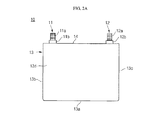
- FIG. 2A is a front view illustrating a secondary battery of a battery pack according to an embodiment
- FIG. 2B is a side view illustrating the secondary battery of FIG. 2A ;
- FIG. 2C is a plan view of the secondary battery of FIG. 2A .
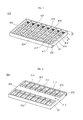
- FIG. 3 is a perspective view illustrating a first cover member of a battery pack according to an embodiment
- FIG. 4 is a perspective view illustrating a second cover member of a battery pack according to an embodiment
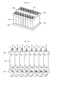
- FIG. 5A is a perspective view illustrating a battery pack according to an embodiment
- FIG. 5B is a side view illustrating the battery pack of FIG. 5A ;
- FIGS. 6A through 6C are perspective views illustrating a process of assembling a battery pack as a secondary battery module according to an embodiment
- FIG. 7 is an exploded perspective view illustrating a battery pack according to an embodiment.
- FIG. 1 is an exploded perspective view illustrating a battery pack according to an embodiment.
- FIG. 2A is a front view illustrating a secondary battery constituting a battery pack according to an embodiment.
- FIG. 2B is a side view illustrating a secondary battery constituting a battery pack according to an embodiment.
- FIG. 2C is a bottom view illustrating a secondary battery constituting a battery pack according to an embodiment.
- FIG. 3 is a perspective view illustrating a first cover member of a battery pack according to an embodiment.
- FIG. 4 is a perspective view illustrating a second cover member of a battery pack according to an embodiment.
- FIG. 5A is a perspective view illustrating a battery pack according to an embodiment.
- FIG. 5B is a side view illustrating a battery pack according to an embodiment.
- a battery pack according to an embodiment includes a secondary battery module 100, a first cover member 400, and a second cover member 200.
- the secondary battery module 100 includes a plurality of secondary batteries 10, 20, 30, 40, 50, 60, 70, and 80, which are parallel and electrically connected to one another. There are eight secondary batteries 10, 20, 30, 40, 50, 60, 70, and 80 in the current embodiment, but embodiments of the present invention are not limited thereto.
- the secondary battery 10 includes an electrode assembly, a case 13, a cap plate 14, and collecting terminals 11 and 12.
- the electrode assembly may include a positive electrode plate, a separator, and a negative electrode plate.
- the positive electrode plate, the separator, and the negative electrode plate may be wound at a plurality of times in an approximately oval shape about a winding axis.
- the case 13 has an approximately hexahedron shape provided with an opening through which the electrode assembly, a positive terminal (also denoted by 11), and a negative terminal (also denoted by 12) are inserted and placed.
- the case 13 may be formed of one of aluminum (Al), copper (Cu), iron (Fe), stainless steel (SUS), a ceramic, a polymer material, and an equivalent thereof, but embodiments of the present invention are not limited thereto.
- the case 13 includes a first surface 13a that may include one or more coupling recesses 13a 1 and 13a 2 .
- the coupling recesses 13a 1 and 13a 2 may be coupled to first elastic members 430 of the first cover member 400 to be described later.
- the cap plate 14 is coupled to the case 13 to cover the electrode assembly.
- the cap plate 14 may be coupled to the case 13 using laser welding, resistance welding, or supersonic welding.
- the cap plate 14 may be formed of the same material as the case 13.
- a safety vent may be located on the cap plate 14. When an inner pressure of the case 13 is equal to or greater than an allowance value, the safety vent ruptures to emit inner gas to the outside.
- the safety vent may be thinner than the cap plate 14.
- the collecting terminals 11 and 12 include the positive terminal 11 and the negative terminal 12 which are coupled to and protrude from the cap plate 14.
- the positive terminal 11 and the negative terminal 12 are threaded to allow a bus bar to be coupled and fixed thereto.
- Terminal plates 11 b and 12b are coupled to upper regions 11 a and 12a of the positive terminal 11 and the negative terminal 12, respectively.
- the terminal plates 11 b and 12b may be nuts having a hexagonal column shape.
- the positive terminal 11 may be electrically connected through a collecting plate to the positive electrode plate of the electrode assembly and the negative terminal 12 may be electrically connected through a collecting plate to the negative electrode plate of the electrode assembly.
- the positive terminal 11 and the negative terminal 12 may be formed of aluminum (Al) and copper (Cu), respectively, but embodiments of the present invention are not limited thereto.
- the first cover member 400 covers first surfaces (that is, bottom surfaces) 13a, 23a, 33a, 43a, 53a, 63a, 73a, and 83a of the secondary batteries 10, 20, 30, 40, 50, 60, 70, and 80.
- the first elastic members 430 are located between the first cover member 400 and the respective first surfaces 13a, 23a, 33a, 43a, 53a, 63a, 73a, and 83a.
- the first elastic members 430 include coil springs 430a, 430b, 430c, 430d, 430e, 430f, 430g, and 430h ( FIG.
- the first elastic member may be elastically compressible in the direction between the first cover member and the first surface of the secondary batteries.
- the first elastic member 430 may be a coil spring, but embodiments of the present invention are not limited thereto. In such embodiments, a separate first elastic member (e.g. a coil spring) may be provided for each of the secondary batteries. In other embodiments, the first elastic member may be a single integral member for all or some of the secondary batteries.
- the first cover member 400 includes a first horizontal part 410 and a first sidewall part 420.
- the bottom surface of the first horizontal part 410 is substantially flat and may include a plurality of discharge holes 414 to discharge and introduce gas or water.
- the discharge holes 414 are surrounded by a plurality of sidewalls 411.
- the first sidewall part 420 extends in a first direction from edges of the first horizontal part 410 to second surfaces that are opposite to the first surfaces 13a, 23a, 33a, 43a, 53a, 63a, 73a, and 83a, that is, extends upward, and is perpendicular to the first horizontal part 410.
- the first sidewall part 420 includes sidewalls 421, 422, 423, and 424, which are perpendicular to the first horizontal part 410.
- the first horizontal part 410 may further include first vertical parts 412 that protrude in the first direction, so that the first vertical parts 412 can be fitted between the secondary batteries 10, 20, 30, 40, 50, 60, 70, and 80.
- the first vertical parts 412 may be located at a lower position than the first sidewall part 420, i.e., they may be recessed from the first sidewall part.
- the first vertical parts 412 contact the first surfaces 13a, 23a, 33a, 43a, 53a, 63a, 73a, and 83a of the secondary batteries 10, 20, 30, 40, 50, 60, 70, and 80, and the first sidewall part 420 surrounds the first surfaces 13a, 23a, 33a, 43a, 53a, 63a, 73a, and 83a, and side surfaces adjacent thereto. Accordingly, the first cover member 400 is coupled to the lower portions of the secondary batteries 10, 20, 30, 40, 50, 60, 70, and 80.
- the first horizontal part 410 includes positioning recesses 413 coupled to the coil springs (also denoted by 430).
- the positioning recesses 413 include the positioning recesses 413a, 413b, 413c, 413d, 413e, 413f, 413g, and 413h to correspond to a plurality of coil springs 430a, 430b, 430c, 430d, 430e, 430f, 430g, and 430h.
- the positioning recesses 413 may be located on both side portions of the top surface of the first horizontal part 410, but embodiments of the present invention are not limited thereto.
- the lower portion of the coil spring 430 is coupled to the inner portion of the positioning recess 413, and the upper portion thereof protrudes out of the positioning recess 413.
- the upper portions of the coil springs 430 contact coupling recesses (refer to FIG. 6C ) of the first surfaces 13a, 23a, 33a, 43a, 53a, 63a, 73a, and 83a to absorb shock or vibration applied from the outside of the secondary batteries 10, 20, 30, 40, 50, 60, 70, and 80, thereby improving the durability of the secondary batteries 10, 20, 30, 40, 50, 60, 70, and 80.
- the second cover member 200 includes through holes 214 through which collecting terminals 11, 21, 31, 41, 51, 61, 71, 81, 12, 22, 32, 42, 52, 62, 72, and 82 of the secondary batteries 10, 20, 30, 40, 50, 60, 70, and 80 constituting the secondary battery module 100 pass, and surrounds the second surfaces that are opposite to the first surfaces 13a, 23a, 33a, 43a, 53a, 63a, 73a, and 83a, that is, surrounds the top surfaces of the secondary batteries 10, 20, 30, 40, 50, 60, 70, and 80.
- the through holes 214 may have a circular shape and a polygonal shape such as a tetragonal shape, from a plan view, but embodiments of the present invention are not limited thereto.
- the second cover member 200 may be formed of one of aluminum (Al), copper (Cu), iron (Fe), stainless steel (SUS), a ceramic, a polymer material, and an equivalent thereof, but embodiments of the present invention are not limited thereto.
- the second cover member 200 includes a second horizontal part 210 and a second sidewall part 220, wherein the through holes 214 are located in the second horizontal part 210.
- a top surface 211 of the second horizontal part 210 is flat and the second sidewall part 220 extends in a second direction extending from edges of the second horizontal part 210 to the first surfaces 13a, 23a, 33a, 43a, 53a, 63a, 73a, and 83a, that is, extends downward, and includes sidewalls 221, 222, 223, and 224, which are substantially perpendicular to the second horizontal part 210.
- the second horizontal part 210 may further include second vertical parts 212 that protrude in the second direction, so that the second vertical parts 212 can be fitted between neighboring secondary batteries 10, 20, 30, 40, 50, 60, 70, and 80.
- the second vertical parts 212 may be located at a higher position than the second sidewall part 220.
- the second vertical parts 212 contact the second surfaces of the secondary batteries 10, 20, 30, 40, 50, 60, 70, and 80, and the second sidewall part 220 surrounds the second surfaces and side surfaces adjacent to the second surfaces, so that the second cover member 200 is fixed to the upper portion of the secondary batteries 10, 20, 30, 40, 50, 60, 70, and 80.
- the second horizontal part 210 may further include horizontal members 213 that are perpendicular to the second vertical parts 212 and pass through the second vertical parts 212 and the second sidewall part 220.
- a second elastic member 300 may be located between the second cover member 200 and the second surfaces of the secondary batteries 10, 20, 30, 40, 50, 60, 70, and 80.
- the second elastic member 300 may be a leaf spring, but embodiments of the present invention are not limited thereto.
- the second elastic member may be elastically compressible in the direction between the second cover member and the second surface of the secondary batteries.
- a separate second elastic member may be provided for each of the secondary batteries.
- the second elastic member may be a single integral member for all or some of the secondary batteries.
- the second elastic member 300 (hereinafter, referred to as a leaf spring) extends in an array direction of the secondary batteries 10, 20, 30, 40, 50, 60, 70, and 80, and absorbs shock and vibration applied from the outside of the second cover member 200 to protect the secondary batteries 10, 20, 30, 40, 50, 60, 70, and 80, thereby improving the durability thereof.
- the leaf spring 300 may be formed of a copper alloy having high elasticity, such as one of phosphorus bronze, beryllium copper, and brass, but embodiments of the present invention are not limited thereto.
- the collecting terminals of neighboring ones of the secondary batteries 10, 20, 30, 40, 50, 60, 70, and 80 may be connected to each another through bus bars.
- one of the bus bars denoted by 510 in FIG. 7 , may electrically connect the collecting terminal 12 of the secondary battery 10 to the collecting terminal 22 of the secondary battery 20 adjacent thereto.
- the leaf spring 300 contacts the top surface of the bus bar 510 and the bottom surface of the second horizontal part 210 of the second cover member 200, which will be described later with reference to FIG. 7 .
- the flatness, durability and assembly quality of the secondary batteries can be ensured, and further, swelling due to inner pressure increased during the charging and discharging of the secondary batteries is prevented more efficiently.
- FIGS. 6A through 6C are perspective views illustrating a process of assembling a battery pack with a secondary battery module according to an embodiment.
- the leaf spring 300 is coupled to the secondary battery module 100 in which the secondary batteries 10, 20, 30, 40, 50, 60, 70, and 80 are parallel and electrically connected to one another. That is, the leaf spring 300 extends in the array direction of the secondary batteries 10, 20, 30, 40, 50, 60, 70, and 80 is located between a group of the positive terminals 11, 21, 31, 41, 51, 61, 71, and 81, and a group of the negative terminals 12, 22, 32, 42, 52, 62, 72, and 82, which are located on the second surfaces (top surfaces) of the secondary batteries 10, 20, 30, 40, 50, 60, 70, and 80.
- the cover member 200 is coupled to both the secondary battery module 100 and the leaf spring 300. That is, the second horizontal part 210 of the cover member 200 closely contacts the leaf spring 300, and the positive terminals 11, 21, 31, 41, 51, 61, 71, and 81, and the negative terminals 12, 22, 32, 42, 52, 62, 72, and 82 pass through the through holes 214, and the second sidewall part 220 surrounds the upper edges of the secondary battery module 100.
- the first cover member 400 is coupled to the lower portion of the secondary battery module 100.
- the coil springs 430a, 430b, 430c, 430d, 430e, 430f, 430g, and 430h are located in the positioning recesses 413a, 413b, 413c, 413d, 413e, 413f, 413g, and 413h of the first cover member 400, and are coupled to coupling recesses 13a 1 , 23a 1 , 33a 1 , 43a 1 , 53a 1 , 63a 1 , 73a 1 , and 83a 1 formed in the first surfaces 13a, 23a, 33a, 43a, 53a, 63a, 73a, and 83a.
- FIG. 7 is an exploded perspective view illustrating a battery pack according to an embodiment.
- a battery pack according to an embodiment includes a secondary battery module 100, a first cover member 400, and a second cover member 200. Since the first and second cover members 400 and 200 of the battery pack of FIG. 7 are the same as the first and second cover members 400 and 200 of the battery pack of FIGS. 1 through 5B , the battery pack of FIG. 7 according to the current embodiment will now be described with respect to the secondary battery module 100.
- the secondary battery module 100 is formed by placing the secondary batteries 10, 20, 30, 40, 50, 60, 70, and 80 parallel to one another, and electrically connecting the secondary batteries 10, 20, 30, 40, 50, 60, 70, and 80 to one another through bus bars 510, 520, 530, 540, and 550.
- the secondary batteries 10, 20, 30, 40, 50, 60, 70, and 80 may be connected to one another in series and/or in parallel through the bus bars 510, 520, 530, 540, and 550, which are electrically conductive.
- the bus bars 510, 520, 530, 540, and 550 include through holes 511, 521, 531, 541, and 551 at both sides thereof, respectively.
- the through holes 511, 521, 531, 541, and 551 are coupled to the positive terminals 11, 21, 31, 41, 51, 61, 71, and 81 and the negative terminals 12, 22, 32, 42, 52, 62, 72, and 82 of the secondary batteries 10, 20, 30, 40, 50, 60, 70, and 80.
- the second surfaces of the secondary batteries 10, 20, 30, 40, 50, 60, 70, and 80 are coupled to the leaf spring 300 extending in the array direction thereof.
- the positive terminals 11, 21, 31, 41, 51, 81, 71, and 81 and the negative terminals 12, 22, 32, 42, 52, 62, 72, and 82 couple to nuts 512, 522, 532, 542, and 552, after passing through the bus bars 512, 522, 532, 542, and 552.
- the positive terminals 11, 21, 31, 41, 51, 61, 71, and 81 and the negative terminals 12, 22, 32, 42, 52, 62, 72, and 82 may be riveted to the bus bars 510, 520, 530, 540, and 550, after passing through the bus bars 510, 520, 530, 540, and 550.
- the top and bottom surfaces of the secondary battery module 100 configured as described above are coupled to the first and second cover members 200 and 400, respectively.
- the bus bars 510, 520, 530, 540, and 550 may be formed of one of stainless steel, aluminum, an aluminum alloy, copper, a copper alloy, and an equivalent thereof, but embodiments of the present invention are not limited thereto.
- the leaf spring is located between the top surfaces of the secondary batteries and the second cover member, and the coil spring is located between the bottom surface of each secondary battery and the first cover member, to absorb vibration, thereby improving the durability of the battery pack against external shock and vibration.
- the flatness, durability and assembly quality of the secondary batteries can be ensured, and further, swelling due to inner pressure increased during the charging and discharging of the secondary batteries is prevented more efficiently.
- the secondary battery can be coupled to a motor for propelling an electric vehicle or a hybrid electric vehicle. In doing so, the vehicle will be able to operate on less or no traditional fuel like gasoline, and therefore, be more environmentally friendly.
Landscapes
- Chemical & Material Sciences (AREA)
- Chemical Kinetics & Catalysis (AREA)
- Electrochemistry (AREA)
- General Chemical & Material Sciences (AREA)
- Inorganic Chemistry (AREA)
- Battery Mounting, Suspending (AREA)
- Connection Of Batteries Or Terminals (AREA)
Abstract
Description
- Embodiments relate to a battery pack.
- Hybrid or electric vehicles, which use an interaction between an engine and a motor, may include a secondary battery as a power device. For example, lithium ion secondary batteries, which are non-aqueous secondary batteries having high output and high energy density, are often used as power sources of electric vehicles.
- Such a secondary battery typically include: a case; an electrode assembly including a positive electrode plate, a separator, and a negative electrode plate; a positive terminal connected to the positive electrode plate; a negative terminal connected to the negative electrode plate; and a cap plate coupled to the case to receive electrolyte and the electrode assembly and fixing the positive terminal and the negative terminal. The cap plate may include a safety vent that ruptures and emits gas when a large amount of gas is generated during the charging or discharging of the battery.
- Such secondary batteries may be arranged in parallel, and may be connected to one another in parallel or in series to form a battery pack for generating high electric power.
- An aspect of the present invention provides a battery pack, in which the top and bottom surfaces of secondary batteries are coupled to flat first and second cover members, thereby ensuring the flatness, durability and assembly quality of the secondary batteries.
- Another aspect of the present invention provides a battery pack that includes elastic members between a cover member and the top surfaces of secondary batteries, and between the other cover member and the bottom surfaces of the secondary batteries, to absorb vibration, thereby improving the durability of the battery pack against external shock and vibration.
- According to at least one of embodiments, a battery pack includes a plurality of secondary batteries including: an electrode assembly; a case accommodating the electrode assembly; and a collecting terminal electrically connected to the electrode assembly and protruding out of the case; a first cover member surrounding a first surface of the secondary batteries; and a first elastic member disposed between the first cover member and the first surface of the secondary batteries. The first elastic member may be elastically compressible in a direction between the first cover member and the first surface of the secondary batteries. In some embodiments, the first elastic member may be a single integral member for all or some of the secondary batteries. In other embodiments, a separate first elastic member may be provided for each of the secondary batteries.
- The first cover member may include: a first horizontal part having a plurality discharge holes; and a first sidewall part extending in a first direction extending from an edge of the first horizontal part to a second surface that is opposite to the first surface. The first horizontal part may include a positioning recess that is coupled to the first elastic member. The first elastic member may include a coil spring. The first horizontal part may include a first vertical part that protrudes in the first direction such that the first vertical part is fitted between the secondary batteries. The first vertical part may be disposed at a lower position than the first sidewall part. The secondary batteries may have at least one coupling recess in the first surface. The first elastic member may be fitted in the coupling recess.
- The battery pack may further include a second cover member that has a through hole through which the collecting terminal passes, and that covers a second surface of the secondary batteries, and the second surface is opposite to the first surface. The battery pack may further include a second elastic member between the second cover member and the second surface of the secondary batteries. The second elastic member may include a leaf spring. The second elastic member may be elastically compressible in a direction between the second cover member and the second surface of the secondary batteries. In some embodiments, the second elastic member may be a single integral member for all or some of the secondary batteries. In other embodiments, a separate second elastic member may be provided for each of the secondary batteries.
- Collecting terminals of neighboring ones of the secondary batteries may be electrically connected to each other through a bus bar. The bus bar may be disposed between the second surface of the secondary batteries and the second elastic member.
- According to an aspect of the present invention, there is provided a battery pack as set out in claim 1. Preferred features of this aspect are set out in claims 2 to 14.
- The accompanying drawings are included to provide a further understanding of the present disclosure, and are incorporated in and constitute a part of this specification. The drawings illustrate exemplary embodiments of the present disclosure and, together with the description, serve to explain principles of the present disclosure. In the drawings:
-
FIG. 1 is an exploded perspective view illustrating a battery pack according to an embodiment; -
FIG. 2A is a front view illustrating a secondary battery of a battery pack according to an embodiment; -
FIG. 2B is a side view illustrating the secondary battery ofFIG. 2A ; -
FIG. 2C is a plan view of the secondary battery ofFIG. 2A . -
FIG. 3 is a perspective view illustrating a first cover member of a battery pack according to an embodiment; -
FIG. 4 is a perspective view illustrating a second cover member of a battery pack according to an embodiment; -
FIG. 5A is a perspective view illustrating a battery pack according to an embodiment; -
FIG. 5B is a side view illustrating the battery pack ofFIG. 5A ; -
FIGS. 6A through 6C are perspective views illustrating a process of assembling a battery pack as a secondary battery module according to an embodiment; and -
FIG. 7 is an exploded perspective view illustrating a battery pack according to an embodiment. - Example embodiments will now be described more fully hereinafter with reference to the accompanying drawings; however, they may be embodied in different forms and should not be construed as limited to the embodiments set forth herein. Rather, these embodiments are provided so that this disclosure will be thorough and complete, and will fully convey the scope of the invention to those skilled in the art.
- Hereinafter, embodiments will be described in detail with reference to the accompanying drawings.
-
FIG. 1 is an exploded perspective view illustrating a battery pack according to an embodiment.FIG. 2A is a front view illustrating a secondary battery constituting a battery pack according to an embodiment.FIG. 2B is a side view illustrating a secondary battery constituting a battery pack according to an embodiment.FIG. 2C is a bottom view illustrating a secondary battery constituting a battery pack according to an embodiment.FIG. 3 is a perspective view illustrating a first cover member of a battery pack according to an embodiment.FIG. 4 is a perspective view illustrating a second cover member of a battery pack according to an embodiment.FIG. 5A is a perspective view illustrating a battery pack according to an embodiment.FIG. 5B is a side view illustrating a battery pack according to an embodiment. - Referring to
FIGS. 1 and5B , a battery pack according to an embodiment includes asecondary battery module 100, afirst cover member 400, and asecond cover member 200. - The
secondary battery module 100 includes a plurality ofsecondary batteries secondary batteries - Referring to
FIGS. 2A to 2C , thesecondary battery 10 includes an electrode assembly, acase 13, acap plate 14, and collectingterminals - The electrode assembly may include a positive electrode plate, a separator, and a negative electrode plate. The positive electrode plate, the separator, and the negative electrode plate may be wound at a plurality of times in an approximately oval shape about a winding axis.
- The
case 13 has an approximately hexahedron shape provided with an opening through which the electrode assembly, a positive terminal (also denoted by 11), and a negative terminal (also denoted by 12) are inserted and placed. Thecase 13 may be formed of one of aluminum (Al), copper (Cu), iron (Fe), stainless steel (SUS), a ceramic, a polymer material, and an equivalent thereof, but embodiments of the present invention are not limited thereto. Thecase 13 includes afirst surface 13a that may include one ormore coupling recesses elastic members 430 of thefirst cover member 400 to be described later. - The
cap plate 14 is coupled to thecase 13 to cover the electrode assembly. For example, thecap plate 14 may be coupled to thecase 13 using laser welding, resistance welding, or supersonic welding. Thecap plate 14 may be formed of the same material as thecase 13. A safety vent may be located on thecap plate 14. When an inner pressure of thecase 13 is equal to or greater than an allowance value, the safety vent ruptures to emit inner gas to the outside. The safety vent may be thinner than thecap plate 14. - The collecting
terminals positive terminal 11 and thenegative terminal 12 which are coupled to and protrude from thecap plate 14. Thepositive terminal 11 and thenegative terminal 12 are threaded to allow a bus bar to be coupled and fixed thereto.Terminal plates upper regions positive terminal 11 and thenegative terminal 12, respectively. Theterminal plates positive terminal 11 may be electrically connected through a collecting plate to the positive electrode plate of the electrode assembly and thenegative terminal 12 may be electrically connected through a collecting plate to the negative electrode plate of the electrode assembly. Thepositive terminal 11 and thenegative terminal 12 may be formed of aluminum (Al) and copper (Cu), respectively, but embodiments of the present invention are not limited thereto. - Referring to
FIG. 3 , thefirst cover member 400 covers first surfaces (that is, bottom surfaces) 13a, 23a, 33a, 43a, 53a, 63a, 73a, and 83a of thesecondary batteries elastic members 430 are located between thefirst cover member 400 and the respectivefirst surfaces elastic members 430 includecoil springs FIG. 5B ) to correspond to thefirst surfaces elastic member 430 may be a coil spring, but embodiments of the present invention are not limited thereto. In such embodiments, a separate first elastic member (e.g. a coil spring) may be provided for each of the secondary batteries. In other embodiments, the first elastic member may be a single integral member for all or some of the secondary batteries. - The
first cover member 400 includes a firsthorizontal part 410 and afirst sidewall part 420. The bottom surface of the firsthorizontal part 410 is substantially flat and may include a plurality of discharge holes 414 to discharge and introduce gas or water. The discharge holes 414 are surrounded by a plurality ofsidewalls 411. Thefirst sidewall part 420 extends in a first direction from edges of the firsthorizontal part 410 to second surfaces that are opposite to thefirst surfaces horizontal part 410. Thefirst sidewall part 420 includessidewalls horizontal part 410. The firsthorizontal part 410 may further include firstvertical parts 412 that protrude in the first direction, so that the firstvertical parts 412 can be fitted between thesecondary batteries vertical parts 412 may be located at a lower position than thefirst sidewall part 420, i.e., they may be recessed from the first sidewall part. The firstvertical parts 412 contact thefirst surfaces secondary batteries first sidewall part 420 surrounds thefirst surfaces first cover member 400 is coupled to the lower portions of thesecondary batteries - The first
horizontal part 410 includes positioning recesses 413 coupled to the coil springs (also denoted by 430). The positioning recesses 413 include thepositioning recesses coil springs horizontal part 410, but embodiments of the present invention are not limited thereto. The lower portion of thecoil spring 430 is coupled to the inner portion of thepositioning recess 413, and the upper portion thereof protrudes out of thepositioning recess 413. The upper portions of the coil springs 430 contact coupling recesses (refer toFIG. 6C ) of thefirst surfaces secondary batteries secondary batteries - Referring to
FIG. 4 , thesecond cover member 200 includes throughholes 214 through which collectingterminals secondary batteries secondary battery module 100 pass, and surrounds the second surfaces that are opposite to thefirst surfaces secondary batteries holes 214 may have a circular shape and a polygonal shape such as a tetragonal shape, from a plan view, but embodiments of the present invention are not limited thereto. Thesecond cover member 200 may be formed of one of aluminum (Al), copper (Cu), iron (Fe), stainless steel (SUS), a ceramic, a polymer material, and an equivalent thereof, but embodiments of the present invention are not limited thereto. - The
second cover member 200 includes a secondhorizontal part 210 and asecond sidewall part 220, wherein the throughholes 214 are located in the secondhorizontal part 210. Atop surface 211 of the secondhorizontal part 210 is flat and thesecond sidewall part 220 extends in a second direction extending from edges of the secondhorizontal part 210 to thefirst surfaces sidewalls horizontal part 210. The secondhorizontal part 210 may further include secondvertical parts 212 that protrude in the second direction, so that the secondvertical parts 212 can be fitted between neighboringsecondary batteries vertical parts 212 may be located at a higher position than thesecond sidewall part 220. Thus, the secondvertical parts 212 contact the second surfaces of thesecondary batteries second sidewall part 220 surrounds the second surfaces and side surfaces adjacent to the second surfaces, so that thesecond cover member 200 is fixed to the upper portion of thesecondary batteries horizontal part 210 may further includehorizontal members 213 that are perpendicular to the secondvertical parts 212 and pass through the secondvertical parts 212 and thesecond sidewall part 220. - A second
elastic member 300 may be located between thesecond cover member 200 and the second surfaces of thesecondary batteries elastic member 300 may be a leaf spring, but embodiments of the present invention are not limited thereto. The second elastic member may be elastically compressible in the direction between the second cover member and the second surface of the secondary batteries. A separate second elastic member may be provided for each of the secondary batteries. In other embodiments, the second elastic member may be a single integral member for all or some of the secondary batteries. The second elastic member 300 (hereinafter, referred to as a leaf spring) extends in an array direction of thesecondary batteries second cover member 200 to protect thesecondary batteries leaf spring 300 may be formed of a copper alloy having high elasticity, such as one of phosphorus bronze, beryllium copper, and brass, but embodiments of the present invention are not limited thereto. - The collecting terminals of neighboring ones of the
secondary batteries FIG. 7 , may electrically connect the collectingterminal 12 of thesecondary battery 10 to the collectingterminal 22 of thesecondary battery 20 adjacent thereto. Theleaf spring 300 contacts the top surface of thebus bar 510 and the bottom surface of the secondhorizontal part 210 of thesecond cover member 200, which will be described later with reference toFIG. 7 . - According to the embodiment, since the top and bottom surfaces of the batteries are coupled to the flat first and second cover members, the flatness, durability and assembly quality of the secondary batteries can be ensured, and further, swelling due to inner pressure increased during the charging and discharging of the secondary batteries is prevented more efficiently.
-
FIGS. 6A through 6C are perspective views illustrating a process of assembling a battery pack with a secondary battery module according to an embodiment. - Referring to
FIG. 6A , theleaf spring 300 is coupled to thesecondary battery module 100 in which thesecondary batteries leaf spring 300 extends in the array direction of thesecondary batteries positive terminals negative terminals secondary batteries - Referring to
FIG. 6B , thecover member 200 is coupled to both thesecondary battery module 100 and theleaf spring 300. That is, the secondhorizontal part 210 of thecover member 200 closely contacts theleaf spring 300, and thepositive terminals negative terminals holes 214, and thesecond sidewall part 220 surrounds the upper edges of thesecondary battery module 100. - Referring to
FIG. 6C , thefirst cover member 400 is coupled to the lower portion of thesecondary battery module 100. At this point, thecoil springs positioning recesses first cover member 400, and are coupled tocoupling recesses first surfaces -
FIG. 7 is an exploded perspective view illustrating a battery pack according to an embodiment. - Referring to
FIG. 7 , a battery pack according to an embodiment includes asecondary battery module 100, afirst cover member 400, and asecond cover member 200. Since the first andsecond cover members FIG. 7 are the same as the first andsecond cover members FIGS. 1 through 5B , the battery pack ofFIG. 7 according to the current embodiment will now be described with respect to thesecondary battery module 100. - The
secondary battery module 100 is formed by placing thesecondary batteries secondary batteries bus bars secondary batteries holes holes positive terminals negative terminals secondary batteries secondary batteries leaf spring 300 extending in the array direction thereof. Thepositive terminals negative terminals nuts positive terminals negative terminals secondary battery module 100 configured as described above are coupled to the first andsecond cover members - Thus, according to one embodiment, the leaf spring is located between the top surfaces of the secondary batteries and the second cover member, and the coil spring is located between the bottom surface of each secondary battery and the first cover member, to absorb vibration, thereby improving the durability of the battery pack against external shock and vibration.
- According to such an embodiment, since the top and bottom surfaces of the batteries are coupled to the flat first and second cover members, the flatness, durability and assembly quality of the secondary batteries can be ensured, and further, swelling due to inner pressure increased during the charging and discharging of the secondary batteries is prevented more efficiently.
- As will be appreciated, the secondary battery can be coupled to a motor for propelling an electric vehicle or a hybrid electric vehicle. In doing so, the vehicle will be able to operate on less or no traditional fuel like gasoline, and therefore, be more environmentally friendly.
- Exemplary embodiments have been disclosed herein, and although specific terms are employed, they are used and are to be interpreted in a generic and descriptive sense only and not for purpose of limitation. Accordingly, it will be understood by those of ordinary skill in the art that various changes in form and details may be made without departing from the scope of the present disclosure as set forth in the following claims.
Claims (14)
- A battery pack comprising:a plurality of secondary batteries, each of the secondary batteries including: an electrode assembly; a case accommodating the electrode assembly; and a collecting terminal electrically connected to the electrode assembly and protruding from the case;a first cover member on a first surface of each of the secondary batteries; anda first elastic member located between the first cover member and the first surface of each of the secondary batteries.
- A battery pack according to claim 1, wherein a separate first elastic member is provided for each of the secondary batteries.
- A battery pack according to claim 1 or 2, wherein each first elastic member comprises a coil spring.
- A battery pack according to any one of claims 1 to 3, wherein the first cover member comprises:a first part having a plurality discharge holes; anda first sidewall part extending in a first direction from an edge of the first part.
- A battery pack according to claim 4, wherein the first part comprises a positioning recess that accommodates each first elastic member.
- A battery pack according to claim 4 or 5, wherein the first part comprises a plurality of first protruding parts that protrude in the first direction such that a first protruding part is located between adjacent ones of the secondary batteries.
- A battery pack according to claim 6, wherein each first protruding part is recessed from the first sidewall part.
- A battery pack according to any one of claims 1 to 7, wherein each of the secondary batteries has at least one coupling recess in the first surface.
- A battery pack according to claim 8, wherein the first elastic member is located in the at least one coupling recess.
- A battery pack according to any one of claims 1 to 9, further comprising a second cover member that has a through hole through which each collecting terminal passes, and that covers a second surface of each of the secondary batteries, wherein the second surface is opposite to the first surface.
- A battery pack according to claim 10, further comprising a second elastic member located between the second cover member and the second surface of each of the secondary batteries.
- A battery pack according to claim 11, wherein the second elastic member comprises a leaf spring.
- A battery pack according to claim 11 or 12, wherein collecting terminals of adjacent ones of the secondary batteries are electrically connected to each other through a bus bar.
- A battery pack according to claim 13, wherein the bus bar is located between the second surface of the secondary batteries and the second elastic member.
Applications Claiming Priority (1)
| Application Number | Priority Date | Filing Date | Title |
|---|---|---|---|
| KR1020110030632A KR101264512B1 (en) | 2011-04-04 | 2011-04-04 | Battery Pack |
Publications (2)
| Publication Number | Publication Date |
|---|---|
| EP2509135A1 true EP2509135A1 (en) | 2012-10-10 |
| EP2509135B1 EP2509135B1 (en) | 2015-05-13 |
Family
ID=45894342
Family Applications (1)
| Application Number | Title | Priority Date | Filing Date |
|---|---|---|---|
| EP20120162260 Not-in-force EP2509135B1 (en) | 2011-04-04 | 2012-03-29 | Rechargeable battery with improved durability against external shock and vibration |
Country Status (3)
| Country | Link |
|---|---|
| US (1) | US20120251872A1 (en) |
| EP (1) | EP2509135B1 (en) |
| KR (1) | KR101264512B1 (en) |
Families Citing this family (11)
| Publication number | Priority date | Publication date | Assignee | Title |
|---|---|---|---|---|
| US9276243B2 (en) * | 2013-08-30 | 2016-03-01 | King Products, LLC | Battery holder and isolation assembly |
| KR102211365B1 (en) | 2014-04-14 | 2021-02-03 | 삼성에스디아이 주식회사 | Secondary battery |
| EP3133669B1 (en) | 2014-10-07 | 2019-12-04 | LG Chem, Ltd. | Battery module having improved safety and operational lifespan |
| KR102711972B1 (en) | 2018-10-08 | 2024-10-02 | 삼성에스디아이 주식회사 | Battery pack |
| KR102711971B1 (en) | 2018-10-08 | 2024-10-02 | 삼성에스디아이 주식회사 | Battery pack |
| KR102617730B1 (en) * | 2018-10-08 | 2023-12-26 | 삼성에스디아이 주식회사 | Battery pack |
| KR102220898B1 (en) | 2018-10-17 | 2021-02-26 | 삼성에스디아이 주식회사 | Battery pack |
| CN112310534B (en) | 2019-12-27 | 2021-10-15 | 宁德时代新能源科技股份有限公司 | Separator assembly, battery module, battery pack, device, and method of manufacture |
| DE102020201494B3 (en) * | 2020-02-07 | 2021-03-11 | Volkswagen Aktiengesellschaft | High-voltage battery for an electrically powered vehicle |
| US12555865B2 (en) * | 2020-03-16 | 2026-02-17 | Volvo Car Corporation | Cover for a battery module |
| CN112615104B (en) * | 2020-12-18 | 2022-03-22 | 江苏拓米洛环境试验设备有限公司 | A battery box pressure relief device |
Citations (3)
| Publication number | Priority date | Publication date | Assignee | Title |
|---|---|---|---|---|
| GB2297645A (en) * | 1995-02-06 | 1996-08-07 | Radiodetection Ltd | Battery housing comprising a pair of resilient contacts |
| WO2009136240A1 (en) * | 2008-05-08 | 2009-11-12 | Toyota Jidosha Kabushiki Kaisha | Cell holding device, assembled battery, and vehicle |
| JP2011034730A (en) * | 2009-07-30 | 2011-02-17 | Toshiba Corp | Battery pack |
Family Cites Families (7)
| Publication number | Priority date | Publication date | Assignee | Title |
|---|---|---|---|---|
| JPH0430775Y2 (en) * | 1986-05-29 | 1992-07-24 | Asahi Optical Co Ltd | |
| JP3848565B2 (en) * | 2001-11-27 | 2006-11-22 | 松下電器産業株式会社 | Battery connection structure, battery module, and battery pack |
| JP4361384B2 (en) * | 2004-01-29 | 2009-11-11 | セイコーインスツル株式会社 | Portable electronic device with sound reporting function |
| TW200830609A (en) * | 2007-01-04 | 2008-07-16 | Wen-Chin Shiau | Double-side usable modularized battery case |
| JP5139745B2 (en) * | 2007-08-10 | 2013-02-06 | 矢崎総業株式会社 | Power supply |
| JP5155772B2 (en) | 2008-08-19 | 2013-03-06 | 三菱重工業株式会社 | Battery pack structure |
| JP2010086784A (en) * | 2008-09-30 | 2010-04-15 | Toshiba Corp | Battery module |
-
2011
- 2011-04-04 KR KR1020110030632A patent/KR101264512B1/en not_active Expired - Fee Related
-
2012
- 2012-01-31 US US13/362,975 patent/US20120251872A1/en not_active Abandoned
- 2012-03-29 EP EP20120162260 patent/EP2509135B1/en not_active Not-in-force
Patent Citations (3)
| Publication number | Priority date | Publication date | Assignee | Title |
|---|---|---|---|---|
| GB2297645A (en) * | 1995-02-06 | 1996-08-07 | Radiodetection Ltd | Battery housing comprising a pair of resilient contacts |
| WO2009136240A1 (en) * | 2008-05-08 | 2009-11-12 | Toyota Jidosha Kabushiki Kaisha | Cell holding device, assembled battery, and vehicle |
| JP2011034730A (en) * | 2009-07-30 | 2011-02-17 | Toshiba Corp | Battery pack |
Also Published As
| Publication number | Publication date |
|---|---|
| KR101264512B1 (en) | 2013-05-14 |
| EP2509135B1 (en) | 2015-05-13 |
| KR20120112992A (en) | 2012-10-12 |
| US20120251872A1 (en) | 2012-10-04 |
Similar Documents
| Publication | Publication Date | Title |
|---|---|---|
| EP2509135B1 (en) | Rechargeable battery with improved durability against external shock and vibration | |
| KR101223568B1 (en) | Rechargeable battery and battery module | |
| US10243193B2 (en) | Battery pack | |
| JP6704060B2 (en) | Battery pack | |
| US10573871B2 (en) | Power supply device and bus bar for battery cell | |
| US11374277B2 (en) | Secondary battery pack | |
| US9231241B2 (en) | Battery pack | |
| KR100965684B1 (en) | Battery Pack | |
| US20120231309A1 (en) | Battery block and battery module | |
| EP3561902B1 (en) | Battery module, battery pack comprising battery module, and vehicle comprising battery pack | |
| US20140295235A1 (en) | Battery module | |
| US10367180B2 (en) | Battery pack | |
| US20160036088A1 (en) | Power source module | |
| US9178206B2 (en) | Battery module | |
| KR101916433B1 (en) | Battery Module | |
| US20140356664A1 (en) | Battery module | |
| US12183952B2 (en) | Battery pack with enhanced structure for preventing short circuit and shock | |
| JP7513013B2 (en) | Power storage device | |
| JP2009059681A (en) | Battery pack and battery case | |
| KR20160052018A (en) | Battery Module Having Mounting Means of Bus Bar and External Input-Output Terminal | |
| JP7318137B2 (en) | Mounting seat, battery and electrical equipment | |
| KR20180049799A (en) | Battery cell and method for manufacturing a battery cell | |
| CN115642371B (en) | Power storage device | |
| WO2025018322A1 (en) | Power storage device | |
| JP2011034730A (en) | Battery pack |
Legal Events
| Date | Code | Title | Description |
|---|---|---|---|
| PUAI | Public reference made under article 153(3) epc to a published international application that has entered the european phase |
Free format text: ORIGINAL CODE: 0009012 |
|
| 17P | Request for examination filed |
Effective date: 20120329 |
|
| AK | Designated contracting states |
Kind code of ref document: A1 Designated state(s): AL AT BE BG CH CY CZ DE DK EE ES FI FR GB GR HR HU IE IS IT LI LT LU LV MC MK MT NL NO PL PT RO RS SE SI SK SM TR |
|
| AX | Request for extension of the european patent |
Extension state: BA ME |
|
| RAP1 | Party data changed (applicant data changed or rights of an application transferred) |
Owner name: SAMSUNG SDI CO., LTD. Owner name: ROBERT BOSCH GMBH |
|
| GRAP | Despatch of communication of intention to grant a patent |
Free format text: ORIGINAL CODE: EPIDOSNIGR1 |
|
| RIC1 | Information provided on ipc code assigned before grant |
Ipc: H01M 2/20 20060101ALI20141029BHEP Ipc: H01M 2/10 20060101AFI20141029BHEP |
|
| INTG | Intention to grant announced |
Effective date: 20141126 |
|
| GRAS | Grant fee paid |
Free format text: ORIGINAL CODE: EPIDOSNIGR3 |
|
| GRAA | (expected) grant |
Free format text: ORIGINAL CODE: 0009210 |
|
| AK | Designated contracting states |
Kind code of ref document: B1 Designated state(s): AL AT BE BG CH CY CZ DE DK EE ES FI FR GB GR HR HU IE IS IT LI LT LU LV MC MK MT NL NO PL PT RO RS SE SI SK SM TR |
|
| REG | Reference to a national code |
Ref country code: GB Ref legal event code: FG4D |
|
| REG | Reference to a national code |
Ref country code: CH Ref legal event code: EP |
|
| REG | Reference to a national code |
Ref country code: IE Ref legal event code: FG4D |
|
| REG | Reference to a national code |
Ref country code: AT Ref legal event code: REF Ref document number: 727119 Country of ref document: AT Kind code of ref document: T Effective date: 20150615 |
|
| REG | Reference to a national code |
Ref country code: DE Ref legal event code: R096 Ref document number: 602012007260 Country of ref document: DE Effective date: 20150625 |
|
| REG | Reference to a national code |
Ref country code: AT Ref legal event code: MK05 Ref document number: 727119 Country of ref document: AT Kind code of ref document: T Effective date: 20150513 |
|
| REG | Reference to a national code |
Ref country code: NL Ref legal event code: MP Effective date: 20150513 |
|
| REG | Reference to a national code |
Ref country code: LT Ref legal event code: MG4D |
|
| PG25 | Lapsed in a contracting state [announced via postgrant information from national office to epo] |
Ref country code: PT Free format text: LAPSE BECAUSE OF FAILURE TO SUBMIT A TRANSLATION OF THE DESCRIPTION OR TO PAY THE FEE WITHIN THE PRESCRIBED TIME-LIMIT Effective date: 20150914 Ref country code: HR Free format text: LAPSE BECAUSE OF FAILURE TO SUBMIT A TRANSLATION OF THE DESCRIPTION OR TO PAY THE FEE WITHIN THE PRESCRIBED TIME-LIMIT Effective date: 20150513 Ref country code: LT Free format text: LAPSE BECAUSE OF FAILURE TO SUBMIT A TRANSLATION OF THE DESCRIPTION OR TO PAY THE FEE WITHIN THE PRESCRIBED TIME-LIMIT Effective date: 20150513 Ref country code: ES Free format text: LAPSE BECAUSE OF FAILURE TO SUBMIT A TRANSLATION OF THE DESCRIPTION OR TO PAY THE FEE WITHIN THE PRESCRIBED TIME-LIMIT Effective date: 20150513 Ref country code: FI Free format text: LAPSE BECAUSE OF FAILURE TO SUBMIT A TRANSLATION OF THE DESCRIPTION OR TO PAY THE FEE WITHIN THE PRESCRIBED TIME-LIMIT Effective date: 20150513 Ref country code: NO Free format text: LAPSE BECAUSE OF FAILURE TO SUBMIT A TRANSLATION OF THE DESCRIPTION OR TO PAY THE FEE WITHIN THE PRESCRIBED TIME-LIMIT Effective date: 20150813 |
|
| PG25 | Lapsed in a contracting state [announced via postgrant information from national office to epo] |
Ref country code: GR Free format text: LAPSE BECAUSE OF FAILURE TO SUBMIT A TRANSLATION OF THE DESCRIPTION OR TO PAY THE FEE WITHIN THE PRESCRIBED TIME-LIMIT Effective date: 20150814 Ref country code: AT Free format text: LAPSE BECAUSE OF FAILURE TO SUBMIT A TRANSLATION OF THE DESCRIPTION OR TO PAY THE FEE WITHIN THE PRESCRIBED TIME-LIMIT Effective date: 20150513 Ref country code: BG Free format text: LAPSE BECAUSE OF FAILURE TO SUBMIT A TRANSLATION OF THE DESCRIPTION OR TO PAY THE FEE WITHIN THE PRESCRIBED TIME-LIMIT Effective date: 20150813 Ref country code: IS Free format text: LAPSE BECAUSE OF FAILURE TO SUBMIT A TRANSLATION OF THE DESCRIPTION OR TO PAY THE FEE WITHIN THE PRESCRIBED TIME-LIMIT Effective date: 20150913 Ref country code: LV Free format text: LAPSE BECAUSE OF FAILURE TO SUBMIT A TRANSLATION OF THE DESCRIPTION OR TO PAY THE FEE WITHIN THE PRESCRIBED TIME-LIMIT Effective date: 20150513 Ref country code: RS Free format text: LAPSE BECAUSE OF FAILURE TO SUBMIT A TRANSLATION OF THE DESCRIPTION OR TO PAY THE FEE WITHIN THE PRESCRIBED TIME-LIMIT Effective date: 20150513 |
|
| PG25 | Lapsed in a contracting state [announced via postgrant information from national office to epo] |
Ref country code: DK Free format text: LAPSE BECAUSE OF FAILURE TO SUBMIT A TRANSLATION OF THE DESCRIPTION OR TO PAY THE FEE WITHIN THE PRESCRIBED TIME-LIMIT Effective date: 20150513 Ref country code: EE Free format text: LAPSE BECAUSE OF FAILURE TO SUBMIT A TRANSLATION OF THE DESCRIPTION OR TO PAY THE FEE WITHIN THE PRESCRIBED TIME-LIMIT Effective date: 20150513 |
|
| REG | Reference to a national code |
Ref country code: DE Ref legal event code: R097 Ref document number: 602012007260 Country of ref document: DE |
|
| REG | Reference to a national code |
Ref country code: FR Ref legal event code: PLFP Year of fee payment: 5 |
|
| PG25 | Lapsed in a contracting state [announced via postgrant information from national office to epo] |
Ref country code: PL Free format text: LAPSE BECAUSE OF FAILURE TO SUBMIT A TRANSLATION OF THE DESCRIPTION OR TO PAY THE FEE WITHIN THE PRESCRIBED TIME-LIMIT Effective date: 20150513 Ref country code: SK Free format text: LAPSE BECAUSE OF FAILURE TO SUBMIT A TRANSLATION OF THE DESCRIPTION OR TO PAY THE FEE WITHIN THE PRESCRIBED TIME-LIMIT Effective date: 20150513 Ref country code: CZ Free format text: LAPSE BECAUSE OF FAILURE TO SUBMIT A TRANSLATION OF THE DESCRIPTION OR TO PAY THE FEE WITHIN THE PRESCRIBED TIME-LIMIT Effective date: 20150513 Ref country code: RO Free format text: LAPSE BECAUSE OF NON-PAYMENT OF DUE FEES Effective date: 20150513 |
|
| PLBE | No opposition filed within time limit |
Free format text: ORIGINAL CODE: 0009261 |
|
| STAA | Information on the status of an ep patent application or granted ep patent |
Free format text: STATUS: NO OPPOSITION FILED WITHIN TIME LIMIT |
|
| 26N | No opposition filed |
Effective date: 20160216 |
|
| PG25 | Lapsed in a contracting state [announced via postgrant information from national office to epo] |
Ref country code: IT Free format text: LAPSE BECAUSE OF FAILURE TO SUBMIT A TRANSLATION OF THE DESCRIPTION OR TO PAY THE FEE WITHIN THE PRESCRIBED TIME-LIMIT Effective date: 20150513 |
|
| PG25 | Lapsed in a contracting state [announced via postgrant information from national office to epo] |
Ref country code: SI Free format text: LAPSE BECAUSE OF FAILURE TO SUBMIT A TRANSLATION OF THE DESCRIPTION OR TO PAY THE FEE WITHIN THE PRESCRIBED TIME-LIMIT Effective date: 20150513 |
|
| PG25 | Lapsed in a contracting state [announced via postgrant information from national office to epo] |
Ref country code: BE Free format text: LAPSE BECAUSE OF FAILURE TO SUBMIT A TRANSLATION OF THE DESCRIPTION OR TO PAY THE FEE WITHIN THE PRESCRIBED TIME-LIMIT Effective date: 20150513 |
|
| PG25 | Lapsed in a contracting state [announced via postgrant information from national office to epo] |
Ref country code: MC Free format text: LAPSE BECAUSE OF FAILURE TO SUBMIT A TRANSLATION OF THE DESCRIPTION OR TO PAY THE FEE WITHIN THE PRESCRIBED TIME-LIMIT Effective date: 20150513 Ref country code: LU Free format text: LAPSE BECAUSE OF FAILURE TO SUBMIT A TRANSLATION OF THE DESCRIPTION OR TO PAY THE FEE WITHIN THE PRESCRIBED TIME-LIMIT Effective date: 20160329 |
|
| REG | Reference to a national code |
Ref country code: CH Ref legal event code: PL |
|
| REG | Reference to a national code |
Ref country code: IE Ref legal event code: MM4A |
|
| PG25 | Lapsed in a contracting state [announced via postgrant information from national office to epo] |
Ref country code: CH Free format text: LAPSE BECAUSE OF NON-PAYMENT OF DUE FEES Effective date: 20160331 Ref country code: IE Free format text: LAPSE BECAUSE OF NON-PAYMENT OF DUE FEES Effective date: 20160329 Ref country code: LI Free format text: LAPSE BECAUSE OF NON-PAYMENT OF DUE FEES Effective date: 20160331 |
|
| REG | Reference to a national code |
Ref country code: FR Ref legal event code: PLFP Year of fee payment: 6 |
|
| PG25 | Lapsed in a contracting state [announced via postgrant information from national office to epo] |
Ref country code: SE Free format text: LAPSE BECAUSE OF FAILURE TO SUBMIT A TRANSLATION OF THE DESCRIPTION OR TO PAY THE FEE WITHIN THE PRESCRIBED TIME-LIMIT Effective date: 20150513 Ref country code: NL Free format text: LAPSE BECAUSE OF FAILURE TO SUBMIT A TRANSLATION OF THE DESCRIPTION OR TO PAY THE FEE WITHIN THE PRESCRIBED TIME-LIMIT Effective date: 20150513 |
|
| PG25 | Lapsed in a contracting state [announced via postgrant information from national office to epo] |
Ref country code: MT Free format text: LAPSE BECAUSE OF FAILURE TO SUBMIT A TRANSLATION OF THE DESCRIPTION OR TO PAY THE FEE WITHIN THE PRESCRIBED TIME-LIMIT Effective date: 20150513 |
|
| REG | Reference to a national code |
Ref country code: FR Ref legal event code: PLFP Year of fee payment: 7 |
|
| PG25 | Lapsed in a contracting state [announced via postgrant information from national office to epo] |
Ref country code: CY Free format text: LAPSE BECAUSE OF FAILURE TO SUBMIT A TRANSLATION OF THE DESCRIPTION OR TO PAY THE FEE WITHIN THE PRESCRIBED TIME-LIMIT Effective date: 20150513 Ref country code: HU Free format text: LAPSE BECAUSE OF FAILURE TO SUBMIT A TRANSLATION OF THE DESCRIPTION OR TO PAY THE FEE WITHIN THE PRESCRIBED TIME-LIMIT; INVALID AB INITIO Effective date: 20120329 Ref country code: SM Free format text: LAPSE BECAUSE OF FAILURE TO SUBMIT A TRANSLATION OF THE DESCRIPTION OR TO PAY THE FEE WITHIN THE PRESCRIBED TIME-LIMIT Effective date: 20150513 |
|
| PG25 | Lapsed in a contracting state [announced via postgrant information from national office to epo] |
Ref country code: TR Free format text: LAPSE BECAUSE OF FAILURE TO SUBMIT A TRANSLATION OF THE DESCRIPTION OR TO PAY THE FEE WITHIN THE PRESCRIBED TIME-LIMIT Effective date: 20150513 Ref country code: MT Free format text: LAPSE BECAUSE OF FAILURE TO SUBMIT A TRANSLATION OF THE DESCRIPTION OR TO PAY THE FEE WITHIN THE PRESCRIBED TIME-LIMIT Effective date: 20160331 Ref country code: MK Free format text: LAPSE BECAUSE OF FAILURE TO SUBMIT A TRANSLATION OF THE DESCRIPTION OR TO PAY THE FEE WITHIN THE PRESCRIBED TIME-LIMIT Effective date: 20150513 |
|
| PG25 | Lapsed in a contracting state [announced via postgrant information from national office to epo] |
Ref country code: AL Free format text: LAPSE BECAUSE OF FAILURE TO SUBMIT A TRANSLATION OF THE DESCRIPTION OR TO PAY THE FEE WITHIN THE PRESCRIBED TIME-LIMIT Effective date: 20150513 |
|
| REG | Reference to a national code |
Ref country code: DE Ref legal event code: R079 Ref document number: 602012007260 Country of ref document: DE Free format text: PREVIOUS MAIN CLASS: H01M0002100000 Ipc: H01M0050200000 |
|
| P01 | Opt-out of the competence of the unified patent court (upc) registered |
Effective date: 20230530 |
|
| PGFP | Annual fee paid to national office [announced via postgrant information from national office to epo] |
Ref country code: DE Payment date: 20240227 Year of fee payment: 13 Ref country code: GB Payment date: 20240229 Year of fee payment: 13 |
|
| PGFP | Annual fee paid to national office [announced via postgrant information from national office to epo] |
Ref country code: FR Payment date: 20240308 Year of fee payment: 13 |
|
| REG | Reference to a national code |
Ref country code: DE Ref legal event code: R119 Ref document number: 602012007260 Country of ref document: DE |
|
| GBPC | Gb: european patent ceased through non-payment of renewal fee |
Effective date: 20250329 |
|
| PG25 | Lapsed in a contracting state [announced via postgrant information from national office to epo] |
Ref country code: DE Free format text: LAPSE BECAUSE OF NON-PAYMENT OF DUE FEES Effective date: 20251001 |
|
| PG25 | Lapsed in a contracting state [announced via postgrant information from national office to epo] |
Ref country code: GB Free format text: LAPSE BECAUSE OF NON-PAYMENT OF DUE FEES Effective date: 20250329 |
|
| PG25 | Lapsed in a contracting state [announced via postgrant information from national office to epo] |
Ref country code: FR Free format text: LAPSE BECAUSE OF NON-PAYMENT OF DUE FEES Effective date: 20250331 |