EP2509088A1 - Snap key - Google Patents
Snap key Download PDFInfo
- Publication number
- EP2509088A1 EP2509088A1 EP11161636A EP11161636A EP2509088A1 EP 2509088 A1 EP2509088 A1 EP 2509088A1 EP 11161636 A EP11161636 A EP 11161636A EP 11161636 A EP11161636 A EP 11161636A EP 2509088 A1 EP2509088 A1 EP 2509088A1
- Authority
- EP
- European Patent Office
- Prior art keywords
- snap
- key
- accordance
- contact pad
- contact
- Prior art date
- Legal status (The legal status is an assumption and is not a legal conclusion. Google has not performed a legal analysis and makes no representation as to the accuracy of the status listed.)
- Withdrawn
Links
- 230000003993 interaction Effects 0.000 claims abstract description 34
- 229910052751 metal Inorganic materials 0.000 claims abstract description 11
- 239000002184 metal Substances 0.000 claims abstract description 11
- OKTJSMMVPCPJKN-UHFFFAOYSA-N Carbon Chemical compound [C] OKTJSMMVPCPJKN-UHFFFAOYSA-N 0.000 claims description 35
- 229910052799 carbon Inorganic materials 0.000 claims description 35
- XUIMIQQOPSSXEZ-UHFFFAOYSA-N Silicon Chemical compound [Si] XUIMIQQOPSSXEZ-UHFFFAOYSA-N 0.000 claims description 6
- 229910052710 silicon Inorganic materials 0.000 claims description 6
- 239000010703 silicon Substances 0.000 claims description 6
- 239000000463 material Substances 0.000 description 12
- 238000000034 method Methods 0.000 description 5
- 230000008569 process Effects 0.000 description 5
- 239000003575 carbonaceous material Substances 0.000 description 4
- PCHJSUWPFVWCPO-UHFFFAOYSA-N gold Chemical compound [Au] PCHJSUWPFVWCPO-UHFFFAOYSA-N 0.000 description 2
- 239000010931 gold Substances 0.000 description 2
- 229910052737 gold Inorganic materials 0.000 description 2
- 238000004519 manufacturing process Methods 0.000 description 2
- 229910000510 noble metal Inorganic materials 0.000 description 2
- 229910052709 silver Inorganic materials 0.000 description 2
- 239000004332 silver Substances 0.000 description 2
- 230000004913 activation Effects 0.000 description 1
- 230000002238 attenuated effect Effects 0.000 description 1
- 230000015556 catabolic process Effects 0.000 description 1
- 238000001311 chemical methods and process Methods 0.000 description 1
- 238000010276 construction Methods 0.000 description 1
- 238000006731 degradation reaction Methods 0.000 description 1
- 230000000593 degrading effect Effects 0.000 description 1
- 230000000694 effects Effects 0.000 description 1
- 239000011888 foil Substances 0.000 description 1
- 238000007654 immersion Methods 0.000 description 1
- 239000007769 metal material Substances 0.000 description 1
- 229910052755 nonmetal Inorganic materials 0.000 description 1
- 239000003973 paint Substances 0.000 description 1
- 230000009467 reduction Effects 0.000 description 1
- 239000004065 semiconductor Substances 0.000 description 1
- 238000007592 spray painting technique Methods 0.000 description 1
- 239000000126 substance Substances 0.000 description 1
Images


Classifications
-
- H—ELECTRICITY
- H01—ELECTRIC ELEMENTS
- H01H—ELECTRIC SWITCHES; RELAYS; SELECTORS; EMERGENCY PROTECTIVE DEVICES
- H01H5/00—Snap-action arrangements, i.e. in which during a single opening operation or a single closing operation energy is first stored and then released to produce or assist the contact movement
- H01H5/04—Energy stored by deformation of elastic members
- H01H5/30—Energy stored by deformation of elastic members by buckling of disc springs
-
- H—ELECTRICITY
- H01—ELECTRIC ELEMENTS
- H01H—ELECTRIC SWITCHES; RELAYS; SELECTORS; EMERGENCY PROTECTIVE DEVICES
- H01H13/00—Switches having rectilinearly-movable operating part or parts adapted for pushing or pulling in one direction only, e.g. push-button switch
- H01H13/02—Details
- H01H13/26—Snap-action arrangements depending upon deformation of elastic members
- H01H13/48—Snap-action arrangements depending upon deformation of elastic members using buckling of disc springs
-
- H—ELECTRICITY
- H01—ELECTRIC ELEMENTS
- H01H—ELECTRIC SWITCHES; RELAYS; SELECTORS; EMERGENCY PROTECTIVE DEVICES
- H01H2215/00—Tactile feedback
- H01H2215/004—Collapsible dome or bubble
-
- H—ELECTRICITY
- H01—ELECTRIC ELEMENTS
- H01H—ELECTRIC SWITCHES; RELAYS; SELECTORS; EMERGENCY PROTECTIVE DEVICES
- H01H2215/00—Tactile feedback
- H01H2215/034—Separate snap action
- H01H2215/036—Metallic disc
-
- H—ELECTRICITY
- H01—ELECTRIC ELEMENTS
- H01H—ELECTRIC SWITCHES; RELAYS; SELECTORS; EMERGENCY PROTECTIVE DEVICES
- H01H2227/00—Dimensions; Characteristics
- H01H2227/018—Printed contacts; Metal foil
-
- H—ELECTRICITY
- H01—ELECTRIC ELEMENTS
- H01H—ELECTRIC SWITCHES; RELAYS; SELECTORS; EMERGENCY PROTECTIVE DEVICES
- H01H2227/00—Dimensions; Characteristics
- H01H2227/026—Separate dome contact
- H01H2227/0261—Separate dome contact with an aperture in contact making centre of dome
Definitions
- the invention relates to a snap key including a metal snap disc as well as to a remote including two snap keys and a common cap.
- Snap keys are frequently used in keys of devices such as keyboards to generate a sound when an electrical impulse is being generated on the activation of a specific key.
- the snap key generates a sound to indicate to the user of the keyboard that the key has been actuated and that the key has been brought into an interaction position in which two separate contacts are brought into contact with one another to electrically interact.
- Such keyboards typically use noble metal contacts to produce the electrical interaction between the separate contacts when these are brought into contact.
- Such metal snap keys can be used reliably for up to more than five million cycles.
- a snap key in a preferred embodiment includes a metal snap disc having a raised portion with a hole formed at its center, wherein said snap disc is positioned on a support layer, wherein at least one contact area is formed at said support layer in a region of said raised portion and wherein said contact area is adapted to electrically interact with a contact pad when said contact pad is delivered into an interaction position at said hole.
- This interaction position is preferably selected such that the contact pad faces the contact area without actually touching the contact area and at the same time utilizes the space formed by said hole of said raised portion to be brought into the interaction position in which the contact pad is close enough to said contact area so that the electric interaction can take place.
- a metal snap disc having a hole at its center one advantageously maintains the characteristic sound of prior art keys, while at the same time allowing an electric interaction to take place in the region of said hole between the contact pad and said at least one contact area without the danger of the snap disc coming into contact with the contact area and thereby damaging it.
- This enables a significantly cheaper production of the snap key, as noble metal contacts can e.g. be replaced by simple carbon contacts.
- said contact pad penetrates said hole in said interaction position. This beneficially allows said contact pad to be brought closer to said contact area to improve the electrical interaction and at the same time not to engage either of the snap disc or the contact area.
- said contact pad does not contact said snap disc in said interaction position. This reduces the risk of e.g. a carbon contact pad being unnecessarily subjected to contacting metal material which would lead to a degradation of the contacts if these are non-metal and ultimately to a reduction of the lifetime of such snap keys.
- said snap key is actuated by a button.
- the button can also be used to move the contact pad from the rest position into the interaction position where it finally interacts with the contact area provided at the support layer.
- the contact pad is in the interaction position it is simply placed into a position within the hole of said snap disc, i.e. in a position where the contact pad fills up most of the space of the hole without actually touching the snap disc.
- the button can be used to place the contact pad into an interaction position in which it penetrates the hole of the snap disc.
- the button can be formed from silicon or any other type of plastic material which allows a cheap yet easily reproducible production of the snap key.
- the button contacts and interacts with said snap disc when said contact pad is delivered into said interaction position. This causes the characteristic sound of the key when the snap key is actuated and allows the generation of the characteristic sound when the electric interaction takes place between the contact pad and the contact areas.
- said button is integrated into a keypad and adapted to receive said snap disc, wherein preferably said keypad is a silicon keypad.
- a keypad is easy to reproduce and ensures that a compact design of the snap key is possible.
- a silicon keypad ensures that the button can be moved from a rest position into an interaction position and vice versa in a reliable manner.
- said contact pad is arranged at said button and said contact pad is possibly composed of a carbon material.
- a carbon contact pad is automatically moved into said interaction position from a rest position when said button is moved.
- arranging said carbon contact pad at said button permits the interaction path of the carbon contact pad to have the same length as the stroke height of the button without further complicated structures being required.
- said button has recesses provided to accommodate legs of said snap disc. In this way the snap key can be produced with an even smaller height allowing an even flatter design of the snap key.
- air channels are provided in said button. These can be formed such that the sound generated by the snap disc can not only be amplified, but also attenuated if specifically shaped air channels are used.
- said button is actuated by means of a cap and/or wherein said actuation of said button brings about said electrical interaction between said carbon contact pad and said at least one contact area.
- a cap to actuate said button prevents the possibly silicon button from degrading too quickly. It further permits like snap keys to be produced with individual finishing caps so that the same snap key type can be used when a plurality of snap keys are grouped together, but each key within a group of keys can have their own specific cap.
- said support layer is formed from a printed circuit board.
- a printed circuit board as a support layer permits the construction height of the snap key to be reduced.
- a material including carbon can be used for the contact area(s). It is preferred if this material is selected such that it is electrically interacting with said contact pad even when these are not in physical contact.
- carbon contact areas are selected to interact with a carbon contact pad.
- two contact areas are formed in a region of said raised portion and/or wherein said contact areas are carbon contact areas. Having two contact areas facilitates the signal transfer when the snap key is actuated. The first contact then permits a respective signal input and the second contact permits a respective signal output to and from the snap key when this is actuated.
- said snap disc is actuated with a force in the range of 1.5 N to 4 N and/or wherein said hole of said raised portion has a diameter of 0.5 to 12 mm and/or wherein said snap disc has a diameter in the range of from 5 mm to 20 mm.
- the outer shape of the snap disc can be arbitrarily selected in accordance with the type of application.
- the snap disc could have a generally polygonal outer shape such as a rectangle, or it could have a star like shape in which it e.g. has four feet which act as the apexes of the generally star shaped disc.
- the snap disc Independent of the kind of snap disc used it will have some form of base portion or feet which contact(s) the support layer having the contact areas.
- this includes a remote including two snap keys in accordance with the invention and a common cap, wherein said snap keys are actuatable by means of said common cap.
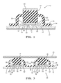
- Fig. 1 shows a schematic side view of a snap key 10.
- the snap key 10 is composed of a support layer 12 at which two contact areas 14 are formed beneath a raised portion 16 of a metal snap disc 18 which is placed onto the support layer 12.
- the snap disc 18 has a hole 20 at its center through which a carbon contact pad 22 may interact with the contact areas 14 when the carbon contact pad 22 is delivered into or through the hole 20 (or into a similar position adjacent said hole 20).
- the carbon contact pad 22 is attached to a switching dome 24 which acts as a button 24 to actuate the snap key 10.
- the button or dome 24 is integrated into a silicon keypad 26 enveloping both the snap disc 18 and the support layer 12. It should be noted that Fig. 1 shows two contact areas 14; however, it is naturally also possible to provide a plurality of contact areas 14 in dependence on the kind of application sought for the snap key 10.
- the carbon contact pad 22 moves from a rest position (not shown) into an interaction position in which the carbon contact pad 22 electrically interacts with the contact areas 14. In this interaction position the carbon contact pad 22 penetrates the hole 20 of the snap disc 18 and depending on the type of contact pad 22 and/or contact area 14 selected the spacing between the contact pad 22 and the contact area 14 can be selected so that the contact pad 22 projects through the hole 20 and or remains adjacent a lower side 28 of said hole 20. It should be noted that the carbon contact pad 22 does not actually contact the snap disc 18 in the embodiment of Fig. 1 , but on actuation of the switching dome 24 a part 30 of the button 24 contacts the snap disc 18 to move this.
- the sound characteristic for snap keys is generated 10 even though the electrical interaction is not brought about by means of metal contacting metal, but rather by means of at least one carbon contact electrically interacting with either the contact areas 14 or the contact pad 22.
- the carbon contact pad 22 can naturally also be formed such that it also contacts the snap disc 18.
- the snap disc 18 ensures that there is a return force present which returns the snap key 10 into the rest position.
- Fig. 2A shows a bottom view of a snap key 10. The outer contour of which is of generally round shape. An air channel 32 is formed at one side 34 thereof. A switching dome 24 is visible which has a portion having a generally rectangular shape. The switching dome 24 is shown in detail in Fig. 2B .
- Fig. 2B shows a section along the sectional line A-A of Fig. 2A .
- the button 24 has a generally square shaped switching dome 24 in section to which a carbon contact pad 22 is attached.
- the carbon contact pad 22 interacts with two carbon contact areas 14 when the button 24 is actuated and delivered from a rest position into an interaction position.
- the button 24 is activated the carbon contact pad 22 penetrates the hole 20 of the raised portion 16 of the snap disc 18 and the button 24 contacts the snap disc 18 to produce the characteristic sound.
- the button is released the inherent return force of the snap disc 18 causes the snap disc 18 to return into the rest position, causing the button 24 and the carbon contact pad 22 to move from the interaction position back into the rest position, thereby stopping the electrical interaction between the contact pad 22 and the contact areas 14.
- the carbon contact pad shown in Fig. 2B has a diameter of approximately 1 mm, however, this diameter can be selected in dependence on the type of application sought and suitable diameters for the carbon contact pad 22 can be selected in the range from 0.5 mm to 5 mm.
- the base portion 36 of the dome 24 is of generally rectangular shape in cross-section and has a height which can be selected in the range of approximately 0.7 mm to 1.5 mm and is internally configured to receive the snap disc 18.
- the overall height of the dome 24 is selected to be in the range from 3 to 6 mm.
- the stroke of the dome 24 is generally selected in the range from 0.1 mm to 1 mm.
- the precise dimensions of both the snap disc 18 and the dome 24 are selected in dependence of the type of application sought, i.e. the size of key required, the amplitude of the sound required and the number of cycles a snap key 10 is expected to sustain.
- Fig. 3 shows a schematic side view of an embodiment of a remote 38.
- two snap keys 10 in accordance with the invention are connected by means of a common cap 40.
- the snap key 10 can permit four types of signals to be transmitted from the contact areas 14 of the snap keys 10, a first type of signal stating that the common cap 40 has not been actuated and three types of signals all relating to different types of applications which can be selectively selected by the remote 38.
- Fig. 4A shows a schematic view of a generally rectangular shaped snap disc 18.
- Four legs/feet 42 of the snap disc 18 are respectively visible at each of the corners of the snap disc 18.
- the snap disc 18 has a raised portion 16 with a hole 20 formed at its center.
- Fig. 4B shows a section along the sectional line B-B of the snap disc 18 in accordance with Fig. 4A , one can see the raised portion 16 of the snap disc 18.
- the height of the raised portion 16 relative to the legs 42 of the snap disc 18 can be arbitrarily selected in accordance with the desired application.
- Fig. 4C shows a generally star like shaped snap disc 18, the four feet 42 of which act as the apexes of the snap disc 18.
- Fig. 4D shows a section along the sectional line C-C of Fig. 4C .
- the support layer 12 is preferably formed from a printed circuit board, but could also be a simple support structure 12 onto which an electronic circuit including the carbon contact areas 14 is bonded.
- the carbon contact areas 14 permit the signal transfer to and from the snap key 10 when the key 10 has been actuated by means of the switching dome 24.
- a contact area 14 can be formed from a material selected from the group including a carbon based electrically conductive paint, a carbon based electrically conductive ink, a printing ink, a conductive foil (MID), galvanic materials, chemical materials, gold, silver, metal contact material or such like.
- the material of the contact areas 14 is applied to the material of the support structure 12 by means of a spray painting process, an immersion process, a tampoprint process, a galvanic process a chemical process or a combined fluent process or such like.
- the contact pad 22 can be composed of a material selected from the group including carbon material, a high resistance carbon material, a low resistance carbon material, semiconducting material, gold, silver, metal contact material or such like. Generally speaking the material is selected such that a resistance of the contact pad is less than 100 Ohm preferably less than 20 Ohm, and most preferably less than 10 Ohm.
Landscapes
- Push-Button Switches (AREA)
Abstract
The present invention relates to a snap key including a metal snap disc having a raised portion with a hole formed at its center, wherein said snap disc is positioned on a support layer, wherein at least one contact area is formed at said support layer in a region of said raised portion and wherein said contact area is adapted to electrically interact with a contact pad when said contact pad is delivered into an interaction position at said hole. The invention further relates to a keypad including such snap keys.
Description
- The invention relates to a snap key including a metal snap disc as well as to a remote including two snap keys and a common cap.
- Snap keys are frequently used in keys of devices such as keyboards to generate a sound when an electrical impulse is being generated on the activation of a specific key. The snap key generates a sound to indicate to the user of the keyboard that the key has been actuated and that the key has been brought into an interaction position in which two separate contacts are brought into contact with one another to electrically interact. Such keyboards typically use noble metal contacts to produce the electrical interaction between the separate contacts when these are brought into contact. Such metal snap keys can be used reliably for up to more than five million cycles.
- It is an object of the present invention to provide a snap key at low cost while maintaining a characteristic sound on actuation of the key.
- This object is satisfied in accordance with claim 1.
- In a preferred embodiment a snap key includes a metal snap disc having a raised portion with a hole formed at its center, wherein said snap disc is positioned on a support layer, wherein at least one contact area is formed at said support layer in a region of said raised portion and wherein said contact area is adapted to electrically interact with a contact pad when said contact pad is delivered into an interaction position at said hole.
- This interaction position is preferably selected such that the contact pad faces the contact area without actually touching the contact area and at the same time utilizes the space formed by said hole of said raised portion to be brought into the interaction position in which the contact pad is close enough to said contact area so that the electric interaction can take place.
- Utilizing a metal snap disc having a hole at its center one advantageously maintains the characteristic sound of prior art keys, while at the same time allowing an electric interaction to take place in the region of said hole between the contact pad and said at least one contact area without the danger of the snap disc coming into contact with the contact area and thereby damaging it. This enables a significantly cheaper production of the snap key, as noble metal contacts can e.g. be replaced by simple carbon contacts.
- In an embodiment said contact pad penetrates said hole in said interaction position. This beneficially allows said contact pad to be brought closer to said contact area to improve the electrical interaction and at the same time not to engage either of the snap disc or the contact area.
- In an embodiment said contact pad does not contact said snap disc in said interaction position. This reduces the risk of e.g. a carbon contact pad being unnecessarily subjected to contacting metal material which would lead to a degradation of the contacts if these are non-metal and ultimately to a reduction of the lifetime of such snap keys.
- Advantageously said snap key is actuated by a button. This beneficially permits the snap key to be moved from a rest position into the interaction position. When the snap key is moved from the rest position into the interaction position the button can also be used to move the contact pad from the rest position into the interaction position where it finally interacts with the contact area provided at the support layer. When the contact pad is in the interaction position it is simply placed into a position within the hole of said snap disc, i.e. in a position where the contact pad fills up most of the space of the hole without actually touching the snap disc. Alternatively, the button can be used to place the contact pad into an interaction position in which it penetrates the hole of the snap disc. The button can be formed from silicon or any other type of plastic material which allows a cheap yet easily reproducible production of the snap key.
- Preferably, the button contacts and interacts with said snap disc when said contact pad is delivered into said interaction position. This causes the characteristic sound of the key when the snap key is actuated and allows the generation of the characteristic sound when the electric interaction takes place between the contact pad and the contact areas.
- In an embodiment said button is integrated into a keypad and adapted to receive said snap disc, wherein preferably said keypad is a silicon keypad. Such a keypad is easy to reproduce and ensures that a compact design of the snap key is possible. Moreover, a silicon keypad ensures that the button can be moved from a rest position into an interaction position and vice versa in a reliable manner.
- In an embodiment said contact pad is arranged at said button and said contact pad is possibly composed of a carbon material. Thereby such a carbon contact pad is automatically moved into said interaction position from a rest position when said button is moved. In addition, if a specific stroke height of the button, i.e. a specific length of movement of the button between said rest position and said interaction position, is desired, then arranging said carbon contact pad at said button permits the interaction path of the carbon contact pad to have the same length as the stroke height of the button without further complicated structures being required.
- In an embodiment said button has recesses provided to accommodate legs of said snap disc. In this way the snap key can be produced with an even smaller height allowing an even flatter design of the snap key.
- In an embodiment air channels are provided in said button. These can be formed such that the sound generated by the snap disc can not only be amplified, but also attenuated if specifically shaped air channels are used.
- In an embodiment said button is actuated by means of a cap and/or wherein said actuation of said button brings about said electrical interaction between said carbon contact pad and said at least one contact area. Using a cap to actuate said button prevents the possibly silicon button from degrading too quickly. It further permits like snap keys to be produced with individual finishing caps so that the same snap key type can be used when a plurality of snap keys are grouped together, but each key within a group of keys can have their own specific cap.
- In an embodiment said support layer is formed from a printed circuit board. Using a printed circuit board as a support layer permits the construction height of the snap key to be reduced. Furthermore, preferably a material including carbon can be used for the contact area(s). It is preferred if this material is selected such that it is electrically interacting with said contact pad even when these are not in physical contact. Preferably, carbon contact areas are selected to interact with a carbon contact pad.
- In an embodiment two contact areas are formed in a region of said raised portion and/or wherein said contact areas are carbon contact areas. Having two contact areas facilitates the signal transfer when the snap key is actuated. The first contact then permits a respective signal input and the second contact permits a respective signal output to and from the snap key when this is actuated.
- In an embodiment said snap disc is actuated with a force in the range of 1.5 N to 4 N and/or wherein said hole of said raised portion has a diameter of 0.5 to 12 mm and/or wherein said snap disc has a diameter in the range of from 5 mm to 20 mm.
- These are suitable parameters for the design of the snap disc. It should be noted that the outer shape of the snap disc can be arbitrarily selected in accordance with the type of application. For example, the snap disc could have a generally polygonal outer shape such as a rectangle, or it could have a star like shape in which it e.g. has four feet which act as the apexes of the generally star shaped disc. Independent of the kind of snap disc used it will have some form of base portion or feet which contact(s) the support layer having the contact areas.
- In a further aspect of the invention this includes a remote including two snap keys in accordance with the invention and a common cap, wherein said snap keys are actuatable by means of said common cap.
- The advantageous features are described in an exemplary manner only and are not intended to restrict the snap key in accordance with the invention or the keypad in accordance with the invention in any way.
- The invention will be described in the following with regard to further features and advantages by way of examples with reference to embodiments in the enclosed drawings. The Figures of the drawings show:
-
Fig. 1 a schematic side view of a snap key in accordance with the invention, -
Fig. 2A a schematic bottom view of a button, -
Fig. 2B a sectional view along the sectional line A-A ofFig. 2A , -
Fig. 3 a schematic side view of a remote in accordance with the invention, -
Fig. 4A a schematic view of a snap disc, -
Fig. 4B a sectional view along the line B-B ofFig. 4A , -
Fig. 4C a further schematic view of a snap disc, and -
Fig. 4D a sectional view along the line C-C ofFig. 4C . - Features having the same or similar function will be described in the following using the same reference numerals.
-
Fig. 1 shows a schematic side view of asnap key 10. Thesnap key 10 is composed of asupport layer 12 at which twocontact areas 14 are formed beneath a raisedportion 16 of ametal snap disc 18 which is placed onto thesupport layer 12. Thesnap disc 18 has ahole 20 at its center through which acarbon contact pad 22 may interact with thecontact areas 14 when thecarbon contact pad 22 is delivered into or through the hole 20 (or into a similar position adjacent said hole 20). Thecarbon contact pad 22 is attached to a switchingdome 24 which acts as abutton 24 to actuate thesnap key 10. The button ordome 24 is integrated into asilicon keypad 26 enveloping both thesnap disc 18 and thesupport layer 12. It should be noted thatFig. 1 shows twocontact areas 14; however, it is naturally also possible to provide a plurality ofcontact areas 14 in dependence on the kind of application sought for thesnap key 10. - On actuation of the
button 24 thecarbon contact pad 22 moves from a rest position (not shown) into an interaction position in which thecarbon contact pad 22 electrically interacts with thecontact areas 14. In this interaction position thecarbon contact pad 22 penetrates thehole 20 of thesnap disc 18 and depending on the type ofcontact pad 22 and/orcontact area 14 selected the spacing between thecontact pad 22 and thecontact area 14 can be selected so that thecontact pad 22 projects through thehole 20 and or remains adjacent alower side 28 of saidhole 20. It should be noted that thecarbon contact pad 22 does not actually contact thesnap disc 18 in the embodiment ofFig. 1 , but on actuation of the switching dome 24 apart 30 of thebutton 24 contacts thesnap disc 18 to move this. Thereby the sound characteristic for snap keys is generated 10 even though the electrical interaction is not brought about by means of metal contacting metal, but rather by means of at least one carbon contact electrically interacting with either thecontact areas 14 or thecontact pad 22. It should further be noted that, in contrast to the embodiment shown inFig. 1 , thecarbon contact pad 22 can naturally also be formed such that it also contacts thesnap disc 18. Moreover, thesnap disc 18 ensures that there is a return force present which returns the snap key 10 into the rest position. -
Fig. 2A shows a bottom view of asnap key 10. The outer contour of which is of generally round shape. Anair channel 32 is formed at oneside 34 thereof. A switchingdome 24 is visible which has a portion having a generally rectangular shape. The switchingdome 24 is shown in detail inFig. 2B . -
Fig. 2B shows a section along the sectional line A-A ofFig. 2A . Thebutton 24 has a generally square shaped switchingdome 24 in section to which acarbon contact pad 22 is attached. Thecarbon contact pad 22 interacts with twocarbon contact areas 14 when thebutton 24 is actuated and delivered from a rest position into an interaction position. When thebutton 24 is activated thecarbon contact pad 22 penetrates thehole 20 of the raisedportion 16 of thesnap disc 18 and thebutton 24 contacts thesnap disc 18 to produce the characteristic sound. When the button is released the inherent return force of thesnap disc 18 causes thesnap disc 18 to return into the rest position, causing thebutton 24 and thecarbon contact pad 22 to move from the interaction position back into the rest position, thereby stopping the electrical interaction between thecontact pad 22 and thecontact areas 14. - The carbon contact pad shown in
Fig. 2B has a diameter of approximately 1 mm, however, this diameter can be selected in dependence on the type of application sought and suitable diameters for thecarbon contact pad 22 can be selected in the range from 0.5 mm to 5 mm. - The
base portion 36 of thedome 24 is of generally rectangular shape in cross-section and has a height which can be selected in the range of approximately 0.7 mm to 1.5 mm and is internally configured to receive thesnap disc 18. The overall height of thedome 24 is selected to be in the range from 3 to 6 mm. The stroke of thedome 24 is generally selected in the range from 0.1 mm to 1 mm. The precise dimensions of both thesnap disc 18 and thedome 24 are selected in dependence of the type of application sought, i.e. the size of key required, the amplitude of the sound required and the number of cycles asnap key 10 is expected to sustain. -
Fig. 3 shows a schematic side view of an embodiment of a remote 38. One can clearly see that twosnap keys 10 in accordance with the invention are connected by means of acommon cap 40. Using thiscommon cap 40 the snap key 10 can permit four types of signals to be transmitted from thecontact areas 14 of thesnap keys 10, a first type of signal stating that thecommon cap 40 has not been actuated and three types of signals all relating to different types of applications which can be selectively selected by the remote 38. -
Fig. 4A shows a schematic view of a generally rectangular shapedsnap disc 18. Four legs/feet 42 of thesnap disc 18 are respectively visible at each of the corners of thesnap disc 18. Thesnap disc 18 has a raisedportion 16 with ahole 20 formed at its center. -
Fig. 4B shows a section along the sectional line B-B of thesnap disc 18 in accordance withFig. 4A , one can see the raisedportion 16 of thesnap disc 18. The height of the raisedportion 16 relative to thelegs 42 of thesnap disc 18 can be arbitrarily selected in accordance with the desired application. -
Fig. 4C shows a generally star like shapedsnap disc 18, the fourfeet 42 of which act as the apexes of thesnap disc 18.Fig. 4D shows a section along the sectional line C-C ofFig. 4C . - The
support layer 12 is preferably formed from a printed circuit board, but could also be asimple support structure 12 onto which an electronic circuit including thecarbon contact areas 14 is bonded. Thecarbon contact areas 14 permit the signal transfer to and from the snap key 10 when the key 10 has been actuated by means of the switchingdome 24. - A
contact area 14 can be formed from a material selected from the group including a carbon based electrically conductive paint, a carbon based electrically conductive ink, a printing ink, a conductive foil (MID), galvanic materials, chemical materials, gold, silver, metal contact material or such like. - When producing the
contact areas 14 atsupport layer 12, the material of thecontact areas 14 is applied to the material of thesupport structure 12 by means of a spray painting process, an immersion process, a tampoprint process, a galvanic process a chemical process or a combined fluent process or such like. - The
contact pad 22 can be composed of a material selected from the group including carbon material, a high resistance carbon material, a low resistance carbon material, semiconducting material, gold, silver, metal contact material or such like. Generally speaking the material is selected such that a resistance of the contact pad is less than 100 Ohm preferably less than 20 Ohm, and most preferably less than 10 Ohm. - When using an arrangement as described above, i.e. an arrangement having at least two
carbon contact areas 14 and acarbon contact pad 22, this beneficially allows a life cycle of at least 120 000 actuations to be achieved. This allows the use of the snap key 10 in a remote control e.g. to transmit signals, in particular in a vehicle. - The specific sizes and dimensions quoted above relate to suitable sizes for putting the snap key 10 in accordance with the invention into effect. It is naturally also possible to vary these sizes in accordance with the desired application.
Claims (15)
- A snap key (10) including a metal snap disc (18) having a raised portion (16) with a hole (20) formed at its center, wherein said snap disc (18) is positioned on a support layer (12), wherein at least one contact area (14) is formed at said support layer (12) in a region of said raised portion (16) and wherein said contact area (14) is adapted to electrically interact with a contact pad (22) when said contact pad (22) is delivered into an interaction position at said hole (20).
- A snap key (10) in accordance with claim 1, wherein said contact pad (22) penetrates said hole (20) in said interaction position.
- A snap key (10) in accordance with claim 1 or claim 2, wherein said contact pad (22) does not contact said snap disc (18) in said interaction position.
- A snap key (10) in accordance with any one of the preceding claims, wherein said snap key (10) is actuated by a button (24).
- A snap key (10) in accordance with claim 4, wherein said button (24) is brought into contact with and interacts with said snap disc (18) when said contact pad (22) is delivered into said interaction position.
- A snap key (10) in accordance with claim 4 or claim 5, wherein said button (24) is integrated into a keypad (24) and adapted to receive said snap disc (18).
- A snap key (10) in accordance with any one of the preceding claims 4 to 6, wherein said contact pad (22) is arranged at said button (24) and/or wherein said contact pad (22) is a carbon contact pad (22).
- A snap key (10) in accordance with any one of the preceding claims 4 to 7, wherein said button (24) has recesses provided to accommodate legs (42) of said snap disc (18).
- A snap key (10) in accordance with any one of the preceding claims 4 to 8, wherein air channels (32) are provided in said button (24).
- A snap key (10) in accordance with any one of the preceding claims 4 to 9, wherein said button (24) is actuated by means of a cap (40) and/or wherein said actuation of said button (24) brings about said electrical interaction between said carbon contact pad (22) and said at least one contact area (14).
- A snap key (10) in accordance with any one of the preceding claims, wherein said support layer (12) is formed from a printed circuit board.
- A snap key (10) in accordance with any one of the preceding claims, wherein at least two contact areas (14) are formed in a region of said raised portion (16) and/ or wherein said contact areas (14) are carbon contact areas (14).
- A snap key (10) in accordance with any one of the preceding claims, wherein said keypad (26) is a silicon keypad (26).
- A snap key (10) in accordance with any one of the preceding claims, wherein said snap disc (18) is actuated with a force in the range of 1.5 N to 4 N and/or wherein said hole (20) of said raised portion (16) has a diameter of 0.5 to 12 mm and/or wherein said snap disc (18) has a diameter in the range of from 5 mm to 20 mm.
- A remote (38) including two snap keys (10) in accordance with any one of the preceding claims and a common cap (42), wherein said snap keys (10) are actuatable by means of said common cap (42).
Priority Applications (1)
| Application Number | Priority Date | Filing Date | Title |
|---|---|---|---|
| EP11161636A EP2509088A1 (en) | 2011-04-08 | 2011-04-08 | Snap key |
Applications Claiming Priority (1)
| Application Number | Priority Date | Filing Date | Title |
|---|---|---|---|
| EP11161636A EP2509088A1 (en) | 2011-04-08 | 2011-04-08 | Snap key |
Publications (1)
| Publication Number | Publication Date |
|---|---|
| EP2509088A1 true EP2509088A1 (en) | 2012-10-10 |
Family
ID=44310092
Family Applications (1)
| Application Number | Title | Priority Date | Filing Date |
|---|---|---|---|
| EP11161636A Withdrawn EP2509088A1 (en) | 2011-04-08 | 2011-04-08 | Snap key |
Country Status (1)
| Country | Link |
|---|---|
| EP (1) | EP2509088A1 (en) |
Citations (5)
| Publication number | Priority date | Publication date | Assignee | Title |
|---|---|---|---|---|
| US4438304A (en) * | 1982-10-01 | 1984-03-20 | Cherry Electrical Products Corporation | Double throw snap action switch |
| JP2003308758A (en) * | 2002-04-17 | 2003-10-31 | Shin Etsu Polymer Co Ltd | Member for switch |
| JP2004031154A (en) * | 2002-06-26 | 2004-01-29 | Fujikura Ltd | Key switch and diaphragm for key switch |
| JP2007115630A (en) * | 2005-10-24 | 2007-05-10 | Seiko Instruments Inc | Pushbutton switch, and clock or electronic device provided with pushbutton switch |
| US20090038922A1 (en) * | 2007-08-07 | 2009-02-12 | Darfon Electronics Corp. | Press-key structure |
-
2011
- 2011-04-08 EP EP11161636A patent/EP2509088A1/en not_active Withdrawn
Patent Citations (5)
| Publication number | Priority date | Publication date | Assignee | Title |
|---|---|---|---|---|
| US4438304A (en) * | 1982-10-01 | 1984-03-20 | Cherry Electrical Products Corporation | Double throw snap action switch |
| JP2003308758A (en) * | 2002-04-17 | 2003-10-31 | Shin Etsu Polymer Co Ltd | Member for switch |
| JP2004031154A (en) * | 2002-06-26 | 2004-01-29 | Fujikura Ltd | Key switch and diaphragm for key switch |
| JP2007115630A (en) * | 2005-10-24 | 2007-05-10 | Seiko Instruments Inc | Pushbutton switch, and clock or electronic device provided with pushbutton switch |
| US20090038922A1 (en) * | 2007-08-07 | 2009-02-12 | Darfon Electronics Corp. | Press-key structure |
Similar Documents
| Publication | Publication Date | Title |
|---|---|---|
| US5561278A (en) | Membrane switch | |
| JP2008242558A (en) | Input device and manufacturing method thereof | |
| JP2012507124A (en) | Dome sheet and keypad | |
| JP2009534757A5 (en) | ||
| JP2002025374A (en) | EL sheet and switch using the same | |
| JP2015522211A (en) | Pushbutton switch with deformable curved contact element | |
| US6750415B2 (en) | Input device having an output that varies according to a pressing force | |
| JP6599570B2 (en) | Pushbutton switch member | |
| JP5407152B2 (en) | Pressure-sensitive conductive sheet and panel switch using the same | |
| US20060042923A1 (en) | Hyper thin tactile keyboard assembly | |
| JP2005503647A (en) | Switch element with foil structure | |
| CN103177898B (en) | Multidirectional key assembly and electronic device | |
| JP2007328470A (en) | Multi-directional input device | |
| JP2009037892A (en) | Movable contact | |
| US20030066739A1 (en) | Controller with tactile feedback | |
| WO2019171863A1 (en) | Push button switch member | |
| JP2008243655A (en) | Movable contact body and illuminated panel switch constructed using the same | |
| JP2009117222A (en) | Movable contact body and switch using the same | |
| JP2007194092A (en) | Membrane sheet and switch device | |
| JP2007066840A (en) | Switch device | |
| JP2008153051A (en) | Movable contact body | |
| KR100639324B1 (en) | Key switch pad for mobile communication terminal | |
| JP2006216290A (en) | Movable contact body and panel switch configured using the same | |
| JP2001283670A (en) | Pushbutton switch, method of manufacturing the same, and composite switch using the same | |
| JP2007179923A (en) | Metal dome holding sheet and metal dome switch |
Legal Events
| Date | Code | Title | Description |
|---|---|---|---|
| PUAI | Public reference made under article 153(3) epc to a published international application that has entered the european phase |
Free format text: ORIGINAL CODE: 0009012 |
|
| AK | Designated contracting states |
Kind code of ref document: A1 Designated state(s): AL AT BE BG CH CY CZ DE DK EE ES FI FR GB GR HR HU IE IS IT LI LT LU LV MC MK MT NL NO PL PT RO RS SE SI SK SM TR |
|
| AX | Request for extension of the european patent |
Extension state: BA ME |
|
| STAA | Information on the status of an ep patent application or granted ep patent |
Free format text: STATUS: THE APPLICATION IS DEEMED TO BE WITHDRAWN |
|
| 18D | Application deemed to be withdrawn |
Effective date: 20130411 |