EP2508959A1 - Electronic device - Google Patents
Electronic device Download PDFInfo
- Publication number
- EP2508959A1 EP2508959A1 EP12152773A EP12152773A EP2508959A1 EP 2508959 A1 EP2508959 A1 EP 2508959A1 EP 12152773 A EP12152773 A EP 12152773A EP 12152773 A EP12152773 A EP 12152773A EP 2508959 A1 EP2508959 A1 EP 2508959A1
- Authority
- EP
- European Patent Office
- Prior art keywords
- chassis
- display panel
- holding member
- cover
- electronic device
- Prior art date
- Legal status (The legal status is an assumption and is not a legal conclusion. Google has not performed a legal analysis and makes no representation as to the accuracy of the status listed.)
- Withdrawn
Links
Images




Classifications
-
- G—PHYSICS
- G06—COMPUTING OR CALCULATING; COUNTING
- G06F—ELECTRIC DIGITAL DATA PROCESSING
- G06F1/00—Details not covered by groups G06F3/00 - G06F13/00 and G06F21/00
- G06F1/16—Constructional details or arrangements
- G06F1/1613—Constructional details or arrangements for portable computers
- G06F1/1615—Constructional details or arrangements for portable computers with several enclosures having relative motions, each enclosure supporting at least one I/O or computing function
- G06F1/1616—Constructional details or arrangements for portable computers with several enclosures having relative motions, each enclosure supporting at least one I/O or computing function with folding flat displays, e.g. laptop computers or notebooks having a clamshell configuration, with body parts pivoting to an open position around an axis parallel to the plane they define in closed position
- G06F1/162—Constructional details or arrangements for portable computers with several enclosures having relative motions, each enclosure supporting at least one I/O or computing function with folding flat displays, e.g. laptop computers or notebooks having a clamshell configuration, with body parts pivoting to an open position around an axis parallel to the plane they define in closed position changing, e.g. reversing, the face orientation of the screen with a two degrees of freedom mechanism, e.g. for folding into tablet PC like position or orienting towards the direction opposite to the user to show to a second user
-
- G—PHYSICS
- G06—COMPUTING OR CALCULATING; COUNTING
- G06F—ELECTRIC DIGITAL DATA PROCESSING
- G06F1/00—Details not covered by groups G06F3/00 - G06F13/00 and G06F21/00
- G06F1/16—Constructional details or arrangements
- G06F1/1613—Constructional details or arrangements for portable computers
- G06F1/1633—Constructional details or arrangements of portable computers not specific to the type of enclosures covered by groups G06F1/1615 - G06F1/1626
- G06F1/1637—Details related to the display arrangement, including those related to the mounting of the display in the housing
Definitions
- the present invention relates to an electronic device.
- Securing the touch panel and the display panel to the chassis needs both the holding member for holding the touch panel and the securing member for securing the display panel to the chassis. This may result in increased weight of the whole device.
- an electronic device having a reduced weight and provided with an input device and a display panel.
- an electronic device includes: a chassis; an input device and a display panel that are arranged within the chassis; an elastic member that is arranged between the chassis and the display panel; and a holding member that holds the input device, that is secured to the chassis, and that pushes the display panel toward the elastic member to deform the elastic member.
- FIGs. 1A to 1C are explanatory views of a notebook computer 1 according to the present embodiment.
- the notebook computer 1 has a chassis 10 and 20.
- the chassis 10 and 20 are coupled by a two-axis hinge H.
- the chassis 10 includes a top surface 11 and a bottom surface opposite to the top surface 11.
- a keyboard K and a touch pad PD for operating the notebook computer 1 are provided on the top surface 11.
- a motherboard for controlling the whole operation of the notebook computer 1 is housed in the chassis 10.
- the chassis 20 includes a front surface 21 and a rear surface 22 opposite to the front surface 21.
- a display unit U is provided on the front surface 21.
- the display unit U includes: a display panel capable of displaying images; and an operable touch panel by touching the touch panel.
- the touch panel may adopt various types such as a resistive type, a surface elastic wave type, and an infrared type.
- the touch panel may adopt a capacitive type using a variation of a capacitance between a user's fingertip and a conductive layer without using a touch pen.
- the touch panel may adopt an electromagnetic induction pen tablet using an electronic pen instead of a touch panel. These touch panels and the pen tablet are examples of the input device.
- the two-axis hinge H couples the chassis 10 and 20 for rotation about two different central axes A1 and A2.
- the central axes A1 and A2 are perpendicular to each other.
- the central axis A1 virtually extends parallel to the direction in which the top surface 11 extends.
- the central axis A2 virtually extends in the direction intersecting the top surface 11. That is, the central axes A1 and A2 are intersecte
- FIG. 1A illustrates a first folded state where the front surface 21 of the chassis 20 overlaps the top surface 11 of the chassis 10.
- FIG. 1B illustrates an opened state where the chassis 10 and 20 are opened.
- FIG. 1C illustrates a second folded state where the rear surface 22 of the chassis 20 overlaps the top surface 11 of the chassis 10.
- a user rotates the chassis 20 about the central axis A1 from the first folded state, whereby the notebook computer 1 is in the opened state.
- the user rotates the chassis 20 about the central axis A2 from the opened state illustrated in FIG. 1B , whereby the front surface 21 and the rear surface 22 of the chassis 20 are reversed from the state illustrated in FIG 1B .
- the user rotates the chassis 20 about the central axis A1 to overlap the chassis 10 with the front surface 21 and the rear surface 22 of the chassis 20 reversed. This enables the notebook computer 1 to be in the second folded state where the top surface 11 of the chassis 10 faces the rear surface 22 of the chassis 20.
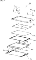
- FIG. 2 is an exploded perspective view of the chassis 20.
- the chassis 20 includes: covers 30 and 40; a holding member 50; and a display unit U.
- the holding member 50 and the display unit U are arranged within the covers 30 and 40.
- the covers 30 and 40 define the front surface 21 and the rear surface 22 of the chassis 20, respectively.
- the display unit U includes a touch panel TP and a display panel DP overlapping each other.
- the touch panel TP is arranged at the cover 30 side, whereas the display panel DP is arranged at the cover 40 side.
- the covers 30 and 40 are examples of first and second covers opposite to each other.
- the cover 30 has a frame shape in order to expose the touch panel TP and ensure visibility of the display panel DP.
- Sponges E1 are arranged between the cover 30 and the touch panel TP. Each of the sponges E1 linearly extends. The sponges E1 are attached to an inner side of the cover 30 with double-stick tapes or adhesive bonds. The sponges E1 are arranged along sides of the touch panel TP, respectively.
- the holding member 50 holds the touch panel TP.
- the holding member 50 is made of a synthetic resin.
- Sponges E2 are arranged between the display panel DP and the cover 40.
- the sponges E2 are different in shape from one another, but may be the same.
- the sponges E2 are attached to an inner side of the cover 40 by double-stick tapes or adhesive bonds.
- the sponge E2 is an example of an elastic member arranged between the display panel DP and the chassis 10.
- the sponge E2 is also an example of a foam member.
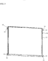
- FIG. 3 is an external view of the holding member 50.
- the holding member 50 is made of a synthetic resin.
- the holding member 50 includes: a base portion 52 having a frame shape; projection portions 54 extends to the outside of the base portion 52; and through holes 55 respectively formed at the projection portions 54.
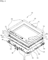
- FIG. 4 is an exploded perspective view of the chassis 20.
- plural recess portions 32 and 34 are formed in the cover 30.
- the recess portions 32 and 34 have through holes through which screws S penetrate, respectively.
- the screws S penetrate the through holes and threadedly engages threaded holes of the cover 40, respectively.
- the recess portions 32 and 34 are fitted with rubbers G for covering the screws S, respectively.
- the rubbers G are different in shape from each other to correspond to the shapes of the recess portions 32 and 34.
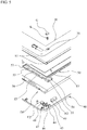
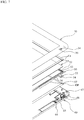
- FIGs. 5 to 7 are enlarged views of FIG. 4 .
- the cover 40 is provided with projection pieces 46 and 47 projecting from an inner surface of the cover 40 toward the cover 30 side.
- the projection pieces 46 and 47 are examples of positioning portions that abut side surfaces of the display panel DP and position the display panel DP in the planer direction thereof.
- the projection piece 46 abuts one of two opposed short sides of the display panel DP.
- the projection piece 47 abuts one of two opposed long sides of the display panel DP.
- the projection pieces 46 and 47 are respectively attached with sponges, and abut the display panel DP through the sponges.
- Other projection pieces 46 and 47 are provided at portions other than the position illustrated in FIGs. 5 to 7 .
- the cover 40 is also provided with support portions 42 and 44 projecting toward the cover 30 side.
- the support portions 42 and 44 are respectively formed with threaded holes 43 and 45.
- the recess portions 32 and 34 are respectively formed with through holes 33 and 35. At least one of plural screws S threadedly engages the threaded hole 43 formed in the support portion 42 of the cover 40 by penetrating through the through hole 33 formed in the recess portion 32. This secures the covers 30 and 40. Also, at least one of plural screws S threadedly engages the threaded hole 45 formed in the support portion 44 of the cover 40 by penetrating through the through holes 35 of the cover 30 and through hole 55 of the holding member 50. This couples the covers 30 and 40 and the holding member 50.
- the holding member 50 is provided at the base portion 52 with a projection portion 56 projecting toward the cover 30 side, a projection portion 57 projecting toward the cover 40, and a support portion 53 projecting toward an inner side of the holding member 50.
- the projection portion 56 is formed along an edge of the base portion 52.
- the projection portion 57 is partially formed along an edge of the base portion 52.
- a worker arranges the display panel DP on the sponges E2 attached on the cover 40 such that the display panel DP is positioned by the projection pieces 46 and 47 of the cover 40.
- the projection pieces 46 and 47 enables the display panel DP to be arranged easily at the desired position in the cover 40.
- the worker assembles the holding member 50 holding the touch panel TP into the display panel DP. Specifically, the worker causes the projection portion 57 of the holding member 50 to engage the display panel DP.
- the worker arranges the cover 30 attached with the sponges E1 to overlap the cover 40, and then secures the covers 30 and 40 and the holding member 50 by the screws S.
- the worker inserts the rubbers G into the recess portions 32 and 34, respectively.
- the chassis 20 is assembled in this way.
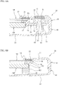
- FIGs. 8A and 8B are sectional views of the assembled chassis 20.
- FIG. 8A is a sectional view illustrating the projection portion 54 of the holding member 50.
- FIG. 8B is a sectional view illustrating the sponge E2.
- the projection portions 56 and 57 abut and engage the edges of the touch panel TP and the display panel DP, respectively.
- the projection portions 56 and 57 are examples of positioning portions that position the touch panel TP and the display panel DP.
- the support portion 53 is located between the touch panel TP and the display panel DP.
- the support portion 53 is an example of a spacer portion defining a clearance between the touch panel TP and the display panel DP.
- the touch panel TP is held by the holding member 50 by being supported by the support portion 53 thereof and engaging the projection portions 56 and 57.
- the screw S illustrated in FIG. 8A secures the covers 30 and 40, and the holding member 50 together.
- the screw S illustrated in FIG. 8A is an example of a common part securing the covers 30 and 40, and the holding member 50 together.
- the projection portion 54 of the holding member 50 is held so as to be sandwiched between the recess portions 34 of the cover 30 and the support member 44 of the cover 40. Therefore, the holding member 50 is positionally defined in the planar direction and the thickness direction of the chassis 20, and is secured thereto.
- the touch panel TP is held between the cover 30 and the holding member 50. Specifically, an end of the projection portion 56 and the touch panel TP are pushed to the sponge E1. This prevents dusts from entering a gap between the cover 30 and the touch panel TP.
- the sponge E2 is supported by a lib 49 slightly protruding from the inner side of the cover 40.
- the sponge E2 is deformed and crushed by the display panel DP.
- the holding member 50 pushes the display panel DP toward the sponge E2.
- the display panel DP is applied with a pressure force of the holding member 50 and an elastic repulsive force of the sponge E2 in a direction opposite to the pressure force. This prevents the display panel DP from chattering between the sponge E2 and the holding member 50.
- the holding member 50 pushes and secures the display panel DP to the cover 40 with holding the touch panel TP.
- FIG. 9 is an exploded perspective view of a chassis 20x having a structure different from the chassis 20 according to the present embodiment. Additionally, similar components of the chassis 20x as those of the chassis 20 are designated with similar reference numerals and a description of those components will be omitted.
- the chassis 20x includes two securing members 60x secured to a display panel DPx.
- the securing member 60x has a plate shape extending along an edge of the display panel DPx.
- the securing member 60x is made of metal.
- a holding member 50x is not provided with the through holes 55.
- a worker secures the securing members 60x to the display panel DPx, and then secures the securing members 60x to a cover 40x.
- the worker assembles the holding member 50 holding a touch panel TPx into the securing members 60x, and then secures a cover 30x to the cover 40x by screws Sx2.
- This assembles the chassis 20x.
- the holding member 50x is not provided with the through holes 55.
- the screws Sx2 secure the covers 30x and 40x to each other.
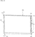
- FIG. 10 is an external view of the display panel DPx to which the securing members 60x are secured.
- the two securing members 60x are secured to the display panel DPx by the screws Sx.
- the securing member 60x is provided with projection portions 64x projecting to the outside of the display panel DPx.
- a through hole 65x is formed in the projection portion 64x.
- FIGs. 11 A and 11 B are sectional views of the chassis 20x having the structure different from the chassis 20 according to the present embodiment.
- the screw Sx1 threadedly engages a threaded hole 45x formed in a support portion 44x of the cover 40x by penetrating through a through hole 65x of the projection portion 64x, whereby the securing member 60x is secured to the cover 40x.
- the holding member 50x holds the touch panel TPx and engages the display panel DPx to which the securing member 60x is secured.
- the chassis 20x uses the holding member 50x for holding the touch panel TPx, and the securing members 60x for securing the display panel DPx to the cover 40x.
- the holding member 50 holds the touch panel TP and secures the display panel DP to the cover 40.
- the chassis 20 of the notebook computer 1 according to the present embodiment eliminates the securing members 60x. For this reason, the weight of the chassis 20 is reduced and the number of the assembling steps thereof is also reduced as compared with the chassis 20x.
- the worker has to secure the securing members 60x to the display panel DPx by the screws Sx, and then has to further secure the securing members 60x to the cover 40x by the screws Sx1.
- the worker has only to arrange the display panel DP on the cover 40,and then has only to securing the holding member 50 to the covers 30 and 40 by the screws S, thereby securing the display panel DP. For this reason, the number of screws used in the chassis 20 is reduced as compared with the chassis 20x.
- the chassis 20 has a light weight and an improved assembling property.
- the securing members 60x are secured to the cover 40x by the screws Sx1, and the covers 30x and 40x are secured to each other by the screws Sx2.
- the covers 30 and 40 and the holding member 50 are secured together by common screws S. For this reason, the number of screws used in the chassis 20 is reduced as compared with the chassis 20x.
- the chassis 20 has a light weight and an improved assembling property.
- the covers 30 and 40 and the holding member 50 may be secured together by a pin, instead of the screw S, capable of press fitting into holes that are respectively formed in the covers 30 and 40 and the holding member 50.
- a rubber or a spring may be used instead of the sponge E2.
- the spring may have a coil shape or a flat plate shape. Additionally, the use of the sponge E2 instead of a spring or a rubber achieves the reduced weight.
- the electronic device may be not limited to that.
- the electronic device may be a tablet computer, a mobile telephone, a mobile television, an electronic dictionary, a PDA, a gaming machine, a camera, a music player, or a navigation.
- the electronic device may be not only such a portable device but also a stationary electronic device.
- the electronic device may be a monitor used for a desktop computer, a monitor in which a computer is installed, a television, an audio, or another electrical appliance.
Landscapes
- Engineering & Computer Science (AREA)
- Computer Hardware Design (AREA)
- Theoretical Computer Science (AREA)
- Physics & Mathematics (AREA)
- Human Computer Interaction (AREA)
- General Engineering & Computer Science (AREA)
- General Physics & Mathematics (AREA)
- Mathematical Physics (AREA)
- Casings For Electric Apparatus (AREA)
- Position Input By Displaying (AREA)
- Devices For Indicating Variable Information By Combining Individual Elements (AREA)
Abstract
An electronic device includes: a chassis (10, 20); an input device (K, PD) and a display panel (U) that are arranged within the chassis; an elastic member (E2) that is arranged between the chassis and the display panel (U); and a holding member (50) that holds the input device, that is secured to the chassis, and that pushes the display panel toward the elastic member to deform the elastic member.
Description
- The present invention relates to an electronic device.
- There is known an electronic device equipped with a chassis, in which a touch panel and a display panel arranged. As an example of a method for securing the touch panel and the display panel to the chassis, a securing member is secured to the display panel and then secured to the chassis, and a holding member holding the touch panel is assembled into the display panel. The related art is disclosed in Japanese Laid-open Patent Publication Nos.
03-292523 09-115378 - Securing the touch panel and the display panel to the chassis needs both the holding member for holding the touch panel and the securing member for securing the display panel to the chassis. This may result in increased weight of the whole device.
- Accordingly, it is desirable to provide an electronic device having a reduced weight and provided with an input device and a display panel.
- According to an aspect of the embodiments, an electronic device includes: a chassis; an input device and a display panel that are arranged within the chassis; an elastic member that is arranged between the chassis and the display panel; and a holding member that holds the input device, that is secured to the chassis, and that pushes the display panel toward the elastic member to deform the elastic member.
- The advantages of the invention will be realized and attained by means of the elements and combinations particularly pointed out in the claims.
- It is to be understood that both the foregoing general description and the following detailed description are exemplary and explanatory and are not restrictive of the invention, as claimed.
- Reference is made, by way of example only, to the accompanying drawings in which:
-
FIGs. 1A to 1C are explanatory views of a notebook computer according to a present embodiment; -
FIG. 2 is an exploded perspective view of a chassis; -
FIG. 3 is an external view of a holding member; -
FIG. 4 is an exploded perspective view of the chassis; -
FIG. 5 is an enlarged view ofFIG. 4 ; -
FIG. 6 is an enlarged view ofFIG. 4 ; -
FIG. 7 is an enlarged view ofFIG. 4 ; -
FIGs. 8A and 8B are sectional views of the assembled chassis; -
FIG. 9 is an exploded perspective view of a chassis having a structure different from the chassis according to the present embodiment; -
FIG. 10 is an external view of a display panel to which securing members are secured; and -
FIGs. 11A and 11B are sectional views of the chassis having the structure different from the chassis according to the present embodiment. - A description will be given of an exemplary notebook computer as an electronic device.
FIGs. 1A to 1C are explanatory views of anotebook computer 1 according to the present embodiment. Thenotebook computer 1 has achassis chassis chassis 10 includes atop surface 11 and a bottom surface opposite to thetop surface 11. A keyboard K and a touch pad PD for operating thenotebook computer 1 are provided on thetop surface 11. A motherboard for controlling the whole operation of thenotebook computer 1 is housed in thechassis 10. Thechassis 20 includes afront surface 21 and arear surface 22 opposite to thefront surface 21. A display unit U is provided on thefront surface 21. The display unit U includes: a display panel capable of displaying images; and an operable touch panel by touching the touch panel. Additionally, the touch panel may adopt various types such as a resistive type, a surface elastic wave type, and an infrared type. Further, the touch panel may adopt a capacitive type using a variation of a capacitance between a user's fingertip and a conductive layer without using a touch pen. Furthermore, the touch panel may adopt an electromagnetic induction pen tablet using an electronic pen instead of a touch panel. These touch panels and the pen tablet are examples of the input device. The two-axis hinge H couples thechassis top surface 11 extends. The central axis A2 virtually extends in the direction intersecting thetop surface 11. That is, the central axes A1 and A2 are intersected with each other. -
FIG. 1A illustrates a first folded state where thefront surface 21 of thechassis 20 overlaps thetop surface 11 of thechassis 10.FIG. 1B illustrates an opened state where thechassis FIG. 1C illustrates a second folded state where therear surface 22 of thechassis 20 overlaps thetop surface 11 of thechassis 10. A user rotates thechassis 20 about the central axis A1 from the first folded state, whereby thenotebook computer 1 is in the opened state. The user rotates thechassis 20 about the central axis A2 from the opened state illustrated inFIG. 1B , whereby thefront surface 21 and therear surface 22 of thechassis 20 are reversed from the state illustrated inFIG 1B . The user rotates thechassis 20 about the central axis A1 to overlap thechassis 10 with thefront surface 21 and therear surface 22 of thechassis 20 reversed. This enables thenotebook computer 1 to be in the second folded state where thetop surface 11 of thechassis 10 faces therear surface 22 of thechassis 20. -
FIG. 2 is an exploded perspective view of thechassis 20. Thechassis 20 includes: covers 30 and 40; aholding member 50; and a display unit U. Theholding member 50 and the display unit U are arranged within thecovers covers front surface 21 and therear surface 22 of thechassis 20, respectively. The display unit U includes a touch panel TP and a display panel DP overlapping each other. The touch panel TP is arranged at thecover 30 side, whereas the display panel DP is arranged at thecover 40 side. The covers 30 and 40 are examples of first and second covers opposite to each other. Thecover 30 has a frame shape in order to expose the touch panel TP and ensure visibility of the display panel DP. Sponges E1 are arranged between thecover 30 and the touch panel TP. Each of the sponges E1 linearly extends. The sponges E1 are attached to an inner side of thecover 30 with double-stick tapes or adhesive bonds. The sponges E1 are arranged along sides of the touch panel TP, respectively. - The holding
member 50 holds the touch panel TP. The holdingmember 50 is made of a synthetic resin. Sponges E2 are arranged between the display panel DP and thecover 40. The sponges E2 are different in shape from one another, but may be the same. The sponges E2 are attached to an inner side of thecover 40 by double-stick tapes or adhesive bonds. The sponge E2 is an example of an elastic member arranged between the display panel DP and thechassis 10. The sponge E2 is also an example of a foam member. -
FIG. 3 is an external view of the holdingmember 50. The holdingmember 50 is made of a synthetic resin. The holdingmember 50 includes: abase portion 52 having a frame shape;projection portions 54 extends to the outside of thebase portion 52; and throughholes 55 respectively formed at theprojection portions 54. -
FIG. 4 is an exploded perspective view of thechassis 20. As illustrated inFIG. 4 ,plural recess portions cover 30. Therecess portions cover 40, respectively. Therecess portions recess portions -
FIGs. 5 to 7 are enlarged views ofFIG. 4 . As illustrated inFIG. 4 , thecover 40 is provided withprojection pieces cover 40 toward thecover 30 side. Theprojection pieces projection piece 46 abuts one of two opposed short sides of the display panel DP. Theprojection piece 47 abuts one of two opposed long sides of the display panel DP. Additionally, theprojection pieces Other projection pieces FIGs. 5 to 7 . Thecover 40 is also provided withsupport portions cover 30 side. Thesupport portions holes - The
recess portions holes hole 43 formed in thesupport portion 42 of thecover 40 by penetrating through the throughhole 33 formed in therecess portion 32. This secures thecovers hole 45 formed in thesupport portion 44 of thecover 40 by penetrating through the throughholes 35 of thecover 30 and throughhole 55 of the holdingmember 50. This couples thecovers member 50. The holdingmember 50 is provided at thebase portion 52 with aprojection portion 56 projecting toward thecover 30 side, aprojection portion 57 projecting toward thecover 40, and asupport portion 53 projecting toward an inner side of the holdingmember 50. Theprojection portion 56 is formed along an edge of thebase portion 52. Theprojection portion 57 is partially formed along an edge of thebase portion 52. - A description will be given of an assembling order of the
chassis 20. A worker arranges the display panel DP on the sponges E2 attached on thecover 40 such that the display panel DP is positioned by theprojection pieces cover 40. Theprojection pieces cover 40. Next, the worker assembles the holdingmember 50 holding the touch panel TP into the display panel DP. Specifically, the worker causes theprojection portion 57 of the holdingmember 50 to engage the display panel DP. Next, the worker arranges thecover 30 attached with the sponges E1 to overlap thecover 40, and then secures thecovers member 50 by the screws S. Next, the worker inserts the rubbers G into therecess portions chassis 20 is assembled in this way. -
FIGs. 8A and 8B are sectional views of the assembledchassis 20.FIG. 8A is a sectional view illustrating theprojection portion 54 of the holdingmember 50.FIG. 8B is a sectional view illustrating the sponge E2. Referring toFIGs. 8A and 8B , theprojection portions projection portions support portion 53 is located between the touch panel TP and the display panel DP. Thesupport portion 53 is an example of a spacer portion defining a clearance between the touch panel TP and the display panel DP. The touch panel TP is held by the holdingmember 50 by being supported by thesupport portion 53 thereof and engaging theprojection portions - The screw S illustrated in
FIG. 8A secures thecovers member 50 together. The screw S illustrated inFIG. 8A is an example of a common part securing thecovers member 50 together. Theprojection portion 54 of the holdingmember 50 is held so as to be sandwiched between therecess portions 34 of thecover 30 and thesupport member 44 of thecover 40. Therefore, the holdingmember 50 is positionally defined in the planar direction and the thickness direction of thechassis 20, and is secured thereto. - As illustrated in
FIG. 8A , the touch panel TP is held between thecover 30 and the holdingmember 50. Specifically, an end of theprojection portion 56 and the touch panel TP are pushed to the sponge E1. This prevents dusts from entering a gap between thecover 30 and the touch panel TP. - As illustrated in
FIG. 8B , the sponge E2 is supported by alib 49 slightly protruding from the inner side of thecover 40. The sponge E2 is deformed and crushed by the display panel DP. This is because the holdingmember 50 pushes the display panel DP toward the sponge E2. Thus, the display panel DP is applied with a pressure force of the holdingmember 50 and an elastic repulsive force of the sponge E2 in a direction opposite to the pressure force. This prevents the display panel DP from chattering between the sponge E2 and the holdingmember 50. As mentioned above, the holdingmember 50 pushes and secures the display panel DP to thecover 40 with holding the touch panel TP. -
FIG. 9 is an exploded perspective view of achassis 20x having a structure different from thechassis 20 according to the present embodiment. Additionally, similar components of thechassis 20x as those of thechassis 20 are designated with similar reference numerals and a description of those components will be omitted. Thechassis 20x includes two securingmembers 60x secured to a display panel DPx. The securingmember 60x has a plate shape extending along an edge of the display panel DPx. The securingmember 60x is made of metal. Unlike the holdingmember 50, a holdingmember 50x is not provided with the through holes 55. - A description will be given of an assembling order of the
chassis 20x. A worker secures the securingmembers 60x to the display panel DPx, and then secures the securingmembers 60x to acover 40x. Next, the worker assembles the holdingmember 50 holding a touch panel TPx into the securingmembers 60x, and then secures acover 30x to thecover 40x by screws Sx2. This assembles thechassis 20x. As mentioned above, unlike the holdingmember 50, the holdingmember 50x is not provided with the through holes 55. Thus, the screws Sx2 secure thecovers -
FIG. 10 is an external view of the display panel DPx to which the securingmembers 60x are secured. The two securingmembers 60x are secured to the display panel DPx by the screws Sx. The securingmember 60x is provided withprojection portions 64x projecting to the outside of the display panel DPx. A throughhole 65x is formed in theprojection portion 64x. -
FIGs. 11 A and 11 B are sectional views of thechassis 20x having the structure different from thechassis 20 according to the present embodiment. As illustrated inFIG. 11A , the screw Sx1 threadedly engages a threadedhole 45x formed in asupport portion 44x of thecover 40x by penetrating through a throughhole 65x of theprojection portion 64x, whereby the securingmember 60x is secured to thecover 40x. As illustrated inFIG. 11B , the holdingmember 50x holds the touch panel TPx and engages the display panel DPx to which the securingmember 60x is secured. In this manner, thechassis 20x uses the holdingmember 50x for holding the touch panel TPx, and the securingmembers 60x for securing the display panel DPx to thecover 40x. - In the
chassis 20 of thenotebook computer 1 according to the present embodiment, the holdingmember 50 holds the touch panel TP and secures the display panel DP to thecover 40. Thus, thechassis 20 of thenotebook computer 1 according to the present embodiment eliminates the securingmembers 60x. For this reason, the weight of thechassis 20 is reduced and the number of the assembling steps thereof is also reduced as compared with thechassis 20x. - As for the
chassis 20x, the worker has to secure the securingmembers 60x to the display panel DPx by the screws Sx, and then has to further secure the securingmembers 60x to thecover 40x by the screws Sx1. As for thechassis 20 according to the present embodiment, the worker has only to arrange the display panel DP on thecover 40,and then has only to securing the holdingmember 50 to thecovers chassis 20 is reduced as compared with thechassis 20x. Thus, thechassis 20 has a light weight and an improved assembling property. - In the
chassis 20x, the securingmembers 60x are secured to thecover 40x by the screws Sx1, and thecovers chassis 20 according to the present embodiment, thecovers member 50 are secured together by common screws S. For this reason, the number of screws used in thechassis 20 is reduced as compared with thechassis 20x. Thus, thechassis 20 has a light weight and an improved assembling property. Additionally, thecovers member 50 may be secured together by a pin, instead of the screw S, capable of press fitting into holes that are respectively formed in thecovers member 50. - A rubber or a spring may be used instead of the sponge E2. The spring may have a coil shape or a flat plate shape. Additionally, the use of the sponge E2 instead of a spring or a rubber achieves the reduced weight.
- The above embodiment has described the notebook computer as an example of the electronic device. However, the electronic device may be not limited to that. For example, the electronic device may be a tablet computer, a mobile telephone, a mobile television, an electronic dictionary, a PDA, a gaming machine, a camera, a music player, or a navigation. Also, the electronic device may be not only such a portable device but also a stationary electronic device. For example, the electronic device may be a monitor used for a desktop computer, a monitor in which a computer is installed, a television, an audio, or another electrical appliance.
- All examples and conditional language recited herein are intended for pedagogical purposes to aid the reader in understanding the invention and the concepts contributed by the inventor to furthering the art, and are to be constructed as being without limitation to such specifically recited examples and conditions, nor does the organization of such examples in the specification relate to a showing of the superiority and inferiority of the invention. Although the embodiment of the present inventions has been described in detail, it should be understood that the various changes, substitutions, and alterations could be made hereto without departing from the scope of the claims.
Claims (6)
- An electronic device comprising:a chassis;an input device and a display panel that are arranged within the chassis;an elastic member that is arranged between the chassis and the display panel; anda holding member that holds the input device, that is secured to the chassis, and that pushes the display panel toward the elastic member to deform the elastic member.
- The electronic device of claim 1, wherein
the chassis comprises first and second covers that are opposite to each other, and
the first cover, the second cover, and the holding member are secured together by a common part. - The electronic device of claim 1 or 2, wherein the chassis comprises a positioning portion that positions the display panel in a plane direction of the display panel.
- The electronic device of any one of claims 1 to 3, wherein
the holding member comprises:a positioning portion that positions the input device and the display panel in a plane direction of the display panel; anda spacer portion that defines a clearance between the input device and the display panel. - The electronic device of any one of claims 1 to 4, wherein the elastic member comprises at least one of a foam member, a rubber, and a spring.
- The electronic device of any one of claims 1 to 5, wherein the input device is a touch panel.
Applications Claiming Priority (1)
| Application Number | Priority Date | Filing Date | Title |
|---|---|---|---|
| JP2011076339A JP5724535B2 (en) | 2011-03-30 | 2011-03-30 | Electronic equipment |
Publications (1)
| Publication Number | Publication Date |
|---|---|
| EP2508959A1 true EP2508959A1 (en) | 2012-10-10 |
Family
ID=45540819
Family Applications (1)
| Application Number | Title | Priority Date | Filing Date |
|---|---|---|---|
| EP12152773A Withdrawn EP2508959A1 (en) | 2011-03-30 | 2012-01-26 | Electronic device |
Country Status (3)
| Country | Link |
|---|---|
| US (1) | US8896994B2 (en) |
| EP (1) | EP2508959A1 (en) |
| JP (1) | JP5724535B2 (en) |
Families Citing this family (15)
| Publication number | Priority date | Publication date | Assignee | Title |
|---|---|---|---|---|
| US8776358B2 (en) * | 2007-08-06 | 2014-07-15 | Apple Inc. | Housing components for electronic devices |
| TW201311101A (en) * | 2011-08-22 | 2013-03-01 | Wistron Corp | Portable electronic module with back cover changing function |
| JP5754466B2 (en) * | 2013-01-30 | 2015-07-29 | 株式会社デンソー | Display device |
| CN103342068B (en) * | 2013-06-25 | 2015-07-15 | 谢虹 | Fluorescent screen |
| US9383768B1 (en) * | 2014-03-28 | 2016-07-05 | Amazon Technologies, Inc. | Compressive and elastic bonding component of an electronic device |
| TWM493130U (en) * | 2014-06-11 | 2015-01-01 | Innolux Corp | Display device |
| JP6129885B2 (en) * | 2015-02-04 | 2017-05-17 | Necパーソナルコンピュータ株式会社 | Information processing device |
| EP3073810B1 (en) * | 2015-03-26 | 2021-10-06 | Vitesco Technologies GmbH | Electronic control unit with a housing stabilizing element and housing for electronic control unit |
| CN104834399B (en) * | 2015-04-15 | 2018-06-22 | 业成光电(深圳)有限公司 | Touch-control display module |
| JP6699572B2 (en) * | 2017-01-27 | 2020-05-27 | ブラザー工業株式会社 | Display device and machine tool |
| TWI680327B (en) * | 2018-10-16 | 2019-12-21 | 佳世達科技股份有限公司 | Display device |
| JP7376986B2 (en) * | 2018-11-06 | 2023-11-09 | シャープ株式会社 | Electronics |
| JP6620961B1 (en) * | 2019-01-17 | 2019-12-18 | 富士通クライアントコンピューティング株式会社 | Electronics |
| EP4336807B1 (en) | 2021-11-24 | 2025-10-29 | Samsung Electronics Co., Ltd. | Electronic apparatus including protective cover for protecting flexible display |
| EP4697132A1 (en) * | 2023-07-07 | 2026-02-18 | Samsung Electronics Co., Ltd. | Housing and electronic device comprising same |
Citations (7)
| Publication number | Priority date | Publication date | Assignee | Title |
|---|---|---|---|---|
| JPH03292523A (en) | 1990-04-11 | 1991-12-24 | Fujitsu Ltd | Attachment frame for touch panel |
| JPH09115378A (en) | 1995-10-23 | 1997-05-02 | Fujitsu Kiden Ltd | Mounting structure for touch switch type liquid crystal display panel |
| EP1150199A2 (en) * | 2000-04-19 | 2001-10-31 | Nec Corporation | Display device and information terminal apparatus |
| US20030223187A1 (en) * | 2002-06-04 | 2003-12-04 | Johnson Tsao | Portable computer which uses spring to buffer shock force of a monitor |
| EP1591870A2 (en) * | 2004-04-27 | 2005-11-02 | Siemens Aktiengesellschaft | Supporting element and arrangement for supporting a display against a casing |
| US20050285990A1 (en) * | 2004-06-25 | 2005-12-29 | Havelka Steven E | Non-ruggedized COTS display packaging for severe environment applications |
| US20060012578A1 (en) * | 2004-07-14 | 2006-01-19 | Fujitsu Limited | Panel unit capable of avoiding contact between electrically conductive bodies thereon |
Family Cites Families (13)
| Publication number | Priority date | Publication date | Assignee | Title |
|---|---|---|---|---|
| JPH06230873A (en) * | 1993-02-03 | 1994-08-19 | Seiko Epson Corp | Small information device |
| US5363276A (en) * | 1993-09-01 | 1994-11-08 | Ncr Corporation | Apparatus for containing and supporting electronic components |
| US5579036A (en) * | 1994-04-28 | 1996-11-26 | At&T Global Information Solutions Company | Touch screen device and shielding bracket therefor |
| JPH09114590A (en) * | 1995-10-18 | 1997-05-02 | Seiko Epson Corp | Liquid crystal device with input function and electronic equipment using the same |
| JPH1027066A (en) * | 1996-07-12 | 1998-01-27 | Toshiba Corp | Input display device and portable electronic device having the same |
| US5887837A (en) * | 1996-09-30 | 1999-03-30 | Johns; H. Douglas | Pivotal computer stand |
| US6532152B1 (en) * | 1998-11-16 | 2003-03-11 | Intermec Ip Corp. | Ruggedized hand held computer |
| JP3538046B2 (en) * | 1998-12-11 | 2004-06-14 | Nec液晶テクノロジー株式会社 | Portable terminal device |
| JP2001311937A (en) * | 2000-04-28 | 2001-11-09 | Pentel Corp | Liquid crystal display integrated input device |
| US6897852B2 (en) * | 2002-03-28 | 2005-05-24 | Symbol Technologies, Inc. | Information input display device |
| JP4172293B2 (en) * | 2003-02-28 | 2008-10-29 | 住友電装株式会社 | Display device |
| JP4528590B2 (en) * | 2004-09-28 | 2010-08-18 | 株式会社東芝 | Electronics |
| JP5073068B2 (en) * | 2011-02-14 | 2012-11-14 | 株式会社東芝 | Electronics |
-
2011
- 2011-03-30 JP JP2011076339A patent/JP5724535B2/en not_active Expired - Fee Related
- 2011-11-16 US US13/297,848 patent/US8896994B2/en not_active Expired - Fee Related
-
2012
- 2012-01-26 EP EP12152773A patent/EP2508959A1/en not_active Withdrawn
Patent Citations (7)
| Publication number | Priority date | Publication date | Assignee | Title |
|---|---|---|---|---|
| JPH03292523A (en) | 1990-04-11 | 1991-12-24 | Fujitsu Ltd | Attachment frame for touch panel |
| JPH09115378A (en) | 1995-10-23 | 1997-05-02 | Fujitsu Kiden Ltd | Mounting structure for touch switch type liquid crystal display panel |
| EP1150199A2 (en) * | 2000-04-19 | 2001-10-31 | Nec Corporation | Display device and information terminal apparatus |
| US20030223187A1 (en) * | 2002-06-04 | 2003-12-04 | Johnson Tsao | Portable computer which uses spring to buffer shock force of a monitor |
| EP1591870A2 (en) * | 2004-04-27 | 2005-11-02 | Siemens Aktiengesellschaft | Supporting element and arrangement for supporting a display against a casing |
| US20050285990A1 (en) * | 2004-06-25 | 2005-12-29 | Havelka Steven E | Non-ruggedized COTS display packaging for severe environment applications |
| US20060012578A1 (en) * | 2004-07-14 | 2006-01-19 | Fujitsu Limited | Panel unit capable of avoiding contact between electrically conductive bodies thereon |
Also Published As
| Publication number | Publication date |
|---|---|
| US20120250284A1 (en) | 2012-10-04 |
| US8896994B2 (en) | 2014-11-25 |
| JP2012212220A (en) | 2012-11-01 |
| JP5724535B2 (en) | 2015-05-27 |
Similar Documents
| Publication | Publication Date | Title |
|---|---|---|
| EP2508959A1 (en) | Electronic device | |
| JP6683753B2 (en) | Touch module and electronic calculator having touch module | |
| US10725567B1 (en) | Touchpad module and computing device using same | |
| US9268371B2 (en) | Hinge module and electronic device using the same | |
| JP2014085941A (en) | Electronic apparatus | |
| CN103197786B (en) | Thin touch control panel module and assembling method thereof | |
| KR20160061180A (en) | Electronic device | |
| US10606377B1 (en) | Touchpad module and computing device using same | |
| US11556189B1 (en) | Touchpad module and computing device using same | |
| US10921865B2 (en) | Input touchpad module and computing device having a touch member with improved swinging stability | |
| US11726584B1 (en) | Touchpad module and computing device using same | |
| US20140321043A1 (en) | Supporting structure and electronic device using the same | |
| TW201251589A (en) | Touchpad assembly and electronic apparatus using the same | |
| US20190385800A1 (en) | Touch module | |
| JP2010009387A (en) | Assembly and electronic apparatus | |
| US20210263610A1 (en) | Touchpad module and computing device using same | |
| US11556155B2 (en) | Touchpad module and computing device using same | |
| US10510499B1 (en) | SMD switch and touchpad module and computing device using same | |
| JP6322908B2 (en) | Display device and display support device | |
| JP7557583B1 (en) | Touchpad | |
| US10643806B1 (en) | Touchpad module and computing device using same | |
| US9870883B2 (en) | Input device and electronic equipment | |
| US20120243161A1 (en) | Electronic device | |
| US11093009B2 (en) | Movalbe input device in a computer casing | |
| CN108874183A (en) | Mouse (Saggar) |
Legal Events
| Date | Code | Title | Description |
|---|---|---|---|
| PUAI | Public reference made under article 153(3) epc to a published international application that has entered the european phase |
Free format text: ORIGINAL CODE: 0009012 |
|
| AK | Designated contracting states |
Kind code of ref document: A1 Designated state(s): AL AT BE BG CH CY CZ DE DK EE ES FI FR GB GR HR HU IE IS IT LI LT LU LV MC MK MT NL NO PL PT RO RS SE SI SK SM TR |
|
| AX | Request for extension of the european patent |
Extension state: BA ME |
|
| 17P | Request for examination filed |
Effective date: 20130404 |
|
| 17Q | First examination report despatched |
Effective date: 20150803 |
|
| STAA | Information on the status of an ep patent application or granted ep patent |
Free format text: STATUS: THE APPLICATION IS DEEMED TO BE WITHDRAWN |
|
| 18D | Application deemed to be withdrawn |
Effective date: 20151215 |