EP2508881A1 - Testing a humidity sensor - Google Patents
Testing a humidity sensor Download PDFInfo
- Publication number
- EP2508881A1 EP2508881A1 EP11002800A EP11002800A EP2508881A1 EP 2508881 A1 EP2508881 A1 EP 2508881A1 EP 11002800 A EP11002800 A EP 11002800A EP 11002800 A EP11002800 A EP 11002800A EP 2508881 A1 EP2508881 A1 EP 2508881A1
- Authority
- EP
- European Patent Office
- Prior art keywords
- temperature
- humidity
- value
- denotes
- relative humidity
- Prior art date
- Legal status (The legal status is an assumption and is not a legal conclusion. Google has not performed a legal analysis and makes no representation as to the accuracy of the status listed.)
- Granted
Links
Images


Classifications
-
- G—PHYSICS
- G01—MEASURING; TESTING
- G01N—INVESTIGATING OR ANALYSING MATERIALS BY DETERMINING THEIR CHEMICAL OR PHYSICAL PROPERTIES
- G01N27/00—Investigating or analysing materials by the use of electric, electrochemical, or magnetic means
- G01N27/02—Investigating or analysing materials by the use of electric, electrochemical, or magnetic means by investigating impedance
- G01N27/22—Investigating or analysing materials by the use of electric, electrochemical, or magnetic means by investigating impedance by investigating capacitance
- G01N27/223—Investigating or analysing materials by the use of electric, electrochemical, or magnetic means by investigating impedance by investigating capacitance for determining moisture content, e.g. humidity
Definitions
- the invention relates to a method for testing a humidity sensor, a corresponding computer program element, and to an arrangement for testing a humidity sensor.
- Humidity sensors are used in many different applications. What is common to nearly all the applications is that for the reason that the relative humidity in the environment of the sensor shall be detected, a sensitive element of such humidity sensor needs to be exposed to the environment for allowing sufficient access of the medium / the air containing the humidity to such sensitive element. However, the environment may contain chemical substances affecting the capability of the sensitive element to absorb humidity as required for precise measurements.
- a humidity sensor is disclosed with interdigital electrodes being arranged on a substrate.
- a sensitive layer for example a polymer layer, is deposited on the substrate and covers the electrodes.
- the polymer layer is susceptible to humidity. Humidity absorbed by the polymer layer changes the dielectric constant of the polymer layer such that a capacity between the electrodes represents a measure for the relative humidity of the environment.
- the problem to be solved by the present invention is therefore to provide a test for a humidity sensor which test allows for a conclusion if the humidity sensor is impaired in its capabilities of measuring humidity.
- a relative humidity is measured by the humidity sensor twice at different temperatures. For both measurements, corresponding values are calculated. These values are then evaluated. The evaluation result allows for a conclusion if the humidity sensor may be impaired in its capabilities of measuring humidity.
- the present idea makes use of the characteristics of a saturated vapour pressure at the different temperatures measured.
- One preferred way is to determine a dew point for each measurement, a formula for such dew point being dependent on the measured relative humidity and the saturated vapour pressure at the measured temperature.
- Another preferred way is to determine an absolute humidity for each measurement, a formula for such absolute humidity being dependent on the measured relative humidity and the saturated vapour pressure at the measured temperature.
- the following section may provide a reasoning why the above method may support the detection of impaired humidity sensors.
- the dew point denotes a temperature to which air needs to be cooled down in order to make vapour inherent in the air change its state into liquid water. This means that the dew point typically denotes a temperature below the current temperature. However, when the dew point is equal to the current temperature, the air is fully saturated by humidity.
- the relative humidity which can be measured by appropriate humidity sensors denotes the ratio of a current saturation of air with humidity relative to a maximum saturation of air with humidity.
- the relative humidity is dependent on the temperature. When the temperature increases, the capability of air to absorb additional humidity increases. However, this results in a decrease of the relative humidity since the current saturation of the air now is put into relation with a maximum saturation that is higher than before. As a result, with rising temperatures the relative humidity decreases, while with temperatures dropping the relative humidity rises.
- Formulas for calculating the dew point are dependent on the temperature and the relative humidity at such temperature.
- the relative humidity itself is dependent on the temperature.
- the relative humidity changes into the opposite direction.
- any change in the temperature shall be irrelevant. Irrespective of the temperature, the dew point remains constant since it denotes the temperature to which the temperature needs to be cooled down for effecting a phase transformation from vapour to water.
- the relative humidity measured may no longer correspond to the real relative humidity in the air.
- the correlation between the temperature and the relative humidity measured may be modified compared to an unaffected humidity sensor. From a bare measuring of the relative humidity one would not become aware of the impairment of the humidity sensor.
- the calculated dew point or any other value dependent on the saturated vapour pressure at the measured temperature and the associated measured relative humidity may be an appropriate indicator for a humidity sensor being affected in its sensing capabilities: Whenever for different temperatures the dew point - or more generally the value determined subject to the measured temperature and the associated measured relative humidity - no longer remains constant but varies, the conclusion may be that the sensing capability of the humidity sensor is affected. In particular, when the dew point calculated for a first relative humidity measured at a first temperature is different from the dew point calculated for a second relative humidity measured at a second temperature, then the humidity sensor may be detected as an affected humidity sensor and may need to be cleaned or replaced, for example.
- the present idea is based on the insight that although the relative humidity output by a humidity sensor changes with varying temperature, associated values such as the dew point or the absolute humidity which are calculated based on the measured relative humidity and the temperature do not change for varying temperatures. In case the dew point or another such value changes, this can be taken as an indicator that the humidity sensor is affected and its signal no longer reflects the real relative humidity of the environment.
- Varying the temperature of an air volume for which the humidity shall be measured may not be easy to achieve for test purposes.
- the humidity sensor itself may be subjected to a varying temperature. Heating or cooling the humidity sensor itself may be an appropriate means for the present testing.
- the temperature of the humidity sensor is measured.
- the temperature sensor is arranged close to the humidity sensor such that the temperature sensor substantially senses the temperature of the humidity sensor itself.
- the humidity sensor is integrated on a substrate, it is preferred to integrate the temperature sensor on this substrate, too. Given that the substrate may have a good thermal conductivity, an arrangement of the heater and the temperature sensor in close vicinity to the humidity sensor on the substrate may provide measuring results substantially representing the temperature of the humidity sensor or at least a strong dependency from such temperature.
- a computer program element which may be used in testing a humidity sensor.
- the computer program element comprises computer program code means for calculating a first value based on a first temperature and a first relative humidity measured by a humidity sensor at the first temperature, calculating a second value based on a second temperature and a second relative humidity measured by the humidity sensor at the second temperature, and comparing the first value with the second value.
- the first value is based on a saturated vapour pressure at the first temperature
- the second value is based on a saturated vapour pressure at the second temperature.
- an arrangement for testing a humidity sensor comprises the humidity sensor, a temperature sensor, and one of a heater and a cooler.
- a control unit is adapted for calculating a first value based on a first relative humidity measured by the humidity sensor at a first temperature and based on a saturated vapour pressure at the first temperature which first temperature is measured by the temperature sensor.
- the control unit is further adapted for calculating a second value based on a second relative humidity measured by the humidity sensor at a second temperature and based on a saturated vapour pressure at the second temperature. which second temperature is measured by the temperature sensor.
- the control unit is further adapted for comparing the first value with the second value.
- Figure 1 illustrates a longitudinal cut through a schematic testing arrangement for testing a humidity sensor according to an embodiment of the present invention.
- the humidity sensor 1 comprises a substrate 11, electrodes 13 arranged on or integrated into the substrate 11, and a humidity sensitive layer 12 arranged on the substrate 11 covering the electrodes 13.
- the sensitive layer 12 preferably is a polymer layer or a ceramic layer and is susceptible to humidity.
- a change in a dielectric constant of the sensitive layer 12 results in a change of a capacitance of the sensitive layer 12.
- the electrodes 13 are arranged as planar interdigital electrodes for measuring the capacitance of the sensitive layer 12 by means of an electric field indicated by reference numeral 14 penetrating the sensitive layer 12.
- a signal provided by the electrodes 13 may be taken as a measure for the relative amount of water molecules being absorbed in the sensitive layer 12 reflecting the relative humidity of the air surrounding the test arrangement.
- a heater 3 in form of a resistance heater and a temperature sensor 2 are arranged on the same substrate 11 next to the humidity sensor 1.
- the heater 3 is arranged such that when activated it allows for heating the humidity sensor 1.
- the temperature sensor 2 is arranged such that it allows for substantially measuring the temperature of the humidity sensor 1.
- the heater 3 and the temperature sensor 2 are arranged close to the humidity sensor 1, in a preferred embodiment within a radius of 5mm from the humidity sensor 1, and, in another preferred embodiment, the humidity sensor 1, the temperature sensor 2 and the heater 3 are arranged on the common substrate 11.
- the heater 3 and the temperature sensor 2 will be used during the testing routine as will be explained later on.
- a control unit 4 is schematically illustrated in Figure 1 as being integrated into the substrate 11 which substrate 11 may preferably be a semiconductor substrate.
- the control unit 4 may be adapted for testing the humidity sensor 1.
- the control unit 4 is connected to the humidity sensor 1, the temperature sensor 2, and the heater 3. It is envisaged that the control unit 4 may receive signals indicative of the relative humidity from the humidity sensor 1.
- additional circuitry may be implemented on the substrate 11, such as an A/D converter, or circuitry with other functionality.
- the control unit 4 may also receive signals indicative of the current temperature from the temperature sensor 2.
- the control unit 4 may also be adapted for activating and deactivating the heater 3 when needed.
- the control unit 4 may be adapted for automatically performing a value determination as explained later on and for initiating associated heating and/or cooling actions and/or measurements such that the control unit may perform a built-in self test of the humidity sensor.
- the relative humidity output by a humidity sensor changes when the temperature is varied - taking a certain delay time into account -, values based on the saturated vapour pressure at the subject temperature and based on the subject relative humidity are expected to remain constant.
- a tolerance for a value such as the dew point or the absolute humidity may be set.
- an allowed tolerance for such dew point may be at some temperature between 0.5° Celsius and 1° Celsius. Any such tolerance may be set subject to the temperature measured. Whenever the calculated value is rising or falling outside the accepted tolerance after a change in temperature, the humidity sensor can be expected to provide false relative humidity values.
- the above formula for the saturated vapour pressure is also known as Magnus formula.
- the constant m is set to 17.62
- the constant T n is set to 243.12° Celsius
- the constant ⁇ is set to 6.112 hPa.
- the relative humidity ⁇ is measured by the humidity sensor, for example the humidity sensor 1 of Figure 1 .
- the temperature T for which the humidity sensor 1 provides the associated relative humidity ⁇ is measured by the temperature sensor 2. It is noted that the measurements of the temperature T and the associated relative humidity ⁇ advantageously are performed within a time interval in which it can be expected that the temperature T does not change.
- a first relative humidity ⁇ 1 is measured as is the corresponding first temperature T1.
- the humidity sensor temperature T is modified and as a result the temperature T of the air volume in the close vicinity of the humidity sensor 1 becomes modified, too.
- the temperature T of the humidity sensor 1 is increased by means of the heater 3 of Figure 1 .
- the current humidity sensor temperature is measured as second temperature T2, as is the associated second relative humidity ⁇ 2.
- the measurements of the temperature T and the associated relative humidity ⁇ are performed in a time interval in which it can be expected that the temperature does not change.
- Figure 2 shows a diagram illustrating two dew point characteristics over temperature T.
- the first dew point characteristic is represented by the two lower dew points F1' and F2' and is based on measurements accomplished with a properly working humidity sensor.
- the second dew point characteristic is represented by two upper dew points F1''and F2'' and is based on measurements accomplished with an impaired humidity sensor.
- a deviation between the dew points F''2 and F''1 is two degrees Celsius which is above a sample threshold TH of one degree Celsius which may, in the present embodiment, represent the critical threshold TH for differentiating between a properly working humidity sensor and an impaired humidity sensor.
- the dew points themselves were evaluated as critical values for determining if the underlying humidity sensor is impaired, in another preferred embodiment, it generally is value V1 and value V2 being analyzed e.g. by means of forming a deviation
- such values V1, V2 may represent the absolute humidity AH1, AH2.
- Figure 3 illustrates a relationship between the dew point F in degrees Celsius, the relative humidity RH in % and the absolute humidity AH in g/m 3 in form of a diagram including various characteristics for various relative humidity values RH.
- the absolute humidity AH can be determined by using a diagram such as shown in Figure 4 .
- the information contained in such diagram may preferably be electronically stored in the test arrangement in form of a look up table within the control unit 4.
- the absolute humidity AH can be determined from such look-table.
- Determining the absolute humidity AH as the relevant value V to be evaluated finally results in two absolute humidity values AH1 and AH2 to be compared with a threshold TH, i.e.
- a threshold TH i.e.
- the constant m is set to 17.62
- the constant T n is set to 243.12° Celsius
- the constant ⁇ is set to 6.112 hPa
- the constant ⁇ is set to 216.7
- the constant ⁇ is set to 273.15°C.
- FIG 4 illustrates a flow diagram representing a method for testing a humidity sensor according to an embodiment of the present invention, preferably based on a testing arrangement as illustrated in Figure 1 .
- step s1 the current temperature T1 of the humidity sensor 1 and the current relative humidity ⁇ 1 are measured by the respective sensors wherein both measurements are taken simultaneously, or are sequentially timed such that it can be expected that the temperature T and the relative humidity ⁇ have not changed between the measurements.
- the first temperature T1 and the first relative humidity ⁇ 1 are stored in a memory of the control unit 4.
- step s2 the heater 3 is activated.
- the temperature of the humidity sensor 1 is heated, and after a certain time of heating the elevated temperature of the humidity sensor 1 is measured as second temperature T2.
- the heater 3 may be switched off when a given second temperature T2 is reached.
- Its value T2 is taken as measured second temperature T2.
- a second relative humidity value ⁇ 2 is measured at the second temperature T2.
- both measurements of T2 and ⁇ 2 are taken simultaneously, or are sequentially timed such that it can be expected that the temperature and the relative humidity have not changed between the measurements.
- the second temperature T2 and the second relative humidity ⁇ 2 are stored in a memory of the control unit 4.
- step s4 a first dew point F1 is calculated subject to the measured first temperature T1 and the measured first relative humidity ⁇ 1.
- a second dew point F2 is calculated subject to the measured second temperature T2 and the measured second relative humidity ⁇ 2.
- step s5 the dew points F1 and F2 are evaluated.
- the dew points F1 and F2 are compared to each other, and a deviation
- a threshold TH which threshold TH may be interpreted as a tolerance, such that
- a signal may be issued when the deviation
- Figure 5 illustrates a method according to another embodiment of the present invention, again by means of a flow diagram.
- the steps s1, s2, s3 and s5 represent the same content as in Figure 4 . For this reason, only the differences with respect to the method illustrated in Figure 4 are emphasized.
- the method of Figure 5 differs from the method in Figure 4 in that the calculation of the dew point is immediately performed after the measures needed for the respective calculation are taken. Immediately after measuring the first temperature T1 and the first relative humidity ⁇ 1 in step s1, the first dew point F1 is calculated in step s11.
- step s31 in which immediately after measuring the second temperature T2 and the second relative humidity ⁇ 2 in step s3, the second dew point F2 is calculated.
- dew points F1 and F2 may be stored in some memory of the control unit 4 for a later evaluation in step s5.
- the method as illustrated in Figure 5 is extended by means of confirming the results derived from the first two measurements.
- the steps s1, s11, s2, s3 and s31 are executed in the same order and represent the same content as in Figure 5 .
- the two dew points F1 and F2 are calculated, and the heater still is activated.
- the heater now is deactivated, and it is waited for a while for allowing the temperature of the humidity sensor 1 to drop back to the level of the first temperature T1 which represents the initial temperature without any impact of heating.
- the temperature of the humidity sensor 1 for safety reasons is measured again in step s7 as third temperature T3, and an associated third relative humidity ⁇ 3 is measured in the same step 7.
- a third dew point F3 is calculated based on the measured third temperature T3 and the measured third relative humidity ⁇ 3.
- the first and the second dew points F1 and F2 may be compared to each other, e.g. by means of evaluating a deviation
- the third and the first dew point F3 and F1 may be compared to each other, e.g. by means of evaluating a deviation
- are significant and as such e.g. exceed corresponding thresholds TH, another signal may indicate such scenario to the operator.
- the method of Figure 7 differs from the method of Figure 4 in that instead of heating the humidity sensor 1 after having taken the first measurement with respect to relative humidity and temperature, the humidity sensor 1 is cooled down to a temperature lower than the first temperature T1.
- the heating step s2 of Figure 3 is replaced by a cooling step s10.
- a cooler may be provided in/for the testing arrangement.
- a second temperature T2 is measured which will be lower than the first temperature T1, as will be measured a second relative humidity ⁇ 2 at the second temperature T2, all in step s3.
- the dew points F1 and F2 are calculated and in step s5, the calculated dew points F1 and F2 are evaluated.
- the method of Figure 8 differs from the method of Figure 4 in that instead of heating the humidity sensor 1 after the first measurements are taken the humidity sensor 1 first is heated in step s3 by means of activating the heater. After a while, the temperature is measured as first temperature T1 in subsequent step s1 as is the first relative humidity ⁇ 1 at such first temperature T1. In subsequent step s6, the heater is deactivated, and after a while, during which it can be expected that the temperature has dropped significantly, and in particular dropped down to the regular temperature without any heating impact, the second measurements are executed in step s3, while the dew points F1 and F2 are calculated in step s4 and the calculated dew points F1 and F2 are evaluated in step s5.
- the method of Figure 9 differs from the method of Figure 8 in that instead of cooling the humidity sensor 1 after the first measurements are taken the humidity sensor 1 first is cooled in step s10 by means of activating a cooler. After a while, the temperature is measured as first temperature T1 in subsequent step s1 as is the first relative humidity ⁇ 1 at such first temperature T1. In the subsequent step s11, the cooler is deactivated, and after a while, during which it can be expected that the temperature has risen significantly, and in particular risen up to the regular temperature without any cooling impact, the second measurements are executed in step s3, while the dew points F1 and F2 are calculated in step s4, and the calculated dew points F1 and F2 are evaluated in step s5.
Landscapes
- Chemical & Material Sciences (AREA)
- Chemical Kinetics & Catalysis (AREA)
- Electrochemistry (AREA)
- Physics & Mathematics (AREA)
- Health & Medical Sciences (AREA)
- Life Sciences & Earth Sciences (AREA)
- Analytical Chemistry (AREA)
- Biochemistry (AREA)
- General Health & Medical Sciences (AREA)
- General Physics & Mathematics (AREA)
- Immunology (AREA)
- Pathology (AREA)
- Investigating Or Analyzing Materials By The Use Of Electric Means (AREA)
Abstract
Description
- The invention relates to a method for testing a humidity sensor, a corresponding computer program element, and to an arrangement for testing a humidity sensor.
- Humidity sensors are used in many different applications. What is common to nearly all the applications is that for the reason that the relative humidity in the environment of the sensor shall be detected, a sensitive element of such humidity sensor needs to be exposed to the environment for allowing sufficient access of the medium / the air containing the humidity to such sensitive element. However, the environment may contain chemical substances affecting the capability of the sensitive element to absorb humidity as required for precise measurements.
- In
EP 1 236 038 B1 - The problem to be solved by the present invention is therefore to provide a test for a humidity sensor which test allows for a conclusion if the humidity sensor is impaired in its capabilities of measuring humidity.
- This problem is solved by a method for testing a humidity sensor according to the features of
independent claim 1. - According to this method, a relative humidity is measured by the humidity sensor twice at different temperatures. For both measurements, corresponding values are calculated. These values are then evaluated. The evaluation result allows for a conclusion if the humidity sensor may be impaired in its capabilities of measuring humidity.
- The present idea makes use of the characteristics of a saturated vapour pressure at the different temperatures measured. There may be different ways for calculating values that combine the saturated vapour pressure with the relative humidity as measured. One preferred way is to determine a dew point for each measurement, a formula for such dew point being dependent on the measured relative humidity and the saturated vapour pressure at the measured temperature. Another preferred way is to determine an absolute humidity for each measurement, a formula for such absolute humidity being dependent on the measured relative humidity and the saturated vapour pressure at the measured temperature.
- For the embodiment of the dew point representing the value being evaluated the following section may provide a reasoning why the above method may support the detection of impaired humidity sensors.
- The dew point denotes a temperature to which air needs to be cooled down in order to make vapour inherent in the air change its state into liquid water. This means that the dew point typically denotes a temperature below the current temperature. However, when the dew point is equal to the current temperature, the air is fully saturated by humidity.
- The relative humidity which can be measured by appropriate humidity sensors denotes the ratio of a current saturation of air with humidity relative to a maximum saturation of air with humidity. The relative humidity is dependent on the temperature. When the temperature increases, the capability of air to absorb additional humidity increases. However, this results in a decrease of the relative humidity since the current saturation of the air now is put into relation with a maximum saturation that is higher than before. As a result, with rising temperatures the relative humidity decreases, while with temperatures dropping the relative humidity rises.
- Formulas for calculating the dew point are dependent on the temperature and the relative humidity at such temperature. With respect to the above said, the relative humidity itself is dependent on the temperature. For any change in temperature the relative humidity changes into the opposite direction. In effect, for the dew point determination, any change in the temperature shall be irrelevant. Irrespective of the temperature, the dew point remains constant since it denotes the temperature to which the temperature needs to be cooled down for effecting a phase transformation from vapour to water.
- However, when the capability of the humidity sensor to absorb humidity is affected, the relative humidity measured may no longer correspond to the real relative humidity in the air. The correlation between the temperature and the relative humidity measured may be modified compared to an unaffected humidity sensor. From a bare measuring of the relative humidity one would not become aware of the impairment of the humidity sensor.
- In contrast to the relative humidity, the calculated dew point or any other value dependent on the saturated vapour pressure at the measured temperature and the associated measured relative humidity may be an appropriate indicator for a humidity sensor being affected in its sensing capabilities: Whenever for different temperatures the dew point - or more generally the value determined subject to the measured temperature and the associated measured relative humidity - no longer remains constant but varies, the conclusion may be that the sensing capability of the humidity sensor is affected. In particular, when the dew point calculated for a first relative humidity measured at a first temperature is different from the dew point calculated for a second relative humidity measured at a second temperature, then the humidity sensor may be detected as an affected humidity sensor and may need to be cleaned or replaced, for example.
- Summarizing, the present idea is based on the insight that although the relative humidity output by a humidity sensor changes with varying temperature, associated values such as the dew point or the absolute humidity which are calculated based on the measured relative humidity and the temperature do not change for varying temperatures. In case the dew point or another such value changes, this can be taken as an indicator that the humidity sensor is affected and its signal no longer reflects the real relative humidity of the environment.
- Varying the temperature of an air volume for which the humidity shall be measured may not be easy to achieve for test purposes. For this reason, it is proposed in a preferred embodiment, that the humidity sensor itself may be subjected to a varying temperature. Heating or cooling the humidity sensor itself may be an appropriate means for the present testing. As a result, it is preferred that the temperature of the humidity sensor is measured. It is preferred, that the temperature sensor is arranged close to the humidity sensor such that the temperature sensor substantially senses the temperature of the humidity sensor itself. In case the humidity sensor is integrated on a substrate, it is preferred to integrate the temperature sensor on this substrate, too. Given that the substrate may have a good thermal conductivity, an arrangement of the heater and the temperature sensor in close vicinity to the humidity sensor on the substrate may provide measuring results substantially representing the temperature of the humidity sensor or at least a strong dependency from such temperature.
- According to another aspect of the present invention, a computer program element is provided which may be used in testing a humidity sensor. The computer program element comprises computer program code means for calculating a first value based on a first temperature and a first relative humidity measured by a humidity sensor at the first temperature, calculating a second value based on a second temperature and a second relative humidity measured by the humidity sensor at the second temperature, and comparing the first value with the second value. The first value is based on a saturated vapour pressure at the first temperature, and the second value is based on a saturated vapour pressure at the second temperature.
- According to a further aspect of the present invention, an arrangement for testing a humidity sensor is provided. The arrangement comprises the humidity sensor, a temperature sensor, and one of a heater and a cooler. A control unit is adapted for calculating a first value based on a first relative humidity measured by the humidity sensor at a first temperature and based on a saturated vapour pressure at the first temperature which first temperature is measured by the temperature sensor. The control unit is further adapted for calculating a second value based on a second relative humidity measured by the humidity sensor at a second temperature and based on a saturated vapour pressure at the second temperature. which second temperature is measured by the temperature sensor. The control unit is further adapted for comparing the first value with the second value.
- Other advantageous embodiments are listed in the dependent claims as well as in the description below.
- The described embodiments similarly pertain to the method, the arrangement, and the computer program element. Synergetic effects may arise from different combinations of the embodiments although they might not be described in detail.
- Further on, it shall be noted that all embodiments of the present invention concerning a method might be carried out in the order of the steps as described, or, alternatively, in any other order. The disclosure and the scope of the invention shall include any order of steps irrespective of the order listed in the claims.
- The aspects defined above and further aspects, features and advantages of the present invention can also be derived from the examples of embodiments to be described hereinafter and are explained with reference to examples of embodiments illustrated in the Figures. The Figures show:
-
FIG. 1 a cut through a schematic testing arrangement according to an embodiment of the present invention, -
FIG. 2 a diagram illustrating two dew point characteristics, a first one based on relative humidity measures accomplished with a properly working humidity sensor, and a second one based on relative humidity measures accomplished with an impaired humidity sensor, and -
FIG. 3 a diagram illustrating an interrelationship between the dew point, the relative humidity and the absolute humidity, -
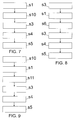
FIG. 4 to FIG. 9 flow diagrams, each representing a method for testing a humidity sensor according to an embodiment of the present invention. -
Figure 1 illustrates a longitudinal cut through a schematic testing arrangement for testing a humidity sensor according to an embodiment of the present invention. - The
humidity sensor 1 comprises asubstrate 11,electrodes 13 arranged on or integrated into thesubstrate 11, and a humiditysensitive layer 12 arranged on thesubstrate 11 covering theelectrodes 13. Thesensitive layer 12 preferably is a polymer layer or a ceramic layer and is susceptible to humidity. A change in a dielectric constant of thesensitive layer 12 results in a change of a capacitance of thesensitive layer 12. Theelectrodes 13 are arranged as planar interdigital electrodes for measuring the capacitance of thesensitive layer 12 by means of an electric field indicated byreference numeral 14 penetrating thesensitive layer 12. A signal provided by theelectrodes 13 may be taken as a measure for the relative amount of water molecules being absorbed in thesensitive layer 12 reflecting the relative humidity of the air surrounding the test arrangement. - A
heater 3 in form of a resistance heater and atemperature sensor 2 are arranged on thesame substrate 11 next to thehumidity sensor 1. Theheater 3 is arranged such that when activated it allows for heating thehumidity sensor 1. Thetemperature sensor 2 is arranged such that it allows for substantially measuring the temperature of thehumidity sensor 1. Advantageously, theheater 3 and thetemperature sensor 2 are arranged close to thehumidity sensor 1, in a preferred embodiment within a radius of 5mm from thehumidity sensor 1, and, in another preferred embodiment, thehumidity sensor 1, thetemperature sensor 2 and theheater 3 are arranged on thecommon substrate 11. Theheater 3 and thetemperature sensor 2 will be used during the testing routine as will be explained later on. - A
control unit 4 is schematically illustrated inFigure 1 as being integrated into thesubstrate 11 whichsubstrate 11 may preferably be a semiconductor substrate. Thecontrol unit 4 may be adapted for testing thehumidity sensor 1. Thecontrol unit 4 is connected to thehumidity sensor 1, thetemperature sensor 2, and theheater 3. It is envisaged that thecontrol unit 4 may receive signals indicative of the relative humidity from thehumidity sensor 1. For such purpose, additional circuitry may be implemented on thesubstrate 11, such as an A/D converter, or circuitry with other functionality. Thecontrol unit 4 may also receive signals indicative of the current temperature from thetemperature sensor 2. Thecontrol unit 4 may also be adapted for activating and deactivating theheater 3 when needed. Thecontrol unit 4 may be adapted for automatically performing a value determination as explained later on and for initiating associated heating and/or cooling actions and/or measurements such that the control unit may perform a built-in self test of the humidity sensor. - Although the relative humidity output by a humidity sensor changes when the temperature is varied - taking a certain delay time into account -, values based on the saturated vapour pressure at the subject temperature and based on the subject relative humidity are expected to remain constant. A tolerance for a value such as the dew point or the absolute humidity may be set. In case the relevant value is a dew point, for example, an allowed tolerance for such dew point may be at some temperature between 0.5° Celsius and 1° Celsius. Any such tolerance may be set subject to the temperature measured. Whenever the calculated value is rising or falling outside the accepted tolerance after a change in temperature, the humidity sensor can be expected to provide false relative humidity values.
- The saturated vapour pressure as a function of the temperature may be given by:
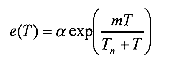
wherein: - e denotes the saturated vapour pressure in Pascal,
- T denotes the temperature in °Celsius,
- m. denotes a first constant,
- Tn denotes a second constant, and
- α denotes a third constant.
- The above formula for the saturated vapour pressure is also known as Magnus formula. Typically, the constant m is set to 17.62, the constant Tn is set to 243.12° Celsius and the constant α is set to 6.112 hPa. However, there may be other formulas and/or approximations which may represent the saturated vapour pressure, too.
- In a preferred embodiment, the values calculated are dew point values F1 and F1 determined for two different temperatures and two associated measured relative humidity values according to

wherein: - F denotes the dew point in °Celsius,
- Φ denotes the relative humidity in %,
- T denotes the temperature in °Celsius,
- m denotes a first constant, and
- Tn denotes a second constant.
- The formula for the dew point is derived from the above Magnus formula. Again, the constant m is set to 17.62, while the constant Tn is set to 243.12° Celsius. With these constants m, Tn the dew point F remains dependent from the relative humidity Φ and the temperature T, wherein the relative humidity Φ itself is dependent from the temperature T, i.e. Φ=f (T). Note that the relative humidity Φ is rising when the temperature T is falling, and vice versa. Other approximations to determining the dew point and/or the underlying saturation vapour pressure may be used instead, or in addition to the above approximation.
- In the present testing arrangement, the relative humidity Φ is measured by the humidity sensor, for example the
humidity sensor 1 ofFigure 1 . The temperature T for which thehumidity sensor 1 provides the associated relative humidity Φ is measured by thetemperature sensor 2. It is noted that the measurements of the temperature T and the associated relative humidity Φ advantageously are performed within a time interval in which it can be expected that the temperature T does not change. As a result, a first relative humidity Φ1 is measured as is the corresponding first temperature T1. When entering the values of Φ1 and T1 into the dew point formula a first dew point F1 can be calculated. - Then, the humidity sensor temperature T is modified and as a result the temperature T of the air volume in the close vicinity of the
humidity sensor 1 becomes modified, too. In the present example, the temperature T of thehumidity sensor 1 is increased by means of theheater 3 ofFigure 1 . After a certain time has passed after activation of theheater 3, in which time it can be expected that the temperature of thehumidity sensor 1 has changed significantly, the current humidity sensor temperature is measured as second temperature T2, as is the associated second relative humidity Φ2. Again, it is preferred that the measurements of the temperature T and the associated relative humidity Φ are performed in a time interval in which it can be expected that the temperature does not change. When entering both values T2 and Φ2 into the dew point formula a second dew point value F2 can be calculated. -
Figure 2 shows a diagram illustrating two dew point characteristics over temperature T. The first dew point characteristic is represented by the two lower dew points F1' and F2' and is based on measurements accomplished with a properly working humidity sensor. A first dew point F1 at the first temperature T1=25° degrees Celsius is calculated to a value F1'=6° degrees Celsius, and a second dew point F2' at the second temperature T2=30° degrees Celsius is calculated to a value F2'=6° degrees Celsius which is equal to the first dew point value F1'. For the reason that the dew point for a properly working humidity sensor remains constant irrespective of a change in the temperature T, a conclusion is legitimate that the present humidity sensor is working properly. - The second dew point characteristic is represented by two upper dew points F1''and F2'' and is based on measurements accomplished with an impaired humidity sensor. The first dew point F1'' at the first temperature T1=25.° degrees Celsius is calculated to a value F1'' of 10° degrees Celsius, and the second dew point F2'' at the second temperature T2=30° degrees Celsius is calculated to a value F2'' of 12° degrees Celsius. A deviation between the dew points F''2 and F''1 is two degrees Celsius which is above a sample threshold TH of one degree Celsius which may, in the present embodiment, represent the critical threshold TH for differentiating between a properly working humidity sensor and an impaired humidity sensor.
- While in the above example, the dew points themselves were evaluated as critical values for determining if the underlying humidity sensor is impaired, in another preferred embodiment, it generally is value V1 and value V2 being analyzed e.g. by means of forming a deviation |V2-V1| between such values V2, V1, which values V2, V1 are based on the saturated vapour pressures for the subject temperatures.
- In a preferred embodiment, such values V1, V2 may represent the absolute humidity AH1, AH2. The absolute humidity AH in [g/m3] is interrelated with the relative humidity - which in this specific example is denoted as RH instead of Φ - in % and the maximum humidity MH in g/m3 by: RH= (AH/MH) *100%.
-
Figure 3 illustrates a relationship between the dew point F in degrees Celsius, the relative humidity RH in % and the absolute humidity AH in g/m3 in form of a diagram including various characteristics for various relative humidity values RH. When using the absolute humidity AH as differentiator value V, it is preferred that the corresponding dew points F are determined in one of the ways as illustrated above. Then, the absolute humidity AH can be determined by using a diagram such as shown inFigure 4 . The information contained in such diagram may preferably be electronically stored in the test arrangement in form of a look up table within thecontrol unit 4. When having the dew point F calculated subject to a measured relative humidity RH and a measured temperature T, the absolute humidity AH can be determined from such look-table. Determining the absolute humidity AH as the relevant value V to be evaluated finally results in two absolute humidity values AH1 and AH2 to be compared with a threshold TH, i.e. |AH2-AH1| >TH, by means of which term it is determined if the humidity sensor is not working properly or not. - In another embodiment, the absolute humidity AH may be defined by

with e actual representing the actual vapour pressure e actual with the actual vapour pressure e actual being related to the saturation vapour pressure e by
- By means of inserting the term for the saturation vapour pressure e in the above equation for the absolute humidity AH, the formula for the absolute humidity AH reads as

wherein: - AH denotes the absolute humidity in g/m3,
- Φ denotes the relative humidity in %,
- T denotes the temperature in °Celsius,
- m denotes a first constant,
- Tn denotes a second constant,
- α denotes a third constant,
- µ denotes a fourth constant, and
- ν denotes a sixth constant.
- Typically, the constant m is set to 17.62, the constant Tn is set to 243.12° Celsius, the constant α is set to 6.112 hPa, the constant µ is set to 216.7, and the constant ν is set to 273.15°C. The constant ν convers the formula into °Celsius measures instead of Kelvin, and the constant µ stems from the ideal gas law and is determined by

wherein
MH2O=18 g/mol representing the molar weight of water,
R = 8.314472 J/mol K
and V representing the volume. - In the following flow diagrams of
Figure 4 to 9 , the same steps are denoted by the same reference numerals across all flow diagrams. -
Figure 4 illustrates a flow diagram representing a method for testing a humidity sensor according to an embodiment of the present invention, preferably based on a testing arrangement as illustrated inFigure 1 . In step s1, the current temperature T1 of thehumidity sensor 1 and the current relative humidity Φ1 are measured by the respective sensors wherein both measurements are taken simultaneously, or are sequentially timed such that it can be expected that the temperature T and the relative humidity Φ have not changed between the measurements. The first temperature T1 and the first relative humidity Φ1 are stored in a memory of thecontrol unit 4. - In step s2, the
heater 3 is activated. The temperature of thehumidity sensor 1 is heated, and after a certain time of heating the elevated temperature of thehumidity sensor 1 is measured as second temperature T2. Alternatively, when the temperature may be monitored continuously, theheater 3 may be switched off when a given second temperature T2 is reached. Its value T2 is taken as measured second temperature T2. In the same step s3, a second relative humidity value Φ2 is measured at the second temperature T2. Again, both measurements of T2 and Φ2 are taken simultaneously, or are sequentially timed such that it can be expected that the temperature and the relative humidity have not changed between the measurements. The second temperature T2 and the second relative humidity Φ2 are stored in a memory of thecontrol unit 4. - In step s4, a first dew point F1 is calculated subject to the measured first temperature T1 and the measured first relative humidity Φ1. In the same step s4, a second dew point F2 is calculated subject to the measured second temperature T2 and the measured second relative humidity Φ2.
- In step s5, the dew points F1 and F2 are evaluated. Preferably, the dew points F1 and F2 are compared to each other, and a deviation | F2-F1 | may be determined. In case the deviation | F2-F1 | exceeds a threshold TH which threshold TH may be interpreted as a tolerance, such that | F2-F1 | > TH, it can be concluded that the
humidity sensor 1 is not working properly. In the same step s5, a signal may be issued when the deviation | F2-F1 | exceeds the threshold TH based on which signal an operator of thehumidity sensor 1 may replace, clean or otherwise repair thehumidity sensor 1. -
Figure 5 illustrates a method according to another embodiment of the present invention, again by means of a flow diagram. The steps s1, s2, s3 and s5 represent the same content as inFigure 4 . For this reason, only the differences with respect to the method illustrated inFigure 4 are emphasized. The method ofFigure 5 differs from the method inFigure 4 in that the calculation of the dew point is immediately performed after the measures needed for the respective calculation are taken. Immediately after measuring the first temperature T1 and the first relative humidity Φ1 in step s1, the first dew point F1 is calculated in step s11. - The same holds for step s31, in which immediately after measuring the second temperature T2 and the second relative humidity Φ2 in step s3, the second dew point F2 is calculated.
- The dew points F1 and F2 may be stored in some memory of the
control unit 4 for a later evaluation in step s5. - In the flow diagram of
Figure 6 , the method as illustrated inFigure 5 is extended by means of confirming the results derived from the first two measurements. The steps s1, s11, s2, s3 and s31 are executed in the same order and represent the same content as inFigure 5 . After having executed the method step s31, the two dew points F1 and F2 are calculated, and the heater still is activated. In subsequent step s6, the heater now is deactivated, and it is waited for a while for allowing the temperature of thehumidity sensor 1 to drop back to the level of the first temperature T1 which represents the initial temperature without any impact of heating. At such point in time, the temperature of thehumidity sensor 1 for safety reasons is measured again in step s7 as third temperature T3, and an associated third relative humidity Φ3 is measured in the same step 7. - In step s71, a third dew point F3 is calculated based on the measured third temperature T3 and the measured third relative humidity Φ3. In subsequent step s5, the first and the second dew points F1 and F2 may be compared to each other, e.g. by means of evaluating a deviation | F2-F1 |. In subsequent step s8, the third and the first dew point F3 and F1 may be compared to each other, e.g. by means of evaluating a deviation | F3-F1 |. In case both of the deviations | F2-F1 | and | F3-F1| are significant and as such e.g. exceed corresponding thresholds TH, another signal may indicate such scenario to the operator.
- The method of
Figure 7 differs from the method ofFigure 4 in that instead of heating thehumidity sensor 1 after having taken the first measurement with respect to relative humidity and temperature, thehumidity sensor 1 is cooled down to a temperature lower than the first temperature T1. As a result, the heating step s2 ofFigure 3 is replaced by a cooling step s10. A cooler may be provided in/for the testing arrangement. After a while during which it can be expected that the temperature has dropped significantly, a second temperature T2 is measured which will be lower than the first temperature T1, as will be measured a second relative humidity Φ2 at the second temperature T2, all in step s3. In step s4, the dew points F1 and F2 are calculated and in step s5, the calculated dew points F1 and F2 are evaluated. - The method of
Figure 8 differs from the method ofFigure 4 in that instead of heating thehumidity sensor 1 after the first measurements are taken thehumidity sensor 1 first is heated in step s3 by means of activating the heater. After a while, the temperature is measured as first temperature T1 in subsequent step s1 as is the first relative humidity Φ1 at such first temperature T1. In subsequent step s6, the heater is deactivated, and after a while, during which it can be expected that the temperature has dropped significantly, and in particular dropped down to the regular temperature without any heating impact, the second measurements are executed in step s3, while the dew points F1 and F2 are calculated in step s4 and the calculated dew points F1 and F2 are evaluated in step s5. - The method of
Figure 9 differs from the method ofFigure 8 in that instead of cooling thehumidity sensor 1 after the first measurements are taken thehumidity sensor 1 first is cooled in step s10 by means of activating a cooler. After a while, the temperature is measured as first temperature T1 in subsequent step s1 as is the first relative humidity Φ1 at such first temperature T1. In the subsequent step s11, the cooler is deactivated, and after a while, during which it can be expected that the temperature has risen significantly, and in particular risen up to the regular temperature without any cooling impact, the second measurements are executed in step s3, while the dew points F1 and F2 are calculated in step s4, and the calculated dew points F1 and F2 are evaluated in step s5. - It is noted that all formulas may be implemented as look up tables which may be easy to store in a computerized memory. Still, the underlying correlation between input and output variables may follow the underlying equations.
Claims (16)
- Method for testing a humidity sensor, comprising the steps of:at a first temperature (T1) measuring a first relative humidity (Φ1) by the humidity sensor (1),calculating a first value (V1) based on the measured first relative humidity (Φ1) and based on a saturated vapour pressure at the first temperature (T1),at a second temperature (T2) measuring a second relative humidity (Φ2) by the humidity sensor (1),calculating a second value (V2) based on the measured second relative humidity (Φ2) and based on a saturated vapour pressure at the second temperature (T2), andevaluating the first value (V1) and the second value (V2) relative to each other.
- Method according to claim 1,
wherein the first value (V1) represents a first dew point (F1), and
wherein the second value (V2) represents a second dew point (F2). - Method according to claim 1,
wherein the first value (V1) represents a first absolute humidity (AH1), and
wherein the second value (V2) represents a second absolute humidity (AH2). - Method according to any one of the preceding claims,
wherein the first and the second values (V1, V2) are determined from a look-up table. - Method according to any one of the preceding claims,
wherein the first temperature (T1) and the second temperature (T2) each represent a temperature of the humidity sensor (1), which temperatures (T1, T2) are measured by a temperature sensor (2) arranged together with the humidity sensor (1) on a common substrate (11). - Method according to any one of the preceding claims,
wherein evaluating the first value (V1) and the second value (V2) relative to each other includes determining a deviation ( | V2-V1 | ) between the first value (V1) and the second value (V2), comparing the deviation ( | V2-V1 | ) with a threshold (TH), and issuing a signal when the deviation ( | V2-V1 | ) exceeds the threshold (TH). - Method according to any one of the preceding claims,
wherein between measuring the first relative humidity (Φ1) and the second relative humidity (Φ2) a heater (3) arranged on a common substrate (11) together with the humidity sensor (1) is activated for increasing the temperature (T) of the humidity sensor (1). - Method according to any one of the preceding claims,
wherein the saturated vapour pressure is given by
wherein:e denotes the saturated vapour pressure in Pascal,T denotes the temperature in °Celsius,m denotes a first constant,Tn denotes a second constant, andα denotes a third constant. - Method according to claim 2,
wherein the dew points (F1, F2) are calculated based on
wherein:F denotes the dew point in °Celsius,Φ denotes the relative humidity in %,T denotes the temperature in °Celsius,m denotes a first constant, and Tn denotes a second constant. - Method according to claim 3, wherein the absolute humidities (AH1, AH2) are calculated based on

wherein:AH denotes the absolute humidity in g/m3,Φ denotes the relative humidity in %,T denotes the temperature in °Celsius,m denotes a first constant,Tn denotes a second constant,α denotes a third constant,µ denotes a fourth constant, andυ denotes a sixth constant. - Method according to any one of the preceding claims,
wherein after measuring the first relative humidity (Φ1) and the second relative humidity (Φ2) a third relative humidity (Φ3) is measured by the humidity sensor (1) at a third temperature (T3),
wherein a third value (V3) is calculated based on the measured third relative humidity (Φ3) and based on a saturated vapour pressure at the third temperature (T3), and
wherein the third value (V3) is evaluated with respect to at least one of the first value (V1) and the second value (V2). - Method according to claim 7 in combination with claim 11,
wherein between measuring the second relative humidity (Φ2) and the third relative humidity (Φ3) the heater (3) is deactivated for allowing the temperature to drop. - Computer program element for testing a humidity sensor,
comprising computer program code means for calculating a first value (V1) based on a saturated vapour pressure at a first temperature (T1) and a first relative humidity (Φ1) measured by a humidity sensor (1) at the first temperature (T1), calculating a second value (V2) based on a saturated vapour pressure at a second temperature (T2) and a second relative humidity (Φ2) measured by the humidity sensor (1) at the second temperature (T2) and comparing the first value (V1) with the second value (V2). - Arrangement for testing a humidity sensor, comprising
the humidity sensor (1),
a temperature sensor (2),
one of a heater (3) and a cooler, and
a control unit (4) adapted for calculating a first value (V1) based on a saturated vapour pressure at a first temperature (T1) measured by the temperature sensor (2) and a first relative humidity (Φ1)measured by the humidity sensor (1) at the first temperature (T1) , calculating a second value (V2) based on a saturated vapour pressure at a second temperature (T2) measured by the temperature sensor (2) and a second relative humidity (Φ2) measured by the humidity sensor (1) at the second temperature (T2) , and comparing the first value (V1) with the second value (V2). - Arrangement according to claim 14, wherein the humidity sensor (1), the temperature sensor (2) and the heater (3) are arranged on a common substrate (11).
- Arrangement according to claim 15, wherein the control unit (4) is arranged on the common substrate (11),
wherein the substrate (11) is a semiconductor substrate, and
wherein the control unit (4) is adapted for automatically performing the calculation, determination and comparison steps with respect to the values (V1, V2) and for initiating associated measurements and/or heating and/or cooling actions for providing an automated self-test for the humidity sensor (1).
Priority Applications (2)
| Application Number | Priority Date | Filing Date | Title |
|---|---|---|---|
| EP11002800.8A EP2508881B1 (en) | 2011-04-04 | 2011-04-04 | Testing a humidity sensor |
| US13/415,284 US20120253691A1 (en) | 2011-04-04 | 2012-03-08 | Testing a humidity sensor |
Applications Claiming Priority (1)
| Application Number | Priority Date | Filing Date | Title |
|---|---|---|---|
| EP11002800.8A EP2508881B1 (en) | 2011-04-04 | 2011-04-04 | Testing a humidity sensor |
Publications (2)
| Publication Number | Publication Date |
|---|---|
| EP2508881A1 true EP2508881A1 (en) | 2012-10-10 |
| EP2508881B1 EP2508881B1 (en) | 2019-01-23 |
Family
ID=44276075
Family Applications (1)
| Application Number | Title | Priority Date | Filing Date |
|---|---|---|---|
| EP11002800.8A Active EP2508881B1 (en) | 2011-04-04 | 2011-04-04 | Testing a humidity sensor |
Country Status (2)
| Country | Link |
|---|---|
| US (1) | US20120253691A1 (en) |
| EP (1) | EP2508881B1 (en) |
Cited By (5)
| Publication number | Priority date | Publication date | Assignee | Title |
|---|---|---|---|---|
| WO2015117692A1 (en) * | 2014-02-07 | 2015-08-13 | Robert Bosch Gmbh | Capacitive sensor for detecting a medium, and corresponding method |
| US9312713B2 (en) | 2012-03-20 | 2016-04-12 | Sensirion Ag | Heating a sensitive layer of a chemical sensor subject to detection of a recharge process in an electronic device |
| CN105829874A (en) * | 2013-12-10 | 2016-08-03 | 日立汽车系统株式会社 | Humidity measurement device |
| US9772317B2 (en) | 2012-07-26 | 2017-09-26 | Sensirion Ag | Method for operating a portable electronic device |
| EP3379218A1 (en) * | 2017-03-21 | 2018-09-26 | MEAS France | Method for providing a diagnostic on a combined humidity and temperature sensor |
Families Citing this family (10)
| Publication number | Priority date | Publication date | Assignee | Title |
|---|---|---|---|---|
| EP2808652B1 (en) | 2013-05-31 | 2016-11-16 | Sensirion AG | Portable electronic device with integrated temperature sensor being compensated by other sensing data |
| DE102013211378B4 (en) * | 2013-06-18 | 2021-05-20 | Robert Bosch Gmbh | Micromechanical humidity sensor device and corresponding manufacturing process as well as micromechanical sensor arrangement |
| EP2910938B1 (en) | 2014-02-25 | 2017-09-06 | Sensirion AG | Portable electronic device |
| WO2015151947A1 (en) * | 2014-04-04 | 2015-10-08 | 日立オートモティブシステムズ株式会社 | Humidity detection device |
| JP6421763B2 (en) * | 2016-01-13 | 2018-11-14 | トヨタ自動車株式会社 | Abnormality detection device for humidity sensor |
| US10935508B2 (en) * | 2017-08-28 | 2021-03-02 | Xiamen Eco Lighting Co. Ltd. | Liquid detection device and liquid detection system for abnormal liquid on a surface |
| EP3705885A1 (en) | 2019-03-06 | 2020-09-09 | ams AG | Sensor device and method for operating a sensor device |
| KR20230020164A (en) * | 2021-08-03 | 2023-02-10 | 엘지전자 주식회사 | a refrigerator and operating method thereof |
| WO2026047557A1 (en) * | 2024-08-30 | 2026-03-05 | Spea S.P.A. | Method and apparatus for testing humidity sensors |
| CN119223453A (en) * | 2024-09-02 | 2024-12-31 | 湖南旭安消防工程有限公司 | A fire protection cable detection device |
Citations (4)
| Publication number | Priority date | Publication date | Assignee | Title |
|---|---|---|---|---|
| GB2097130A (en) * | 1981-04-04 | 1982-10-27 | Moisture Control & Mesurement | Moisture measurement |
| US5792938A (en) * | 1996-12-13 | 1998-08-11 | Panametrics, Inc. | Humidity sensor with differential thermal detection and method of sensing |
| EP1236038B1 (en) | 1999-12-08 | 2005-11-23 | Sensirion AG | Capacitive sensor |
| JP2010237130A (en) * | 2009-03-31 | 2010-10-21 | Yamatake Corp | Degradation diagnosis method for humidity sensor |
Family Cites Families (1)
| Publication number | Priority date | Publication date | Assignee | Title |
|---|---|---|---|---|
| EP1730506B1 (en) * | 2004-04-02 | 2018-09-26 | Silicon Laboratories Inc. | An integrated electronic sensor |
-
2011
- 2011-04-04 EP EP11002800.8A patent/EP2508881B1/en active Active
-
2012
- 2012-03-08 US US13/415,284 patent/US20120253691A1/en not_active Abandoned
Patent Citations (4)
| Publication number | Priority date | Publication date | Assignee | Title |
|---|---|---|---|---|
| GB2097130A (en) * | 1981-04-04 | 1982-10-27 | Moisture Control & Mesurement | Moisture measurement |
| US5792938A (en) * | 1996-12-13 | 1998-08-11 | Panametrics, Inc. | Humidity sensor with differential thermal detection and method of sensing |
| EP1236038B1 (en) | 1999-12-08 | 2005-11-23 | Sensirion AG | Capacitive sensor |
| JP2010237130A (en) * | 2009-03-31 | 2010-10-21 | Yamatake Corp | Degradation diagnosis method for humidity sensor |
Cited By (11)
| Publication number | Priority date | Publication date | Assignee | Title |
|---|---|---|---|---|
| US9312713B2 (en) | 2012-03-20 | 2016-04-12 | Sensirion Ag | Heating a sensitive layer of a chemical sensor subject to detection of a recharge process in an electronic device |
| US9772317B2 (en) | 2012-07-26 | 2017-09-26 | Sensirion Ag | Method for operating a portable electronic device |
| CN105829874A (en) * | 2013-12-10 | 2016-08-03 | 日立汽车系统株式会社 | Humidity measurement device |
| EP3081929A4 (en) * | 2013-12-10 | 2017-07-12 | Hitachi Automotive Systems, Ltd. | Humidity measurement device |
| US9970396B2 (en) | 2013-12-10 | 2018-05-15 | Hitachi Automotive Systems, Ltd. | Intake air humidity measurement device for an internal combustion engine |
| WO2015117692A1 (en) * | 2014-02-07 | 2015-08-13 | Robert Bosch Gmbh | Capacitive sensor for detecting a medium, and corresponding method |
| DE102014202248A1 (en) | 2014-02-07 | 2015-08-27 | Robert Bosch Gmbh | Sensor for detecting at least one medium and method for operating a capacitive measuring device |
| US10613049B2 (en) | 2014-02-07 | 2020-04-07 | Robert Bosch Gmbh | Capacitive sensor for detecting a medium, and corresponding method |
| EP3379218A1 (en) * | 2017-03-21 | 2018-09-26 | MEAS France | Method for providing a diagnostic on a combined humidity and temperature sensor |
| CN108627198A (en) * | 2017-03-21 | 2018-10-09 | 梅斯法国公司 | Method for providing diagnosis in the humidity of combination and temperature sensor |
| US10950069B2 (en) | 2017-03-21 | 2021-03-16 | MEAS France | Method for providing a diagnostic on a combined humidity and temperature sensor |
Also Published As
| Publication number | Publication date |
|---|---|
| EP2508881B1 (en) | 2019-01-23 |
| US20120253691A1 (en) | 2012-10-04 |
Similar Documents
| Publication | Publication Date | Title |
|---|---|---|
| EP2508881B1 (en) | Testing a humidity sensor | |
| GB2499842A (en) | Temperature regulated multiple gas sensor | |
| CN102597754B (en) | hydrogen chlorine level detector | |
| KR20150036605A (en) | System and method for detecting used and dried sensors | |
| CN109900310B (en) | A kind of temperature and humidity sensor self-test method | |
| US6779385B2 (en) | Method and device for monitoring moisture content of an immersed solid dielectric material | |
| CN106706165A (en) | Method and device for measuring temperature | |
| JP2016505840A5 (en) | ||
| CN106092375B (en) | The method of calibration and tester of airborne equipment surface temperature sensor | |
| US9835574B2 (en) | Gas measurement device and measurement method thereof | |
| JP2025143334A (en) | Compensation system and method for thermistor sensing in an analyte biosensor - Patent Application 20070122999 | |
| KR102534577B1 (en) | Gas analysis system and gas analysis method | |
| US8287182B2 (en) | Method for testing a frying oil tester | |
| EP2012115A2 (en) | Chemiresistor sensor system compensated for temperature and aging effects | |
| CN204730958U (en) | NTC temperature sensor thermal time constant proving installation | |
| RU2376644C2 (en) | Fire alarm system with linear detectors, based on merging data, and method of making said alarm | |
| EP2930502A1 (en) | Gas sensor | |
| US5872454A (en) | Calibration procedure that improves accuracy of electrolytic conductivity measurement systems | |
| CN114624295B (en) | Gas measuring instrument | |
| KR101827518B1 (en) | Method for detecting sensor, sensor detection system performing the same, and storage medium storing the same | |
| EP3299795A1 (en) | Dynamic moisture absorption-desorption property evaluation apparatus, method for evaluating dynamic moisture absorption-desorption property , and dynamic moisture absorption-desorption property evaluation program | |
| EP1921444A1 (en) | Exhaust gas sensors and methods for measuring concentrations of nox and ammonia and temperatures of the sensors | |
| CN105286812A (en) | Body temperature measurement method and device | |
| US6112576A (en) | Gas analyzer with background gas compensation | |
| US11988624B2 (en) | Method for detecting at least one gas quantity of at least one predetermined gas by a measurement sensor of a plurality of gases |
Legal Events
| Date | Code | Title | Description |
|---|---|---|---|
| PUAI | Public reference made under article 153(3) epc to a published international application that has entered the european phase |
Free format text: ORIGINAL CODE: 0009012 |
|
| AK | Designated contracting states |
Kind code of ref document: A1 Designated state(s): AL AT BE BG CH CY CZ DE DK EE ES FI FR GB GR HR HU IE IS IT LI LT LU LV MC MK MT NL NO PL PT RO RS SE SI SK SM TR |
|
| AX | Request for extension of the european patent |
Extension state: BA ME |
|
| 17P | Request for examination filed |
Effective date: 20130410 |
|
| STAA | Information on the status of an ep patent application or granted ep patent |
Free format text: STATUS: EXAMINATION IS IN PROGRESS |
|
| 17Q | First examination report despatched |
Effective date: 20170224 |
|
| GRAP | Despatch of communication of intention to grant a patent |
Free format text: ORIGINAL CODE: EPIDOSNIGR1 |
|
| STAA | Information on the status of an ep patent application or granted ep patent |
Free format text: STATUS: GRANT OF PATENT IS INTENDED |
|
| INTG | Intention to grant announced |
Effective date: 20180912 |
|
| GRAS | Grant fee paid |
Free format text: ORIGINAL CODE: EPIDOSNIGR3 |
|
| GRAJ | Information related to disapproval of communication of intention to grant by the applicant or resumption of examination proceedings by the epo deleted |
Free format text: ORIGINAL CODE: EPIDOSDIGR1 |
|
| GRAL | Information related to payment of fee for publishing/printing deleted |
Free format text: ORIGINAL CODE: EPIDOSDIGR3 |
|
| STAA | Information on the status of an ep patent application or granted ep patent |
Free format text: STATUS: EXAMINATION IS IN PROGRESS |
|
| GRAR | Information related to intention to grant a patent recorded |
Free format text: ORIGINAL CODE: EPIDOSNIGR71 |
|
| STAA | Information on the status of an ep patent application or granted ep patent |
Free format text: STATUS: GRANT OF PATENT IS INTENDED |
|
| GRAA | (expected) grant |
Free format text: ORIGINAL CODE: 0009210 |
|
| STAA | Information on the status of an ep patent application or granted ep patent |
Free format text: STATUS: THE PATENT HAS BEEN GRANTED |
|
| INTC | Intention to grant announced (deleted) | ||
| AK | Designated contracting states |
Kind code of ref document: B1 Designated state(s): AL AT BE BG CH CY CZ DE DK EE ES FI FR GB GR HR HU IE IS IT LI LT LU LV MC MK MT NL NO PL PT RO RS SE SI SK SM TR |
|
| INTG | Intention to grant announced |
Effective date: 20181217 |
|
| REG | Reference to a national code |
Ref country code: GB Ref legal event code: FG4D |
|
| REG | Reference to a national code |
Ref country code: CH Ref legal event code: EP |
|
| REG | Reference to a national code |
Ref country code: AT Ref legal event code: REF Ref document number: 1091848 Country of ref document: AT Kind code of ref document: T Effective date: 20190215 |
|
| REG | Reference to a national code |
Ref country code: IE Ref legal event code: FG4D |
|
| REG | Reference to a national code |
Ref country code: DE Ref legal event code: R096 Ref document number: 602011055841 Country of ref document: DE |
|
| REG | Reference to a national code |
Ref country code: NL Ref legal event code: MP Effective date: 20190123 |
|
| PG25 | Lapsed in a contracting state [announced via postgrant information from national office to epo] |
Ref country code: NL Free format text: LAPSE BECAUSE OF FAILURE TO SUBMIT A TRANSLATION OF THE DESCRIPTION OR TO PAY THE FEE WITHIN THE PRESCRIBED TIME-LIMIT Effective date: 20190123 |
|
| PG25 | Lapsed in a contracting state [announced via postgrant information from national office to epo] |
Ref country code: FI Free format text: LAPSE BECAUSE OF FAILURE TO SUBMIT A TRANSLATION OF THE DESCRIPTION OR TO PAY THE FEE WITHIN THE PRESCRIBED TIME-LIMIT Effective date: 20190123 Ref country code: NO Free format text: LAPSE BECAUSE OF FAILURE TO SUBMIT A TRANSLATION OF THE DESCRIPTION OR TO PAY THE FEE WITHIN THE PRESCRIBED TIME-LIMIT Effective date: 20190423 Ref country code: ES Free format text: LAPSE BECAUSE OF FAILURE TO SUBMIT A TRANSLATION OF THE DESCRIPTION OR TO PAY THE FEE WITHIN THE PRESCRIBED TIME-LIMIT Effective date: 20190123 Ref country code: PT Free format text: LAPSE BECAUSE OF FAILURE TO SUBMIT A TRANSLATION OF THE DESCRIPTION OR TO PAY THE FEE WITHIN THE PRESCRIBED TIME-LIMIT Effective date: 20190523 Ref country code: SE Free format text: LAPSE BECAUSE OF FAILURE TO SUBMIT A TRANSLATION OF THE DESCRIPTION OR TO PAY THE FEE WITHIN THE PRESCRIBED TIME-LIMIT Effective date: 20190123 Ref country code: PL Free format text: LAPSE BECAUSE OF FAILURE TO SUBMIT A TRANSLATION OF THE DESCRIPTION OR TO PAY THE FEE WITHIN THE PRESCRIBED TIME-LIMIT Effective date: 20190123 Ref country code: LT Free format text: LAPSE BECAUSE OF FAILURE TO SUBMIT A TRANSLATION OF THE DESCRIPTION OR TO PAY THE FEE WITHIN THE PRESCRIBED TIME-LIMIT Effective date: 20190123 |
|
| REG | Reference to a national code |
Ref country code: AT Ref legal event code: MK05 Ref document number: 1091848 Country of ref document: AT Kind code of ref document: T Effective date: 20190123 |
|
| PG25 | Lapsed in a contracting state [announced via postgrant information from national office to epo] |
Ref country code: LV Free format text: LAPSE BECAUSE OF FAILURE TO SUBMIT A TRANSLATION OF THE DESCRIPTION OR TO PAY THE FEE WITHIN THE PRESCRIBED TIME-LIMIT Effective date: 20190123 Ref country code: HR Free format text: LAPSE BECAUSE OF FAILURE TO SUBMIT A TRANSLATION OF THE DESCRIPTION OR TO PAY THE FEE WITHIN THE PRESCRIBED TIME-LIMIT Effective date: 20190123 Ref country code: GR Free format text: LAPSE BECAUSE OF FAILURE TO SUBMIT A TRANSLATION OF THE DESCRIPTION OR TO PAY THE FEE WITHIN THE PRESCRIBED TIME-LIMIT Effective date: 20190424 Ref country code: IS Free format text: LAPSE BECAUSE OF FAILURE TO SUBMIT A TRANSLATION OF THE DESCRIPTION OR TO PAY THE FEE WITHIN THE PRESCRIBED TIME-LIMIT Effective date: 20190523 Ref country code: RS Free format text: LAPSE BECAUSE OF FAILURE TO SUBMIT A TRANSLATION OF THE DESCRIPTION OR TO PAY THE FEE WITHIN THE PRESCRIBED TIME-LIMIT Effective date: 20190123 Ref country code: BG Free format text: LAPSE BECAUSE OF FAILURE TO SUBMIT A TRANSLATION OF THE DESCRIPTION OR TO PAY THE FEE WITHIN THE PRESCRIBED TIME-LIMIT Effective date: 20190423 |
|
| REG | Reference to a national code |
Ref country code: DE Ref legal event code: R097 Ref document number: 602011055841 Country of ref document: DE |
|
| PG25 | Lapsed in a contracting state [announced via postgrant information from national office to epo] |
Ref country code: DK Free format text: LAPSE BECAUSE OF FAILURE TO SUBMIT A TRANSLATION OF THE DESCRIPTION OR TO PAY THE FEE WITHIN THE PRESCRIBED TIME-LIMIT Effective date: 20190123 Ref country code: EE Free format text: LAPSE BECAUSE OF FAILURE TO SUBMIT A TRANSLATION OF THE DESCRIPTION OR TO PAY THE FEE WITHIN THE PRESCRIBED TIME-LIMIT Effective date: 20190123 Ref country code: IT Free format text: LAPSE BECAUSE OF FAILURE TO SUBMIT A TRANSLATION OF THE DESCRIPTION OR TO PAY THE FEE WITHIN THE PRESCRIBED TIME-LIMIT Effective date: 20190123 Ref country code: RO Free format text: LAPSE BECAUSE OF FAILURE TO SUBMIT A TRANSLATION OF THE DESCRIPTION OR TO PAY THE FEE WITHIN THE PRESCRIBED TIME-LIMIT Effective date: 20190123 Ref country code: CZ Free format text: LAPSE BECAUSE OF FAILURE TO SUBMIT A TRANSLATION OF THE DESCRIPTION OR TO PAY THE FEE WITHIN THE PRESCRIBED TIME-LIMIT Effective date: 20190123 Ref country code: AL Free format text: LAPSE BECAUSE OF FAILURE TO SUBMIT A TRANSLATION OF THE DESCRIPTION OR TO PAY THE FEE WITHIN THE PRESCRIBED TIME-LIMIT Effective date: 20190123 Ref country code: SK Free format text: LAPSE BECAUSE OF FAILURE TO SUBMIT A TRANSLATION OF THE DESCRIPTION OR TO PAY THE FEE WITHIN THE PRESCRIBED TIME-LIMIT Effective date: 20190123 |
|
| PG25 | Lapsed in a contracting state [announced via postgrant information from national office to epo] |
Ref country code: SM Free format text: LAPSE BECAUSE OF FAILURE TO SUBMIT A TRANSLATION OF THE DESCRIPTION OR TO PAY THE FEE WITHIN THE PRESCRIBED TIME-LIMIT Effective date: 20190123 |
|
| PLBE | No opposition filed within time limit |
Free format text: ORIGINAL CODE: 0009261 |
|
| STAA | Information on the status of an ep patent application or granted ep patent |
Free format text: STATUS: NO OPPOSITION FILED WITHIN TIME LIMIT |
|
| REG | Reference to a national code |
Ref country code: BE Ref legal event code: MM Effective date: 20190430 |
|
| PG25 | Lapsed in a contracting state [announced via postgrant information from national office to epo] |
Ref country code: MC Free format text: LAPSE BECAUSE OF FAILURE TO SUBMIT A TRANSLATION OF THE DESCRIPTION OR TO PAY THE FEE WITHIN THE PRESCRIBED TIME-LIMIT Effective date: 20190123 Ref country code: AT Free format text: LAPSE BECAUSE OF FAILURE TO SUBMIT A TRANSLATION OF THE DESCRIPTION OR TO PAY THE FEE WITHIN THE PRESCRIBED TIME-LIMIT Effective date: 20190123 Ref country code: LU Free format text: LAPSE BECAUSE OF NON-PAYMENT OF DUE FEES Effective date: 20190404 |
|
| 26N | No opposition filed |
Effective date: 20191024 |
|
| PG25 | Lapsed in a contracting state [announced via postgrant information from national office to epo] |
Ref country code: SI Free format text: LAPSE BECAUSE OF FAILURE TO SUBMIT A TRANSLATION OF THE DESCRIPTION OR TO PAY THE FEE WITHIN THE PRESCRIBED TIME-LIMIT Effective date: 20190123 Ref country code: BE Free format text: LAPSE BECAUSE OF NON-PAYMENT OF DUE FEES Effective date: 20190430 |
|
| PG25 | Lapsed in a contracting state [announced via postgrant information from national office to epo] |
Ref country code: TR Free format text: LAPSE BECAUSE OF FAILURE TO SUBMIT A TRANSLATION OF THE DESCRIPTION OR TO PAY THE FEE WITHIN THE PRESCRIBED TIME-LIMIT Effective date: 20190123 |
|
| PG25 | Lapsed in a contracting state [announced via postgrant information from national office to epo] |
Ref country code: IE Free format text: LAPSE BECAUSE OF NON-PAYMENT OF DUE FEES Effective date: 20190404 |
|
| PG25 | Lapsed in a contracting state [announced via postgrant information from national office to epo] |
Ref country code: CY Free format text: LAPSE BECAUSE OF FAILURE TO SUBMIT A TRANSLATION OF THE DESCRIPTION OR TO PAY THE FEE WITHIN THE PRESCRIBED TIME-LIMIT Effective date: 20190123 |
|
| PG25 | Lapsed in a contracting state [announced via postgrant information from national office to epo] |
Ref country code: HU Free format text: LAPSE BECAUSE OF FAILURE TO SUBMIT A TRANSLATION OF THE DESCRIPTION OR TO PAY THE FEE WITHIN THE PRESCRIBED TIME-LIMIT; INVALID AB INITIO Effective date: 20110404 Ref country code: MT Free format text: LAPSE BECAUSE OF FAILURE TO SUBMIT A TRANSLATION OF THE DESCRIPTION OR TO PAY THE FEE WITHIN THE PRESCRIBED TIME-LIMIT Effective date: 20190123 |
|
| PG25 | Lapsed in a contracting state [announced via postgrant information from national office to epo] |
Ref country code: MK Free format text: LAPSE BECAUSE OF FAILURE TO SUBMIT A TRANSLATION OF THE DESCRIPTION OR TO PAY THE FEE WITHIN THE PRESCRIBED TIME-LIMIT Effective date: 20190123 |
|
| P01 | Opt-out of the competence of the unified patent court (upc) registered |
Effective date: 20230602 |
|
| PGFP | Annual fee paid to national office [announced via postgrant information from national office to epo] |
Ref country code: DE Payment date: 20250417 Year of fee payment: 15 |
|
| PGFP | Annual fee paid to national office [announced via postgrant information from national office to epo] |
Ref country code: FR Payment date: 20250422 Year of fee payment: 15 |
|
| PGFP | Annual fee paid to national office [announced via postgrant information from national office to epo] |
Ref country code: CH Payment date: 20250423 Year of fee payment: 15 |
|
| PGFP | Annual fee paid to national office [announced via postgrant information from national office to epo] |
Ref country code: GB Payment date: 20260324 Year of fee payment: 16 |
|
| REG | Reference to a national code |
Ref country code: CH Ref legal event code: U11 Free format text: ST27 STATUS EVENT CODE: U-0-0-U10-U11 (AS PROVIDED BY THE NATIONAL OFFICE) Effective date: 20260501 |