EP2508779A1 - Method of producing a seal member - Google Patents
Method of producing a seal member Download PDFInfo
- Publication number
- EP2508779A1 EP2508779A1 EP12160147A EP12160147A EP2508779A1 EP 2508779 A1 EP2508779 A1 EP 2508779A1 EP 12160147 A EP12160147 A EP 12160147A EP 12160147 A EP12160147 A EP 12160147A EP 2508779 A1 EP2508779 A1 EP 2508779A1
- Authority
- EP
- European Patent Office
- Prior art keywords
- seal member
- seal
- fine particles
- elastic
- molded
- Prior art date
- Legal status (The legal status is an assumption and is not a legal conclusion. Google has not performed a legal analysis and makes no representation as to the accuracy of the status listed.)
- Withdrawn
Links
- 238000000034 method Methods 0.000 title claims abstract description 16
- 239000010419 fine particle Substances 0.000 claims abstract description 23
- 238000000465 moulding Methods 0.000 claims abstract description 16
- 239000000463 material Substances 0.000 claims abstract description 12
- 239000002245 particle Substances 0.000 claims abstract description 10
- 238000004898 kneading Methods 0.000 claims abstract description 9
- 239000013013 elastic material Substances 0.000 claims abstract description 7
- 239000007788 liquid Substances 0.000 claims description 4
- 238000005096 rolling process Methods 0.000 description 10
- 239000002184 metal Substances 0.000 description 8
- XLYOFNOQVPJJNP-UHFFFAOYSA-N water Substances O XLYOFNOQVPJJNP-UHFFFAOYSA-N 0.000 description 8
- 238000007789 sealing Methods 0.000 description 7
- 238000005304 joining Methods 0.000 description 4
- 238000005452 bending Methods 0.000 description 3
- 238000004519 manufacturing process Methods 0.000 description 3
- 206010000496 acne Diseases 0.000 description 2
- 239000000853 adhesive Substances 0.000 description 1
- 230000001070 adhesive effect Effects 0.000 description 1
- 230000002411 adverse Effects 0.000 description 1
- 239000000446 fuel Substances 0.000 description 1
- 239000000314 lubricant Substances 0.000 description 1
- 239000011347 resin Substances 0.000 description 1
- 229920005989 resin Polymers 0.000 description 1
- 230000000717 retained effect Effects 0.000 description 1
- 150000003839 salts Chemical class 0.000 description 1
- 238000011144 upstream manufacturing Methods 0.000 description 1
Images


Classifications
-
- F—MECHANICAL ENGINEERING; LIGHTING; HEATING; WEAPONS; BLASTING
- F16—ENGINEERING ELEMENTS AND UNITS; GENERAL MEASURES FOR PRODUCING AND MAINTAINING EFFECTIVE FUNCTIONING OF MACHINES OR INSTALLATIONS; THERMAL INSULATION IN GENERAL
- F16J—PISTONS; CYLINDERS; SEALINGS
- F16J15/00—Sealings
- F16J15/16—Sealings between relatively-moving surfaces
- F16J15/32—Sealings between relatively-moving surfaces with elastic sealings, e.g. O-rings
- F16J15/328—Manufacturing methods specially adapted for elastic sealings
-
- B—PERFORMING OPERATIONS; TRANSPORTING
- B29—WORKING OF PLASTICS; WORKING OF SUBSTANCES IN A PLASTIC STATE IN GENERAL
- B29C—SHAPING OR JOINING OF PLASTICS; SHAPING OF MATERIAL IN A PLASTIC STATE, NOT OTHERWISE PROVIDED FOR; AFTER-TREATMENT OF THE SHAPED PRODUCTS, e.g. REPAIRING
- B29C45/00—Injection moulding, i.e. forcing the required volume of moulding material through a nozzle into a closed mould; Apparatus therefor
- B29C45/0013—Injection moulding, i.e. forcing the required volume of moulding material through a nozzle into a closed mould; Apparatus therefor using fillers dispersed in the moulding material, e.g. metal particles
-
- F—MECHANICAL ENGINEERING; LIGHTING; HEATING; WEAPONS; BLASTING
- F16—ENGINEERING ELEMENTS AND UNITS; GENERAL MEASURES FOR PRODUCING AND MAINTAINING EFFECTIVE FUNCTIONING OF MACHINES OR INSTALLATIONS; THERMAL INSULATION IN GENERAL
- F16C—SHAFTS; FLEXIBLE SHAFTS; ELEMENTS OR CRANKSHAFT MECHANISMS; ROTARY BODIES OTHER THAN GEARING ELEMENTS; BEARINGS
- F16C33/00—Parts of bearings; Special methods for making bearings or parts thereof
- F16C33/72—Sealings
- F16C33/76—Sealings of ball or roller bearings
- F16C33/78—Sealings of ball or roller bearings with a diaphragm, disc, or ring, with or without resilient members
- F16C33/7816—Details of the sealing or parts thereof, e.g. geometry, material
- F16C33/7833—Special methods of manufacture
-
- F—MECHANICAL ENGINEERING; LIGHTING; HEATING; WEAPONS; BLASTING
- F16—ENGINEERING ELEMENTS AND UNITS; GENERAL MEASURES FOR PRODUCING AND MAINTAINING EFFECTIVE FUNCTIONING OF MACHINES OR INSTALLATIONS; THERMAL INSULATION IN GENERAL
- F16C—SHAFTS; FLEXIBLE SHAFTS; ELEMENTS OR CRANKSHAFT MECHANISMS; ROTARY BODIES OTHER THAN GEARING ELEMENTS; BEARINGS
- F16C33/00—Parts of bearings; Special methods for making bearings or parts thereof
- F16C33/72—Sealings
- F16C33/76—Sealings of ball or roller bearings
- F16C33/78—Sealings of ball or roller bearings with a diaphragm, disc, or ring, with or without resilient members
- F16C33/7869—Sealings of ball or roller bearings with a diaphragm, disc, or ring, with or without resilient members mounted with a cylindrical portion to the inner surface of the outer race and having a radial portion extending inward
- F16C33/7873—Sealings of ball or roller bearings with a diaphragm, disc, or ring, with or without resilient members mounted with a cylindrical portion to the inner surface of the outer race and having a radial portion extending inward with a single sealing ring of generally L-shaped cross-section
- F16C33/7876—Sealings of ball or roller bearings with a diaphragm, disc, or ring, with or without resilient members mounted with a cylindrical portion to the inner surface of the outer race and having a radial portion extending inward with a single sealing ring of generally L-shaped cross-section with sealing lips
-
- F—MECHANICAL ENGINEERING; LIGHTING; HEATING; WEAPONS; BLASTING
- F16—ENGINEERING ELEMENTS AND UNITS; GENERAL MEASURES FOR PRODUCING AND MAINTAINING EFFECTIVE FUNCTIONING OF MACHINES OR INSTALLATIONS; THERMAL INSULATION IN GENERAL
- F16C—SHAFTS; FLEXIBLE SHAFTS; ELEMENTS OR CRANKSHAFT MECHANISMS; ROTARY BODIES OTHER THAN GEARING ELEMENTS; BEARINGS
- F16C33/00—Parts of bearings; Special methods for making bearings or parts thereof
- F16C33/72—Sealings
- F16C33/76—Sealings of ball or roller bearings
- F16C33/78—Sealings of ball or roller bearings with a diaphragm, disc, or ring, with or without resilient members
- F16C33/7869—Sealings of ball or roller bearings with a diaphragm, disc, or ring, with or without resilient members mounted with a cylindrical portion to the inner surface of the outer race and having a radial portion extending inward
- F16C33/7879—Sealings of ball or roller bearings with a diaphragm, disc, or ring, with or without resilient members mounted with a cylindrical portion to the inner surface of the outer race and having a radial portion extending inward with a further sealing ring
-
- B—PERFORMING OPERATIONS; TRANSPORTING
- B29—WORKING OF PLASTICS; WORKING OF SUBSTANCES IN A PLASTIC STATE IN GENERAL
- B29C—SHAPING OR JOINING OF PLASTICS; SHAPING OF MATERIAL IN A PLASTIC STATE, NOT OTHERWISE PROVIDED FOR; AFTER-TREATMENT OF THE SHAPED PRODUCTS, e.g. REPAIRING
- B29C45/00—Injection moulding, i.e. forcing the required volume of moulding material through a nozzle into a closed mould; Apparatus therefor
- B29C45/0053—Injection moulding, i.e. forcing the required volume of moulding material through a nozzle into a closed mould; Apparatus therefor combined with a final operation, e.g. shaping
- B29C45/0055—Shaping
- B29C2045/0058—Shaping removing material
-
- B—PERFORMING OPERATIONS; TRANSPORTING
- B29—WORKING OF PLASTICS; WORKING OF SUBSTANCES IN A PLASTIC STATE IN GENERAL
- B29L—INDEXING SCHEME ASSOCIATED WITH SUBCLASS B29C, RELATING TO PARTICULAR ARTICLES
- B29L2031/00—Other particular articles
- B29L2031/04—Bearings
-
- F—MECHANICAL ENGINEERING; LIGHTING; HEATING; WEAPONS; BLASTING
- F16—ENGINEERING ELEMENTS AND UNITS; GENERAL MEASURES FOR PRODUCING AND MAINTAINING EFFECTIVE FUNCTIONING OF MACHINES OR INSTALLATIONS; THERMAL INSULATION IN GENERAL
- F16C—SHAFTS; FLEXIBLE SHAFTS; ELEMENTS OR CRANKSHAFT MECHANISMS; ROTARY BODIES OTHER THAN GEARING ELEMENTS; BEARINGS
- F16C19/00—Bearings with rolling contact, for exclusively rotary movement
- F16C19/02—Bearings with rolling contact, for exclusively rotary movement with bearing balls essentially of the same size in one or more circular rows
- F16C19/14—Bearings with rolling contact, for exclusively rotary movement with bearing balls essentially of the same size in one or more circular rows for both radial and axial load
- F16C19/18—Bearings with rolling contact, for exclusively rotary movement with bearing balls essentially of the same size in one or more circular rows for both radial and axial load with two or more rows of balls
- F16C19/181—Bearings with rolling contact, for exclusively rotary movement with bearing balls essentially of the same size in one or more circular rows for both radial and axial load with two or more rows of balls with angular contact
- F16C19/183—Bearings with rolling contact, for exclusively rotary movement with bearing balls essentially of the same size in one or more circular rows for both radial and axial load with two or more rows of balls with angular contact with two rows at opposite angles
- F16C19/184—Bearings with rolling contact, for exclusively rotary movement with bearing balls essentially of the same size in one or more circular rows for both radial and axial load with two or more rows of balls with angular contact with two rows at opposite angles in O-arrangement
- F16C19/186—Bearings with rolling contact, for exclusively rotary movement with bearing balls essentially of the same size in one or more circular rows for both radial and axial load with two or more rows of balls with angular contact with two rows at opposite angles in O-arrangement with three raceways provided integrally on parts other than race rings, e.g. third generation hubs
-
- F—MECHANICAL ENGINEERING; LIGHTING; HEATING; WEAPONS; BLASTING
- F16—ENGINEERING ELEMENTS AND UNITS; GENERAL MEASURES FOR PRODUCING AND MAINTAINING EFFECTIVE FUNCTIONING OF MACHINES OR INSTALLATIONS; THERMAL INSULATION IN GENERAL
- F16C—SHAFTS; FLEXIBLE SHAFTS; ELEMENTS OR CRANKSHAFT MECHANISMS; ROTARY BODIES OTHER THAN GEARING ELEMENTS; BEARINGS
- F16C2326/00—Articles relating to transporting
- F16C2326/01—Parts of vehicles in general
- F16C2326/02—Wheel hubs or castors
Definitions
- the invention relates to a method of producing a seal member.
- a known example of a seal member used in a rolling bearing device for a wheel, for example, for sealing an annular space between an inner ring member and an outer ring member includes a fixed portion fixed to an inner periphery of the outer ring member, and a lip that is in sliding contact with the vicinity of a raceway shoulder portion of the inner ring member.
- the seal member as described above if two or more lips are formed, or the elastic force of the lip(s) is increased so as to enhance the sealing performance, the sliding resistance increases, resulting in an adverse influence on the fuel efficiency and significant wear of the lip(s). Under the circumstances, a sealed rolling bearing as disclosed in Japanese Patent Application Publication No.
- JP 2004-19779 ( JP 2004-19779 A ), for example, is known as having an arrangement for reducing wear of a lip of a seal member.
- a seal member (sealing plate) attached to one bearing ring is provided with a lip (lip portion) that abuts on and slides on the other bearing ring, and a sliding surface of the lip that is in sliding contact with the other bearing ring is formed with minute projections and recesses.
- a large number of pimple-like protrusions opposite in shape to a large number of dimple-like recesses are formed in advance, by an electric discharge machine, or the like, on a portion of a surface of a mold used in cure molding, the portion corresponding to the sliding surface and its surrounding, and a rubber material of the seal member is shaped under pressure during cure molding, to follow the shape of the projections, so that the lip is formed at its surface with the minute projections and recesses during molding of the seal member.
- a method of producing a seal member includes: mixing an elastic material and fine particles using a kneading device, so as to form a mixed material; charging the mixed material into a molding die, and forming an elastic molded piece having a shape corresponding to that of a molded seal of the seal member; and removing the fine particles present on a surface of the elastic molded piece, so as to form the molded seal.
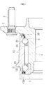
- the rolling bearing device for a wheel includes an inner ring member 1 (which will also be called “hub wheel"), an outer ring member 10, and rolling elements 20, 21 that are respectively arranged in two rows.
- the rolling elements 20, 21 are rollably disposed respectively in two rows between the inner ring member 1 and the outer ring member 10, and are retained by cages 25, 26.
- the inner ring member 1 has a hub spindle 4, and a flange 3 formed integrally with the hub spindle 4.
- the flange 3 extends radially outward from an outer periphery of the hub spindle 4 near one end thereof.
- Multiple hub bolts 2 for fastening the wheel to the flange 3 are provided at given intervals in the flange 3.
- an annular space is formed between an inner-ring shoulder portion of an inner-ring raceway surface 6 on one side (closer to the flange 3) of the inner ring member 1, and an inner periphery of one end portion of the outer ring member 10 which is opposed to the outer periphery of the inner-ring shoulder portion, and a seal member 30 for sealing the annular space is mounted in the annular space.
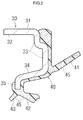
- the seal member 30 includes a core metal 31 and a molded seal 40.
- the core metal 31 includes a cylindrical portion 32, an annular portion 33, a tapered portion 34, and a radially inner end portion 35.
- the cylindrical portion 32 is press-fitted in and fixed to an inner periphery of one end portion of the outer ring member 10.
- the annular portion 33 is formed through a bending process so as to extend radially inward from one end of the cylindrical portion 32.
- the tapered portion 34 is formed through a bending process so as to extend obliquely and inward from a radially inner end of the annular portion 33.
- the radially inner end portion 35 is formed through a bending process so as to extend radially inward from a distal end of the tapered portion 34.
- the molded seal 40 is bonded to one side face of the core metal 31, i.e., the outer surfaces of the annular portion 33, tapered portion 34, and radially inner end portion 35, so as to form an integral structure.
- the molded seal 40 includes a lip 41 that is in sliding contact with the vicinity of a base end portion of the flange 3 of the inner ring member 1, and lips 42, 43 that are in sliding contact with an outer periphery of an inner-ring shoulder portion.
- the molded seal 40 is produced by a production method as described below, and its surface including the lips 41, 42, 43 is formed with minute projections and recesses 45.
- the method of producing the seal member according to this embodiment includes a mixing step, a molding step, a particle removing step, and a joining step.
- a mixing step as shown in FIG. 4(A) , an elastic material 60, such as a rubber material or a soft resin material, in a molten state is fed to the upstream side of a clearance between a pair of rollers of a roller-type kneading device 71 as one example of kneading device, and fine particles 61 are fed from a particle charging device 75 into the elastic material 60.
- an elastic material 60 such as a rubber material or a soft resin material
- the elastic material 60 and the fine particles 61 are mixed together by the roller-type kneading device 71, so as to form a mixed material 62.
- water-soluble particles e.g., salt, sugar, etc.
- a screw-type kneading device may be used in place of the roller-type kneading device 71.
- the mixed material 62 is charged into a cavity formed between two molding dies 76, 77 that are placed in the open or closed position, as shown in FIG. 4(B) , so as to form an elastic molded piece 65 having a shape corresponding to that of the molded seal 40 of the seal member 30.
- the two molding dies 76, 77 are brought into the open position, and the elastic molded piece 65 is removed from the dies 76, 77.
- the elastic molded piece 65 is removed while the undercut portion of the molded piece 65 is elastically deformed.
- the fine particles 61 present on a surface of the elastic molded piece 65 are removed, so that the molded seal 40 is formed.
- the fine particles 61 are water-soluble particles; therefore, as shown in FIG. 4(C) , the elastic molded piece 65 is put into and washed in a wash tank 80 in which a wash liquid (such as hot water, warm water, or ambient temperature water) is stored. In this manner, the fine particles 61 present on the surface of the elastic molded piece 65 are dissolved and removed, so that the molded seal 40 having minute projections and recesses 45 on its surface is formed.
- a wash liquid such as hot water, warm water, or ambient temperature water
- the molded seal 40 is bonded integrally to one side face of the core metal 31, i.e., the outer surfaces of the annular portion 33, tapered portion 34 and radially inner end portion 35, with an adhesive or through cure adhesion, for example, to thus form the seal member 30, as shown in FIG. 4(D) .
- the method of producing the seal member according to this embodiment includes the above-described steps.
- the fine particles 61 present on the surface of the elastic molded piece 65 are removed.
- the molded seal 40 having minute projections and recesses 45 on its surface is easily produced.
- the molded seal 40 is joined (bonded) integrally to the core metal 31, so as to provide the seal member 30.
- the lips 41, 42, 43 of the molded seal 40 assure sealing performance, and the minute projections and recesses 45 formed on the sliding surfaces of the lips 41, 42, 43 serve to reduce the sliding resistance.
- the use of the water-soluble particles as the fine particles 61 makes it possible to dissolve the fine particles 61 present on the surface of the elastic molded piece 65 in the wash liquid (such as hot water, warm water, or ambient temperature water), and easily remove the fine particles 61. Consequently, the molded seal 40 is produced with improved efficiency, at reduced cost.
- the wash liquid such as hot water, warm water, or ambient temperature water
- a seal member 130 includes a core metal 131 and a molded seal 140, as shown in FIG. 5
- the molded seal 140 includes a lip 141 that is in sliding contact with an annular portion 152 of a slinger 150, and lips 142, 143 that are in sliding contact with an outer periphery of a cylindrical portion 151 of the slinger 150.
- a sealing device having the seal member 130 and the slinger 150 is disposed between a raceway shoulder portion of an inner ring body 5 mounted on an end portion of the hub spindle 4 of the inner ring member 1 of the rolling bearing device for a wheel, and an inner periphery of an end portion of the outer ring member 10, as shown in FIG. 1 .
- the seal member 30 (130) includes the core metal 31 (131) and the molded seal 40 (140) in the illustrated embodiment, the seal member may consist solely of a molded seal.
- the use of the water-soluble particles makes it possible to dissolve the fine particles present on the surface of the elastic molded piece in the wash liquid (such as hot water or warm water), and easily remove the fine particles, thus effectively improving the productivity and reducing the cost.
- the wash liquid such as hot water or warm water
Landscapes
- Engineering & Computer Science (AREA)
- General Engineering & Computer Science (AREA)
- Mechanical Engineering (AREA)
- Manufacturing & Machinery (AREA)
- Chemical & Material Sciences (AREA)
- Dispersion Chemistry (AREA)
- Sealing Of Bearings (AREA)
- Sealing With Elastic Sealing Lips (AREA)
- Rolling Contact Bearings (AREA)
- Injection Moulding Of Plastics Or The Like (AREA)
Abstract
Description
- The invention relates to a method of producing a seal member.
- A known example of a seal member used in a rolling bearing device for a wheel, for example, for sealing an annular space between an inner ring member and an outer ring member includes a fixed portion fixed to an inner periphery of the outer ring member, and a lip that is in sliding contact with the vicinity of a raceway shoulder portion of the inner ring member.
In the seal member as described above, if two or more lips are formed, or the elastic force of the lip(s) is increased so as to enhance the sealing performance, the sliding resistance increases, resulting in an adverse influence on the fuel efficiency and significant wear of the lip(s).
Under the circumstances, a sealed rolling bearing as disclosed in Japanese Patent Application Publication No.2004-19779 JP 2004-19779 A
In the sealed rolling bearing containing a lubricant, as disclosed inJP 2004-19779 A
To form the minute projections and recesses on/in the surface of the lip of the seal member in the rolling bearing ofJP 2004-19779A - It is possible to reduce the sliding resistance by forming the minute projections and recesses on/in the surface of the lip of the seal member, as disclosed in
JP 2004-19779 A
However, a large number of pimple-like protrusions have to be formed on the molding surface of the molding die (mold), so as to form the minute projections and recesses on/in the surface of the lip; therefore, the cost of production of the molding die is increased, and the manufacturing cost of the seal member is increased accordingly. - It is an object of the invention to provide a method of producing a seal member, by which a seal member that is able to reduce sliding resistance while assuring sealing performance is easily produced.
- A method of producing a seal member according to an aspect of the invention includes: mixing an elastic material and fine particles using a kneading device, so as to form a mixed material; charging the mixed material into a molding die, and forming an elastic molded piece having a shape corresponding to that of a molded seal of the seal member; and removing the fine particles present on a surface of the elastic molded piece, so as to form the molded seal.
- The foregoing and further features and advantages of the invention will become apparent from the following description of example embodiments with reference to the accompanying drawings, wherein like numerals are used to represent like elements and wherein:
-
FIG. 1 is a vertical cross-sectional view showing a state in which a seal member according to an embodiment of the invention is mounted in a rolling bearing device for a wheel; -
FIG. 2 is a vertical cross-sectional view showing, in enlargement, the seal member shown inFIG. 1 ; -
FIG. 3 is a vertical cross-sectional view showing, in enlargement, lips of the seal member shown inFIG. 2 ; -
FIG. 4 illustrates respective steps of a method of producing a seal member according to the embodiment of the invention, whereinFIG. 4(A) is an explanatory view showing a mixing step,FIG. 4(B) is an explanatory view showing a molding step of forming an elastic molded piece,FIG. 4(C) is an explanatory view showing a particle removing step of removing fine particles present on a surface of the elastic molded piece so as to form a molded seal, andFIG. 4(D) is an explanatory view showing a joining step of joining the molded seal from which the fine particles are removed, and a core metal, into an integral structure; and -
FIG. 5 is a vertical cross-sectional view showing another seal member produced by the method of producing the seal member according to the invention. - First, a rolling bearing device for a wheel on which a seal member produced by a method of producing a seal member according to an embodiment of the invention is mounted will be described.
As shown inFIG. 1 , the rolling bearing device for a wheel includes an inner ring member 1 (which will also be called "hub wheel"), anouter ring member 10, androlling elements rolling elements inner ring member 1 and theouter ring member 10, and are retained bycages inner ring member 1 has ahub spindle 4, and aflange 3 formed integrally with thehub spindle 4. Theflange 3 extends radially outward from an outer periphery of thehub spindle 4 near one end thereof. Multiple hub bolts 2 for fastening the wheel to theflange 3 are provided at given intervals in theflange 3. - As shown in
FIG. 1 , an annular space is formed between an inner-ring shoulder portion of an inner-ring raceway surface 6 on one side (closer to the flange 3) of theinner ring member 1, and an inner periphery of one end portion of theouter ring member 10 which is opposed to the outer periphery of the inner-ring shoulder portion, and aseal member 30 for sealing the annular space is mounted in the annular space.
As shown inFIG. 2 , theseal member 30 includes acore metal 31 and a moldedseal 40.
Thecore metal 31 includes acylindrical portion 32, anannular portion 33, atapered portion 34, and a radiallyinner end portion 35. Thecylindrical portion 32 is press-fitted in and fixed to an inner periphery of one end portion of theouter ring member 10. Theannular portion 33 is formed through a bending process so as to extend radially inward from one end of thecylindrical portion 32. Thetapered portion 34 is formed through a bending process so as to extend obliquely and inward from a radially inner end of theannular portion 33. The radiallyinner end portion 35 is formed through a bending process so as to extend radially inward from a distal end of thetapered portion 34.
The moldedseal 40 is bonded to one side face of thecore metal 31, i.e., the outer surfaces of theannular portion 33,tapered portion 34, and radiallyinner end portion 35, so as to form an integral structure.
The moldedseal 40 includes alip 41 that is in sliding contact with the vicinity of a base end portion of theflange 3 of theinner ring member 1, andlips
The moldedseal 40 is produced by a production method as described below, and its surface including thelips recesses 45. - Next, the method of producing the seal member according to one embodiment of the invention will be described with reference to
FIG. 4(A) through FIG. 4(D) .
The method of producing the seal member according to this embodiment includes a mixing step, a molding step, a particle removing step, and a joining step.
First, in the mixing step, as shown inFIG. 4(A) , anelastic material 60, such as a rubber material or a soft resin material, in a molten state is fed to the upstream side of a clearance between a pair of rollers of a roller-type kneading device 71 as one example of kneading device, andfine particles 61 are fed from aparticle charging device 75 into theelastic material 60.
Then, theelastic material 60 and thefine particles 61 are mixed together by the roller-type kneading device 71, so as to form a mixedmaterial 62.
In this embodiment, water-soluble particles (e.g., salt, sugar, etc.) are used as thefine particles 61.
As the kneading device, a screw-type kneading device may be used in place of the roller-type kneading device 71. - Subsequently, in the molding step, the
mixed material 62 is charged into a cavity formed between two molding dies 76, 77 that are placed in the open or closed position, as shown inFIG. 4(B) , so as to form an elastic moldedpiece 65 having a shape corresponding to that of themolded seal 40 of theseal member 30.
Then, the two molding dies 76, 77 are brought into the open position, and the elastic moldedpiece 65 is removed from thedies piece 65, the elastic moldedpiece 65 is removed while the undercut portion of themolded piece 65 is elastically deformed. - Subsequently, in the particle removing step, the
fine particles 61 present on a surface of the elastic moldedpiece 65 are removed, so that the moldedseal 40 is formed.
In this embodiment, thefine particles 61 are water-soluble particles; therefore, as shown inFIG. 4(C) , the elastic moldedpiece 65 is put into and washed in awash tank 80 in which a wash liquid (such as hot water, warm water, or ambient temperature water) is stored.
In this manner, thefine particles 61 present on the surface of the elastic moldedpiece 65 are dissolved and removed, so that the moldedseal 40 having minute projections and recesses 45 on its surface is formed. - Finally, in the joining step, the
molded seal 40 is bonded integrally to one side face of thecore metal 31, i.e., the outer surfaces of theannular portion 33,tapered portion 34 and radiallyinner end portion 35, with an adhesive or through cure adhesion, for example, to thus form theseal member 30, as shown inFIG. 4(D) . - The method of producing the seal member according to this embodiment includes the above-described steps.
Thus, after the mixedmaterial 62 of theelastic material 60 and thefine particles 61 are charged into the molding dies 76, 77, and the elastic moldedpiece 65 of which the shape corresponds to that of themolded seal 40 is formed, thefine particles 61 present on the surface of the elastic moldedpiece 65 are removed. In this manner, the moldedseal 40 having minute projections andrecesses 45 on its surface is easily produced.
Then, the moldedseal 40 is joined (bonded) integrally to thecore metal 31, so as to provide theseal member 30.
In theseal member 30 produced as described above, thelips seal 40 assure sealing performance, and the minute projections andrecesses 45 formed on the sliding surfaces of thelips - Also, in this embodiment, the use of the water-soluble particles as the
fine particles 61 makes it possible to dissolve thefine particles 61 present on the surface of the elastic moldedpiece 65 in the wash liquid (such as hot water, warm water, or ambient temperature water), and easily remove thefine particles 61. Consequently, the moldedseal 40 is produced with improved efficiency, at reduced cost. - It is to be understood that this invention is not limited to the illustrated embodiment, but may be embodied in various forms, without departing from the principle of the invention.
For example, this invention may also be implemented in the case where aseal member 130 includes acore metal 131 and a moldedseal 140, as shown inFIG. 5 , and the moldedseal 140 includes alip 141 that is in sliding contact with anannular portion 152 of aslinger 150, andlips cylindrical portion 151 of theslinger 150.
For example, a sealing device having theseal member 130 and theslinger 150 is disposed between a raceway shoulder portion of aninner ring body 5 mounted on an end portion of thehub spindle 4 of theinner ring member 1 of the rolling bearing device for a wheel, and an inner periphery of an end portion of theouter ring member 10, as shown inFIG. 1 .
While the seal member 30 (130) includes the core metal 31 (131) and the molded seal 40 (140) in the illustrated embodiment, the seal member may consist solely of a molded seal. - According to the present invention, the use of the water-soluble particles makes it possible to dissolve the fine particles present on the surface of the elastic molded piece in the wash liquid (such as hot water or warm water), and easily remove the fine particles, thus effectively improving the productivity and reducing the cost.
Claims (2)
- A method of producing a seal member, characterized by comprising:mixing an elastic material and fine particles using a kneading device, so as to form a mixed material;charging the mixed material into a molding die, and forming an elastic molded piece having a shape corresponding to that of a molded seal of the seal member; andremoving the fine particles present on a surface of the elastic molded piece, so as to form the molded seal.
- The method according to claim 1, wherein:water-soluble particles are used as the fine particles; andthe elastic molded piece is washed with a wash liquid, so that the fine particles present on the surface of the elastic molded piece are dissolved to be removed.
Applications Claiming Priority (1)
| Application Number | Priority Date | Filing Date | Title |
|---|---|---|---|
| JP2011085182A JP2012219889A (en) | 2011-04-07 | 2011-04-07 | Method of producing seal member |
Publications (1)
| Publication Number | Publication Date |
|---|---|
| EP2508779A1 true EP2508779A1 (en) | 2012-10-10 |
Family
ID=45936828
Family Applications (1)
| Application Number | Title | Priority Date | Filing Date |
|---|---|---|---|
| EP12160147A Withdrawn EP2508779A1 (en) | 2011-04-07 | 2012-03-19 | Method of producing a seal member |
Country Status (4)
| Country | Link |
|---|---|
| US (1) | US20120256342A1 (en) |
| EP (1) | EP2508779A1 (en) |
| JP (1) | JP2012219889A (en) |
| CN (1) | CN102734332A (en) |
Families Citing this family (2)
| Publication number | Priority date | Publication date | Assignee | Title |
|---|---|---|---|---|
| US9581199B2 (en) * | 2012-10-25 | 2017-02-28 | Ntn Corporation | Fulcrum bearing device for pulley arm |
| JP2015183747A (en) * | 2014-03-24 | 2015-10-22 | 株式会社ジェイテクト | wheel bearing device |
Citations (2)
| Publication number | Priority date | Publication date | Assignee | Title |
|---|---|---|---|---|
| JPH0942461A (en) * | 1995-08-01 | 1997-02-14 | Koyo Seiko Co Ltd | Oil seal and its manufacturing method |
| JP2004019779A (en) | 2002-06-17 | 2004-01-22 | Nsk Ltd | Sealed rolling bearing and method for manufacturing sealing plate thereof |
Family Cites Families (5)
| Publication number | Priority date | Publication date | Assignee | Title |
|---|---|---|---|---|
| US3062760A (en) * | 1959-10-06 | 1962-11-06 | Electric Storage Battery Co | Method of producing a microporous polymeric resin |
| US3956020A (en) * | 1968-10-31 | 1976-05-11 | General Electric Company | Ultrafine porous polymer articles |
| GB1412983A (en) * | 1971-11-30 | 1975-11-05 | Debell & Richardson | Method of producing porous plastic materials |
| US4657544A (en) * | 1984-04-18 | 1987-04-14 | Cordis Corporation | Cardiovascular graft and method of forming same |
| JP5033311B2 (en) * | 2005-03-04 | 2012-09-26 | Ntn株式会社 | Resin oil body and method |
-
2011
- 2011-04-07 JP JP2011085182A patent/JP2012219889A/en not_active Withdrawn
-
2012
- 2012-03-15 US US13/421,472 patent/US20120256342A1/en not_active Abandoned
- 2012-03-19 EP EP12160147A patent/EP2508779A1/en not_active Withdrawn
- 2012-04-01 CN CN2012100965034A patent/CN102734332A/en active Pending
Patent Citations (2)
| Publication number | Priority date | Publication date | Assignee | Title |
|---|---|---|---|---|
| JPH0942461A (en) * | 1995-08-01 | 1997-02-14 | Koyo Seiko Co Ltd | Oil seal and its manufacturing method |
| JP2004019779A (en) | 2002-06-17 | 2004-01-22 | Nsk Ltd | Sealed rolling bearing and method for manufacturing sealing plate thereof |
Also Published As
| Publication number | Publication date |
|---|---|
| CN102734332A (en) | 2012-10-17 |
| JP2012219889A (en) | 2012-11-12 |
| US20120256342A1 (en) | 2012-10-11 |
Similar Documents
| Publication | Publication Date | Title |
|---|---|---|
| US9748551B2 (en) | Battery parts having retaining and sealing features and associated methods of manufacture and use | |
| CN105909680B (en) | Insert molded article, method for manufacturing protective cover, and method for manufacturing bearing device | |
| EP3575640A1 (en) | Compression vulcanization molding mold for rolling bearing seal, and method for manufacturing rolling bearing seal | |
| US20130148919A1 (en) | Rolling bearing and manufacturing method thereof | |
| US20120256342A1 (en) | Method of producing seal member | |
| CN111486178B (en) | Method for manufacturing slinger for sealing device for rotation and sealing device for rotation | |
| JP2019094976A (en) | Electric corrosion prevention bearing | |
| US20180354171A1 (en) | Production method for cover | |
| CN104797834B (en) | Crown retainer | |
| US9895736B2 (en) | Cover manufacturing method and press die used in same | |
| US10003066B2 (en) | Connecting pole for a rechargeable battery, rechargeable battery housing and machine for producing a connecting pole | |
| CN103925300B (en) | A kind of assembly method using the deep groove ball bearing of soft engineering plastic cage | |
| JP2012183562A (en) | Method of manufacturing shaft member for wheel rolling bearing device | |
| CN203023270U (en) | Insulated bearing with insulated ferrule | |
| CN204253599U (en) | A kind of automobile hub bearing of novel seal groove buckle structure | |
| JP2013024393A (en) | Apparatus and method for attaching wheel bearing device | |
| JP6253191B2 (en) | Manufacturing method of molding dies and composite products | |
| JP2011246022A (en) | Method for press-forming end-face tooth row | |
| CN203067561U (en) | Pressure welding structure of portal crane bearing support | |
| JP2017223253A (en) | Manufacturing method of wheel bearing device | |
| JP5901919B2 (en) | Roller bearing cage | |
| JP4032524B2 (en) | Manufacturing method of sealing device | |
| CN206221664U (en) | Sealing structure | |
| JP2015161334A (en) | rotary shaft seal | |
| CN205165704U (en) | An interior T shape ring blank is upset and is crowded fashioned mould |
Legal Events
| Date | Code | Title | Description |
|---|---|---|---|
| PUAI | Public reference made under article 153(3) epc to a published international application that has entered the european phase |
Free format text: ORIGINAL CODE: 0009012 |
|
| AK | Designated contracting states |
Kind code of ref document: A1 Designated state(s): AL AT BE BG CH CY CZ DE DK EE ES FI FR GB GR HR HU IE IS IT LI LT LU LV MC MK MT NL NO PL PT RO RS SE SI SK SM TR |
|
| AX | Request for extension of the european patent |
Extension state: BA ME |
|
| 17P | Request for examination filed |
Effective date: 20130410 |
|
| GRAP | Despatch of communication of intention to grant a patent |
Free format text: ORIGINAL CODE: EPIDOSNIGR1 |
|
| RIC1 | Information provided on ipc code assigned before grant |
Ipc: F16J 15/32 20060101AFI20140114BHEP |
|
| RAP1 | Party data changed (applicant data changed or rights of an application transferred) |
Owner name: JTEKT CORPORATION |
|
| RIN1 | Information on inventor provided before grant (corrected) |
Inventor name: MASUDA, YOSHINORI |
|
| INTG | Intention to grant announced |
Effective date: 20140206 |
|
| GRAP | Despatch of communication of intention to grant a patent |
Free format text: ORIGINAL CODE: EPIDOSNIGR1 |
|
| INTG | Intention to grant announced |
Effective date: 20140506 |
|
| GRAJ | Information related to disapproval of communication of intention to grant by the applicant or resumption of examination proceedings by the epo deleted |
Free format text: ORIGINAL CODE: EPIDOSDIGR1 |
|
| GRAP | Despatch of communication of intention to grant a patent |
Free format text: ORIGINAL CODE: EPIDOSNIGR1 |
|
| GRAJ | Information related to disapproval of communication of intention to grant by the applicant or resumption of examination proceedings by the epo deleted |
Free format text: ORIGINAL CODE: EPIDOSDIGR1 |
|
| GRAP | Despatch of communication of intention to grant a patent |
Free format text: ORIGINAL CODE: EPIDOSNIGR1 |
|
| INTG | Intention to grant announced |
Effective date: 20140626 |
|
| INTG | Intention to grant announced |
Effective date: 20140721 |
|
| STAA | Information on the status of an ep patent application or granted ep patent |
Free format text: STATUS: THE APPLICATION IS DEEMED TO BE WITHDRAWN |
|
| 18D | Application deemed to be withdrawn |
Effective date: 20141202 |