EP2508444A1 - Carrier for articles - Google Patents
Carrier for articles Download PDFInfo
- Publication number
- EP2508444A1 EP2508444A1 EP12163332A EP12163332A EP2508444A1 EP 2508444 A1 EP2508444 A1 EP 2508444A1 EP 12163332 A EP12163332 A EP 12163332A EP 12163332 A EP12163332 A EP 12163332A EP 2508444 A1 EP2508444 A1 EP 2508444A1
- Authority
- EP
- European Patent Office
- Prior art keywords
- carrier
- panel
- handle
- panels
- base
- Prior art date
- Legal status (The legal status is an assumption and is not a legal conclusion. Google has not performed a legal analysis and makes no representation as to the accuracy of the status listed.)
- Withdrawn
Links
- 239000002131 composite material Substances 0.000 claims description 16
- 230000014759 maintenance of location Effects 0.000 description 43
- 210000003739 neck Anatomy 0.000 description 33
- 238000005192 partition Methods 0.000 description 30
- 239000003292 glue Substances 0.000 description 28
- 235000013361 beverage Nutrition 0.000 description 11
- 238000000034 method Methods 0.000 description 11
- 239000000969 carrier Substances 0.000 description 10
- 239000000463 material Substances 0.000 description 10
- 238000010276 construction Methods 0.000 description 9
- 239000000853 adhesive Substances 0.000 description 7
- 230000001070 adhesive effect Effects 0.000 description 7
- 239000011521 glass Substances 0.000 description 6
- 239000011087 paperboard Substances 0.000 description 6
- 239000000758 substrate Substances 0.000 description 6
- 238000004806 packaging method and process Methods 0.000 description 5
- 229920003023 plastic Polymers 0.000 description 5
- 239000013049 sediment Substances 0.000 description 5
- 238000000926 separation method Methods 0.000 description 5
- 238000012986 modification Methods 0.000 description 3
- 230000004048 modification Effects 0.000 description 3
- XLYOFNOQVPJJNP-UHFFFAOYSA-N water Substances O XLYOFNOQVPJJNP-UHFFFAOYSA-N 0.000 description 3
- 235000011389 fruit/vegetable juice Nutrition 0.000 description 2
- 239000007788 liquid Substances 0.000 description 2
- 238000004519 manufacturing process Methods 0.000 description 2
- 239000011159 matrix material Substances 0.000 description 2
- 230000008569 process Effects 0.000 description 2
- 230000000717 retained effect Effects 0.000 description 2
- 238000004026 adhesive bonding Methods 0.000 description 1
- XAGFODPZIPBFFR-UHFFFAOYSA-N aluminium Chemical compound [Al] XAGFODPZIPBFFR-UHFFFAOYSA-N 0.000 description 1
- 229910052782 aluminium Inorganic materials 0.000 description 1
- 230000004888 barrier function Effects 0.000 description 1
- 230000009286 beneficial effect Effects 0.000 description 1
- 230000008901 benefit Effects 0.000 description 1
- 230000015572 biosynthetic process Effects 0.000 description 1
- 239000012876 carrier material Substances 0.000 description 1
- 239000000470 constituent Substances 0.000 description 1
- -1 corrugated board Substances 0.000 description 1
- 238000001514 detection method Methods 0.000 description 1
- 235000015203 fruit juice Nutrition 0.000 description 1
- 230000005484 gravity Effects 0.000 description 1
- 239000012943 hotmelt Substances 0.000 description 1
- 230000001737 promoting effect Effects 0.000 description 1
- 239000003643 water by type Substances 0.000 description 1
Images





Classifications
-
- B—PERFORMING OPERATIONS; TRANSPORTING
- B65—CONVEYING; PACKING; STORING; HANDLING THIN OR FILAMENTARY MATERIAL
- B65D—CONTAINERS FOR STORAGE OR TRANSPORT OF ARTICLES OR MATERIALS, e.g. BAGS, BARRELS, BOTTLES, BOXES, CANS, CARTONS, CRATES, DRUMS, JARS, TANKS, HOPPERS, FORWARDING CONTAINERS; ACCESSORIES, CLOSURES, OR FITTINGS THEREFOR; PACKAGING ELEMENTS; PACKAGES
- B65D71/00—Bundles of articles held together by packaging elements for convenience of storage or transport, e.g. portable segregating carrier for plural receptacles such as beer cans or pop bottles; Bales of material
- B65D71/0003—Tray-like elements provided with handles, for storage or transport of several articles, e.g. bottles, tins, jars
- B65D71/0022—Tray-like elements provided with handles, for storage or transport of several articles, e.g. bottles, tins, jars formed by folding or erecting one blank, and provided with vertical partitions
-
- B—PERFORMING OPERATIONS; TRANSPORTING
- B65—CONVEYING; PACKING; STORING; HANDLING THIN OR FILAMENTARY MATERIAL
- B65D—CONTAINERS FOR STORAGE OR TRANSPORT OF ARTICLES OR MATERIALS, e.g. BAGS, BARRELS, BOTTLES, BOXES, CANS, CARTONS, CRATES, DRUMS, JARS, TANKS, HOPPERS, FORWARDING CONTAINERS; ACCESSORIES, CLOSURES, OR FITTINGS THEREFOR; PACKAGING ELEMENTS; PACKAGES
- B65D2571/00—Bundles of articles held together by packaging elements for convenience of storage or transport, e.g. portable segregating carrier for plural receptacles such as beer cans, pop bottles; Bales of material
- B65D2571/00123—Bundling wrappers or trays
- B65D2571/00129—Wrapper locking means
- B65D2571/00135—Wrapper locking means integral with the wrapper
- B65D2571/00141—Wrapper locking means integral with the wrapper glued
-
- B—PERFORMING OPERATIONS; TRANSPORTING
- B65—CONVEYING; PACKING; STORING; HANDLING THIN OR FILAMENTARY MATERIAL
- B65D—CONTAINERS FOR STORAGE OR TRANSPORT OF ARTICLES OR MATERIALS, e.g. BAGS, BARRELS, BOTTLES, BOXES, CANS, CARTONS, CRATES, DRUMS, JARS, TANKS, HOPPERS, FORWARDING CONTAINERS; ACCESSORIES, CLOSURES, OR FITTINGS THEREFOR; PACKAGING ELEMENTS; PACKAGES
- B65D2571/00—Bundles of articles held together by packaging elements for convenience of storage or transport, e.g. portable segregating carrier for plural receptacles such as beer cans, pop bottles; Bales of material
- B65D2571/00123—Bundling wrappers or trays
- B65D2571/00246—Locating elements for the contents
- B65D2571/00253—Locating elements for the contents integral with the wrapper
- B65D2571/00308—Locating elements for the contents integral with the wrapper consisting of inwardly bent panels or flaps
- B65D2571/00314—Locating elements for the contents integral with the wrapper consisting of inwardly bent panels or flaps with locating holes or cuts
-
- B—PERFORMING OPERATIONS; TRANSPORTING
- B65—CONVEYING; PACKING; STORING; HANDLING THIN OR FILAMENTARY MATERIAL
- B65D—CONTAINERS FOR STORAGE OR TRANSPORT OF ARTICLES OR MATERIALS, e.g. BAGS, BARRELS, BOTTLES, BOXES, CANS, CARTONS, CRATES, DRUMS, JARS, TANKS, HOPPERS, FORWARDING CONTAINERS; ACCESSORIES, CLOSURES, OR FITTINGS THEREFOR; PACKAGING ELEMENTS; PACKAGES
- B65D2571/00—Bundles of articles held together by packaging elements for convenience of storage or transport, e.g. portable segregating carrier for plural receptacles such as beer cans, pop bottles; Bales of material
- B65D2571/00123—Bundling wrappers or trays
- B65D2571/00333—Partitions, i.e. elements contacting a major part of each aarticle or extending across the whole length of the wrapper
- B65D2571/0037—Partitions, i.e. elements contacting a major part of each aarticle or extending across the whole length of the wrapper extending from at least a side wall
- B65D2571/00376—Squarings or the like
- B65D2571/00388—Two rows of more than two cells
-
- B—PERFORMING OPERATIONS; TRANSPORTING
- B65—CONVEYING; PACKING; STORING; HANDLING THIN OR FILAMENTARY MATERIAL
- B65D—CONTAINERS FOR STORAGE OR TRANSPORT OF ARTICLES OR MATERIALS, e.g. BAGS, BARRELS, BOTTLES, BOXES, CANS, CARTONS, CRATES, DRUMS, JARS, TANKS, HOPPERS, FORWARDING CONTAINERS; ACCESSORIES, CLOSURES, OR FITTINGS THEREFOR; PACKAGING ELEMENTS; PACKAGES
- B65D2571/00—Bundles of articles held together by packaging elements for convenience of storage or transport, e.g. portable segregating carrier for plural receptacles such as beer cans, pop bottles; Bales of material
- B65D2571/00123—Bundling wrappers or trays
- B65D2571/00432—Handles or suspending means
- B65D2571/00456—Handles or suspending means integral with the wrapper
- B65D2571/00475—Handles or suspending means integral with the wrapper and extending ion a substantially vertical plane
- B65D2571/00487—Handles or suspending means integral with the wrapper and extending ion a substantially vertical plane and formed integrally with a partition
-
- B—PERFORMING OPERATIONS; TRANSPORTING
- B65—CONVEYING; PACKING; STORING; HANDLING THIN OR FILAMENTARY MATERIAL
- B65D—CONTAINERS FOR STORAGE OR TRANSPORT OF ARTICLES OR MATERIALS, e.g. BAGS, BARRELS, BOTTLES, BOXES, CANS, CARTONS, CRATES, DRUMS, JARS, TANKS, HOPPERS, FORWARDING CONTAINERS; ACCESSORIES, CLOSURES, OR FITTINGS THEREFOR; PACKAGING ELEMENTS; PACKAGES
- B65D2571/00—Bundles of articles held together by packaging elements for convenience of storage or transport, e.g. portable segregating carrier for plural receptacles such as beer cans, pop bottles; Bales of material
- B65D2571/00123—Bundling wrappers or trays
- B65D2571/00648—Elements used to form the wrapper
- B65D2571/00654—Blanks
- B65D2571/0066—Blanks formed from one single sheet
-
- B—PERFORMING OPERATIONS; TRANSPORTING
- B65—CONVEYING; PACKING; STORING; HANDLING THIN OR FILAMENTARY MATERIAL
- B65D—CONTAINERS FOR STORAGE OR TRANSPORT OF ARTICLES OR MATERIALS, e.g. BAGS, BARRELS, BOTTLES, BOXES, CANS, CARTONS, CRATES, DRUMS, JARS, TANKS, HOPPERS, FORWARDING CONTAINERS; ACCESSORIES, CLOSURES, OR FITTINGS THEREFOR; PACKAGING ELEMENTS; PACKAGES
- B65D2571/00—Bundles of articles held together by packaging elements for convenience of storage or transport, e.g. portable segregating carrier for plural receptacles such as beer cans, pop bottles; Bales of material
- B65D2571/00123—Bundling wrappers or trays
- B65D2571/00648—Elements used to form the wrapper
- B65D2571/00654—Blanks
- B65D2571/00666—Blanks formed from two or more sheets
-
- B—PERFORMING OPERATIONS; TRANSPORTING
- B65—CONVEYING; PACKING; STORING; HANDLING THIN OR FILAMENTARY MATERIAL
- B65D—CONTAINERS FOR STORAGE OR TRANSPORT OF ARTICLES OR MATERIALS, e.g. BAGS, BARRELS, BOTTLES, BOXES, CANS, CARTONS, CRATES, DRUMS, JARS, TANKS, HOPPERS, FORWARDING CONTAINERS; ACCESSORIES, CLOSURES, OR FITTINGS THEREFOR; PACKAGING ELEMENTS; PACKAGES
- B65D2571/00—Bundles of articles held together by packaging elements for convenience of storage or transport, e.g. portable segregating carrier for plural receptacles such as beer cans, pop bottles; Bales of material
- B65D2571/00123—Bundling wrappers or trays
- B65D2571/00709—Shape of the formed wrapper, i.e. shape of each formed element if the wrapper is made from more than one element
- B65D2571/00722—Shape of the formed wrapper, i.e. shape of each formed element if the wrapper is made from more than one element tubular with end walls, e.g. walls not extending on the whole end surface
- B65D2571/00728—Shape of the formed wrapper, i.e. shape of each formed element if the wrapper is made from more than one element tubular with end walls, e.g. walls not extending on the whole end surface the end walls being closed by gluing
-
- B—PERFORMING OPERATIONS; TRANSPORTING
- B65—CONVEYING; PACKING; STORING; HANDLING THIN OR FILAMENTARY MATERIAL
- B65D—CONTAINERS FOR STORAGE OR TRANSPORT OF ARTICLES OR MATERIALS, e.g. BAGS, BARRELS, BOTTLES, BOXES, CANS, CARTONS, CRATES, DRUMS, JARS, TANKS, HOPPERS, FORWARDING CONTAINERS; ACCESSORIES, CLOSURES, OR FITTINGS THEREFOR; PACKAGING ELEMENTS; PACKAGES
- B65D2571/00—Bundles of articles held together by packaging elements for convenience of storage or transport, e.g. portable segregating carrier for plural receptacles such as beer cans, pop bottles; Bales of material
- B65D2571/00123—Bundling wrappers or trays
- B65D2571/00709—Shape of the formed wrapper, i.e. shape of each formed element if the wrapper is made from more than one element
- B65D2571/0079—U-shaped
Definitions
- This invention relates generally to carriers and, more particularly, to carriers for articles, more specifically, but not necessarily exclusively, to carriers for bottles.
- Carriers for articles such as beverage bottles are useful to enable consumers to transport and store the articles.
- Such carriers may be designed to expose articles, but the carrier may obstruct the articles and may also provide have limited space for displaying information such as advertising copy and graphics, because to securely enclose the articles, much of the surface area of the typical carrier faces inward.
- the typical six-pack carrier includes the same amount of inside surface as outside surface, and bottles usually obstruct the view of copy on the handle panel. It is particularly challenging to provide carriers that work in concert with the aesthetics of high-end articles, such as bottles for so-called designer water brands.
- transparent articles may reveal the unattractive reverse side of the carrier, which is often brown paperboard.
- beverages for example fruit juices, which have a fleshy sediment, when stored can become separated into a watery first liquid and a thicker, second sediment.
- a consumer is required to mix the beverage prior to opening.
- a package that facilitates the mixing of two-part beverages, such as flavoured waters and juices as examples, would be advantageous.
- the present invention overcomes the shortcomings of the prior art by providing, in one aspect, a carrier that is configured to maximize the surface area that is available for displaying information, while otherwise promoting the aesthetics of the articles substantially without revealing the reverse side of the carrier material that need not be attractive so as to bear information or graphics, or to otherwise provide an aesthetic backdrop for a transparent article.
- the carrier is also configured to easily and securely engage articles during loading and to provide a structure that supports articles well when the carrier is carried.
- the carrier is also tamper resistant and tamper evident.
- another aspect of the invention provides a carrier for bottles disposed in an inverted configuration.
- a carrier for securing multiple articles each having a base and a top is formed to define a composite handle and central wall that extends vertically between a pair of cantilevered top securing structures and between a pair of base securing structures that stabilize the respective tops and bases of cylindrical articles such as beverage bottles that are positioned along each side of the central wall.
- the central wall is formed as the composite of at least two central panels and extends between two rows of three bottles, although any number of articles may be retained in the carrier.
- the composite handle extends upward from the central wall, and is formed from at least two handle panels, at least one of which is contiguous to one of the central panels that define the composite central wall.
- the central wall is a strong composite that can support the articles from lateral movement, and together with the composite handle, provides primary weight bearing capacity of the carrier.
- the handle extends upward, and may extend adjacent either the base securing structures or the top securing structures, as the cylindrical articles may be carried upright or upside down.
- the top securing structures retain the top of each cylindrical article by engaging a small part of the uppermost portion, while minimizing obstruction of the remainder of the cylindrical article.
- the top securing structures may engage a cap or other uppermost portion of a beverage bottle, while exposing the shoulder and midsection of the bottle.
- the base securing structures include heel panels that include encircling strips that retain the bases of cylindrical articles, such as the heels of beverage bottles.
- substantially all outside surfaces of the carrier are formed from the art side of a suitable substrate, such as the laminated, bleached and/or coated side of a paperboard substrate.
- the carrier may be formed by securing a pair of carrier parts together such that substantially all of the exposed surfaces of each carrier part are formed from the art side surface of a blank that forms the carrier part.
- the top securing structures each include a tubular structure and one or more neck receiving apertures that define a yoke panel. The yoke panel functions to restrain the necks or other uppermost portions of each article in substantially fixed relation to one another, thereby maintaining optimal spacing between the articles while retaining each article in the carrier.
- Each neck receiving aperture includes resistive tabs disposed, at least, along part of the periphery of the neck receiving aperture so as to be configured to resist the undesired movement of an article in a direction that is not obstructed by the central wall or by other articles, while allowing intentional removal of the article when desired.
- the cap or other uppermost portion of each article may be received in a neck receiving aperture, and thus, the uppermost portion may extend into the tubular structure.
- the neck receiving apertures, resistive tabs, and heel panels create a tamper resistant and tamper evident enclosure that leaves the majority of each article in view of the consumer.
- the handle extends adjacent to the top securing structures at the top of the carrier and the carrier is configured to rest on the base securing structures, with the articles positioned upright along both sides of the central wall.
- the cantilevered tubular top securing structures stabilize the upper portions of the articles, but are not configured to bear substantial weight. Rather, the weight of the articles is at least substantially borne by the handle via the central wall and by the bottom receiving structures.
- the top securing structures can be rotated upward to release the upper portions of the articles from neck receiving apertures.
- the handle extends adjacent to the base securing structures and the bottom of the carrier, and the carrier is configured to rest on the top securing structures, with the articles positioned upside down (in an inverted configuration) along both sides of the central wall.
- the cantilevered top securing structures stabilize the upper portions of the articles, and cooperate with one another and with the handle to bear the weight of the articles, although some deformation may occur when the carrier is lifted.
- Heel panels define encircling strips that enable the base securing structures to retain the bottoms of the articles, and have sufficient width to prevent escape even if the top securing structures deform during carrying.
- a carrier for securing one or more articles having a base and a top, the carrier comprising:
- the term carrier refers, for the non-limiting purpose of illustrating the various features of the invention, to a container for engaging, carrying, and dispensing articles, such as clear plastic bottles.
- teachings of the invention can be applied to various containers, which may or may not be tapered and/or cylindrical.
- Other exemplary articles include metallic or glass bottles, aluminum cans, bowling pins, candles, and the like.
- neck refers to a portion of a container adjacent an opening through which the container can dispense its contents. Typically, the opening is capped.
- the neck of a container may be, but is not necessarily, tapered with respect to a body of the article.
- the term “heel” or base refers to the portion of a beverage container (e.g., a bottle) that is opposite the opening. Typically, the article rests on its base.
- the body the primary content containing portion of the container
- the body is tapered or curves at its base (the support surface of the container).
- a carrier 190 is formed from a pair of blanks 100.
- the inside surface of the blank 100 is shown and the opposite side (not shown) of the blank 100 is its outside surface.
- the outside surface is used as its art side, which may bear printed product information, decorative designs, and brand specific indicia, such as logos, trademarks and associated copy. Either or both the inside and outside surface may be laminated or otherwise treated to make the carrier water-resistant, more durable, or to insulate the contents of the carrier.
- One advantage of the carrier 190 described in further detail below is that substantially all of the exposed surfaces of the carrier 190 are formed from the outside surface of the blanks 100.
- substantially all of the exposed surfaces of the carrier 190 can be used to display printed matter, and the often less attractive inside surface opposite the art side is at least largely obscured. This is useful when used with transparent plastic or glass bottles having substantially clear contents (such as water) since the bottles and their contents do not substantially obstruct the exposed inside surfaces of the carrier.
- the blank 100 is formed from a sheet of suitable substrate.
- suitable substrate includes all manner of foldable sheet material such as paperboard, corrugated board, cardboard, plastic, combinations thereof, and the like.
- a pair of the unitary blanks 100 is used to form the carrier 190.
- one or other numbers of blanks may be employed, for example, to provide the carrier structure described in more detail below.
- the blank 100 is configured to form part of a carrier for packaging an exemplary arrangement of exemplary articles 182.
- the arrangement is a matrix including rows and columns such as a 2x3 arrangement of articles 182.
- the blank can be alternatively configured to form a carrier for packaging other articles and/or different arrangements of articles.
- the blank 100 includes a series of panels that at least partially define a handle 192, top and base securing structures 194, 196, and a central wall of the carrier 190.
- the panels are aligned along a longitudinal axis of the blank 100 and are hingedly connected one to the next along fold lines that extend transversely with respect to the longitudinal axis.
- fold line refers to all manner of lines that define hinge features of the blank, facilitate folding portions of the blank with respect to one another, or otherwise indicate optimal panel folding locations for the blank.
- a fold line is typically a scored line, an embossed line, or a debossed line.
- severed line refers to all manner of lines that facilitate separating portions of the substrate from one another or that indicate optimal separation locations. Severance lines may be frangible or otherwise weakened lines, tear lines, cut lines, or slits.
- severance lines and fold lines can each include elements that are formed in the substrate of the blank including perforations, a line of perforations, a line of short slits, a line of half-cuts, a single half-cut, a cut line, an interrupted cut line, slits, scores, any combination thereof, and the like.
- the elements can be dimensioned and arranged to provide the desired functionality.
- a line of perforations can be dimensioned or designed with degrees of weakness to define a fold line and/or a severance line.
- the line of perforations can be designed to facilitate folding and resist breaking, to facilitate folding and facilitate breaking with more effort, or to facilitate breaking with little effort.
- the panels include: an inner handle panel 102; an outer handle panel 106; a top panel 116; a cap panel 120; a yoke panel 130; a central panel 134; a rear base panel 138; a front base panel 142; an inner heel panel 146; and an outer heel panel 150.
- the inner handle panel 102 is hingedly connected to the outer handle panel 106 along a fold line 104.
- the outer handle panel 106 is hingedly connected to the top panel 116 along fold line 112, and the top panel 116 is hingedly connected to the cap panel 120 along a fold line 118.
- the cap panel 120 is hingedly connected to the yoke panel 130 along a fold line 122 and the yoke panel 130 is hingedly connected to the central panel 134 along fold line 132.
- the central panel 134 is hingedly connected to the rear base panel 138 along fold line 136 and the rear base panel 138 is hingedly connected to the front base panel 142 along fold line 140.
- the front base panel 142 is hingedly connected to the inner heel panel 146 along fold line 144, and the inner heel panel 146 is hingedly connected to the outer heel panel 150 along the fold line 148.
- the fold line 140 is primarily used in collapsing the blank 100 prior to fully erecting the carrier 190, as will be described in more detail below.
- a handle flap 110 is hingedly connected to outer handle panel 106 along fold line 108.
- Side heel panels 154, 162 are hingedly connected to the opposed edges of the outer heel panel 150 along the fold lines 152, 160.
- the blank 100 further includes a heel panel tab 158 that is hingedly connected to the side heel panel 154 along a fold line 156 and a heel panel tab 166 that is hingedly connected to the side heel panel 162 along a fold line 164.
- the handle cushion panel 110 is hingedly connected to the outer handle panel 106 along a fold line 108.
- the illustrated yoke panel 130 includes neck retaining structures 124, 126, 128 each optionally including a number of resistance tabs 125, 127, 129 optionally disposed at least along part of the periphery of the neck retaining structures 124, 126, 128.
- the resistance tabs 125, 127, 129 are similar to one another but are disposed along different parts of the peripheries of the neck retaining structures as a function of the possible direction of movement of the associated article as is described in further detail below.
- Assembling a carrier part 180 from the blank 100 may be accomplished with the folding and securing operations as described herein.
- the operations can be performed by automatic erecting machinery and/or manually.
- the method of performing the assembling process is not limited to the exemplary method described herein. Particularly, the order of the steps can be altered according to manufacturing requirements, steps may be added or omitted, and the means for securing components to one another may vary.
- the surfaces of sheet material may be secured together by suitable means for securing including tape, staples, interlocking folds, VELCRO ® , glue or other adhesives, combinations thereof, and the like.
- the blank 100 is assembled to form a collapsed carrier part 180.
- the blank 100 is folded inwardly along the fold line 118, such that at least the inner handle panel 102 overlaps the central panel 134.
- the outer handle panel 106 is folded outwardly along the fold lines 112, 114 and the inner handle panel 102 is folded along the fold line 104 to overlay the outer handle panel 106.
- the inner handle panel 102 and the central panel 134 are secured to one another.
- the blank 100 is folded inwardly along fold lines 140, 148 so that the front base panel 142, inner heel panel 146, and outer heel panel 150 are collapsed beneath the central panel 134 and the rear base panel 138.
- the side heel panels 154, 162 are folded inwardly along fold lines 152, 160 to place the rear heel panels 158, 166 in flat face contact with the central panel 134.
- the rear heel panels 158, 166 and the central panel 134 are secured together to define an encircling strip comprising the outer heel panel 150 and side heel panels 154, 162.
- the carrier part 180 is formed in a collapsed condition.
- the non-artwork surface of central panels 134 of two of the collapsed carrier parts 180 are secured together (see FIG. 10 ) to form a carrier 190 in a collapsed condition.
- the illustrated carriers 190 are adapted to hold a group of similarly dimensioned articles, such as the clear plastic bottles 182, in a matrix arrangement of rows.
- each carrier part 180 holds a row of three bottles 182 such that the carrier 190 holds two rows of three bottles 182.
- Each bottle 182 is substantially cylindrical with a capped top end 184 and a base end 186.
- the bottle 182 includes a tapered neck 188 and cap at the top end 184.
- the carrier 190 can be erected from the collapsed condition.
- the front handle panels 102, 106 provide a handle 192; the top panel 116, the cap panel 120, and the yoke panel 130 provided a top securing structure 192; the rear base panel 138, the front base panel 142, the outer heel panel 150, and the side heel panels 154, 162 provide a base securing structure 196; and the central panels 134 provide opposing surfaces of a central wall 198.
- the handle 192 is adjacent the top securing structure 194 with the bottles 182 carried right side up (in other words, in a normal configuration).
- the carrier 190 can be partially erected and then loaded with bottles 182 prior to fully erecting the carrier 190 to hold the bottles 182 in place. More specifically, the carrier 190 is partially erected as follows. Two collapsed carrier parts 180 are secured to one another by adhering the inside (non-art) surface of each respective central panel 134 in a face contacting arrangement to form the composite central wall 198. The two central panels 134, one from each collapsed carrier part 180, can be secured to one another using any suitable means, including but not limited to, glue or other adhesives, tape, staples or other connectors, and the like.
- each of the base securing structures 196 are erected as a trough that is configured to receive the base ends 186 of bottles 182.
- the bottles 182 are loaded into the base securing structures 196 such that the base ends 186 are supported from below by the rear base panel 138 and the front base panel 142 and are laterally supported by the outer heel panel 150, the side heel panels 154, 162, and the central panel 134.
- the carrier 190 is fully erected when the top securing structure 194 is then lowered over the top ends 184 of the bottles 182.
- the top securing structure 194 is folded along fold lines 112, 118, 122, 132 such that the inner handle panel 102, the top panel 116, the cap panel 120, and the yoke panel 130 form a tubular structure and the top ends 184 are received in the tubular structure through the neck retaining structures 124, 126, 128.
- the resistance tabs 125, 127, 129 contact the neck 188 of the bottles 182 under the cap 184 (top end).
- the resistance tabs 125, 127, 129 resist the movement of the caps 184 through the neck retaining structures 124, 126, 128 and thus function to hold the top securing structure 194 over the top ends 184 of the bottles 182.
- the resistance tabs 125, 127, 129 are positioned along portions of the peripheries of the neck retaining structures 124, 126, 128 that are substantially opposite the fold line 132 or otherwise the central wall 198. In the illustrated embodiment, the resistance tabs 125, 127, 129 are positioned along different portions of the peripheries of respective neck receiving apertures 124, 126, 128 to resist the likely direction of movement of the bottles 182.
- the direction of movement of each bottle 182 is limited by the structure of the carrier 190 and the adjacent bottles 182. For example, lateral movement of the middle bottle 182 in each row is restricted by both the outer bottles 182 and the central wall 198.
- the neck retaining structure 126 allows some movement due to tolerances so the middle bottle 182 can have some movement normal to the central wall 198.
- the resistance tabs 127 are positioned opposite the central wall 198 to resist this movement and thus force the middle bottle 182 against the central wall 198.
- the resistance tabs 125, 129 force the outer bottles 182 against the middle bottle 182 and the central wall 198.
- the resistance tabs 125, 127, 129 force the bottles 182 inwardly and resist movement away from the carrier 190.
- each carrier part 180 of the carrier 190 When the handle 192 is engaged, the two carrier parts 180 of the carrier 190 are configured such that the forces applied by the weight of the bottles 182 in one carrier part 180 counter-balance forces applied by the weight of the bottles 182 in the other carrier part.
- the carrier parts 180 By engaging the handle 192, the carrier parts 180 are forced together, particularly at the lower end, by the weight of the bottles 182.
- each carrier part 180 is configured to provide structural support to the other carrier part 180.
- the carrier 190 is tamper evident and tamper resistant, in part because to remove a bottle 182, a user must dislodge the cap from a neck receiving aperture 124, 126, 128, which is difficult to do without deforming the top securing structure 194 or tearing the base securing structure 196.
- a user must dislodge the cap from a neck receiving aperture 124, 126, 128, which is difficult to do without deforming the top securing structure 194 or tearing the base securing structure 196.
- unwitting or intentional removal of a single item without detection is discouraged.
- a blank 200 of the second exemplary embodiment has features that are substantially the same as the blank 100 of the first exemplary embodiment.
- the first embodiment is configured for upright article packaging (also referred to as 'normal orientation'), whereas the second exemplary embodiment is configured for upside down (also referred to as 'inverted orientation') article packaging.
- the blank 200 includes: a handle panel 202; an outer central panel 210; a yoke panel 220; a cap panel 224; a bottom panel 228; an inner central panel 232; a rear top panel 258; a handle panel 259; a front top panel 260; and an outer heel panel 272.
- the handle panel 202 is hingedly connected to the outer central panel 210 along fold lines 208 and 209.
- the outer central panel 210 is hingedly connected to the yoke panel 220 along a fold line 212 and the yoke panel 220 is hingedly connected to the cap panel 224 along a fold line 222.
- the cap panel 224 is hingedly connected to the bottom panel 228 along a fold line 226 and the bottom panel 228 is hingedly connected to the inner central panel 232 along a fold line 230.
- the inner central panel 232 is hingedly connected to the top rear top panel 258 along fold line 250 and the rear top panel 258 is hingedly connected to the front top panel 260 along fold line 262.
- the front top panel 260 is hingedly connected to the outer heel panel 272 along fold line 270. Together, the front top panel 260 and rear top panel 258 define a top wall 268.
- the illustrated yoke panel 220 includes neck retaining structures 214, 216, 218 and resistance tabs 215, 217, 219.
- a handle panel 259 is hingedly connected to the inner central panel 232 along fold line 250.
- the handle panel 259 is defined in part in the front top panel 260 and in part in the rear top panel 258 along a severance line 264.
- an aperture 293 is revealed in the bottom support structure 296 adjacent the handle 292.
- a handle panel 206 is hingedly connected to the handle panel 202 along a fold line 204.
- the side heel panels 236, 244 are hingedly connected to the opposed edges of the inner central panel 232 along the fold lines 234, 242.
- a heel panel tab 240 is hingedly connected to the side heel panel 236 along a fold line 238 and a heel panel tab 248 is hingedly connected to the side heel panel 244 along a fold line 246.
- the blank 200 is assembled to form a carrier part 280 in a collapsed condition according to an exemplary method.
- the blank 200 is folded inwardly along the fold line 226 such that outer central panel 210 overlaps the inner central panel 232.
- the outer central panel 210 and the inner central panel 232 are secured together.
- the front top panel 260 is folded inwardly along the fold line 262 to overlap the handle panel 202 and rear top panel 258; the heel panel 272 overlaps the outer central panel 210. Referring to FIGs.
- the heel panel tabs 240, 248 are folded inwardly along fold lines 238, 246 and are secured to ends of the outer heel panel 272 to define an encircling strip comprising the outer heel panel 272 and side heel panels 240, 248.
- the carrier part 280 is formed in a collapsed condition, which can be erected as shown in FIG. 18 . It should be noted that the fold lines 262 and 266 are useful primarily in flattening the carrier part 280 prior to fully erecting the carrier 290.
- a pair of collapsed carrier parts 280 is secured to one another to form carrier 290 in collapsed condition.
- substantially every exposed outer surface of the carrier 290 is the outer surface or artwork side of the blank 200 and thus the surface area that is available for purposes of displaying information is maximized, particularly when clear plastic bottles 182 with clear contents are loaded in the carrier 290 since they do not obstruct the display on the outer central panel 210.
- the carrier 290 includes a handle 292, a top securing structure 294, a base securing structure 296, and a central wall 298.
- the handle 292 is adjacent the base securing structure 296 with the bottles 182 carried upside down.
- the aperture 293 is defined in the top wall 268 of the base securing structure 196 and is configured to allow light though the base structure 296 to illuminate the bottles 182.
- the carrier 290 is partially erected, loaded, and then fully erected to secure articles such as bottles 182.
- the articles 182 are loaded upside down with the bases received in the base securing structure 296.
- the top securing structure 294 is then folded upwardly such that the caps 184 are received in the neck receiving apertures 214, 216, 218 and engaged by the resistance tabs 215, 217, 219.
- the top securing structures 294 flex downward and inward.
- the carrier parts 280 support one another as the weight of the bottles 182 forces the carrier parts against one another.
- the carrier parts 280 work together to maintain the position of the central wall 298, which keeps the top securing structures 294 from over-rotating.
- the resistance tabs 215, 217, 219 are all positioned along the respective outside parts of the peripheries of the neck receiving apertures 214, 216, 218 since gravity generally pulls the top ends 184 to these parts.
- FIG. 20 there is shown a blank 310 for forming a basket style carrier 397 (which is shown in FIGs. 26 to 29 ) according to a third illustrated optional and exemplary embodiment of the invention.
- the reference numerals used to denote features of the third embodiment do not necessarily accord to the reference numerals used in Figures 1-19 illustrating the first and second embodiments.
- the blank 310 is formed from a unitary piece of foldable sheet material such as paperboard.
- the blank 310 comprises: a first handle panel 324 foldably connected along a side connection 344 to a second handle panel 322.
- the side connection 344 extends for between about 40% and about 60% of the height of the handle panels 322, 324 to provide a strong connection therebetween which is unlikely to fail during the manipulation, folding and construction of the basket carrier 397 from the blank 310.
- Each handle panel 324, 322 comprises a handle aperture 390 with an arrangement of cushioning flaps 392, 394, 396 hinged thereto along fold line 388 formed in an upper portion 325, 323 of the handle panels 324, 322 respectively.
- the first and second handle panels 324/325 and 322/323 may also be referred to as central panels as they are disposed, albeit optionally, substantially centrally of the basket carrier 397 once formed.
- central handle panels 324, 322 disposed back-to-back means that the outwardly facing surfaces are the "art side", printed or coated sides of the paperboard material.
- the illustrated configuration of the handle aperture 390 and cushioning flaps 392, 394, 396 is entirely optional.
- Two handle panels 324, 322 are preferably provided for strength and in order that retention structures can be provided on either side of the basket carrier body. The retention structures are described in further detail below.
- the blank 310 comprises: a first bottom panel 316 hinged directly to the first handle panel 324 along fold line 346a; a first side panel 312 foldably connected to the first bottom panel 316 along fold line 346b; a second side panel 314; and a second bottom panel 318 foldably connected to the second side panel 314 along a fold line 348b and connected to a glue panel 320 along a further fold line 348a.
- a series of end wall forming panels 326, 328, 330, 332, 334, 336, 338, 340 are provided either side of the first side panel 312 and are hinged thereto along fold lines 350a and 350b. Part of the series of end wall forming panels 332, 334, 336, 338 is disposed between the first and second side panels 312, 314 as is shown in FIG 1 . These panels 332, 334, 336, 338 form a first end wall whereas the other panels of the series, 326, 328, 330 and 340 form a second end wall.
- Optional fold lines 354, 356, 358, 360, 362, 364 enable the end wall forming panels 326, 328, 330, 332, 334, 336, 338, 340, 342 to fold in a slightly rounded manner in order to allow the end panels to follow the contour of round articles (such as bottles).
- the end walls are straight or flat and fold lines 354, 356, 358, 360, 362, 364 are omitted.
- An end wall glue panel 342 is provided to adhere end wall panel 340 to end wall panel 326.
- Optional apertures 366, 368 are provided to assist in the folding and construction of the blank 310 into a basket carrier 397.
- the material either side of apertures 366 and 368 forms part of a three-ply layer of panels 322, 324/316, 320/318 that is folded (about fold lines 346a and 348a) so that the bottom panels 316, 318 can be folded substantially perpendicularly relative to the handle panels 322, 324.
- the apertures 366, 368 are provided to remove some of the thickness of material around this fold 346a, 348a and to mitigate against undesired creasing of the paperboard material.
- each retention structure 384/378/386/382 comprises a pair of partition tabs 384/378, 386/382.
- Each partition tab 384/378, 386/382 is optionally split into two integral and contiguous parts, a first part 378, 382 which is optionally shaped similarly to the base of a wine glass; and a second part 384, 386, which is optionally shaped similarly to the bowl of a wine glass.
- each partition tab 384/378, 386/382 has a shape approximately similar to a wine glass.
- the shape of the partition tabs 384/378, 386/382 is optional, but arises at least to some extent because of the provision of corner joints 371, 373, 375, 377 that are defined at least in part by fold lines 370, 376, 374, 372.
- the corner joints 371, 373, 375, 377 enable each partition tab 384/378, 386/382 once folded, approximately 90°, out of the plane of the first and second handle panels 324, 322 (see FIG. 8 ), to rotate or hinge, approximately another 90°, out of the plane of the corner joints 371, 373, 375, 377 so that each partition tab 384/378, 386/382 defines a cell and forms a barrier between two adjacent articles (see FIG. 11 ).
- Each corner joint 371, 373, 375, 377 is defined by two fold lines 370/374; 372/374; 372/376; 370/376 that are linked by a radiused or arcuate line of separation 379.
- the arcuate lines of separation 379 define the bowl-shaped portions or second parts 384, 386 of the pairs of partition tabs 384/378, 386/382.
- a lower edge of each of the partition tabs 384/378; 386/382 is defined by a common line of separation 381 that separates each pair of partition tabs 384/378, 386/382 of each retention structure 384/378/386/382.
- the first parts 378, 382 of each pair of partition tabs 384/378, 386/382 of each retention structure 384/378/386/382 are connected to the handle panels 322, 324 by means of the corner joints 371 and 373. More specifically, the first parts 378, 382 of each retention structure are hingedly connected to the corner joints 371, 373 along the fold lines 376, 374 respectively, while those corner joints 371 and 373 are hingedly connected to the respective handle panel 322 or 324 along the fold lines 370.
- the fold lines 376, 374 are disposed generally perpendicularly to the fold lines 370, 372 which are disposed generally parallel to the fold line 346a, 348a for hingedly connecting the handle panels 322, 324 to the bottom panels 316, 318 and/or to the fold lines 346b, 348b for hingedly connecting the bottom panels 316, 318 to the side panels 312, 314, respectively.
- all the corner joint fold lines 370, 372, 374, 376 are disposed horizontally or otherwise substantially parallel to the bottom panels 316, 318 when the basket carrier 397 is erected.
- the first parts 378, 382 of each pair of partition tabs 384/378, 386/382 are integrally formed with and are contiguous with the second parts 384, 386 respectively, by what may be described as the stem of the wine glass.
- the partition tabs 384/378, 386/382 of each retention structure are further hingedly connected to a glue flap 380 by virtue of the corner joints 377, 375. More specifically, the glue flap 380 is hinged to the corner joints 377, 375 along fold lines 370, 372 and each pair of partition tabs 384/378, 386/382 are hinged to the same corner joints 377, 375 respectively by means of fold lines 376, 374.
- the glue flaps 380 connect the retention structures to the internal faces of the side panels 312, 314. In this way, a single glue flap 380 is required for two partition tabs 384/378, 386/382 thus making construction easier compared to prior art carriers where each partition tab requires its own glue flap.
- the glue panel 320 is provided to affix the second bottom panel 318 to the first handle panel 324.
- first and second side panels 312, 314 and end wall panel glue flap 342 of the blank 310 are sufficiently sized so that the basket carrier 397 formed from the blank 310 can accommodate a supplementary retention structure for supporting and retaining the tops and necks of bottles 'A'.
- Each of the first and second side panels 312, 314 is provided with a supplementary retention structure that is provided, in part, by a retention panel 321, 317 that is hinged to the first and second side panel 312, 314 along a fold line 339a and 331a respectively.
- Each retention panel 321, 317 is otherwise separated or separable from the first or second side panel 312, 314 from which it is formed.
- the fold lines 339a and 331a are disposed substantially parallel to the bottom panel fold lines 346b and 348b so that they are disposed horizontally or otherwise substantially parallel to the bottom panels 316 and 318 when the basket carrier 397 is erected.
- a retention panel glue flap 319, 315 is provided to affix the retention panel 321, 317 to the juxtaposed second and first handle panels 322, 324 respectively (see FIGs. 26 and 29 for an illustration of the supplementary retention structure formed from the retention panel 321 struck from the first side wall 312).
- an article support 341, 343, 345, 333, 335, 337 is provided by the retention panels 321, 317 for each article to be held by the basket carrier 397.
- a circular aperture 341, 333 is provided by each retention panel 321, 317, into which a neck portion of a rounded article (such as a bottle 'A') can be placed to support a bottle and limit the degree of freedom of movement that bottle 'A' then has.
- a semicircular notch 343, 345, 335, 337 is formed at each end of each retention panel 321, 317 for supporting, in a similar manner, a neck portion of a rounded article (such as a bottle ' A ').
- a basket carrier 397 (illustrated in FlGs. 26 - 29), it is envisaged that the carrier 397 can be formed by a series of sequential folding operations, optionally in a straight line machine so that the carrier is not required to be rotated or inverted to complete its construction.
- the folding process is not limited to that described below and may be altered according to particular manufacturing requirements.
- first and second handle panels 322, 324 are affixed together and the second handle panel 322 is affixed to the first bottom panel 316, (optionally by means of adhesive applied in regions G1', G2' and G3' and folding in the direction of arrow F1). Subsequently, affixing means may be applied to the retention panel glue flaps 319, 315 in optional regions G4'. Adhesive in the region of G5' is also applied for affixing the glue flap 380 to the first side panel 312. In FIG. 22 , it is shown how the second and first handle panels 322, 324 are folded in the direction indicated by arrow F3' (see FIG.
- the retention panel glue flap 319 and the glue flap 380 of the retention structure 384/378/386/382 are affixed to the second handle panel 322.
- the second bottom panel 318 and glue panel 320 are together folded about fold line 348b so that the glue panel 320 is affixed to the retention panel glue flap 315 as indicated by arrow F2' illustrated in FIG. 23 .
- Glue panel 320 is then affixed (by using adhesive applied in optional regions G6') to the first handle panel 324. In this way, the retention panel 317 is indirectly affixed to the first handle panel 324.
- Adhesive optionally a hot melt glue
- glue may be applied in optional glue regions G8', G6', G7', on the second side panel 314; glue panel 320; and end wall glue panel 342 respectively (as is illustrated in FIG. 24 ).
- the part-formed blank is then folded about fold line 360 (as indicated by arrow F5' in FIG. 25 ) until the first bottom panel 316 overlays the second bottom panel 318; the glue flap 380 is affixed to the second side panel 314; the glue panel 320 is affixed to the first handle panel 324; and the end wall glue panel 342 is affixed to the end wall panel 326.
- the resulting structure as shown in FIG. 25 , is a flat-folded basket carrier.
- the basket carrier 397 opened out from the flat-form structure of FIG. 25 is illustrated in perspective view in FIG. 26 .
- the configuration, structure and operation of the retention structure 384/378/386/382 is now described further.
- the open basket carrier 397 comprises a retention structure 384/378/386/382 that extends from each of the second and first handle panels 322, 324 across the body of the basket carrier to the opposite first and second side panel 312, 314 respectively.
- the plane of each retention structure 384/378/386/382 is below the top edge of each of the first and second side panels 312, 314.
- each retention structure is separated by moving its constituent partition tabs 384/378, 386/382 away from one another by rotating each partition tab 384/378, 386/382 about fold line 376, 374 of the corner joints 371, 373, 375, 377.
- the partition tabs 384/378, 386/382 are separated by a cut line; in other embodiments, the partition tabs 384/378, 386/382 may be frangibly connected by a perforation line or connecting nick portions.
- top-loading of a bottle A, leading with the bottle top and neck, into a central cell can automatically cause the separation of the partition tabs 384/378, 386/382 and cause the pivotal rotation of the partition tabs 384/378, 386/382 about fold line 376, 374 of the corner joints 371, 373, 375, 377.
- bottles 'A' have been top-loaded (leading with the bottle top) into cells between the partition tabs 386/382.
- the partition tab 386/382 has been rotated substantially 90° relative to the plane of the second handle panel 322 and has been further rotated substantially 90° relative to the plane of the corner joints 371, 373, 375, 377.
- the pivotal movement of the partition tab 386/382 can be described with reference to Cartesian axes of the set-up basket carrier 397 depicted in FIG. 26 .
- An axis between the top edge and bottom edge (346b) of the first handle panel 324 is an x-axis; an axis along the width of that first handle panel 324, as defined by fold line 346a, is a y-axis; and an orthogonal axis between the upright first handle panel 324 and the first side panel 314 (in a set-up basket carrier 397 - see FIG. 26 ) is a z-axis.
- the retention structure 384/378/386/382 is, at least in part, moved from the x-y plane into the y-z plane and then into the x-z plane. This is achieved because the partition tabs of the retention structure 384/378/386/382 are rotated about fold lines 370/372 and 374/376 that are disposed at 90° relative to one another.
- the substantially horizontally disposed corner joints 371, 373, 375, 377 (disposed in the x-z plane) further assist in the retention of the centrally disposed article 'A'.
- retention structures 384/378/386/382 directly from the first and second handle panels 322, 324 may provide a blank 310 that is manipulable at high speeds in an automated packaging line in a straightforward manner avoiding the need to handle small connecting nick portions and loose flapping panels that are only weakly connected to the blank structure (as is the case with some prior art basket carrier blanks).
- a central handle structure that is affixed to the bottom panels and that is fully extensive from the bottom of the carrier 397 to the top of the carrier 397 may provide strength, structural integrity and robustness to the basket carrier 397.
- partition tabs 384/378, 386/382 that rotate from a y-z plane into an x-z may assist with bottle alignment as there is a clear target to direct the central inverted-bottle toward.
- Alternative or additional retention panels 317, 321 are disposed in the y-z plane (see definition above) extending between the second and first handle panels 322, 324 and the second and first side panels respectively 316, 312.
- the retention panels 317, 321 provide a supporting structure above the plane of the bottom panels 318/316 into which the necks and/or top portions of the bottles 'A' can be positioned and thereby supported.
- six bottles 'A' are shown in an upside down (inverted) configuration with the base of the bottles 'A' disposed uppermost and the necks of the bottles supported in bottle supports 343, 341, 345.
- Bottles oriented in this manner may allow for example, sediment (for example fleshy parts of a juice), flavouring or a first-part of a two-part beverage to settle in the neck of the bottle. Then, prior to opening of the bottle 'A', when the bottle is replaced into a normal upright position with the neck uppermost, the sediment, flavouring or first-part of a two-part beverage will flow through other liquid within the bottle to mix or distribute the sediment, flavouring or first-part of a two-part beverage.
- sediment for example fleshy parts of a juice
- the size and shape of the panels and apertures may be adjusted to accommodate articles of differing size or shape.
- the first retention structure may be omitted or may comprise only one partition tab 384/378, 386/382.
- only one supplementary retention structure may be provided.
- basket carriers utilizing the retention structure of the present invention may be shaped, sized and configured to accommodate more or fewer than six articles.
- the supplementary retention structure 317, 321 for supporting articles disposed in an inverted configuration may be utilized in different styles of carrier other than basket carrier (for example, top gripping, fully enclosed, wraparound) and be utilized without the partition tabs.
- the articles contained in the basket carrier are not limited to bottles as illustrated, but other containers may be placed in the basket carriers of the invention.
- the partition tabs 384/378, 386/382 may take many and various shapes and are not limited to the "wine-glass-shaped" partition tabs 384/378, 386/382 shown.
- the article supports 341, 343, 345, 333, 335, 337 may all be similarly shaped, or differently sized. Furthermore, one or more of the article supports 341, 343, 345, 333, 335, 337 may be sized to support a base portion of an article and the basket carrier may comprise a combination of upright and inverted articles. Alternatively, the retention panels in other embodiments, may be sized sufficiently such that each article support 341, 343, 345, 333, 335, 337 is an endlessly edged aperture (as per the supports 341 and 333).
- hinged connection should not be construed as necessarily referring to a single fold line only; indeed it is envisaged that hinged connection can be formed from one or more of the following, a short slit, a frangible line or a fold line without departing from the scope of the invention.
Landscapes
- Engineering & Computer Science (AREA)
- Mechanical Engineering (AREA)
- Packages (AREA)
- Cartons (AREA)
Abstract
A carrier (290) for securing one or more articles (182) includes a central wall (210,232), a handle (292), a pair of base securing structures (296), and a pair of cantilevered top securing structures (294). The carrier (290) is formed by securing a pair of carrier parts together and the outside surface of substantially each carrier part is the surface of one side of a blank (200) that forms the carrier part (290). The top securing structures (294) each include a tubular structure and one or more neck receiving apertures (214,216,218). The neck receiving apertures (214,216,218) include resistive tabs (215,217,219) disposed along part of the edge of the neck receiving apertures (214,216,218). The carrier (290) can be formed to carry articles upside down or right side up.
Description
- This invention relates generally to carriers and, more particularly, to carriers for articles, more specifically, but not necessarily exclusively, to carriers for bottles.
- Carriers for articles such as beverage bottles are useful to enable consumers to transport and store the articles. Such carriers may be designed to expose articles, but the carrier may obstruct the articles and may also provide have limited space for displaying information such as advertising copy and graphics, because to securely enclose the articles, much of the surface area of the typical carrier faces inward. For example, the typical six-pack carrier includes the same amount of inside surface as outside surface, and bottles usually obstruct the view of copy on the handle panel. It is particularly challenging to provide carriers that work in concert with the aesthetics of high-end articles, such as bottles for so-called designer water brands. Depending on the material and contents of the articles, transparent articles may reveal the unattractive reverse side of the carrier, which is often brown paperboard.
- Furthermore some beverages, for example fruit juices, which have a fleshy sediment, when stored can become separated into a watery first liquid and a thicker, second sediment. A consumer is required to mix the beverage prior to opening. A package that facilitates the mixing of two-part beverages, such as flavoured waters and juices as examples, would be advantageous.
- The present invention overcomes the shortcomings of the prior art by providing, in one aspect, a carrier that is configured to maximize the surface area that is available for displaying information, while otherwise promoting the aesthetics of the articles substantially without revealing the reverse side of the carrier material that need not be attractive so as to bear information or graphics, or to otherwise provide an aesthetic backdrop for a transparent article. The carrier is also configured to easily and securely engage articles during loading and to provide a structure that supports articles well when the carrier is carried. The carrier is also tamper resistant and tamper evident. Optionally, another aspect of the invention provides a carrier for bottles disposed in an inverted configuration.
- More specifically, according to an aspect of the various embodiments, a carrier for securing multiple articles each having a base and a top is formed to define a composite handle and central wall that extends vertically between a pair of cantilevered top securing structures and between a pair of base securing structures that stabilize the respective tops and bases of cylindrical articles such as beverage bottles that are positioned along each side of the central wall. In certain embodiments, for example, the central wall is formed as the composite of at least two central panels and extends between two rows of three bottles, although any number of articles may be retained in the carrier. The composite handle extends upward from the central wall, and is formed from at least two handle panels, at least one of which is contiguous to one of the central panels that define the composite central wall. Thus, the central wall is a strong composite that can support the articles from lateral movement, and together with the composite handle, provides primary weight bearing capacity of the carrier.
- According to another aspect of the various embodiments, the handle extends upward, and may extend adjacent either the base securing structures or the top securing structures, as the cylindrical articles may be carried upright or upside down. According to another aspect of the embodiments, the top securing structures retain the top of each cylindrical article by engaging a small part of the uppermost portion, while minimizing obstruction of the remainder of the cylindrical article. For example, the top securing structures may engage a cap or other uppermost portion of a beverage bottle, while exposing the shoulder and midsection of the bottle. According to another aspect of the embodiments, the base securing structures include heel panels that include encircling strips that retain the bases of cylindrical articles, such as the heels of beverage bottles.
- According to another aspect, substantially all outside surfaces of the carrier are formed from the art side of a suitable substrate, such as the laminated, bleached and/or coated side of a paperboard substrate.
- According to another aspect of certain embodiments, the carrier may be formed by securing a pair of carrier parts together such that substantially all of the exposed surfaces of each carrier part are formed from the art side surface of a blank that forms the carrier part. In certain embodiments, the top securing structures each include a tubular structure and one or more neck receiving apertures that define a yoke panel. The yoke panel functions to restrain the necks or other uppermost portions of each article in substantially fixed relation to one another, thereby maintaining optimal spacing between the articles while retaining each article in the carrier. Each neck receiving aperture includes resistive tabs disposed, at least, along part of the periphery of the neck receiving aperture so as to be configured to resist the undesired movement of an article in a direction that is not obstructed by the central wall or by other articles, while allowing intentional removal of the article when desired. The cap or other uppermost portion of each article may be received in a neck receiving aperture, and thus, the uppermost portion may extend into the tubular structure. Alone and in combination, the neck receiving apertures, resistive tabs, and heel panels create a tamper resistant and tamper evident enclosure that leaves the majority of each article in view of the consumer.
- According to a first exemplary embodiment, the handle extends adjacent to the top securing structures at the top of the carrier and the carrier is configured to rest on the base securing structures, with the articles positioned upright along both sides of the central wall. In this embodiment, the cantilevered tubular top securing structures stabilize the upper portions of the articles, but are not configured to bear substantial weight. Rather, the weight of the articles is at least substantially borne by the handle via the central wall and by the bottom receiving structures. To remove articles, the top securing structures can be rotated upward to release the upper portions of the articles from neck receiving apertures.
- According to a second exemplary embodiment, the handle extends adjacent to the base securing structures and the bottom of the carrier, and the carrier is configured to rest on the top securing structures, with the articles positioned upside down (in an inverted configuration) along both sides of the central wall. In this embodiment, the cantilevered top securing structures stabilize the upper portions of the articles, and cooperate with one another and with the handle to bear the weight of the articles, although some deformation may occur when the carrier is lifted. Heel panels define encircling strips that enable the base securing structures to retain the bottoms of the articles, and have sufficient width to prevent escape even if the top securing structures deform during carrying.
- According to yet a further aspect of the invention, there is provided a carrier for securing one or more articles having a base and a top, the carrier comprising:
- a composite central wall formed from at least two central panels;
- a composite handle being formed from the at least two handle panels;
- at least one article top securing structure; and
- at least one article base securing structure, wherein the at least one article top securing structure is disposed at an elevation within the carrier that is below the elevation of at least one base securing structure such that the carrier is configured to support one or more articles in an inverted position, wherein the base of the article is uppermost and the top of the article is lowermost. It will be appreciated that the directional references, such as uppermost and lowermost, may be made with reference to the position of the carrying handle. Typically in a normal, in-use position of the carrier, the carrying handle will be uppermost, thus defining a general orientation of the carrier. Within this general orientation of the carrier, the at least one article base securing structure is disposed at an elevation above the at least one article top securing structure.
- The foregoing has broadly outlined some of the aspects and features of the present invention, which should be construed to be merely illustrative of various potential applications of the invention. Other beneficial results can be obtained by applying the disclosed information in a different manner or by modifying the disclosed embodiments. Accordingly, other aspects and a more comprehensive understanding of the invention may be obtained by referring to the detailed description of the exemplary embodiments taken in conjunction with the accompanying drawings, in addition to the scope of the invention defined by the claims.
-
-
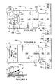
FIG. 1 is a plan view of a carrier blank for forming one carrier part, in accordance with an exemplary embodiment of the present invention. -
FIGs. 2 and 3 are plan views illustrating steps of an exemplary method of folding the carrier blank ofFIG. 1 . -
FIG. 4 is a partial side elevational view of a step of the method of folding the carrier blank ofFIG. 1 . -
FIG. 5 is a plan view of a step of the method of folding the carrier blank ofFIG. 1 . -
FIG. 6 is a partial side elevational view of a step of the method of folding the carrier blank ofFIG. 1 . -
FIG. 7 is a plan view of a collapsed carrier part formed from the carrier blank ofFIG. 1 . -
FIG. 8 is a perspective view of an erected carrier formed from a pair of the collapsed carrier parts ofFIG. 7 , showing bottles at least partially loaded in the carrier and operation of a top securing structure. -
FIG. 9 is a side elevational view of the carrier ofFIG. 8 , with the bottles completely loaded into the carrier. -
FIG. 10 is an end elevational view of the carrier ofFIG. 8 . -
FIG. 11 is a plan view of a carrier blank for forming one carrier part, in accordance with a second exemplary embodiment of the present invention. -
FIGs. 12-13 are plan views illustrating steps of an exemplary method of folding the carrier blank ofFIG. 11 . -
FIG. 14 is a plan view of a collapsed carrier part formed from the carrier blank ofFIG. 11 . -
FIG. 15 is a side elevational view of a carrier formed from two of the carrier part ofFIG. 14 . -
FIG. 16 is an end elevational view of the carrier ofFIG. 15 . -
FIG. 17 is a perspective view of the carrier ofFIG. 15 . -
FIG. 18 is a perspective view of an erected carrier part formed from the collapsed carrier part ofFIG. 14 . -
FIG. 19 is a perspective view of the carrier ofFIG. 15 showing operation of the top securing structure as a handle is engaged to lift the carrier. -
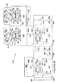
FIG. 20 is a blank for forming a basket style carrier according to a third embodiment of the invention. -
FIG. 21 is a plan view of the other-side of the blank ofFIG. 20 showing where adhesive may be applied in accordance with a first optional step in the construction of the basket carrier. -
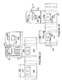
FIG. 22 is a plan view of a part-formed blank, wherein folding and adhesion of the central handle panels of the blank ofFIG. 21 is shown. -
FIG. 23 is a plan view of the blank ofFIG. 22 wherein further folding steps are illustrated. -
FIG. 24 is a plan view of the blank ofFIG. 23 wherein the application of glue and yet further folding steps are shown. -
FIG. 25 is a plan view of a basket carrier in flat-form. -
FIG. 26 is a perspective view from above and from the side of a basket carrier formed by opening the flat-form carrier ofFIG. 25 . -
FIG. 27 is a perspective view from above and from the side of a basket carrier formed by opening the flat-form carrier ofFIG. 25 . -
FIG. 28 is a perspective view from above of the carrier ofFIG. 27 having bottles disposed upon their tops in compartments formed from a retention structure, wherein the tops and necks of the bottles are supported by a supplementary retention feature. -
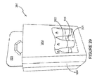
FIG. 29 is a side view of the basket carrier ofFIG. 27 fully loaded with articles and showing the neck portions of the bottom-up bottles being retained by the supplementary retention feature. - As required, detailed embodiments of the present invention are disclosed herein. It must be understood that the disclosed embodiments are merely exemplary of the invention that may be embodied in various and alternative forms, and combinations thereof. As used herein, the word "exemplary" is used expansively to refer to embodiments that serve as illustrations, specimens, models, or patterns. The figures are not necessarily to scale and some features may be exaggerated or minimized to show details of particular components. In other instances, well-known components, systems, materials, or methods have not been described in detail in order to avoid obscuring the present invention. Therefore, specific structural and functional details disclosed herein are not to be interpreted as limiting, but merely as a basis for the claims and as a representative basis for teaching one skilled in the art to variously employ the present invention.
- Referring now to the drawings, the drawings illustrate certain of the various aspects of exemplary embodiments of a carrier. Like numerals have, where possible, been used to denote similar features in the embodiments of
Figures 1 - 19 ; the reference numerals used inFigures 20 - 29 do not necessarily correlate to the numerals used inFigures 1- 19 ). - In the embodiments detailed herein, the term carrier refers, for the non-limiting purpose of illustrating the various features of the invention, to a container for engaging, carrying, and dispensing articles, such as clear plastic bottles. However, it is contemplated that the teachings of the invention can be applied to various containers, which may or may not be tapered and/or cylindrical. Other exemplary articles include metallic or glass bottles, aluminum cans, bowling pins, candles, and the like.
- As used herein, the term "neck" refers to a portion of a container adjacent an opening through which the container can dispense its contents. Typically, the opening is capped. The neck of a container may be, but is not necessarily, tapered with respect to a body of the article. As used herein, the term "heel" or base refers to the portion of a beverage container (e.g., a bottle) that is opposite the opening. Typically, the article rests on its base. In certain embodiments, the body (the primary content containing portion of the container) is tapered or curves at its base (the support surface of the container).
- Referring to the exemplary embodiment illustrated in
FIGs. 1-10 , acarrier 190 is formed from a pair ofblanks 100. Referring toFIG. 1 , the inside surface of the blank 100 is shown and the opposite side (not shown) of the blank 100 is its outside surface. The outside surface is used as its art side, which may bear printed product information, decorative designs, and brand specific indicia, such as logos, trademarks and associated copy. Either or both the inside and outside surface may be laminated or otherwise treated to make the carrier water-resistant, more durable, or to insulate the contents of the carrier. One advantage of thecarrier 190 described in further detail below is that substantially all of the exposed surfaces of thecarrier 190 are formed from the outside surface of theblanks 100. Thus, substantially all of the exposed surfaces of thecarrier 190 can be used to display printed matter, and the often less attractive inside surface opposite the art side is at least largely obscured. This is useful when used with transparent plastic or glass bottles having substantially clear contents (such as water) since the bottles and their contents do not substantially obstruct the exposed inside surfaces of the carrier. - The blank 100 is formed from a sheet of suitable substrate. It is to be understood that, as used herein, the term "suitable substrate" includes all manner of foldable sheet material such as paperboard, corrugated board, cardboard, plastic, combinations thereof, and the like. In the illustrated embodiments, a pair of the
unitary blanks 100 is used to form thecarrier 190. However, it should be recognized that one or other numbers of blanks may be employed, for example, to provide the carrier structure described in more detail below. - In the exemplary embodiment, the blank 100 is configured to form part of a carrier for packaging an exemplary arrangement of
exemplary articles 182. For example, the arrangement is a matrix including rows and columns such as a 2x3 arrangement ofarticles 182. The blank can be alternatively configured to form a carrier for packaging other articles and/or different arrangements of articles. - Referring again to
FIG. 1 , the blank 100 includes a series of panels that at least partially define ahandle 192, top andbase securing structures carrier 190. The panels are aligned along a longitudinal axis of the blank 100 and are hingedly connected one to the next along fold lines that extend transversely with respect to the longitudinal axis. - As used herein, the term "fold line" refers to all manner of lines that define hinge features of the blank, facilitate folding portions of the blank with respect to one another, or otherwise indicate optimal panel folding locations for the blank. A fold line is typically a scored line, an embossed line, or a debossed line.
- As used herein, the term "severance line" refers to all manner of lines that facilitate separating portions of the substrate from one another or that indicate optimal separation locations. Severance lines may be frangible or otherwise weakened lines, tear lines, cut lines, or slits.
- It should be understood that severance lines and fold lines can each include elements that are formed in the substrate of the blank including perforations, a line of perforations, a line of short slits, a line of half-cuts, a single half-cut, a cut line, an interrupted cut line, slits, scores, any combination thereof, and the like. The elements can be dimensioned and arranged to provide the desired functionality. For example, a line of perforations can be dimensioned or designed with degrees of weakness to define a fold line and/or a severance line. The line of perforations can be designed to facilitate folding and resist breaking, to facilitate folding and facilitate breaking with more effort, or to facilitate breaking with little effort.
- The panels include: an
inner handle panel 102; anouter handle panel 106; atop panel 116; acap panel 120; ayoke panel 130; acentral panel 134; arear base panel 138; afront base panel 142; aninner heel panel 146; and anouter heel panel 150. Theinner handle panel 102 is hingedly connected to theouter handle panel 106 along afold line 104. Theouter handle panel 106 is hingedly connected to thetop panel 116 alongfold line 112, and thetop panel 116 is hingedly connected to thecap panel 120 along afold line 118. Thecap panel 120 is hingedly connected to theyoke panel 130 along afold line 122 and theyoke panel 130 is hingedly connected to thecentral panel 134 alongfold line 132. Thecentral panel 134 is hingedly connected to therear base panel 138 alongfold line 136 and therear base panel 138 is hingedly connected to thefront base panel 142 alongfold line 140. Thefront base panel 142 is hingedly connected to theinner heel panel 146 alongfold line 144, and theinner heel panel 146 is hingedly connected to theouter heel panel 150 along thefold line 148. It should be noted that thefold line 140 is primarily used in collapsing the blank 100 prior to fully erecting thecarrier 190, as will be described in more detail below. Ahandle flap 110 is hingedly connected toouter handle panel 106 alongfold line 108. -
Side heel panels outer heel panel 150 along thefold lines heel panel tab 158 that is hingedly connected to theside heel panel 154 along afold line 156 and aheel panel tab 166 that is hingedly connected to theside heel panel 162 along afold line 164. In addition, thehandle cushion panel 110 is hingedly connected to theouter handle panel 106 along afold line 108. - The illustrated
yoke panel 130 includesneck retaining structures resistance tabs neck retaining structures resistance tabs - Assembling a
carrier part 180 from the blank 100 may be accomplished with the folding and securing operations as described herein. The operations can be performed by automatic erecting machinery and/or manually. The method of performing the assembling process is not limited to the exemplary method described herein. Particularly, the order of the steps can be altered according to manufacturing requirements, steps may be added or omitted, and the means for securing components to one another may vary. The surfaces of sheet material may be secured together by suitable means for securing including tape, staples, interlocking folds, VELCRO®, glue or other adhesives, combinations thereof, and the like. - Referring to
FIGs. 1-7 , the blank 100 is assembled to form acollapsed carrier part 180. Referring toFIGs. 1 and2 , with the artwork side facing downward, the blank 100 is folded inwardly along thefold line 118, such that at least theinner handle panel 102 overlaps thecentral panel 134. Referring toFIGs. 2-4 , theouter handle panel 106 is folded outwardly along thefold lines inner handle panel 102 is folded along thefold line 104 to overlay theouter handle panel 106. Theinner handle panel 102 and thecentral panel 134 are secured to one another. - Referring to
FIGs. 3 ,5 and 6 , the blank 100 is folded inwardly alongfold lines front base panel 142,inner heel panel 146, andouter heel panel 150 are collapsed beneath thecentral panel 134 and therear base panel 138. Referring toFIGs. 5 and 7 , theside heel panels fold lines rear heel panels central panel 134. Therear heel panels central panel 134 are secured together to define an encircling strip comprising theouter heel panel 150 andside heel panels FIG. 7 , thecarrier part 180 is formed in a collapsed condition. The non-artwork surface ofcentral panels 134 of two of thecollapsed carrier parts 180 are secured together (seeFIG. 10 ) to form acarrier 190 in a collapsed condition. - The illustrated
carriers 190 are adapted to hold a group of similarly dimensioned articles, such as theclear plastic bottles 182, in a matrix arrangement of rows. Here, eachcarrier part 180 holds a row of threebottles 182 such that thecarrier 190 holds two rows of threebottles 182. Eachbottle 182 is substantially cylindrical with a cappedtop end 184 and abase end 186. Thebottle 182 includes atapered neck 188 and cap at thetop end 184. - Referring to
FIGs. 8-10 , thecarrier 190 can be erected from the collapsed condition. Generally, thefront handle panels handle 192; thetop panel 116, thecap panel 120, and theyoke panel 130 provided atop securing structure 192; therear base panel 138, thefront base panel 142, theouter heel panel 150, and theside heel panels base securing structure 196; and thecentral panels 134 provide opposing surfaces of acentral wall 198. In this embodiment, thehandle 192 is adjacent thetop securing structure 194 with thebottles 182 carried right side up (in other words, in a normal configuration). - Referring to
FIG. 8 , thecarrier 190 can be partially erected and then loaded withbottles 182 prior to fully erecting thecarrier 190 to hold thebottles 182 in place. More specifically, thecarrier 190 is partially erected as follows. Two collapsedcarrier parts 180 are secured to one another by adhering the inside (non-art) surface of each respectivecentral panel 134 in a face contacting arrangement to form the compositecentral wall 198. The twocentral panels 134, one from eachcollapsed carrier part 180, can be secured to one another using any suitable means, including but not limited to, glue or other adhesives, tape, staples or other connectors, and the like. - Prior to or after securing the two
carrier parts 180 together, thebase securing structures 196 are erected to partially erect thecarrier 190. Theouter heel panel 150 and theside heel panels fold lines rear base panel 138 and thefront base panel 142 are folded away from one another alongfold line 140 until they are substantially coplanar. As such, each of thebase securing structures 196 are erected as a trough that is configured to receive the base ends 186 ofbottles 182. Thebottles 182 are loaded into thebase securing structures 196 such that the base ends 186 are supported from below by therear base panel 138 and thefront base panel 142 and are laterally supported by theouter heel panel 150, theside heel panels central panel 134. - Referring to
FIGs. 8 and 10 , thecarrier 190 is fully erected when thetop securing structure 194 is then lowered over the top ends 184 of thebottles 182. Thetop securing structure 194 is folded alongfold lines inner handle panel 102, thetop panel 116, thecap panel 120, and theyoke panel 130 form a tubular structure and the top ends 184 are received in the tubular structure through theneck retaining structures resistance tabs neck 188 of thebottles 182 under the cap 184 (top end). Theresistance tabs caps 184 through theneck retaining structures top securing structure 194 over the top ends 184 of thebottles 182. - The
resistance tabs neck retaining structures fold line 132 or otherwise thecentral wall 198. In the illustrated embodiment, theresistance tabs neck receiving apertures bottles 182. The direction of movement of eachbottle 182 is limited by the structure of thecarrier 190 and theadjacent bottles 182. For example, lateral movement of themiddle bottle 182 in each row is restricted by both theouter bottles 182 and thecentral wall 198. Theneck retaining structure 126 allows some movement due to tolerances so themiddle bottle 182 can have some movement normal to thecentral wall 198. Theresistance tabs 127 are positioned opposite thecentral wall 198 to resist this movement and thus force themiddle bottle 182 against thecentral wall 198. Similarly, theresistance tabs 125, 129 force theouter bottles 182 against themiddle bottle 182 and thecentral wall 198. In general, theresistance tabs bottles 182 inwardly and resist movement away from thecarrier 190. - When the
handle 192 is engaged, the twocarrier parts 180 of thecarrier 190 are configured such that the forces applied by the weight of thebottles 182 in onecarrier part 180 counter-balance forces applied by the weight of thebottles 182 in the other carrier part. By engaging thehandle 192, thecarrier parts 180 are forced together, particularly at the lower end, by the weight of thebottles 182. As such, eachcarrier part 180 is configured to provide structural support to theother carrier part 180. - The
carrier 190 is tamper evident and tamper resistant, in part because to remove abottle 182, a user must dislodge the cap from aneck receiving aperture top securing structure 194 or tearing thebase securing structure 196. Thus, unlike the typical 6-pack carrier, unwitting or intentional removal of a single item without detection is discouraged. - Referring to
FIGs. 11-18 , a second exemplary embodiment of the invention is described. A blank 200 of the second exemplary embodiment has features that are substantially the same as the blank 100 of the first exemplary embodiment. However, the first embodiment is configured for upright article packaging (also referred to as 'normal orientation'), whereas the second exemplary embodiment is configured for upside down (also referred to as 'inverted orientation') article packaging. - The description of elements of the first exemplary embodiment that are substantially similar to elements of the second exemplary embodiment may not be repeated for the elements of the second exemplary embodiment. Rather, the description of the second exemplary embodiment will be directed to the alternative features of the second exemplary embodiment.
- Referring to
FIG. 11 , the blank 200 includes: ahandle panel 202; an outercentral panel 210; ayoke panel 220; acap panel 224; abottom panel 228; an innercentral panel 232; a reartop panel 258; ahandle panel 259; a fronttop panel 260; and anouter heel panel 272. Thehandle panel 202 is hingedly connected to the outercentral panel 210 alongfold lines central panel 210 is hingedly connected to theyoke panel 220 along afold line 212 and theyoke panel 220 is hingedly connected to thecap panel 224 along afold line 222. Thecap panel 224 is hingedly connected to thebottom panel 228 along afold line 226 and thebottom panel 228 is hingedly connected to the innercentral panel 232 along afold line 230. The innercentral panel 232 is hingedly connected to the top reartop panel 258 alongfold line 250 and the reartop panel 258 is hingedly connected to the fronttop panel 260 along fold line 262.The fronttop panel 260 is hingedly connected to theouter heel panel 272 alongfold line 270. Together, the fronttop panel 260 and reartop panel 258 define atop wall 268. The illustratedyoke panel 220 includesneck retaining structures resistance tabs - A
handle panel 259 is hingedly connected to the innercentral panel 232 alongfold line 250. Thehandle panel 259 is defined in part in the fronttop panel 260 and in part in the reartop panel 258 along aseverance line 264. When handle 259 is separated from the fronttop panel 260 and the reartop panel 258, referring momentarily toFIGs. 16 and17 , anaperture 293 is revealed in thebottom support structure 296 adjacent thehandle 292. Continuing withFIG. 11 , ahandle panel 206 is hingedly connected to thehandle panel 202 along afold line 204. - The
side heel panels central panel 232 along thefold lines heel panel tab 240 is hingedly connected to theside heel panel 236 along afold line 238 and aheel panel tab 248 is hingedly connected to theside heel panel 244 along afold line 246. - Referring to
FIGs. 11-18 , the blank 200 is assembled to form acarrier part 280 in a collapsed condition according to an exemplary method. Referring toFIGs. 11 and12 , with the artwork side facing downward, the blank 200 is folded inwardly along thefold line 226 such that outercentral panel 210 overlaps the innercentral panel 232. The outercentral panel 210 and the innercentral panel 232 are secured together. Referring toFIGs. 12 and 13 , the fronttop panel 260 is folded inwardly along thefold line 262 to overlap thehandle panel 202 and reartop panel 258; theheel panel 272 overlaps the outercentral panel 210. Referring toFIGs. 13 and14 , theheel panel tabs fold lines outer heel panel 272 to define an encircling strip comprising theouter heel panel 272 andside heel panels FIG. 14 , thecarrier part 280 is formed in a collapsed condition, which can be erected as shown inFIG. 18 . It should be noted that thefold lines carrier part 280 prior to fully erecting thecarrier 290. - A pair of
collapsed carrier parts 280 is secured to one another to formcarrier 290 in collapsed condition. As above, substantially every exposed outer surface of thecarrier 290 is the outer surface or artwork side of the blank 200 and thus the surface area that is available for purposes of displaying information is maximized, particularly when clearplastic bottles 182 with clear contents are loaded in thecarrier 290 since they do not obstruct the display on the outercentral panel 210. - Referring to
FIGs. 15-17 , similar to above, thecarrier 290 includes ahandle 292, atop securing structure 294, abase securing structure 296, and acentral wall 298. In this embodiment, thehandle 292 is adjacent thebase securing structure 296 with thebottles 182 carried upside down. Theaperture 293 is defined in thetop wall 268 of thebase securing structure 196 and is configured to allow light though thebase structure 296 to illuminate thebottles 182. - As above, the
carrier 290 is partially erected, loaded, and then fully erected to secure articles such asbottles 182. Thearticles 182 are loaded upside down with the bases received in thebase securing structure 296. Thetop securing structure 294 is then folded upwardly such that thecaps 184 are received in theneck receiving apertures resistance tabs - Referring to
FIG. 19 , when thehandle 292 is engaged to lift thecarrier 290, the top securingstructures 294 flex downward and inward. As above, thecarrier parts 280 support one another as the weight of thebottles 182 forces the carrier parts against one another. For example, thecarrier parts 280 work together to maintain the position of thecentral wall 298, which keeps the top securingstructures 294 from over-rotating. Theresistance tabs neck receiving apertures - Referring to
FIG. 20 there is shown a blank 310 for forming a basket style carrier 397 (which is shown inFIGs. 26 to 29 ) according to a third illustrated optional and exemplary embodiment of the invention. The reference numerals used to denote features of the third embodiment do not necessarily accord to the reference numerals used inFigures 1-19 illustrating the first and second embodiments. - The blank 310 is formed from a unitary piece of foldable sheet material such as paperboard. The blank 310 comprises: a
first handle panel 324 foldably connected along aside connection 344 to asecond handle panel 322. Optionally theside connection 344 extends for between about 40% and about 60% of the height of thehandle panels basket carrier 397 from the blank 310. Eachhandle panel handle aperture 390 with an arrangement of cushioning flaps 392, 394, 396 hinged thereto alongfold line 388 formed in anupper portion handle panels second handle panels 324/325 and 322/323 may also be referred to as central panels as they are disposed, albeit optionally, substantially centrally of thebasket carrier 397 once formed. Using twocentral handle panels handle aperture 390 andcushioning flaps handle panels - Returning to the blank 310, the blank 310 comprises: a first
bottom panel 316 hinged directly to thefirst handle panel 324 alongfold line 346a; afirst side panel 312 foldably connected to the firstbottom panel 316 alongfold line 346b; asecond side panel 314; and a secondbottom panel 318 foldably connected to thesecond side panel 314 along afold line 348b and connected to aglue panel 320 along afurther fold line 348a. - A series of end
wall forming panels first side panel 312 and are hinged thereto alongfold lines wall forming panels second side panels FIG 1 . Thesepanels -
Optional fold lines wall forming panels lines wall glue panel 342 is provided to adhereend wall panel 340 to endwall panel 326. -
Optional apertures basket carrier 397. During construction, the material either side ofapertures panels fold lines bottom panels handle panels apertures fold - Referring now to the
retention structures 384/378/386/382 that are struck from thehandle panels retention structure 384/378/386/382 comprises a pair ofpartition tabs 384/378, 386/382. Eachpartition tab 384/378, 386/382 is optionally split into two integral and contiguous parts, afirst part second part partition tab 384/378, 386/382 has a shape approximately similar to a wine glass. The shape of thepartition tabs 384/378, 386/382 is optional, but arises at least to some extent because of the provision ofcorner joints fold lines partition tab 384/378, 386/382 once folded, approximately 90°, out of the plane of the first andsecond handle panels 324, 322 (seeFIG. 8 ), to rotate or hinge, approximately another 90°, out of the plane of the corner joints 371, 373, 375, 377 so that eachpartition tab 384/378, 386/382 defines a cell and forms a barrier between two adjacent articles (seeFIG. 11 ). - Each corner joint 371, 373, 375, 377 is defined by two
fold lines 370/374; 372/374; 372/376; 370/376 that are linked by a radiused or arcuate line ofseparation 379. The arcuate lines ofseparation 379 define the bowl-shaped portions orsecond parts partition tabs 384/378, 386/382. What becomes, in a set up basket, a lower edge of each of thepartition tabs 384/378; 386/382 is defined by a common line of separation 381 that separates each pair ofpartition tabs 384/378, 386/382 of eachretention structure 384/378/386/382. - The
first parts partition tabs 384/378, 386/382 of eachretention structure 384/378/386/382 are connected to thehandle panels first parts fold lines corner joints respective handle panel fold lines fold line handle panels bottom panels fold lines bottom panels side panels joint fold lines bottom panels basket carrier 397 is erected. Thefirst parts partition tabs 384/378, 386/382 are integrally formed with and are contiguous with thesecond parts partition tabs 384/378, 386/382 of each retention structure are further hingedly connected to aglue flap 380 by virtue of the corner joints 377, 375. More specifically, theglue flap 380 is hinged to the corner joints 377, 375 alongfold lines partition tabs 384/378, 386/382 are hinged to the same corner joints 377, 375 respectively by means offold lines carrier 397, the glue flaps 380 connect the retention structures to the internal faces of theside panels single glue flap 380 is required for twopartition tabs 384/378, 386/382 thus making construction easier compared to prior art carriers where each partition tab requires its own glue flap. - The
glue panel 320 is provided to affix the secondbottom panel 318 to thefirst handle panel 324. - The end
wall forming panels second side panels panel glue flap 342 of the blank 310 are sufficiently sized so that thebasket carrier 397 formed from the blank 310 can accommodate a supplementary retention structure for supporting and retaining the tops and necks of bottles 'A'. Each of the first andsecond side panels retention panel second side panel fold line retention panel second side panel fold lines panel fold lines bottom panels basket carrier 397 is erected. A retentionpanel glue flap retention panel first handle panels FIGs. 26 and29 for an illustration of the supplementary retention structure formed from theretention panel 321 struck from the first side wall 312). - Optionally, an
article support retention panels basket carrier 397. In the illustrated example acircular aperture 341, 333 is provided by eachretention panel semicircular notch retention panel - Turning to the construction of a basket carrier 397 (illustrated in FlGs. 26 - 29), it is envisaged that the
carrier 397 can be formed by a series of sequential folding operations, optionally in a straight line machine so that the carrier is not required to be rotated or inverted to complete its construction. The folding process is not limited to that described below and may be altered according to particular manufacturing requirements. - Referring now to FlGs. 21 to 25 a sequence of folding and gluing operations is illustrated. The first and
second handle panels second handle panel 322 is affixed to the firstbottom panel 316, (optionally by means of adhesive applied in regions G1', G2' and G3' and folding in the direction of arrow F1). Subsequently, affixing means may be applied to the retention panel glue flaps 319, 315 in optional regions G4'. Adhesive in the region of G5' is also applied for affixing theglue flap 380 to thefirst side panel 312. InFIG. 22 , it is shown how the second andfirst handle panels FIG. 23 ), into overlapping relationship with thefirst side panel 312. In this way, the retentionpanel glue flap 319 and theglue flap 380 of theretention structure 384/378/386/382 are affixed to thesecond handle panel 322. Additionally, the secondbottom panel 318 andglue panel 320 are together folded aboutfold line 348b so that theglue panel 320 is affixed to the retentionpanel glue flap 315 as indicated by arrow F2' illustrated inFIG. 23 . - The subsequent construction of the
basket carrier 397 is illustrated inFIG. 16 .Glue panel 320 is then affixed (by using adhesive applied in optional regions G6') to thefirst handle panel 324. In this way, theretention panel 317 is indirectly affixed to thefirst handle panel 324. - Adhesive, optionally a hot melt glue, may be applied in optional glue regions G8', G6', G7', on the
second side panel 314;glue panel 320; and endwall glue panel 342 respectively (as is illustrated inFIG. 24 ). The part-formed blank is then folded about fold line 360 (as indicated by arrow F5' inFIG. 25 ) until the firstbottom panel 316 overlays the secondbottom panel 318; theglue flap 380 is affixed to thesecond side panel 314; theglue panel 320 is affixed to thefirst handle panel 324; and the endwall glue panel 342 is affixed to theend wall panel 326. The resulting structure, as shown inFIG. 25 , is a flat-folded basket carrier. - The
basket carrier 397 opened out from the flat-form structure ofFIG. 25 is illustrated in perspective view inFIG. 26 . The configuration, structure and operation of theretention structure 384/378/386/382 is now described further. Theopen basket carrier 397 comprises aretention structure 384/378/386/382 that extends from each of the second andfirst handle panels second side panel retention structure 384/378/386/382 is below the top edge of each of the first andsecond side panels constituent partition tabs 384/378, 386/382 away from one another by rotating eachpartition tab 384/378, 386/382 aboutfold line partition tabs 384/378, 386/382 are separated by a cut line; in other embodiments, thepartition tabs 384/378, 386/382 may be frangibly connected by a perforation line or connecting nick portions. Optionally, though preferably, top-loading of a bottle A, leading with the bottle top and neck, into a central cell (relative to theside walls 312, 314) can automatically cause the separation of thepartition tabs 384/378, 386/382 and cause the pivotal rotation of thepartition tabs 384/378, 386/382 aboutfold line FIG. 28 , bottles 'A' have been top-loaded (leading with the bottle top) into cells between thepartition tabs 386/382. In its constructed and in-use position thepartition tab 386/382 has been rotated substantially 90° relative to the plane of thesecond handle panel 322 and has been further rotated substantially 90° relative to the plane of the corner joints 371, 373, 375, 377. - The pivotal movement of the
partition tab 386/382 can be described with reference to Cartesian axes of the set-upbasket carrier 397 depicted inFIG. 26 . An axis between the top edge and bottom edge (346b) of thefirst handle panel 324 is an x-axis; an axis along the width of thatfirst handle panel 324, as defined byfold line 346a, is a y-axis; and an orthogonal axis between the uprightfirst handle panel 324 and the first side panel 314 (in a set-up basket carrier 397 - seeFIG. 26 ) is a z-axis. Theretention structure 384/378/386/382 is, at least in part, moved from the x-y plane into the y-z plane and then into the x-z plane. This is achieved because the partition tabs of theretention structure 384/378/386/382 are rotated aboutfold lines 370/372 and 374/376 that are disposed at 90° relative to one another. The substantially horizontally disposedcorner joints - The formation of
retention structures 384/378/386/382 directly from the first andsecond handle panels carrier 397 to the top of thecarrier 397 may provide strength, structural integrity and robustness to thebasket carrier 397. Further, the provision ofpartition tabs 384/378, 386/382 that rotate from a y-z plane into an x-z may assist with bottle alignment as there is a clear target to direct the central inverted-bottle toward. - Alternative or
additional retention panels first handle panels retention panels bottom panels 318/316 into which the necks and/or top portions of the bottles 'A' can be positioned and thereby supported. InFIG. 28 six bottles 'A' are shown in an upside down (inverted) configuration with the base of the bottles 'A' disposed uppermost and the necks of the bottles supported in bottle supports 343, 341, 345. Bottles oriented in this manner may allow for example, sediment (for example fleshy parts of a juice), flavouring or a first-part of a two-part beverage to settle in the neck of the bottle. Then, prior to opening of the bottle 'A', when the bottle is replaced into a normal upright position with the neck uppermost, the sediment, flavouring or first-part of a two-part beverage will flow through other liquid within the bottle to mix or distribute the sediment, flavouring or first-part of a two-part beverage. - It can be appreciated that various changes may be made within the scope of the present invention, for example, the size and shape of the panels and apertures may be adjusted to accommodate articles of differing size or shape. In other embodiments of the invention it is envisaged that in a 2 x 2 basket carrier, the first retention structure may be omitted or may comprise only one
partition tab 384/378, 386/382. In further embodiments only one supplementary retention structure may be provided. It is also envisaged that basket carriers utilizing the retention structure of the present invention may be shaped, sized and configured to accommodate more or fewer than six articles. Further, thesupplementary retention structure partition tabs 384/378, 386/382, may take many and various shapes and are not limited to the "wine-glass-shaped"partition tabs 384/378, 386/382 shown. - It is also envisaged that where provided the article supports 341, 343, 345, 333, 335, 337 may all be similarly shaped, or differently sized. Furthermore, one or more of the article supports 341, 343, 345, 333, 335, 337 may be sized to support a base portion of an article and the basket carrier may comprise a combination of upright and inverted articles. Alternatively, the retention panels in other embodiments, may be sized sufficiently such that each
article support - It will be recognised that as used herein, directional references such as "top", "bottom", "front", "back", "end", "side", "inner", "outer", "upper" and "lower" do not limit the respective panels to such orientation, but merely serve to distinguish these panels from one another. Any reference to hinged connection should not be construed as necessarily referring to a single fold line only; indeed it is envisaged that hinged connection can be formed from one or more of the following, a short slit, a frangible line or a fold line without departing from the scope of the invention.
- The present invention has been illustrated in relation to particular embodiments that are intended in all respects to be illustrative rather than restrictive. Those skilled in the art will recognize that the present invention is capable of many modifications and variations without departing from the scope of the invention. For example, as used herein, directional references such as top, base, bottom, end, side, inner, outer, upper, middle, lower, front, and rear do not limit the respective walls of the carrier to such orientation, but merely serve to distinguish these walls from one another. Any reference to hinged connection should not be construed as necessarily referring to a junction including a single hinge only; indeed, it is envisaged that hinged connection can be formed from one or more potentially disparate means for hingedly connecting materials.
- The above-described embodiments are merely exemplary illustrations of implementations set forth for a clear understanding of the principles of the invention. Variations, modifications, and combinations may be made to the above-described embodiments without departing from the scope of the claims. All such variations, modifications, and combinations are included herein by the scope of this disclosure and the following claims.
Claims (13)
1. A carrier for securing a plurality of articles having a base and a top, comprising:
a composite central wall formed from at least two central panels;
a composite handle extending from the central wall, the composite handle being formed from at least two handle panels, wherein at least one of the handle panels is contiguous to one of the central panels;
a pair of cantilevered top securing structures that extend substantially perpendicularly from opposite sides of an upper end of the composite central wall, each top securing structure comprising a yoke panel for retaining the top of at least one article; and
a pair of base securing structures, each comprising an encircling strip that is connected at opposed ends thereof to opposed sides of the composite central wall, the encircling strip being configured to retain the base of at least one article.
2. The carrier of claim 1, formed from a pair of substantially identical carrier parts secured together.
3. The carrier of claim 2, wherein substantially all of the outward facing surfaces of each of the carrier part are formed from the surface of one side of a respective unitary blank that forms the each carrier part.
4. The carrier of claim 1, wherein the handle is adjacent the pair of top securing structures.
5. The carrier of claim 1, wherein the handle is adjacent the pair of base securing structures.
6. The carrier of claim 5, wherein the base securing structure includes an aperture adjacent the handle.
5. The carrier of claim 1, wherein at least one of the top securing structures comprises a tubular structure comprising the yoke panel in which at least one neck receiving aperture is defined.
6. The carrier of claim 5, wherein the at least one neck receiving aperture comprises resistive tabs.
7. The carrier of claim 6, wherein the resistive tabs are disposed along only part of a periphery of the at least one neck receiving aperture.
8. The carrier of claim 7, wherein the part of the periphery of the at least one neck receiving aperture is opposite the central wall.
9. The carrier of claim 7, wherein the at least one neck receiving aperture comprises a first neck receiving aperture and a second neck receiving aperture, wherein the part of the periphery of the first neck receiving aperture is oriented in a different direction than that of the part of the periphery of the second neck receiving aperture.
10. The carrier of claim 7, wherein the resistive tabs are configured to resist the movement of an article in a direction that is not obstructed by the central wall or other articles.
11. A carrier for securing one or more articles having a base and a top, the carrier comprising:
a composite central wall formed from at least two central panels;
a composite handle being formed from the at least two handle panels;
at least one article top securing structure; and
at least one article base securing structure, wherein the at least one article top securing structure is disposed at an elevation within the carrier that is below the elevation of at least one base securing structure such that the carrier is configured to support one or more articles in an inverted position, wherein the base of the article is uppermost and the top of the article is lowermost.
Applications Claiming Priority (2)
| Application Number | Priority Date | Filing Date | Title |
|---|---|---|---|
| US201161472570P | 2011-04-06 | 2011-04-06 | |
| GBGB1205068.8A GB201205068D0 (en) | 2012-03-22 | 2012-03-22 | Basket carrier and blank therefor |
Publications (1)
| Publication Number | Publication Date |
|---|---|
| EP2508444A1 true EP2508444A1 (en) | 2012-10-10 |
Family
ID=46086950
Family Applications (1)
| Application Number | Title | Priority Date | Filing Date |
|---|---|---|---|
| EP12163332A Withdrawn EP2508444A1 (en) | 2011-04-06 | 2012-04-05 | Carrier for articles |
Country Status (4)
| Country | Link |
|---|---|
| EP (1) | EP2508444A1 (en) |
| AU (2) | AU2012202005B2 (en) |
| GB (1) | GB201205068D0 (en) |
| WO (1) | WO2013142748A1 (en) |
Cited By (1)
| Publication number | Priority date | Publication date | Assignee | Title |
|---|---|---|---|---|
| WO2013142748A1 (en) * | 2012-03-22 | 2013-09-26 | Meadwestvaco Packaging Systems, Llc | Basket carrier and blank therefor |
Citations (5)
| Publication number | Priority date | Publication date | Assignee | Title |
|---|---|---|---|---|
| US1949207A (en) * | 1932-06-24 | 1934-02-27 | Kinkead | Bottle carrier |
| GB938753A (en) * | 1961-06-17 | 1963-10-09 | Pazo Company Ltd | Carriers for bottles or like containers |
| CH503621A (en) * | 1970-03-02 | 1971-02-28 | E H Schelling Ag | Bottle carrier |
| FR2239877A5 (en) * | 1973-07-31 | 1975-02-28 | Sauterot Drac | Display packaging with carrying handle for bottles - has open front and top section which passes over bottle necks |
| US5439110A (en) * | 1994-06-16 | 1995-08-08 | Riverwood International Corporation | Two-tiered article package |
Family Cites Families (3)
| Publication number | Priority date | Publication date | Assignee | Title |
|---|---|---|---|---|
| GB0819187D0 (en) * | 2008-10-20 | 2008-11-26 | Meadwestvaco Packaging Systems | Carton for packaging articles and method therefor |
| KR102067950B1 (en) * | 2010-04-22 | 2020-01-17 | 웨스트락 패키징 시스템스, 엘엘씨 | Carton |
| GB201205068D0 (en) * | 2012-03-22 | 2012-05-09 | Meadwestvaco Packaging Systems | Basket carrier and blank therefor |
-
2012
- 2012-03-22 GB GBGB1205068.8A patent/GB201205068D0/en not_active Ceased
- 2012-04-05 AU AU2012202005A patent/AU2012202005B2/en not_active Expired - Fee Related
- 2012-04-05 EP EP12163332A patent/EP2508444A1/en not_active Withdrawn
-
2013
- 2013-03-22 AU AU2013204561A patent/AU2013204561A1/en not_active Abandoned
- 2013-03-22 WO PCT/US2013/033402 patent/WO2013142748A1/en not_active Ceased
Patent Citations (5)
| Publication number | Priority date | Publication date | Assignee | Title |
|---|---|---|---|---|
| US1949207A (en) * | 1932-06-24 | 1934-02-27 | Kinkead | Bottle carrier |
| GB938753A (en) * | 1961-06-17 | 1963-10-09 | Pazo Company Ltd | Carriers for bottles or like containers |
| CH503621A (en) * | 1970-03-02 | 1971-02-28 | E H Schelling Ag | Bottle carrier |
| FR2239877A5 (en) * | 1973-07-31 | 1975-02-28 | Sauterot Drac | Display packaging with carrying handle for bottles - has open front and top section which passes over bottle necks |
| US5439110A (en) * | 1994-06-16 | 1995-08-08 | Riverwood International Corporation | Two-tiered article package |
Cited By (1)
| Publication number | Priority date | Publication date | Assignee | Title |
|---|---|---|---|---|
| WO2013142748A1 (en) * | 2012-03-22 | 2013-09-26 | Meadwestvaco Packaging Systems, Llc | Basket carrier and blank therefor |
Also Published As
| Publication number | Publication date |
|---|---|
| GB201205068D0 (en) | 2012-05-09 |
| AU2012202005B2 (en) | 2014-02-20 |
| WO2013142748A1 (en) | 2013-09-26 |
| AU2012202005A1 (en) | 2012-10-25 |
| AU2013204561A1 (en) | 2013-10-10 |
Similar Documents
| Publication | Publication Date | Title |
|---|---|---|
| EP1737745B1 (en) | Carton for multiple articles | |
| EP1937571B1 (en) | Cartons with dispensing features | |
| US7677387B2 (en) | Carrier for containers | |
| EP1737736B1 (en) | Carton and carton blank with reinforced top | |
| EP3201095B1 (en) | Convertible carrier | |
| EP1737746B1 (en) | Carton and two-part carton blank | |
| KR20130136498A (en) | Package for containers | |
| WO2016018758A1 (en) | Carton and carton blank and a handle structure therefore | |
| WO2006108098A1 (en) | Top gripping article carrier having brace tab | |
| AU2012231228B2 (en) | Carton with handle | |
| US20240375839A1 (en) | Carton For Containers | |
| AU2012202005B2 (en) | Carrier for articles | |
| CN114585570A (en) | Article carriers and blanks therefor | |
| TWI874392B (en) | Article carrier and blank therfor | |
| US20140373486A1 (en) | Carton, carton blank and method of forming a loaded carton | |
| US20090008437A1 (en) | Carton and Carton Blank with Access | |
| WO2025245522A1 (en) | Article carrier and blank therefor | |
| AU2013206237A1 (en) | Packaging system, carton and blank |
Legal Events
| Date | Code | Title | Description |
|---|---|---|---|
| PUAI | Public reference made under article 153(3) epc to a published international application that has entered the european phase |
Free format text: ORIGINAL CODE: 0009012 |
|
| 17P | Request for examination filed |
Effective date: 20120405 |
|
| AK | Designated contracting states |
Kind code of ref document: A1 Designated state(s): AL AT BE BG CH CY CZ DE DK EE ES FI FR GB GR HR HU IE IS IT LI LT LU LV MC MK MT NL NO PL PT RO RS SE SI SK SM TR |
|
| AX | Request for extension of the european patent |
Extension state: BA ME |
|
| STAA | Information on the status of an ep patent application or granted ep patent |
Free format text: STATUS: THE APPLICATION IS DEEMED TO BE WITHDRAWN |
|
| 18D | Application deemed to be withdrawn |
Effective date: 20130411 |