EP2508297A1 - Machine tool balancer and balance control method - Google Patents
Machine tool balancer and balance control method Download PDFInfo
- Publication number
- EP2508297A1 EP2508297A1 EP10832964A EP10832964A EP2508297A1 EP 2508297 A1 EP2508297 A1 EP 2508297A1 EP 10832964 A EP10832964 A EP 10832964A EP 10832964 A EP10832964 A EP 10832964A EP 2508297 A1 EP2508297 A1 EP 2508297A1
- Authority
- EP
- European Patent Office
- Prior art keywords
- ram
- guide block
- guide
- saddle
- gravity
- Prior art date
- Legal status (The legal status is an assumption and is not a legal conclusion. Google has not performed a legal analysis and makes no representation as to the accuracy of the status listed.)
- Withdrawn
Links
Images





Classifications
-
- B—PERFORMING OPERATIONS; TRANSPORTING
- B23—MACHINE TOOLS; METAL-WORKING NOT OTHERWISE PROVIDED FOR
- B23Q—DETAILS, COMPONENTS, OR ACCESSORIES FOR MACHINE TOOLS, e.g. ARRANGEMENTS FOR COPYING OR CONTROLLING; MACHINE TOOLS IN GENERAL CHARACTERISED BY THE CONSTRUCTION OF PARTICULAR DETAILS OR COMPONENTS; COMBINATIONS OR ASSOCIATIONS OF METAL-WORKING MACHINES, NOT DIRECTED TO A PARTICULAR RESULT
- B23Q1/00—Members which are comprised in the general build-up of a form of machine, particularly relatively large fixed members
- B23Q1/72—Auxiliary arrangements; Interconnections between auxiliary tables and movable machine elements
-
- B—PERFORMING OPERATIONS; TRANSPORTING
- B23—MACHINE TOOLS; METAL-WORKING NOT OTHERWISE PROVIDED FOR
- B23Q—DETAILS, COMPONENTS, OR ACCESSORIES FOR MACHINE TOOLS, e.g. ARRANGEMENTS FOR COPYING OR CONTROLLING; MACHINE TOOLS IN GENERAL CHARACTERISED BY THE CONSTRUCTION OF PARTICULAR DETAILS OR COMPONENTS; COMBINATIONS OR ASSOCIATIONS OF METAL-WORKING MACHINES, NOT DIRECTED TO A PARTICULAR RESULT
- B23Q11/00—Accessories fitted to machine tools for keeping tools or parts of the machine in good working condition or for cooling work; Safety devices specially combined with or arranged in, or specially adapted for use in connection with, machine tools
- B23Q11/001—Arrangements compensating weight or flexion on parts of the machine
- B23Q11/0017—Arrangements compensating weight or flexion on parts of the machine compensating the weight of vertically moving elements, e.g. by balancing liftable machine parts
-
- B—PERFORMING OPERATIONS; TRANSPORTING
- B23—MACHINE TOOLS; METAL-WORKING NOT OTHERWISE PROVIDED FOR
- B23B—TURNING; BORING
- B23B47/00—Constructional features of components specially designed for boring or drilling machines; Accessories therefor
- B23B47/26—Liftable or lowerable drill heads or headstocks; Balancing arrangements therefor
Definitions
- the present invention relates to a balancer of a machine tool such as a horizontal boring machine and to a balance control method.
- Fig. 16 shows a conventional balancer of a machine tool.
- the machine tool shown in Fig. 16 is a ram-stock-type horizontal boring machine 50.
- a ram stock 51 is supported at two spots as Bessel points thereof by an arm 53, and the arm 53 is suspended at the center of gravity thereof by a chain 55.
- the chain 55 is coupled to the center of gravity of a counterweight 54 through a swing arm 56.
- the swing arm 56 which is provided with a moment balance counterweight 57, is swung to move the counterweight 57 in the direction opposite to the feeding direction in synchronization with the movement so as to prevent a shift in the center of gravity of the whole machine.
- a suspending position moving device (unillustrated) provided to the arm 53 corrects the suspending position on the basis of the center of gravity of the ram stock 51 with the attachment.
- the above-described balancer is applicable to the ram-stock-type horizontal boring machine 50 in which a saddle 52 constrains part of the side surfaces of the ram stock 51, and the upper surface of the ram stock 51 is open as shown in Fig. 16 .
- the above-described balancer is not applicable as is to a ram-type horizontal boring machine 60 in which a saddle 62 constrains the four side surfaces of the ram 61 as shown in Fig. 17 .
- the balancer shown in Fig. 16 has various advantages as follows: since the center of gravity around the column is even, the column does not fall down; since the ram is suspended at the center of gravity thereof, ran slide does not affect deformation of the ram; since the center of gravity of the ram can be corrected on an attachment basis, deformation of the ram is small, and thus the feeding accuracy is improved; since the supporting force on each sliding surface of the ram is even, the sliding portion does not wear unevenly, and thus a stable accuracy is maintained for a long period of time; and so on.
- the ram-type horizontal boring machine 60 shown in Fig. 17 has an advantage that the ram 61 can secure a high rigidity since the saddle 62 constrains the four side surfaces of the ram 61. Accordingly, the straightness of the spindle can be improved further greatly if the above-described balancer can be applied to the ram-type horizontal boring machine 60 shown in Fig. 17 , and such application of the above-described balancer has been desired.
- the present invention has been made in view of the above-described problem, and an object thereof is to provide a machine tool balancer applicable to a ram-type horizontal boring machine and a balance control method.
- a machine tool balancer for solving the above problem is that wherein in the machine tool balancer according to the first invention, a third guide block movably supported on the first guide rail is provided on an upper surface of the ram corresponding to and above a center of gravity of the ram in a state where an attachment with a maximum weight is mounted to the ram, and in a case where an attachment is mounted to the ram, the suspending position moving device moves the second guide block, on the basis of a center of gravity of the ram which corresponds to a weight of the mounted attachment and exists between the first guide block and the third guide block, to a position directly above the center of gravity in synchronization with the center of gravity which is moved along with the feeding of the ram.
- a machine tool balancer for solving the above problem is that wherein in the machine tool balancer according to the fourth invention, a third guide block movably supported on the first guide rail is provided on an upper surface of the ram corresponding to and above a center of gravity of the ram in a state where an attachment with a maximum weight is mounted to the ram, a hydraulic cylinder is provided between the second guide block and the bracket, and in a case where an attachment is mounted to the ram, the hydraulic cylinder moves the second guide block, on the basis of a center of gravity of the ram which corresponds to a weight of the mounted attachment and exists between the first guide block and the third guide block, to a position directly above the center of gravity.
- a machine tool balancer according to a sixth invention for solving the above problem is that wherein in the machine tool balancer according to the fifth invention, in the case where the attachment with the maximum weight is mounted to the ram, the hydraulic cylinder moves the second guide block to a position directly above the third guide block.
- a method of controlling balance of a machine tool according to a seventh invention for solving the above problem includes a saddle constraining four side surfaces of a ram in such a way that the ram is horizontally movable, a first counterweight having a same weight as a weight of the ram and the saddle, coupled to the ram and the saddle, and suspending the ram and the saddle, a second counterweight configured to be moved on the basis of an amount of feeding of the ram to prevent a shift in a center of gravity of the machine tool, and a suspension structure including a first linear guide and a second linear guide, the first linear guide including a first guide block and a first guide rail disposed inside the saddle, the second linear guide including a second guide block and a second guide rail disposed outside the saddle, the first guide block being fixed to an upper surface of the ram above a center of gravity of the ram, the first guide rail and the second guide rail being connected to each other, the first counterweight and the second counterweight being coupled to the second guide block.
- the method comprises:
- a method of controlling balance of a machine tool according to an eighth invention for solving the above problem is that wherein in the method of controlling balance of a machine tool according to the seventh invention, a third guide block movably supported on the first guide rail is further provided on an upper surface of the ram corresponding to and above a center of gravity of the ram in a state where an attachment with a maximum weight is mounted to the ram, and in a case where an attachment is mounted to the ram, the second guide block is moved, on the basis of a center of gravity of the ram which corresponds to a weight of the mounted attachment and exists between the first guide block and the third guide block, to a position directly above the center of gravity in synchronization with the center of gravity which is moved along with the feeding of the ram.
- a method of controlling balance of a machine tool according to a ninth invention for solving the above problem is that wherein in the method of controlling balance of a machine tool according to the eighth invention, in the case where the attachment with the maximum weight is mounted to the ram, the second guide block is moved to a position directly above the third guide block in synchronization with a position of the third guide block which is moved along with the feeding of the ram.
- a method of controlling balance of a machine tool according to a tenth invention for solving the above problem includes a saddle constraining four side surfaces of a ram in such a way that the ram is horizontally movable, a first counterweight having a same weight as a weight of the ram and the saddle, coupled to the ram and the saddle, and suspending the ram and the saddle, a second counterweight configured to be moved on the basis of an amount of feeding of the ram to prevent a shift in a center of gravity of the machine tool, a suspension structure including a first linear guide and a second linear guide, the first linear guide including a first guide block and a first guide rail disposed inside the saddle, the second linear guide including a second guide block and a second guide rail disposed outside the saddle, the first guide block being fixed to an upper surface of the ram above a center of gravity of the ram, the first guide rail and the second guide rail being connected to each other, the first counterweight and the second counterweight being coupled to the second guide block, and a coupling
- a method of controlling balance of a machine tool according to an eleventh invention for solving the above problem is that wherein in the method of controlling balance of a machine tool according to the tenth invention, a third guide block movably supported on the first guide rail is further provided on an upper surface of the ram corresponding to and above a center of gravity of the ram in a state where an attachment with a maximum weight is mounted to the ram, a hydraulic cylinder is provided between the second guide block and the bracket, and in a case where an attachment is mounted to the ram, the hydraulic cylinder moves the second guide block on the basis of a center of gravity of the ram, which corresponds to a weight of the mounted attachment and exists between the first guide block and the third guide block, to a position directly above the center of gravity.
- a method of controlling balance of a machine tool according to a twelfth invention for solving the above problem is that wherein in the method of controlling balance of a machine tool according to the eleventh invention, in the case where the attachment with the maximum weight is mounted to the ram, the hydraulic cylinder moves the second guide block to a position directly above the third guide block.
- a balancer can be provided to a ram-type horizontal boring machine since a suspension structure configured to suspend a ram constrained at the four surfaces thereof by a saddle is provided.
- a shift in the center of gravity of the whole machine can be prevented.
- a change in weight balance due to a horizontal movement of the ram and a change in weight balance caused when any of attachments of various types is attached to the front end of the ram are handled.
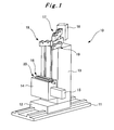
- a column base 12 is provided on a bed 11 movably in a horizontal direction (referred to as a front-rear direction for convenience), and a column 13 stands on the column base 12.
- a saddle 14 is supported on one of the side surfaces of the column 13 movably in the vertical direction (referred to as a top-bottom direction for convenience), and a ram 15 is supported on the saddle 14 movably in a horizontal direction (referred to as a left-right direction for convenience).
- the ram 15 includes a spindle, and a machining target workpiece is machined using a tool attached to the front end of the spindle. In machining, the column base 12, the saddle 14, and the ram 15 are moved in the front-rear direction, the top-bottom direction, and the left-right direction, respectively, to perform a desired machining.
- Fig. 1 omits the illustration of a counterweight 33 (first counterweight) and chains 34
- the saddle 14 is coupled to a counterweight 33 through two pulleys 19 and two chains 34.
- the ram 15 is coupled to the center of gravity of the counterweight 33 through a suspension structure 16, chains 32, and a swing arm 17.
- a shift in the center of gravity of the whole machine is prevented by a moment balance counterweight 18 (second counterweight) provided to the swing arm 17.
- the counterweight 33 has the same weight as that of the saddle 14 and the ram 15 and is provided inside the column 13.
- the counterweight 33 is used to suspend the saddle 14 and the ram 15.
- the saddle 14 constrains the ram 15 at the four side surfaces thereof (four-surface constraint) to provide a structure further increasing the rigidity of the ram 15.
- a ram balance beam 21 is provided in the upper surface of the ram 15, and the ram balance beam 21 is supported at two Bessel points 15a on the ram 15.
- the thickness of the ram balance beam 21 is increased so that the ram balance beam 21 can handle shifts in the center of gravity of the ram 15 (more specifically, handle a shift in the center of gravity depending upon whether an attachment is mounted or not and handle a shift in the center of gravity by each attachment).
- a guide block 22a (first guide block) and a guide block 22b (third guide block) are fixed to the upper surface of the thicker portion of the ram balance beam 21 having a trapezoidal cross section.
- the guide blocks 22a and 22b are supported movably on a guide rail 23 (first guide rail).
- the guide blocks 22a and 22b are configured to be moved on the guide rail 23 along with the feeding of the ram 15 (see Fig. 3 ).
- the guide rail 23 is connected through multiple beams 24 to the other guide rail 25 (second guide rail) disposed on the upper surface of the saddle 14.
- a guide block 26 (second guide block) supported movably on the guide rail 25 is coupled to the chains 32 through a support arm 31, and coupled to the counterweight 33 through the chains 32.
- the saddle 14 is provided with through-holes only at the positions of the beams 24 connecting the guide rail 23 and the guide rail 25, and the suspension structure 16 is disposed in a state of floating inside the saddle 14.
- the suspension structure 16 is formed of the guide blocks 22a and 22b, the guide rail 23, the beams 24, the guide rail 25, and the guide block 26 and has a structure in which a first linear guide (the guide blocks 22a and 22b and the guide rail 23) inside the saddle 14 and a second linear guide (the guide block 26 and the guide rail 25) outside the saddle 14 are connected by the multiple beams 24.
- the saddle 14 constrains the four side surfaces of the ram 15, and no opening portion can therefore be provided to an upper portion of the ram 15.
- the chains 32 suspending the guide block 26 as a suspending point and the ram balance beam 21 directly supporting the ram 15 are connected to each other, and the ram 15 inside the saddle 14 can therefore be suspended by the chains 32.
- a suspending position moving device 20 to be described later can be installed outside the saddle 14.
- the guide block 22a mentioned above is for a case where no attachment is present at the front end of the ram 15.
- the position of the guide block 26 is disposed directly above the guide block 22a so that the ram 15 may be supported by using the guide block 22a.
- the guide block 26 is disposed directly above the guide block 22a, and the ram 15 is suspended at a suspending position G in Fig. 2 by the chains 32 through the suspension structure 16.
- the guide block 26 is likewise disposed directly above the guide block 22a in synchronization with the moved position of the guide block 22a, and the ram 15 is suspended at a suspending position Ga in Fig.
- the guide block 22a the center of gravity of the ram 15 itself, and the guide block 26 is moved to the position directly above the center of gravity in synchronization with the center of gravity moved along with the feeding of the ram 15.
- the guide block 22b mentioned above is for a case where an attachment with the maximum weight is present at the front end of the ram 15.
- the position of the guide block 26 is disposed directly above the guide block 22b so that the ram 15 may be supported by using the guide block 22b. While the ram 15 is not fed, then in Fig. 2 , the guide block 26 is disposed directly above the guide block 22b though the illustration thereof is omitted, and the ram 15 is suspended by the chains 32 through the suspension structure 16.
- the guide block 26 is likewise disposed directly above the guide block 22b in synchronization with the moved position of the guide block 22b, and the ram 15 is suspended at a suspending position Gb in Fig. 3 by the chains 32 through the suspension structure 16.
- the guide block 22b the center of gravity of the ram 15 with the attachment, and the guide block 26 is moved to the position directly above the center of gravity in synchronization with the center of gravity moved along with the feeding of the ram 15.
- the position of the guide block 26 is disposed directly above a center of gravity which corresponds to the weight of the mounted attachment and exists between the guide block 22a and the guide block 22b.
- the guide block 26 is disposed directly above the center of gravity in synchronization with the amount of the feeding of the ram 15, and the ram 15 is suspended by the chains 32 through the suspension structure 16.
- the ram 15 is suspended in a state where the weight is distributed to the guide block 22a and the guide block 22b.
- the suspending position moving device 20 configured to move the guide block 26 in synchronization with the feeding of the ram 15 is provided along the guide rail 25.
- the suspending position moving device 20 includes a servomotor Ma, a ball screw 28 rotationally driven by the servomotor Ma, and a movable member 27 provided to be movable on the ball screw 28 along with the rotation of the ball screw 28.
- the movable member 27 and the guide block 26 are connected to each other, and the servomotor Ma is driven and controlled such that the guide block 26 can be moved together with the movable member. By such control, the guide block 26 is moved and the suspending position is thus moved in synchronization with the feeding of the ram 15.
- the suspending position moving device 20 is configured to also perform control on the moving of the position of the guide block 26 due to the mounting of an attachment, i.e. control for handling a shift in the center of gravity of the ram 15 due to the mounting of an attachment.
- control for handling a shift in the center of gravity of the ram 15 due to the mounting of an attachment i.e. control for handling a shift in the center of gravity of the ram 15 due to the mounting of an attachment.
- the position of the guide block 26 is set directly above the guide block 22a; in the case where an attachment with the maximum weight is present, the position of the guide block 26 is set directly above the guide block 22b; and in the case where an attachment of some other type with a weight which is not the maximum weight is mounted, the position of the guide block 26 is set directly above the center of gravity in a state where the attachment of some other type is mounted. Accordingly, it is possible to handle various multiple types of attachments and control the suspending position to a given position based on the type and the like.
- a coupling structure 40 including a hydraulic cylinder 42 may be used to move the center of gravity of the ram 15 and change the suspending position for each attachment, as will be explained in later-described Embodiment 2 (see Figs. 10 to 15 , etc).
- a counterweight moving device 30 configured to swing the swing arm 17 and thus move the counterweight 18 in synchronization with the feeding of the ram 15 is also provided on the column 13.
- the counterweight moving device 30 includes a servomotor Mb, a ball screw 37 rotationally driven by the servomotor Mb, a guide block 36 provided to be capable of moving on the ball screw 37 along with the rotation of the ball screw 37, and a guide rail 35 on which the guide block 36 is supported movably.
- the guide block 36 and the swing arm 17 are coupled to each other, and the servomotor Mb is driven and controlled such that the swing arm 17 can be swung together with the guide block 36.
- the swing arm 17 is swung to move the counterweight 18 in the direction opposite to the feeding direction of the ram 15 in synchronization with the feeding of the ram 15, so as to prevent a shift in the center of gravity of the whole machine.
- step S1 the presence or absence of an attachment at the front end of the ram 15 is detected. Then, the process proceeds to step S2 if an attachment is present, while the process proceeds to step S5 if no attachment is present.
- step S2 If an attachment is present, the type of the attachment is checked (step S2). Then, a correction value corresponding to the amount of the shift in the center of gravity due to the attachment is calculated (step S3). Thereafter, the servomotor Ma is driven based on the correction value to move the suspending position to the position corresponding to the new center of gravity (step S4).
- a suspending position moving amount a (step S5; see also reference numeral a in Fig. 7 ) is instructed, and the servomotor Ma is driven to move the suspending position in synchronization with the position to which the ram 15 is fed (step S6).
- step S11 the suspending position moving amount a instructed in step S5 described above is checked (step S11). Then, a moving amount b in the counterweight moving device 30 corresponding to the suspending position moving amount a is calculated (step S12; see also reference numeral b in Fig. 7 ).
- the servomotor Mb is driven to swing the swing arm 17 in synchronization with the position to which the ram 15 is fed, so that the guide block 36, i.e. the counterweight 18 is moved to a position which is point-symmetrical to the position of the guide block 26. Moving the counterweight 18 in this manner prevents a shift in the center of gravity of the horizontal boring machine 10.
- the horizontal boring machine 10 with the ram 15 constraining the four surfaces of the saddle 14 can secure a high rigidity for the ram 15 and achieve a perfect balancer allowing no shift in the center of gravity of the whole machine.
- a change in weight balance due to a horizontal movement of the ram 15 and a change in weight balance caused when an attachment is attached to the front end of the ram 15 are handled.
- a ram-type horizontal boring machine 10' shown in Fig. 10 differs from the horizontal boring machine 10 shown in Fig. 1 in a structure around the suspension structure 16.
- the other structures including the structure of the suspension structure 16 are the same; therefore, the same reference numerals are given thereto, and overlapping descriptions are omitted.
- the horizontal boring machine 10' is one in which the suspending position moving device 20 is removed from the horizontal boring machine 10 shown in Fig. 1 , and the aforementioned coupling structure 40 coupling the guide block 26 and the ram 15 to each other is provided instead.
- the coupling structure 40 is configured to couple the guide block 26 and the ram 15 to each other as mentioned above, and includes: a connecting member 41 fixed to the guide block 26 and being capable of moving on the guide rail 25 together with the guide block 26; a hydraulic cylinder 42 attached to the connecting member 41 and configured to extend and retract in the same direction as the moving direction of the guide block 26; a bracket 43 attached to the hydraulic cylinder 42 and extending in the same direction as the moving direction of the guide block 26; a bracket 44 attached to the upper surface of the ram 15 and extending in the same direction as the moving direction of the ram 15; and a coupling bracket 45 coupling the bracket 43 and the bracket 44 to each other.
- the coupling structure 40 is a structure substantially coupling the guide block 26 and the guide blocks 22a and 22b to each other and configured to move the guide block 26 in synchronization with the feeding of the ram 15.
- the suspending position moving device 20 is used to move the guide block 26 in synchronization with the feeding of the ram 15.
- the coupling structure 40 is provided, allowing the guide block 26 to move in synchronization with the feeding of the ram 15 with a simpler configuration.
- the bracket 44 is configured to be moved to a position underneath the guide rail 23 when the ram 15 is fed, and therefore has such a thickness that the bracket 44 will not interfere with the guide rail 23.
- the connecting member 41, the hydraulic cylinder 42, and the bracket 43 are configured to be moved on the guide rail 25 together with the guide block 26, and their lower surfaces are therefore at such a position that the lower surfaces will not interfere with the guide rail 25.
- the coupling bracket 45 is disposed rearward of the rear end of the ram 15 so that the coupling bracket 45 will not interfere with the suspension structure 16 and the saddle 14 even when the ram 15 is fed to the maximum extent, and the lengths of the bracket 43 and the bracket 44 are so set as to obtain such an arrangement.
- the bracket 43, the coupling bracket 45, and the bracket 44 are arranged in a substantially U shape and are coupled to the guide block 26 through the hydraulic cylinder 42.
- the hydraulic cylinder 42 is in a fully retracted state, and the guide block 26 is moved in synchronization with the feeding of the ram 15 while maintaining this state (see G in Fig. 11 and Ga in Fig. 12 , for example).
- proximity sensors are provided on the outer circumference of the hydraulic cylinder 42 on the basis of the positions of the center of gravity corresponding to each of attachments.
- the proximity sensors are used to control the amount of the extension of the hydraulic cylinder 42 on the basis of the attachment and change the suspending position on an attachment basis to handle a shift in the center of gravity of the ram 15. Accordingly, it is possible to handle various multiple types of attachments and change the suspending position to a given position based on the type and the like.
- the servomotor Mb is driven and controlled such that the swing arm 17 can be swung to move the counterweight 18 in the direction opposite to the direction of the feeding of the ram 15 in synchronization with the feeding of the ram 15, so as to prevent a shift in the center of gravity of the whole machine.
- step S21 the presence or absence of an attachment at the front end of the ram 15 is detected. Then, the process proceeds to step S22 if an attachment is present, while the process proceeds to step S25 if no attachment is present.
- step S22 If an attachment is present, the type of the attachment is checked (step S22). Then, a correction value corresponding to the amount of the shift in the center of gravity due to the attachment is calculated (step S23). Thereafter, the hydraulic cylinder 42 is driven by using the proximity sensor corresponding to the correction value to move the suspending position to the position corresponding to the new center of gravity (step S24).
- a suspending position moving amount a (step S25; see also reference numeral a in Fig. 14 ) is instructed, and the ram 15 is fed accordingly.
- the position of the guide block 26, i.e. the suspending position is spontaneously moved in synchronization with the amount of the feeding of the ram 15.
- step S25 the suspending position moving amount a instructed in step S25 described above is checked. Then, a moving amount b in the counterweight moving device 30 corresponding to the suspending position moving amount a is calculated (step S26; see also reference numeral b in Fig. 14 ).
- the servomotor Mb is driven (step S27) to swing the swing arm 17 in synchronization with the position to which the ram 15 is fed, so that the guide block 36, i.e. the counterweight 18 is moved to a position which is point-symmetrical to the position of the guide block 26. Moving the counterweight 18 in this manner prevents a shift in the center of gravity of the horizontal boring machine 10'.
- the horizontal boring machine 10' with the ram 15 constraining the four surfaces of the saddle 14 can secure a high rigidity for the ram 15 and achieve a perfect balancer allowing no shift in the center of gravity of the whole machine with a simpler configuration.
- a change in weight balance due to a horizontal movement of the ram 15 and a change in weight balance caused when an attachment is attached to the front end of the ram 15 are handled.
- the present invention is suitable for ram-type horizontal boring machines and the like.
Landscapes
- Engineering & Computer Science (AREA)
- Mechanical Engineering (AREA)
- Drilling And Boring (AREA)
- Machine Tool Units (AREA)
Abstract
Description
- The present invention relates to a balancer of a machine tool such as a horizontal boring machine and to a balance control method.
-
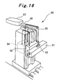
Fig. 16 shows a conventional balancer of a machine tool.
The machine tool shown inFig. 16 is a ram-stock-typehorizontal boring machine 50. In thehorizontal boring machine 50, aram stock 51 is supported at two spots as Bessel points thereof by anarm 53, and thearm 53 is suspended at the center of gravity thereof by achain 55. Thechain 55 is coupled to the center of gravity of acounterweight 54 through aswing arm 56. When theram stock 51 is moved in its feeding direction, theswing arm 56, which is provided with amoment balance counterweight 57, is swung to move thecounterweight 57 in the direction opposite to the feeding direction in synchronization with the movement so as to prevent a shift in the center of gravity of the whole machine. Moreover, in a case where an attachment is mounted to the front surface of theram stock 51, a suspending position moving device (unillustrated) provided to thearm 53 corrects the suspending position on the basis of the center of gravity of theram stock 51 with the attachment. - Patent Document 1: Japanese Patent Application Publication No.
2009-131924 - Patent Document 2: Japanese Examined Patent Application Publication No.
Hei 03-064264 - Patent Document 3: Japanese Examined Patent Application Publication No.
Sho 58-041965 - Patent Document 4: Japanese Examined Patent Application Publication No.
Sho 62-047125 - The above-described balancer is applicable to the ram-stock-type
horizontal boring machine 50 in which asaddle 52 constrains part of the side surfaces of theram stock 51, and the upper surface of theram stock 51 is open as shown inFig. 16 . However, the above-described balancer is not applicable as is to a ram-typehorizontal boring machine 60 in which asaddle 62 constrains the four side surfaces of theram 61 as shown inFig. 17 . - The balancer shown in
Fig. 16 has various advantages as follows: since the center of gravity around the column is even, the column does not fall down; since the ram is suspended at the center of gravity thereof, ran slide does not affect deformation of the ram; since the center of gravity of the ram can be corrected on an attachment basis, deformation of the ram is small, and thus the feeding accuracy is improved; since the supporting force on each sliding surface of the ram is even, the sliding portion does not wear unevenly, and thus a stable accuracy is maintained for a long period of time; and so on. On the other hand, the ram-typehorizontal boring machine 60 shown inFig. 17 has an advantage that theram 61 can secure a high rigidity since thesaddle 62 constrains the four side surfaces of theram 61. Accordingly, the straightness of the spindle can be improved further greatly if the above-described balancer can be applied to the ram-typehorizontal boring machine 60 shown inFig. 17 , and such application of the above-described balancer has been desired. - The present invention has been made in view of the above-described problem, and an object thereof is to provide a machine tool balancer applicable to a ram-type horizontal boring machine and a balance control method.
- A machine tool balancer according to a first invention for solving the above problem comprises:
- a saddle constraining four side surfaces of a ram in such a way that the ram is horizontally movable;
- a first counterweight having a same weight as a weight of the ram and the saddle, coupled to the ram and the saddle, and suspending the ram and the saddle;
- a second counterweight configured to be moved on the basis of an amount of feeding of the ram to prevent a shift in a position of the center of gravity of the machine tool;
- a suspension structure including a first linear guide and a second linear guide, the first linear guide including a first guide block and a first guide rail disposed inside the saddle, the second linear guide including a second guide block and a second guide rail disposed outside the saddle, the first guide block being fixed to an upper surface of the ram above a center of gravity of the ram, the first guide rail and the second guide rail being connected to each other, the first counterweight and the second counterweight being coupled to the second guide block;
- a suspending position moving device configured to move the second guide block to a position directly above the first guide block in synchronization with a position of the first guide block which is moved along with the feeding of the ram (in other words, the first guide block = the center of gravity of the ram, and the second guide block is moved to the position directly above the center of gravity in synchronization with the center of gravity moved along with the feeding of the ram); and
- a counterweight moving device configured to move the second counterweight to a position point-symmetrical to the position of the second guide block.
- A machine tool balancer according to a second invention for solving the above problem is that wherein
in the machine tool balancer according to the first invention,
a third guide block movably supported on the first guide rail is provided on an upper surface of the ram corresponding to and above a center of gravity of the ram in a state where an attachment with a maximum weight is mounted to the ram, and
in a case where an attachment is mounted to the ram, the suspending position moving device moves the second guide block, on the basis of a center of gravity of the ram which corresponds to a weight of the mounted attachment and exists between the first guide block and the third guide block, to a position directly above the center of gravity in synchronization with the center of gravity which is moved along with the feeding of the ram. - A machine tool balancer according to a third invention for solving the above problem is that wherein
in the machine tool balancer according to the second invention,
in the case where the attachment with the maximum weight is mounted to the ram, the suspending position moving device moves the second guide block to a position directly above the third guide block in synchronization with a position of the third guide block which is moved along with the feeding of the ram (in other words, the third guide block = the center of gravity of the ram with the attachment, and the second guide block is moved to the position directly above the center of gravity in synchronization with the center of gravity moved along with the feeding of the ram). - A machine tool balancer according to a fourth invention for solving the above problem comprises:
a saddle constraining four side surfaces of a ram in such a way that the ram is horizontally movable;
a first counterweight having a same weight as a weight of the ram and the saddle, coupled to the ram and the saddle, and suspending the ram and the saddle;
a second counterweight configured to be moved on the basis of an amount of feeding of the ram to prevent a shift in a center of gravity of the machine tool;
a suspension structure including a first linear guide and a second linear guide, the first linear guide including a first guide block and a first guide rail disposed inside the saddle, the second linear guide including a second guide block and a second guide rail disposed outside the saddle, the first guide block being fixed to an upper surface of the ram above a center of gravity of the ram, the first guide rail and the second guide rail being connected to each other, the first counterweight and the second counterweight being coupled to the second guide block;
a coupling structure including a bracket coupling the ram and the second guide block without interfering with the saddle and the suspension structure, and configured to move the second guide block by means of the bracket to a position directly above the first guide block in synchronization with a position of the first guide block which is moved along with the feeding of the ram; and
a counterweight moving device configured to move the second counterweight to a position point-symmetrical to the position of the second guide block. - A machine tool balancer according to a fifth invention for solving the above problem is that wherein
in the machine tool balancer according to the fourth invention,
a third guide block movably supported on the first guide rail is provided on an upper surface of the ram corresponding to and above a center of gravity of the ram in a state where an attachment with a maximum weight is mounted to the ram,
a hydraulic cylinder is provided between the second guide block and the bracket, and
in a case where an attachment is mounted to the ram, the hydraulic cylinder moves the second guide block, on the basis of a center of gravity of the ram which corresponds to a weight of the mounted attachment and exists between the first guide block and the third guide block, to a position directly above the center of gravity. - A machine tool balancer according to a sixth invention for solving the above problem is that wherein
in the machine tool balancer according to the fifth invention,
in the case where the attachment with the maximum weight is mounted to the ram, the hydraulic cylinder moves the second guide block to a position directly above the third guide block. - A method of controlling balance of a machine tool according to a seventh invention for solving the above problem includes
a saddle constraining four side surfaces of a ram in such a way that the ram is horizontally movable,
a first counterweight having a same weight as a weight of the ram and the saddle, coupled to the ram and the saddle, and suspending the ram and the saddle,
a second counterweight configured to be moved on the basis of an amount of feeding of the ram to prevent a shift in a center of gravity of the machine tool, and
a suspension structure including a first linear guide and a second linear guide, the first linear guide including a first guide block and a first guide rail disposed inside the saddle, the second linear guide including a second guide block and a second guide rail disposed outside the saddle, the first guide block being fixed to an upper surface of the ram above a center of gravity of the ram, the first guide rail and the second guide rail being connected to each other, the first counterweight and the second counterweight being coupled to the second guide block. The method comprises: - moving the second guide block to a position directly above the first guide block in synchronization with a position of the first guide block which is moved along with the feeding of the ram; and
- moving the second counterweight to a position point-symmetrical to the position of the second guide block.
- A method of controlling balance of a machine tool according to an eighth invention for solving the above problem is that wherein
in the method of controlling balance of a machine tool according to the seventh invention,
a third guide block movably supported on the first guide rail is further provided on an upper surface of the ram corresponding to and above a center of gravity of the ram in a state where an attachment with a maximum weight is mounted to the ram, and
in a case where an attachment is mounted to the ram, the second guide block is moved, on the basis of a center of gravity of the ram which corresponds to a weight of the mounted attachment and exists between the first guide block and the third guide block, to a position directly above the center of gravity in synchronization with the center of gravity which is moved along with the feeding of the ram. - A method of controlling balance of a machine tool according to a ninth invention for solving the above problem is that wherein
in the method of controlling balance of a machine tool according to the eighth invention,
in the case where the attachment with the maximum weight is mounted to the ram, the second guide block is moved to a position directly above the third guide block in synchronization with a position of the third guide block which is moved along with the feeding of the ram. - A method of controlling balance of a machine tool according to a tenth invention for solving the above problem includes
a saddle constraining four side surfaces of a ram in such a way that the ram is horizontally movable,
a first counterweight having a same weight as a weight of the ram and the saddle, coupled to the ram and the saddle, and suspending the ram and the saddle,
a second counterweight configured to be moved on the basis of an amount of feeding of the ram to prevent a shift in a center of gravity of the machine tool,
a suspension structure including a first linear guide and a second linear guide, the first linear guide including a first guide block and a first guide rail disposed inside the saddle, the second linear guide including a second guide block and a second guide rail disposed outside the saddle, the first guide block being fixed to an upper surface of the ram above a center of gravity of the ram, the first guide rail and the second guide rail being connected to each other, the first counterweight and the second counterweight being coupled to the second guide block, and
a coupling structure including a bracket coupling the ram and the second guide block without interfering with the saddle and the suspension structure, the coupling structure being configured to move the second guide block by means of the bracket to a position directly above the first guide block in synchronization with a position of the first guide block which is moved along with the feeding of the ram. The method comprises
moving the second counterweight to a position point-symmetrical to the position of the second guide block. - A method of controlling balance of a machine tool according to an eleventh invention for solving the above problem is that wherein
in the method of controlling balance of a machine tool according to the tenth invention,
a third guide block movably supported on the first guide rail is further provided on an upper surface of the ram corresponding to and above a center of gravity of the ram in a state where an attachment with a maximum weight is mounted to the ram,
a hydraulic cylinder is provided between the second guide block and the bracket, and
in a case where an attachment is mounted to the ram, the hydraulic cylinder moves the second guide block on the basis of a center of gravity of the ram, which corresponds to a weight of the mounted attachment and exists between the first guide block and the third guide block, to a position directly above the center of gravity. - A method of controlling balance of a machine tool according to a twelfth invention for solving the above problem is that wherein
in the method of controlling balance of a machine tool according to the eleventh invention,
in the case where the attachment with the maximum weight is mounted to the ram, the hydraulic cylinder moves the second guide block to a position directly above the third guide block. - According to the present invention, a balancer can be provided to a ram-type horizontal boring machine since a suspension structure configured to suspend a ram constrained at the four surfaces thereof by a saddle is provided. Thus, by the balancer provided to the ram-type horizontal boring machine, a shift in the center of gravity of the whole machine can be prevented. As a result, a change in weight balance due to a horizontal movement of the ram and a change in weight balance caused when any of attachments of various types is attached to the front end of the ram are handled. This suppresses displacement and deformation originating from the changes in weight balance. Accordingly, the straightness of highly rigid rams can be improved.
-
- [
Fig. 1] Fig. 1 is a perspective view of a machine tool including a balancer according to the present invention. - [
Fig. 2] Fig. 2 is a cross-sectional view of a suspension structure, a ram, and a saddle according to the present invention in a state where the ram is not yet fed. - [
Fig. 3] Fig. 3 is a cross-sectional view of the suspension structure, the ram, and the saddle according to the present invention in a state where the ram is fed. - [
Fig. 4] Fig. 4 is a perspective view showing the suspension structure according to the present invention. - [
Fig. 5] Fig. 5 is a view of the suspension structure, the ram, and the saddle according to the present invention as seen from a front side of the machine tool. - [
Fig. 6] Fig. 6 is a view of the suspension structure, the ram, and the saddle according to the present invention as seen from a lateral side of the machine tool. - [
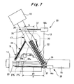
Fig. 7] Fig. 7 is a view of the balancer, the ram, and the saddle according to the present invention as seen from a top side of the machine tool. - [
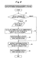
Fig. 8] Fig. 8 is a flowchart describing ram/suspending-position movement control according to the present invention. - [
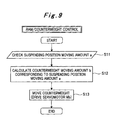
Fig. 9] Fig. 9 is a flowchart describing ram/counterweight control according to the present invention. - [
Fig. 10] Fig. 10 is a perspective view of a machine tool including a balancer according a different embodiment of the present invention. - [
Fig. 11] Fig. 11 is a cross-sectional view of a suspension structure, a ram, and a saddle according to the different embodiment of the present invention in a state where the ram is not yet fed. - [
Fig. 12] Fig. 12 is a cross-sectional view of the suspension structure, the ram, and the saddle according to the different embodiment of the present invention in a state where the ram is fed. - [
Fig. 13] Fig. 13 is a view of the suspension structure, the ram, and the saddle according to the different embodiment of the present invention as seen from a lateral side of the machine tool. - [
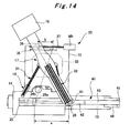
Fig. 14] Fig. 14 is a view of the balancer, the ram, and the saddle according to the different embodiment of the present invention as seen from a top side of the machine tool. - [
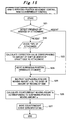
Fig. 15] Fig. 15 is a flowchart describing ram/suspending-position movement control and ram/counterweight control according to the different embodiment of the present invention. - [
Fig. 16] Fig. 16 is a perspective view showing a balancer of a ram-stock-type horizontal boring machine. - [
Fig. 17] Fig. 17 is a perspective view showing a ram-type horizontal boring machine. -
- 10, 10'
- horizontal boring machine
- 14
- saddle
- 15
- ram
- 16
- suspension structure
- 17
- swing arm
- 18
- counterweight (for balancing moment)
- 20
- suspending position moving device
- 21
- ram balance beam
- 22a, 22b
- uide block
- 23
- guide rail
- 24
- beam
- 25
- guide rail
- 26
- guide block
- 30
- counterweight moving device
- 33
- counterweight (for balancing ram' and saddle's weights)
- 40
- coupling structure
- 42
- hydraulic cylinder
- Hereinbelow, a machine tool balancer and a balance control method according to the present invention will be described with reference to
Figs. 1 to 15 . - In a ram-type
horizontal boring machine 10 shown inFig. 1 , acolumn base 12 is provided on abed 11 movably in a horizontal direction (referred to as a front-rear direction for convenience), and acolumn 13 stands on thecolumn base 12. Asaddle 14 is supported on one of the side surfaces of thecolumn 13 movably in the vertical direction (referred to as a top-bottom direction for convenience), and aram 15 is supported on thesaddle 14 movably in a horizontal direction (referred to as a left-right direction for convenience). Theram 15 includes a spindle, and a machining target workpiece is machined using a tool attached to the front end of the spindle. In machining, thecolumn base 12, thesaddle 14, and theram 15 are moved in the front-rear direction, the top-bottom direction, and the left-right direction, respectively, to perform a desired machining. - To explain with reference to
Fig. 1 and alsoFig. 7 sinceFig. 1 omits the illustration of a counterweight 33 (first counterweight) andchains 34, thesaddle 14 is coupled to acounterweight 33 through twopulleys 19 and twochains 34. Moreover, to explain with reference toFig. 1 and alsoFig. 7 sinceFig. 1 omits the illustration ofchains 32, theram 15 is coupled to the center of gravity of thecounterweight 33 through asuspension structure 16,chains 32, and aswing arm 17. A shift in the center of gravity of the whole machine is prevented by a moment balance counterweight 18 (second counterweight) provided to theswing arm 17. Thecounterweight 33 has the same weight as that of thesaddle 14 and theram 15 and is provided inside thecolumn 13. Thecounterweight 33 is used to suspend thesaddle 14 and theram 15. - Now, the
suspension structure 16 will be described with reference toFigs. 2 to 6 . Note that although various structural components are provided inside thesaddle 14 and theram 15,Figs. 2 and3 omit the illustration thereof for the sake of simplicity in the drawings and explanation. - In this embodiment, the
saddle 14 constrains theram 15 at the four side surfaces thereof (four-surface constraint) to provide a structure further increasing the rigidity of theram 15. In addition, aram balance beam 21 is provided in the upper surface of theram 15, and theram balance beam 21 is supported at two Bessel points 15a on theram 15. The thickness of theram balance beam 21 is increased so that theram balance beam 21 can handle shifts in the center of gravity of the ram 15 (more specifically, handle a shift in the center of gravity depending upon whether an attachment is mounted or not and handle a shift in the center of gravity by each attachment). Aguide block 22a (first guide block) and aguide block 22b (third guide block) are fixed to the upper surface of the thicker portion of theram balance beam 21 having a trapezoidal cross section. - The guide blocks 22a and 22b are supported movably on a guide rail 23 (first guide rail). The guide blocks 22a and 22b are configured to be moved on the
guide rail 23 along with the feeding of the ram 15 (seeFig. 3 ). Meanwhile, theguide rail 23 is connected throughmultiple beams 24 to the other guide rail 25 (second guide rail) disposed on the upper surface of thesaddle 14. A guide block 26 (second guide block) supported movably on theguide rail 25 is coupled to thechains 32 through asupport arm 31, and coupled to thecounterweight 33 through thechains 32. Note that thesaddle 14 is provided with through-holes only at the positions of thebeams 24 connecting theguide rail 23 and theguide rail 25, and thesuspension structure 16 is disposed in a state of floating inside thesaddle 14. - As described, the
suspension structure 16 is formed of the guide blocks 22a and 22b, theguide rail 23, thebeams 24, theguide rail 25, and theguide block 26 and has a structure in which a first linear guide (the guide blocks 22a and 22b and the guide rail 23) inside thesaddle 14 and a second linear guide (theguide block 26 and the guide rail 25) outside thesaddle 14 are connected by the multiple beams 24. - In this embodiment, the
saddle 14 constrains the four side surfaces of theram 15, and no opening portion can therefore be provided to an upper portion of theram 15. However, by providing thesuspension structure 16, thechains 32 suspending theguide block 26 as a suspending point and theram balance beam 21 directly supporting theram 15 are connected to each other, and theram 15 inside thesaddle 14 can therefore be suspended by thechains 32. Moreover, by providing thesuspension structure 16, a suspendingposition moving device 20 to be described later can be installed outside thesaddle 14. - The
guide block 22a mentioned above is for a case where no attachment is present at the front end of theram 15. In the case where no attachment is present at the front end of theram 15, the position of theguide block 26 is disposed directly above theguide block 22a so that theram 15 may be supported by using theguide block 22a. While theram 15 is not fed, theguide block 26 is disposed directly above theguide block 22a, and theram 15 is suspended at a suspending position G inFig. 2 by thechains 32 through thesuspension structure 16. Moreover, while theram 15 is fed, theguide block 26 is likewise disposed directly above theguide block 22a in synchronization with the moved position of theguide block 22a, and theram 15 is suspended at a suspending position Ga inFig. 3 by thechains 32 through thesuspension structure 16. In other words, theguide block 22a = the center of gravity of theram 15 itself, and theguide block 26 is moved to the position directly above the center of gravity in synchronization with the center of gravity moved along with the feeding of theram 15. - In contrast, the
guide block 22b mentioned above is for a case where an attachment with the maximum weight is present at the front end of theram 15. In the case where the attachment with the maximum weight is present at the front end of theram 15, the position of theguide block 26 is disposed directly above theguide block 22b so that theram 15 may be supported by using theguide block 22b. While theram 15 is not fed, then inFig. 2 , theguide block 26 is disposed directly above theguide block 22b though the illustration thereof is omitted, and theram 15 is suspended by thechains 32 through thesuspension structure 16. Moreover, while theram 15 is fed, theguide block 26 is likewise disposed directly above theguide block 22b in synchronization with the moved position of theguide block 22b, and theram 15 is suspended at a suspending position Gb inFig. 3 by thechains 32 through thesuspension structure 16. In other words, theguide block 22b = the center of gravity of theram 15 with the attachment, and theguide block 26 is moved to the position directly above the center of gravity in synchronization with the center of gravity moved along with the feeding of theram 15. - Moreover, in a case of mounting an attachment of some other type with a weight which is not the maximum weight, the position of the
guide block 26 is disposed directly above a center of gravity which corresponds to the weight of the mounted attachment and exists between theguide block 22a and theguide block 22b. In this case too, regardless of whether theram 15 is fed or theram 15 is not fed, theguide block 26 is disposed directly above the center of gravity in synchronization with the amount of the feeding of theram 15, and theram 15 is suspended by thechains 32 through thesuspension structure 16. In other words, in this case, theram 15 is suspended in a state where the weight is distributed to theguide block 22a and theguide block 22b. - In addition, the suspending
position moving device 20 configured to move theguide block 26 in synchronization with the feeding of theram 15 is provided along theguide rail 25. The suspendingposition moving device 20 includes a servomotor Ma, aball screw 28 rotationally driven by the servomotor Ma, and amovable member 27 provided to be movable on theball screw 28 along with the rotation of theball screw 28. Themovable member 27 and theguide block 26 are connected to each other, and the servomotor Ma is driven and controlled such that theguide block 26 can be moved together with the movable member. By such control, theguide block 26 is moved and the suspending position is thus moved in synchronization with the feeding of theram 15. - The suspending
position moving device 20 is configured to also perform control on the moving of the position of theguide block 26 due to the mounting of an attachment, i.e. control for handling a shift in the center of gravity of theram 15 due to the mounting of an attachment. As mentioned above, in the case where no attachment is present, the position of theguide block 26 is set directly above theguide block 22a; in the case where an attachment with the maximum weight is present, the position of theguide block 26 is set directly above theguide block 22b; and in the case where an attachment of some other type with a weight which is not the maximum weight is mounted, the position of theguide block 26 is set directly above the center of gravity in a state where the attachment of some other type is mounted. Accordingly, it is possible to handle various multiple types of attachments and control the suspending position to a given position based on the type and the like. - Note that instead of the suspending
position moving device 20, acoupling structure 40 including ahydraulic cylinder 42 may be used to move the center of gravity of theram 15 and change the suspending position for each attachment, as will be explained in later-described Embodiment 2 (seeFigs. 10 to 15 , etc). - Additionally, a
counterweight moving device 30 configured to swing theswing arm 17 and thus move thecounterweight 18 in synchronization with the feeding of theram 15 is also provided on thecolumn 13. Thecounterweight moving device 30 includes a servomotor Mb, aball screw 37 rotationally driven by the servomotor Mb, aguide block 36 provided to be capable of moving on theball screw 37 along with the rotation of theball screw 37, and aguide rail 35 on which theguide block 36 is supported movably. Theguide block 36 and theswing arm 17 are coupled to each other, and the servomotor Mb is driven and controlled such that theswing arm 17 can be swung together with theguide block 36. By such control, theswing arm 17 is swung to move thecounterweight 18 in the direction opposite to the feeding direction of theram 15 in synchronization with the feeding of theram 15, so as to prevent a shift in the center of gravity of the whole machine. - Now, ram/suspending-position movement control shown in
Fig. 8 and ram/counterweight control shown inFig. 9 will be described with reference toFig. 7 . - In the ram/suspending-position movement control shown in
Fig. 8 , firstly, the presence or absence of an attachment at the front end of theram 15 is detected (step S1). Then, the process proceeds to step S2 if an attachment is present, while the process proceeds to step S5 if no attachment is present. - If an attachment is present, the type of the attachment is checked (step S2). Then, a correction value corresponding to the amount of the shift in the center of gravity due to the attachment is calculated (step S3). Thereafter, the servomotor Ma is driven based on the correction value to move the suspending position to the position corresponding to the new center of gravity (step S4).
- Then, based on an instruction regarding the amount of the feeding of the
ram 15, a suspending position moving amount a (step S5; see also reference numeral a inFig. 7 ) is instructed, and the servomotor Ma is driven to move the suspending position in synchronization with the position to which theram 15 is fed (step S6). - On the other hand, in the ram/counterweight control shown in
Fig. 9 , the suspending position moving amount a instructed in step S5 described above is checked (step S11). Then, a moving amount b in thecounterweight moving device 30 corresponding to the suspending position moving amount a is calculated (step S12; see also reference numeral b inFig. 7 ). - Then, based on the calculated moving amount b, the servomotor Mb is driven to swing the
swing arm 17 in synchronization with the position to which theram 15 is fed, so that theguide block 36, i.e. thecounterweight 18 is moved to a position which is point-symmetrical to the position of theguide block 26. Moving thecounterweight 18 in this manner prevents a shift in the center of gravity of the horizontalboring machine 10. - By the above configuration, the horizontal
boring machine 10 with theram 15 constraining the four surfaces of thesaddle 14 can secure a high rigidity for theram 15 and achieve a perfect balancer allowing no shift in the center of gravity of the whole machine. As a result, a change in weight balance due to a horizontal movement of theram 15 and a change in weight balance caused when an attachment is attached to the front end of theram 15 are handled. This suppresses displacement and deformation originating from the changes in weight balance and prevents a shift in the center of gravity of the whole machine. Accordingly, the straightness of the highlyrigid ram 15 can be improved. - A ram-type horizontal boring machine 10' shown in
Fig. 10 differs from the horizontalboring machine 10 shown inFig. 1 in a structure around thesuspension structure 16. In the horizontal boring machine 10', however, the other structures including the structure of thesuspension structure 16 are the same; therefore, the same reference numerals are given thereto, and overlapping descriptions are omitted. - Specifically, as shown in
Fig. 10 , the horizontal boring machine 10' is one in which the suspendingposition moving device 20 is removed from the horizontalboring machine 10 shown inFig. 1 , and theaforementioned coupling structure 40 coupling theguide block 26 and theram 15 to each other is provided instead. - The structure and operation of the
coupling structure 40 will be described with reference also toFigs. 11 to 14 . Thecoupling structure 40 is configured to couple theguide block 26 and theram 15 to each other as mentioned above, and includes: a connectingmember 41 fixed to theguide block 26 and being capable of moving on theguide rail 25 together with theguide block 26; ahydraulic cylinder 42 attached to the connectingmember 41 and configured to extend and retract in the same direction as the moving direction of theguide block 26; abracket 43 attached to thehydraulic cylinder 42 and extending in the same direction as the moving direction of theguide block 26; abracket 44 attached to the upper surface of theram 15 and extending in the same direction as the moving direction of theram 15; and acoupling bracket 45 coupling thebracket 43 and thebracket 44 to each other. - In other words, the
coupling structure 40 is a structure substantially coupling theguide block 26 and the guide blocks 22a and 22b to each other and configured to move theguide block 26 in synchronization with the feeding of theram 15. InEmbodiment 1, the suspendingposition moving device 20 is used to move theguide block 26 in synchronization with the feeding of theram 15. In this embodiment, thecoupling structure 40 is provided, allowing theguide block 26 to move in synchronization with the feeding of theram 15 with a simpler configuration. - Note that the
bracket 44 is configured to be moved to a position underneath theguide rail 23 when theram 15 is fed, and therefore has such a thickness that thebracket 44 will not interfere with theguide rail 23. Moreover, the connectingmember 41, thehydraulic cylinder 42, and thebracket 43 are configured to be moved on theguide rail 25 together with theguide block 26, and their lower surfaces are therefore at such a position that the lower surfaces will not interfere with theguide rail 25. In addition, thecoupling bracket 45 is disposed rearward of the rear end of theram 15 so that thecoupling bracket 45 will not interfere with thesuspension structure 16 and thesaddle 14 even when theram 15 is fed to the maximum extent, and the lengths of thebracket 43 and thebracket 44 are so set as to obtain such an arrangement. In this embodiment, thebracket 43, thecoupling bracket 45, and thebracket 44 are arranged in a substantially U shape and are coupled to theguide block 26 through thehydraulic cylinder 42. - In a case where no attachment is mounted to the front end of the
ram 15, thehydraulic cylinder 42 is in a fully retracted state, and theguide block 26 is moved in synchronization with the feeding of theram 15 while maintaining this state (see G inFig. 11 and Ga inFig. 12 , for example). In this case, theguide block 26 is disposed at a position directly above theguide block 22a (= the center of gravity of the ram 15) that corresponds to the center of gravity of theram 15 itself. - In contrast, in a case where an attachment is mounted to the front end of the
ram 15, the amount of the extension of thehydraulic cylinder 42 is controlled based on the mounted attachment, and theguide block 26 is moved in synchronization with the feeding of theram 15 while maintaining this state. In this case, the center of gravity of thewhole ram 15 with the attachment exists between theguide block 22a and theguide block 22b, and theguide block 26 is disposed directly above this center of gravity. Also, in a case where an attachment with the maximum weight is mounted, the amount of the extension of thehydraulic cylinder 42 is so controlled that theguide block 26 is disposed directly above theguide block 22b (= the center of gravity of theram 15 with the attachment with the maximum weight), and theguide block 26 is moved in synchronization with the feeding of theram 15 while maintaining this state (see Gb inFig. 12 , for example). - Multiple proximity sensors (unillustrated) are provided on the outer circumference of the
hydraulic cylinder 42 on the basis of the positions of the center of gravity corresponding to each of attachments. In controlling the amount of the extension of thehydraulic cylinder 42, the proximity sensors are used to control the amount of the extension of thehydraulic cylinder 42 on the basis of the attachment and change the suspending position on an attachment basis to handle a shift in the center of gravity of theram 15. Accordingly, it is possible to handle various multiple types of attachments and change the suspending position to a given position based on the type and the like. - As in the case of
Embodiment 1, in thecounterweight moving device 30, the servomotor Mb is driven and controlled such that theswing arm 17 can be swung to move thecounterweight 18 in the direction opposite to the direction of the feeding of theram 15 in synchronization with the feeding of theram 15, so as to prevent a shift in the center of gravity of the whole machine. - Now, ram/suspending-position movement control and counterweight control shown in
Fig. 15 will be described with reference toFig. 14 . - First, the presence or absence of an attachment at the front end of the
ram 15 is detected (step S21). Then, the process proceeds to step S22 if an attachment is present, while the process proceeds to step S25 if no attachment is present. - If an attachment is present, the type of the attachment is checked (step S22). Then, a correction value corresponding to the amount of the shift in the center of gravity due to the attachment is calculated (step S23). Thereafter, the
hydraulic cylinder 42 is driven by using the proximity sensor corresponding to the correction value to move the suspending position to the position corresponding to the new center of gravity (step S24). - Then, based on an instruction regarding the amount of the feeding of the
ram 15, a suspending position moving amount a (step S25; see also reference numeral a inFig. 14 ) is instructed, and theram 15 is fed accordingly. In this event, since theram 15 and theguide block 26 are coupled by thecoupling structure 40, the position of theguide block 26, i.e. the suspending position is spontaneously moved in synchronization with the amount of the feeding of theram 15. - On the other hand, in the
counterweight moving device 30, the suspending position moving amount a instructed in step S25 described above is checked. Then, a moving amount b in thecounterweight moving device 30 corresponding to the suspending position moving amount a is calculated (step S26; see also reference numeral b inFig. 14 ). - Then, based on the calculated moving amount b, the servomotor Mb is driven (step S27) to swing the
swing arm 17 in synchronization with the position to which theram 15 is fed, so that theguide block 36, i.e. thecounterweight 18 is moved to a position which is point-symmetrical to the position of theguide block 26. Moving thecounterweight 18 in this manner prevents a shift in the center of gravity of the horizontal boring machine 10'. - By the above configuration, the horizontal boring machine 10' with the
ram 15 constraining the four surfaces of thesaddle 14 can secure a high rigidity for theram 15 and achieve a perfect balancer allowing no shift in the center of gravity of the whole machine with a simpler configuration. As a result, a change in weight balance due to a horizontal movement of theram 15 and a change in weight balance caused when an attachment is attached to the front end of theram 15 are handled. This suppresses displacement and deformation originating from the changes in weight balance and prevents a shift in the center of gravity of the whole machine. Accordingly, the straightness of the highlyrigid ram 15 can be improved. - The present invention is suitable for ram-type horizontal boring machines and the like.
Claims (12)
- A machine tool balancer comprising:a saddle constraining four side surfaces of a ram in such a way that the ram is horizontally movable;a first counterweight having a same weight as a weight of the ram and the saddle, coupled to the ram and the saddle, and suspending the ram and the saddle;a second counterweight configured to be moved on the basis of an amount of feeding of the ram to prevent a shift in a position of the center of gravity of the machine tool;a suspension structure including a first linear guide and a second linear guide, the first linear guide including a first guide block and a first guide rail disposed inside the saddle, the second linear guide including a second guide block and a second guide rail disposed outside the saddle, the first guide block being fixed to an upper surface of the ram above a center of gravity of the ram, the first guide rail and the second guide rail being connected to each other, the first counterweight and the second counterweight being coupled to the second guide block;a suspending position moving device configured to move the second guide block to a position directly above the first guide block in synchronization with a position of the first guide block which is moved along with the feeding of the ram; anda counterweight moving device configured to move the second counterweight to a position point-symmetrical to the position of the second guide block.
- The machine tool balancer according to claim 1, wherein
a third guide block movably supported on the first guide rail is provided on an upper surface of the ram corresponding to and above a center of gravity of the ram in a state where an attachment with a maximum weight is mounted to the ram, and
in a case where an attachment is mounted to the ram, the suspending position moving device moves the second guide block, on the basis of a center of gravity of the ram which corresponds to a weight of the mounted attachment and exists between the first guide block and the third guide block, to a position directly above the center of gravity in synchronization with the center of gravity which is moved along with the feeding of the ram. - The machine tool balancer according to claim 2, wherein in the case where the attachment with the maximum weight is mounted to the ram, the suspending position moving device moves the second guide block to a position directly above the third guide block in synchronization with a position of the third guide block which is moved along with the feeding of the ram.
- A machine tool balancer comprising:a saddle constraining four side surfaces of a ram in such a way that the ram is horizontally movable;a first counterweight having a same weight as a weight of the ram and the saddle, coupled to the ram and the saddle, and suspending the ram and the saddle;a second counterweight configured to be moved on the basis of an amount of feeding of the ram to prevent a shift in a center of gravity of the machine tool;a suspension structure including a first linear guide and a second linear guide, the first linear guide including a first guide block and a first guide rail disposed inside the saddle, the second linear guide including a second guide block and a second guide rail disposed outside the saddle, the first guide block being fixed to an upper surface of the ram above a center of gravity of the ram, the first guide rail and the second guide rail being connected to each other, the first counterweight and the second counterweight being coupled to the second guide block;a coupling structure including a bracket coupling the ram and the second guide block without interfering with the saddle and the suspension structure, and configured to move the second guide block by means of the bracket to a position directly above the first guide block in synchronization with a position of the first guide block which is moved along with the feeding of the ram; anda counterweight moving device configured to move the second counterweight to a position point-symmetrical to the position of the second guide block.
- The machine tool balancer according to claim 4, wherein
a third guide block movably supported on the first guide rail is provided on an upper surface of the ram corresponding to and above a center of gravity of the ram in a state where an attachment with a maximum weight is mounted to the ram,
a hydraulic cylinder is provided between the second guide block and the bracket, and
in a case where an attachment is mounted to the ram, the hydraulic cylinder moves the second guide block, on the basis of a center of gravity of the ram which corresponds to a weight of the mounted attachment and exists between the first guide block and the third guide block, to a position directly above the center of gravity. - The machine tool balancer according to claim 5, wherein in the case where the attachment with the maximum weight is mounted to the ram, the hydraulic cylinder moves the second guide block to a position directly above the third guide block.
- A method of controlling balance of a machine tool including
a saddle constraining four side surfaces of a ram in such a way that the ram is horizontally movable,
a first counterweight having a same weight as a weight of the ram and the saddle, coupled to the ram and the saddle, and suspending the ram and the saddle,
a second counterweight configured to be moved on the basis of an amount of feeding of the ram to prevent a shift in a center of gravity of the machine tool, and
a suspension structure including a first linear guide and a second linear guide, the first linear guide including a first guide block and a first guide rail disposed inside the saddle, the second linear guide including a second guide block and a second guide rail disposed outside the saddle, the first guide block being fixed to an upper surface of the ram above a center of gravity of the ram, the first guide rail and the second guide rail being connected to each other, the first counterweight and the second counterweight being coupled to the second guide block, the method comprising:moving the second guide block to a position directly above the first guide block in synchronization with a position of the first guide block which is moved along with the feeding of the ram; andmoving the second counterweight to a position point-symmetrical to the position of the second guide block. - The method of controlling the balance of the machine tool according to claim 7, wherein
a third guide block movably supported on the first guide rail is further provided on an upper surface of the ram corresponding to and above a center of gravity of the ram in a state where an attachment with a maximum weight is mounted to the ram, and
in a case where an attachment is mounted to the ram, the second guide block is moved, on the basis of a center of gravity of the ram which corresponds to a weight of the mounted attachment and exists between the first guide block and the third guide block, to a position directly above the center of gravity in synchronization with the center of gravity which is moved along with the feeding of the ram. - The method of controlling the balance of the machine tool according to claim 8, wherein in the case where the attachment with the maximum weight is mounted to the ram, the second guide block is moved to a position directly above the third guide block in synchronization with a position of the third guide block which is moved along with the feeding of the ram.
- A method of controlling balance of a machine tool including
a saddle constraining four side surfaces of a ram in such a way that the ram is horizontally movable,
a first counterweight having a same weight as a weight of the ram and the saddle, coupled to the ram and the saddle, and suspending the ram and the saddle,
a second counterweight configured to be moved on the basis of an amount of feeding of the ram to prevent a shift in a center of gravity of the machine tool,
a suspension structure including a first linear guide and a second linear guide, the first linear guide including a first guide block and a first guide rail disposed inside the saddle, the second linear guide including a second guide block and a second guide rail disposed outside the saddle, the first guide block being fixed to an upper surface of the ram above a center of gravity of the ram, the first guide rail and the second guide rail being connected to each other, the first counterweight and the second counterweight being coupled to the second guide block, and
a coupling structure including a bracket coupling the ram and the second guide block without interfering with the saddle and the suspension structure, the coupling structure being configured to move the second guide block by means of the bracket to a position directly above the first guide block in synchronization with a position of the first guide block which is moved along with the feeding of the ram, the method comprising
moving the second counterweight to a position point-symmetrical to the position of the second guide block. - The method of controlling the balance of the machine tool according to claim 10, wherein
a third guide block movably supported on the first guide rail is further provided on an upper surface of the ram corresponding to and above a center of gravity of the ram in a state where an attachment with a maximum weight is mounted to the ram,
a hydraulic cylinder is provided between the second guide block and the bracket, and
in a case where an attachment is mounted to the ram, the hydraulic cylinder moves the second guide block, on the basis of a center of gravity of the ram which corresponds to a weight of the mounted attachment and exists between the first guide block and the third guide block, to a position directly above the center of gravity. - The method of controlling the balance of the machine tool according to claim 11, wherein in the case where the attachment with the maximum weight is mounted to the ram, the hydraulic cylinder moves the second guide block to a position directly above the third guide block.
Applications Claiming Priority (2)
| Application Number | Priority Date | Filing Date | Title |
|---|---|---|---|
| JP2009271255A JP5330973B2 (en) | 2009-11-30 | 2009-11-30 | Machine tool balance device and balance control method |
| PCT/JP2010/066478 WO2011065117A1 (en) | 2009-11-30 | 2010-09-24 | Machine tool balancer and balance control method |
Publications (2)
| Publication Number | Publication Date |
|---|---|
| EP2508297A1 true EP2508297A1 (en) | 2012-10-10 |
| EP2508297A4 EP2508297A4 (en) | 2013-05-15 |
Family
ID=44066221
Family Applications (1)
| Application Number | Title | Priority Date | Filing Date |
|---|---|---|---|
| EP10832964.0A Withdrawn EP2508297A4 (en) | 2009-11-30 | 2010-09-24 | Machine tool balancer and balance control method |
Country Status (5)
| Country | Link |
|---|---|
| EP (1) | EP2508297A4 (en) |
| JP (1) | JP5330973B2 (en) |
| KR (1) | KR20120068049A (en) |
| CN (1) | CN102639291A (en) |
| WO (1) | WO2011065117A1 (en) |
Cited By (1)
| Publication number | Priority date | Publication date | Assignee | Title |
|---|---|---|---|---|
| US10474122B2 (en) | 2014-08-06 | 2019-11-12 | Fanuc Corporation | Machining tool with numerical control device |
Families Citing this family (4)
| Publication number | Priority date | Publication date | Assignee | Title |
|---|---|---|---|---|
| CN103586731A (en) * | 2012-08-16 | 2014-02-19 | 宜兴市灵人机械有限公司 | Tool machine provided with spindle balancing device |
| JP6731992B2 (en) * | 2018-11-14 | 2020-07-29 | 株式会社ソディック | Machine Tools |
| CN110666632B (en) * | 2019-09-25 | 2024-11-01 | 刘树兰 | Guide-bar type guide rail grinding machine with strong tensile stress |
| CN111745402A (en) * | 2020-07-16 | 2020-10-09 | 徐绍波 | Movable composite vertical lathe of numerical control single-arm workbench |
Family Cites Families (20)
| Publication number | Priority date | Publication date | Assignee | Title |
|---|---|---|---|---|
| JPS5841965B2 (en) * | 1979-07-09 | 1983-09-16 | 三菱重工業株式会社 | Machine tool balance device |
| JPS57194810A (en) | 1981-05-21 | 1982-11-30 | Mitsubishi Heavy Ind Ltd | Balancing method of head stock |
| JPS5889216U (en) * | 1981-12-12 | 1983-06-16 | 三菱重工業株式会社 | Machine tool weight balance device |
| JPS609635A (en) | 1983-06-29 | 1985-01-18 | Toshiba Mach Co Ltd | Displacement correction device of machine tool |
| JPH0131367Y2 (en) * | 1985-01-09 | 1989-09-26 | ||
| JPH0181207U (en) * | 1987-11-20 | 1989-05-31 | ||
| JPH0315014U (en) * | 1989-06-23 | 1991-02-15 | ||
| JPH03234407A (en) * | 1990-02-09 | 1991-10-18 | Mitsubishi Heavy Ind Ltd | Balance weight device for machine tool |
| JPH10249661A (en) * | 1997-03-11 | 1998-09-22 | Toyoda Mach Works Ltd | Machine tool |
| JP3905236B2 (en) * | 1998-12-25 | 2007-04-18 | 本田技研工業株式会社 | Balance cylinder control method |
| JP3907989B2 (en) * | 2001-09-28 | 2007-04-18 | 東芝機械株式会社 | Spindle head center of gravity correction device |
| JP2003145374A (en) * | 2001-11-15 | 2003-05-20 | Mitsubishi Heavy Ind Ltd | Machine tool |
| CN1202934C (en) * | 2003-06-26 | 2005-05-25 | 上海磁悬浮交通发展有限公司 | Rotation and balance mechanisms of headstock of machine tool |
| JP2006286995A (en) * | 2005-03-31 | 2006-10-19 | Nsk Ltd | Moving apparatus |
| CN2785313Y (en) * | 2005-04-11 | 2006-05-31 | 杨建良 | Lathe bed electric cabinet structure of numerical control machine tool |
| JP4723304B2 (en) * | 2005-07-29 | 2011-07-13 | 株式会社岡本工作機械製作所 | Cross rail type machine tool |
| JP2007075902A (en) * | 2005-09-09 | 2007-03-29 | Sodick Co Ltd | Axis feed device of machine tool |
| JP5117030B2 (en) * | 2006-10-19 | 2013-01-09 | 新日本工機株式会社 | Machine Tools |
| JP2008183631A (en) * | 2007-01-26 | 2008-08-14 | Jtekt Corp | Machine tool and control method thereof |
| JP5357419B2 (en) | 2007-11-29 | 2013-12-04 | 三菱重工業株式会社 | Machine Tools |
-
2009
- 2009-11-30 JP JP2009271255A patent/JP5330973B2/en not_active Expired - Fee Related
-
2010
- 2010-09-24 KR KR1020127013808A patent/KR20120068049A/en not_active Abandoned
- 2010-09-24 CN CN201080054201XA patent/CN102639291A/en active Pending
- 2010-09-24 EP EP10832964.0A patent/EP2508297A4/en not_active Withdrawn
- 2010-09-24 WO PCT/JP2010/066478 patent/WO2011065117A1/en not_active Ceased
Non-Patent Citations (2)
| Title |
|---|
| No further relevant documents disclosed * |
| See also references of WO2011065117A1 * |
Cited By (1)
| Publication number | Priority date | Publication date | Assignee | Title |
|---|---|---|---|---|
| US10474122B2 (en) | 2014-08-06 | 2019-11-12 | Fanuc Corporation | Machining tool with numerical control device |
Also Published As
| Publication number | Publication date |
|---|---|
| KR20120068049A (en) | 2012-06-26 |
| WO2011065117A1 (en) | 2011-06-03 |
| JP5330973B2 (en) | 2013-10-30 |
| EP2508297A4 (en) | 2013-05-15 |
| CN102639291A (en) | 2012-08-15 |
| JP2011110679A (en) | 2011-06-09 |
Similar Documents
| Publication | Publication Date | Title |
|---|---|---|
| JP5721424B2 (en) | Horizontal machine tool | |
| JP5330973B2 (en) | Machine tool balance device and balance control method | |
| US20080096746A1 (en) | Machine tool | |
| KR101102636B1 (en) | Bending Mold | |
| KR101514962B1 (en) | Device for compensating ram sinking and warpage of boring machine | |
| CN102554687A (en) | Crossbeam balance device of numerical-control single-column moving vertical milling lathe | |
| CN102039542B (en) | Gravity center follow-up balance compensating device of floor type boring and milling machine | |
| CN105583353A (en) | High-precision lifting chain correction machine and operation method thereof | |
| CN105312959B (en) | Self-adaptive gravity center compensation device and method for floor type boring and milling machine | |
| EP3584391B1 (en) | Device for cutting structure and method for cutting structure | |
| JP2007216319A (en) | Machine tool | |
| CN206317072U (en) | A kind of z-axis walking mechanism and the manipulator with gravitational equilibrium mechanism | |
| KR101299280B1 (en) | Steel materials fixed device | |
| CN205257455U (en) | Pick up fender brick mechanism of brick machine | |
| JP2006341328A (en) | Machine tool and attitude maintenance device | |
| CN205551378U (en) | High accuracy load chain inspection machine | |
| CN206318499U (en) | A kind of y-axis hitch and the stable manipulator of y-axis direction movement | |
| CN202356985U (en) | A Headstock Center of Gravity Offset Compensation Device | |
| JP2020078854A (en) | Machine tool | |
| EP2338639B1 (en) | Column machine tool | |
| RU91917U1 (en) | DEVICE FOR INCREASING RIGIDITY OF THE BACK OF THE PRECISION MACHINE | |
| JP6779271B2 (en) | Machine Tools | |
| RU2727629C1 (en) | Device for pipes supply to lathe pipe-cutting machine | |
| JP2023170139A (en) | Horizontal band saw | |
| RU42786U1 (en) | DEVICE FOR MOVING AND SUPPORTING LONG DIMENSIONAL CYLINDER PRODUCTS |
Legal Events
| Date | Code | Title | Description |
|---|---|---|---|
| PUAI | Public reference made under article 153(3) epc to a published international application that has entered the european phase |
Free format text: ORIGINAL CODE: 0009012 |
|
| 17P | Request for examination filed |
Effective date: 20120503 |
|
| AK | Designated contracting states |
Kind code of ref document: A1 Designated state(s): AL AT BE BG CH CY CZ DE DK EE ES FI FR GB GR HR HU IE IS IT LI LT LU LV MC MK MT NL NO PL PT RO SE SI SK SM TR |
|
| DAX | Request for extension of the european patent (deleted) | ||
| A4 | Supplementary search report drawn up and despatched |
Effective date: 20130411 |
|
| RIC1 | Information provided on ipc code assigned before grant |
Ipc: B23Q 1/72 20060101AFI20130405BHEP Ipc: B23B 47/26 20060101ALI20130405BHEP |
|
| GRAP | Despatch of communication of intention to grant a patent |
Free format text: ORIGINAL CODE: EPIDOSNIGR1 |
|
| INTG | Intention to grant announced |
Effective date: 20131217 |
|
| STAA | Information on the status of an ep patent application or granted ep patent |
Free format text: STATUS: THE APPLICATION IS DEEMED TO BE WITHDRAWN |
|
| 18D | Application deemed to be withdrawn |
Effective date: 20140429 |