EP2508112A1 - Floor finish applicator - Google Patents
Floor finish applicator Download PDFInfo
- Publication number
- EP2508112A1 EP2508112A1 EP12174935A EP12174935A EP2508112A1 EP 2508112 A1 EP2508112 A1 EP 2508112A1 EP 12174935 A EP12174935 A EP 12174935A EP 12174935 A EP12174935 A EP 12174935A EP 2508112 A1 EP2508112 A1 EP 2508112A1
- Authority
- EP
- European Patent Office
- Prior art keywords
- floor finish
- pump
- cart
- applicator
- transmission assembly
- Prior art date
- Legal status (The legal status is an assumption and is not a legal conclusion. Google has not performed a legal analysis and makes no representation as to the accuracy of the status listed.)
- Granted
Links
- 230000005540 biological transmission Effects 0.000 claims abstract description 23
- 230000002572 peristaltic effect Effects 0.000 description 10
- 230000007480 spreading Effects 0.000 description 8
- 230000033001 locomotion Effects 0.000 description 5
- 239000006260 foam Substances 0.000 description 4
- 230000000694 effects Effects 0.000 description 3
- 239000007921 spray Substances 0.000 description 3
- 230000004913 activation Effects 0.000 description 2
- 238000004140 cleaning Methods 0.000 description 2
- 238000004891 communication Methods 0.000 description 2
- 230000009977 dual effect Effects 0.000 description 2
- 239000004744 fabric Substances 0.000 description 2
- 239000012530 fluid Substances 0.000 description 2
- 239000000463 material Substances 0.000 description 2
- 230000007246 mechanism Effects 0.000 description 2
- 230000009471 action Effects 0.000 description 1
- 230000003213 activating effect Effects 0.000 description 1
- 230000008901 benefit Effects 0.000 description 1
- 238000010276 construction Methods 0.000 description 1
- 230000009849 deactivation Effects 0.000 description 1
- 238000000151 deposition Methods 0.000 description 1
- 230000005484 gravity Effects 0.000 description 1
- 238000000034 method Methods 0.000 description 1
- 238000012986 modification Methods 0.000 description 1
- 230000004048 modification Effects 0.000 description 1
- 239000002991 molded plastic Substances 0.000 description 1
- 239000004033 plastic Substances 0.000 description 1
- 238000005086 pumping Methods 0.000 description 1
- 125000006850 spacer group Chemical group 0.000 description 1
Images



Classifications
-
- F—MECHANICAL ENGINEERING; LIGHTING; HEATING; WEAPONS; BLASTING
- F04—POSITIVE - DISPLACEMENT MACHINES FOR LIQUIDS; PUMPS FOR LIQUIDS OR ELASTIC FLUIDS
- F04B—POSITIVE-DISPLACEMENT MACHINES FOR LIQUIDS; PUMPS
- F04B17/00—Pumps characterised by combination with, or adaptation to, specific driving engines or motors
- F04B17/06—Mobile combinations
-
- A—HUMAN NECESSITIES
- A47—FURNITURE; DOMESTIC ARTICLES OR APPLIANCES; COFFEE MILLS; SPICE MILLS; SUCTION CLEANERS IN GENERAL
- A47L—DOMESTIC WASHING OR CLEANING; SUCTION CLEANERS IN GENERAL
- A47L11/00—Machines for cleaning floors, carpets, furniture, walls, or wall coverings
- A47L11/02—Floor surfacing or polishing machines
- A47L11/03—Floor surfacing or polishing machines characterised by having provisions for supplying cleaning or polishing agents
-
- A—HUMAN NECESSITIES
- A47—FURNITURE; DOMESTIC ARTICLES OR APPLIANCES; COFFEE MILLS; SPICE MILLS; SUCTION CLEANERS IN GENERAL
- A47L—DOMESTIC WASHING OR CLEANING; SUCTION CLEANERS IN GENERAL
- A47L11/00—Machines for cleaning floors, carpets, furniture, walls, or wall coverings
- A47L11/02—Floor surfacing or polishing machines
- A47L11/04—Floor surfacing or polishing machines hand-driven
-
- A—HUMAN NECESSITIES
- A47—FURNITURE; DOMESTIC ARTICLES OR APPLIANCES; COFFEE MILLS; SPICE MILLS; SUCTION CLEANERS IN GENERAL
- A47L—DOMESTIC WASHING OR CLEANING; SUCTION CLEANERS IN GENERAL
- A47L11/00—Machines for cleaning floors, carpets, furniture, walls, or wall coverings
- A47L11/40—Parts or details of machines not provided for in groups A47L11/02 - A47L11/38, or not restricted to one of these groups, e.g. handles, arrangements of switches, skirts, buffers, levers
- A47L11/4063—Driving means; Transmission means therefor
- A47L11/4069—Driving or transmission means for the cleaning tools
-
- A—HUMAN NECESSITIES
- A47—FURNITURE; DOMESTIC ARTICLES OR APPLIANCES; COFFEE MILLS; SPICE MILLS; SUCTION CLEANERS IN GENERAL
- A47L—DOMESTIC WASHING OR CLEANING; SUCTION CLEANERS IN GENERAL
- A47L11/00—Machines for cleaning floors, carpets, furniture, walls, or wall coverings
- A47L11/40—Parts or details of machines not provided for in groups A47L11/02 - A47L11/38, or not restricted to one of these groups, e.g. handles, arrangements of switches, skirts, buffers, levers
- A47L11/408—Means for supplying cleaning or surface treating agents
- A47L11/4083—Liquid supply reservoirs; Preparation of the agents, e.g. mixing devices
-
- A—HUMAN NECESSITIES
- A47—FURNITURE; DOMESTIC ARTICLES OR APPLIANCES; COFFEE MILLS; SPICE MILLS; SUCTION CLEANERS IN GENERAL
- A47L—DOMESTIC WASHING OR CLEANING; SUCTION CLEANERS IN GENERAL
- A47L11/00—Machines for cleaning floors, carpets, furniture, walls, or wall coverings
- A47L11/40—Parts or details of machines not provided for in groups A47L11/02 - A47L11/38, or not restricted to one of these groups, e.g. handles, arrangements of switches, skirts, buffers, levers
- A47L11/408—Means for supplying cleaning or surface treating agents
- A47L11/4088—Supply pumps; Spraying devices; Supply conduits
-
- A—HUMAN NECESSITIES
- A47—FURNITURE; DOMESTIC ARTICLES OR APPLIANCES; COFFEE MILLS; SPICE MILLS; SUCTION CLEANERS IN GENERAL
- A47L—DOMESTIC WASHING OR CLEANING; SUCTION CLEANERS IN GENERAL
- A47L13/00—Implements for cleaning floors, carpets, furniture, walls, or wall coverings
- A47L13/10—Scrubbing; Scouring; Cleaning; Polishing
- A47L13/20—Mops
- A47L13/24—Frames for mops; Mop heads
- A47L13/254—Plate frames
- A47L13/256—Plate frames for mops made of cloth
-
- A—HUMAN NECESSITIES
- A47—FURNITURE; DOMESTIC ARTICLES OR APPLIANCES; COFFEE MILLS; SPICE MILLS; SUCTION CLEANERS IN GENERAL
- A47L—DOMESTIC WASHING OR CLEANING; SUCTION CLEANERS IN GENERAL
- A47L13/00—Implements for cleaning floors, carpets, furniture, walls, or wall coverings
- A47L13/10—Scrubbing; Scouring; Cleaning; Polishing
- A47L13/26—Other cleaning devices with liquid supply arrangements
-
- A—HUMAN NECESSITIES
- A47—FURNITURE; DOMESTIC ARTICLES OR APPLIANCES; COFFEE MILLS; SPICE MILLS; SUCTION CLEANERS IN GENERAL
- A47L—DOMESTIC WASHING OR CLEANING; SUCTION CLEANERS IN GENERAL
- A47L13/00—Implements for cleaning floors, carpets, furniture, walls, or wall coverings
- A47L13/10—Scrubbing; Scouring; Cleaning; Polishing
- A47L13/28—Polishing implements
- A47L13/30—Implements for polishing and waxing or oiling, with dispensers for wax or oil
- A47L13/31—Implements for polishing and waxing or oiling, with dispensers for wax or oil having movable or detachable polishing or shining cloths
Definitions
- the present invention relates to applicators for floor finish. More particularly, it relates to a simplified pull-behind floor finish applicator which utilizes a pump and a detachable mop as a component of a pull-behind cart.
- Pull-behind floor finish applicators are disclosed in U.S. Patents No. 2,979,756 ; No. 3,457,015 ; No. 3,981,596 ; No. 4,124,315 ; and No. 4,471,713 .
- Other floor finish applicators of this type are available from Fast-Trak Inc. as Ultra-Trak floor finish applicator and Hillyard, Inc. of St. Joseph, Missouri as Multi-Flo applicator.
- a pull-behind floor finish applicator should be simple in its construction so as to be economical to produce. It should also be capable of applying floor finish in those places where the application cannot readily be achieved.
- the prior art does not provide a floor finish applicator which has a minimum number of parts, yet can apply floor finish in floor areas which are both readily accessible by a mobile machine and those which are not.
- One embodiment of the present invention provides a pull-behind floor finish applicator which includes a wheeled cart and receives a source of floor finish.
- a floor finish spreading mop having a handle member and a floor finnish spreading member is detachably mounted on the cart.
- the floor finish spreading mop is detachably mounted to the cart by a clamp member.
- a valve member is operatively associated with the conduit, and a valve actuating member is operatively connected to the valve member.
- the valve member is a pinch valve.
- a skid member connected to the cart, the mop positioned on the cart in a manner to position the cart at about 5 degrees from an upright position toward the front side of the cart.
- the carrier member connected to the cart and a bag in the box containing a floor finish positioned in the carrier member.
- the floor finish is delivered to the flow via gravity feed.
- the floor finish is delivered via the assistance of a pump assembly.
- the pump is a peristaltic pump.
- the pump assembly is driven by a power delivered via rotation of the wheel on the cart.
- Some embodiments of the invention are directed toward a transmission assembly for selectively driving a pump on a floor finish applicator cart having wheels.
- the transmission assembly comprises an axle coupled to and driven by a wheel on the cart, a drive gear connected to the axle; and a drive shaft with a bevel gear for engaging the drive gear and driving the pump.
- the drive gear includes a one-way roller clutch.
- the transmission assembly also includes a spring loaded clutch actuator, wherein the spring loaded clutch actuator includes at least one thrust washer and a pivotal bar member for engaging the thrust washer.
- Some embodiments are also directed toward a floor finish applicator having a body member adapted to support a reservoir of floor finish, a handle coupled to the body, a pair of wheels coupled to the body member and at least partially defining a pivot point of the body when force is applied to the handle, and a kick-stand pivotally coupled to the body and engagable with the floor to support the body in a raised position relative to the floor, wherein the kick-stand is biased about a pivot point toward the body when not engaged with the floor.
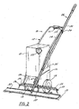
- FIGURE 2 is a view similar to FIGURE 1 showing the attachment of a mop
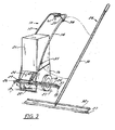
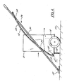
- FIGURE 4 is a side view of the applicator illustrated in FIGURE 1 with the mop attached and illustrating the dispensing of floor finish;
- FIGURE 5 is a detailed view showing the connection of the pivotal connecting spreader bar member
- FIGURE 6 is a front partial view showing the spreader bar member supporting the floor finish conveying conduits
- FIGURE 8 is a detailed view of the valve for controlling the flow of floor finish through the floor finish conveying conduits
- FIGURE 9 is a perspective view of the floor finish applicator embodying aspects of this invention, showing a mop disconnected from the applicator;
- FIGURE 10 is a side view of the applicator illustrated in FIGURE 9 with the mop attached and illustrating the actuation of a bail;
- FIGURE 11 is a detailed view of the stop mechanism for the bail illustrated in FIGURE 10 ;
- FIGURE 12 is a bottom view of the applicator shown in FIGURE 9 illustrating the drive means for activating a pump, the drive means in a deactivated position;
- FIGURE 13 is a detailed view of FIGURE 12 in cross-section showing a roller clutch in conjunction with a wheel;
- FIGURE 14 is a view similar to FIGURE 12 showing the drive means in an activated position
- FIGURE 15 is a sectional view taken along line 15-15 of FIGURE 14 ;
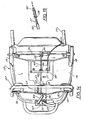
- FIGURE 16 is a front view of the applicator illustrated in FIGURE 9 showing the pump and illustrating the dispensing of floor finish.
- the floor finish applicator generally 10 includes a cart 12 with a U-shaped tubular handle member 14 joined to a base portion 16 with wheels 18 rotatably mounted thereon.
- a box 21 with a bag 23 containing floor finish is supported on base portion 16 which provides a carrier member for the box 21.
- a sloping panel 24 encloses the base portion 16.
- Cart 12 is supported by skid member 22.
- a spreader bar member 26 with a second spreader bar member 37 connected thereto.
- Spreader bar members 26 and 37 support floor finish conveying, flexible conduits 25 and 29 for depositing floor finish on floor surface 27.
- a mop generally 28 having a handle 30 and pad 32 is removably attached to the handle member 14 by the clamps 34 and 35.
- map pad 32 is comprised of materials of different sizes for purpose of spreading and leveling the floor finish. It can be made of foam, flocked foam, woven or non-woven cloth.
- spreader bar member 37 is pivotally connected to spreader bar member 26 by means of hinge 41. It is held in a hinged open position by bracket 43 and the pin 45. A second bracket 46 is connected to spreader bar member 26. This serves to clamp pivotal spreader bar 37 in a folded position as seen in FIGURE 7 when pin 45 is placed in bracket 46.
- Spreader bar members 26 and 37 have notches 39 for supporting conduits 25 and 29 therein.
- Feed tube 63 is connected to bag 23 and extends through pinch clamp 47 which includes body member 49 and clamp plate 51.
- Clamp member 53 is biased closed by spring 57 to position clamp member 53 in engagement with feed tube 63.
- FIGURE 7 Clamp member 53 is opened by the cable 59 connected to hinged clamp member 53 having support hinge 55.
- a control lever 61 on handle member 14 pulls cable 59 to open clamp member 53.
- Feed tube 63 is interconnected to conduits 25 and 29 by the Y connector 65.
- FIGURES 1-8 A further understanding of the floor finish applicator 10 can be had by a description of its operation as seen in FIGURES 1-8 .
- the bag 23 containing floor finish is placed in box 21 and the box loaded onto the cart 10 as illustrated in FIGURE 1 .
- Bag 23 is connected to feed tube 63 as indicated in FIGURE 6 which shows control clamp 47 in the closed position and pinching off the feed tube 63.
- pivotal spreader bar member 37 is in a folded position as illustrated in FIGURE 7 .
- pin 45 is pulled from bracket 46 and spreader bar member 37 pivotally extended to the position shown in FIGURE 6 by means of hinge 41. Pin 45 is then placed in bracket 43 to secure spreader bar 37 member to bar 26.
- Mop handle 30 is clamped to handle member 14 by means of clamps 34 and 35. It is positioned to extend in front of cart 12 and extended in a manner to lift skid member 22 so as to place a portion of the weight of the loaded cart 12 on the mop pad 32. This is seen in FIGURE 4 .
- This arrangement positions the cart about 5 degrees from an upright position.
- floor finish applicator 10 composed of consumable parts. This is seen though the use of the bag 23 in the box 21 as well as plastic feed tube 63 and conduits 25and 29. These parts are readily disposable after use. Further, floor finish applicator 10 provides a dual use of mop 28. It acts as a spreader for the floor finish when attached to the cart 12, yet allows use separately as a hand operated mop.
- a particular pinch valve 47 has been described in conjunction with applicator 10. Any type of clamp could be employed which effects a compressing and stoppage of flow through flexible tubing 63. Neither is the particular design of mop 28 essential. Any mop with a disposable mop head can be substituted as long as it effects appropriate spreading and leveling of the floor finish.
- FIGURES 1-8 relate to a floor finish applicator that delivered floor finish from a reservoir to the floor via gravitational forces. In other words, the assistance of a pump was not utilized.
- FIGURES 9-15 illustrate another floor finish applicator quite similar to the one illustrate above, except a pump is utilized to deliver the floor finish to the floor.
- Many features of this embodiment are quite similar to features of the embodiment illustrated in FIGURES 1-8 . As such, those common or similar features will generally be given similar reference numbers.
- the floor finish applicator generally 10 includes a cart 12 with a U-shaped tubular handle member 14 joined to a molded plastic base portion 16 with wheels 18 rotatably mounted thereon.
- a box 21 with a bag 23 containing floor finish is supported in housing 16 which provides a carrier member for the box 21.
- a kickstand 22 supports base portion 16 of cart 12.
- a spring 60 pivotally biases kickstand 22 toward the housing 16.
- mop head 32 has a pad comprised of materials of different sizes for purpose of spreading and leveling the floor finish. It can be made of foam, flocked foam, woven or non-woven cloth.
- the transmission assembly includes a spring loaded clutch 38 for selectively controlling actuation of the pump 64.
- the clutch includes a thrust washer 40 slideably received on drive shaft 42.
- a spring 44 biases washer 40 against pivotal bar 48.
- Cable 66 is attached to pivotal bar 48.
- a bevel gear 50 is connected to drive shaft 42.
- the opposing end of drive shaft 42 is slideably received in drive shaft 52 which connects to pump 64.
- a drive gear 54 is mounted on axle 56.
- cable 66 is also attached to bail 69 by the connecting peg 71 and is slideably secured in bracket 67 dispensed on handle 14.
- Bail 69 is pivotally attached to handle 14.
- the pump 64 can include a variety of different pumps, such as piston pump, gear pump, diaphragm pump, peristaltic pump, and the like. While each pump can be utilized to deliver floor finish and can be operable via the transmission assembly described above, the peristaltic pump embodiment is a highly preferred embodiment. As explained in greater detail below, the peristaltic pump is preferred because it is substantially easier to clean since the floor finish does not contact the pump.
- the peristaltic pump is housed in compartment 75.
- a floor finish feed conduit 25 is in fluid communication with the bag 23 by means of the connector 79.
- Feed conduit 25 is also in fluid communications with pump conduit 81 and is output conduit 83.
- Sleeves 85 provide connection between conduits 25, 83 and pump conduit 81.
- a spray conduit 87 with orifices 89 is attached to housing 16 by the brackets 90.
- FIGURES 9-16 A further understanding of the floor finish applicator 10 can be had by a description of its operation as seen in FIGURES 9-16 .
- the bag 23 containing floor finish in placed in box 21 and the box loaded into the housing 16 of cart 12 as illustrated in FIGURE 9 .
- Bag 23 is connected to flexible feed tube 25 as indicated in FIGURE 16 .
- Mop 28 is clamped to the applicator 10 by means of clamps 28 and 29, as shown in FIGURE 10 .
- the applicator 10 is moved in a direction indicated by the directional arrow 19 shown in FIGURE 10 .
- Bail 69 is then moved in the direction shown by the directional arrow 17, this causes pivotal bar 48 to move from the position shown in FIGURE 12 to that shown in FIGURE 14 whereby drive shaft 42 is moved by thrust washer 40 to move bevel gear 50 in engagement with drive gear 54 which is rotated by the rotation of axle 56 by wheels 18.
- Rotation of drive shaft 42 rotates drive shaft 52 through the pin 58 and slot 57 arrangement shown in FIGURE 15 . This affords linear movement of shaft 42 in shaft 52 while maintaining connection of the two shafts. Rotation of shaft 52 effects a pumping action in pump 64.
- peristaltic pump 64 As best seen in FIGURE 16 , floor finish flows through flexible feed conduit 25 into peristaltic pump 64. It is pumped into output flexible conduit 83 and into spray conduit 87 where it is dispensed through orifices 89. Activation of the peristaltic pump 64 during movement of the cart 12 can be prevented by the roller clutch 94 in conjunction with wheels 18. This is shown in FIGURE 13 .
- a roller bearing 92 is mounted on shaft 56 as is roller clutch 94.
- a spacer 93 separates bearing 92 and housing 16. In the event bail 69 is not moved to a position to place pivot bar 48 in the position shown in FIGURE 12 with the non-engagement of gears 50 and 54, roller clutch prevents activation of pump 64 during movement of the cart 12.
- An advantageous feature of some embodiments of the applicator is the disposable connector 79 and the disposable flexible conduits 25, 81, 83 and spray conduit 87.
- these components can be readily removed and replaced without any cleaning of the peristaltic pump 64.
- the floor finish never contacts the pump. As such, time consuming clean-up is not necessary. Rather, the conduit is simply removed from the pump and replaced prior to next operation.
- the application 10 is the dual use of mop 28. It acts as a spreader for the floor finish when attached to the cart 12, yet allows use separately as a hand operated mop in order to apply floor finish to areas of floors not readily accessible when attached to the applicator.
- a roller clutch 94 has been described in conjunction with applicator 10. If desired this could be eliminated as deactivation of the pump 64 can be effected during a forward motion of the applicator by placing bail 69 in the upward position shown in solid lines in FIGURE 10 . Neither is it essential to have the mop 28 disengageable from the applicator 10.
- the embodiment illustrated above harnessed the power of the wheels to drive the pump, other embodiments can utilize an electric pump with the detachable handle. All such and other modifications within the sprit of the invention are meant to be within the scope as defined by the appended claims. Further embodiments forming part of the present disclosure are set out in the numbered paragraphs below.
Landscapes
- Engineering & Computer Science (AREA)
- Mechanical Engineering (AREA)
- General Engineering & Computer Science (AREA)
- Cleaning Implements For Floors, Carpets, Furniture, Walls, And The Like (AREA)
- Handcart (AREA)
- Coating Apparatus (AREA)
- Cleaning By Liquid Or Steam (AREA)
Abstract
Description
- This is a continuation-in-part of
U.S. Serial No. 11/744,967, filed on May 7, 2007 - The present invention relates to applicators for floor finish. More particularly, it relates to a simplified pull-behind floor finish applicator which utilizes a pump and a detachable mop as a component of a pull-behind cart.
- Pull-behind floor finish applicators are disclosed in
U.S. Patents No. 2,979,756 ; No.3,457,015 ; No.3,981,596 ; No.4,124,315 ; and No.4,471,713 . Other floor finish applicators of this type are available from Fast-Trak Inc. as Ultra-Trak floor finish applicator and Hillyard, Inc. of St. Joseph, Missouri as Multi-Flo applicator. - These applicators involve mechanisms which have numerous components and/or do not provide for a separate mopping function. For example, the applicators described in
U.S. Patents No. 2,979,756 and No.3,981,596 include pressurized tanks with complex delivery systems. These involve time consuming cleaning operations. Those described inU.S. Patents No. 3,457,015 and No.4,124,315 do not provide for a separate mopping function. - A pull-behind floor finish applicator should be simple in its construction so as to be economical to produce. It should also be capable of applying floor finish in those places where the application cannot readily be achieved.
- The prior art does not provide a floor finish applicator which has a minimum number of parts, yet can apply floor finish in floor areas which are both readily accessible by a mobile machine and those which are not.
- One embodiment of the present invention provides a pull-behind floor finish applicator which includes a wheeled cart and receives a source of floor finish. A floor finish spreading mop having a handle member and a floor finnish spreading member is detachably mounted on the cart. In one embodiment, the floor finish spreading mop is detachably mounted to the cart by a clamp member. There is at least one conduit connected to the source of floor finish to deliver floor finish to a floor. In some embodiments, a valve member is operatively associated with the conduit, and a valve actuating member is operatively connected to the valve member. In some embodiments, the valve member is a pinch valve.
- In some embodiments there is a skid member connected to the cart, the mop positioned on the cart in a manner to position the cart at about 5 degrees from an upright position toward the front side of the cart.
- In some embodiments, there is a carrier member connected to the cart and a bag in the box containing a floor finish positioned in the carrier member. In some embodiments, the floor finish is delivered to the flow via gravity feed. In other embodiments, the floor finish is delivered via the assistance of a pump assembly. In some embodiments, the pump is a peristaltic pump.
- In some embodiments, the pump assembly is driven by a power delivered via rotation of the wheel on the cart.
- Some embodiments of the invention are directed toward a transmission assembly for selectively driving a pump on a floor finish applicator cart having wheels. The transmission assembly comprises an axle coupled to and driven by a wheel on the cart, a drive gear connected to the axle; and a drive shaft with a bevel gear for engaging the drive gear and driving the pump. In some embodiments, the drive gear includes a one-way roller clutch. In some embodiments, the transmission assembly also includes a spring loaded clutch actuator, wherein the spring loaded clutch actuator includes at least one thrust washer and a pivotal bar member for engaging the thrust washer.
- Some embodiments are also directed toward a floor finish applicator having a body member adapted to support a reservoir of floor finish, a handle coupled to the body, a pair of wheels coupled to the body member and at least partially defining a pivot point of the body when force is applied to the handle, and a kick-stand pivotally coupled to the body and engagable with the floor to support the body in a raised position relative to the floor, wherein the kick-stand is biased about a pivot point toward the body when not engaged with the floor.
-
FIGURE 1 is a perspective view of the floor finish applicator illustrating the placement of a box containing floor finish thereon; -
FIGURE 2 is a view similar toFIGURE 1 showing the attachment of a mop; -
FIGURE 3 is a view similar toFIGURE 2 showing the mop disconnected from the applicator; -
FIGURE 4 is a side view of the applicator illustrated inFIGURE 1 with the mop attached and illustrating the dispensing of floor finish; -
FIGURE 5 is a detailed view showing the connection of the pivotal connecting spreader bar member; -
FIGURE 6 is a front partial view showing the spreader bar member supporting the floor finish conveying conduits; -
FIGURE 7 is a view similar toFIGURE 6 illustrating the spreader bar members in a folded condition; -
FIGURE 8 is a detailed view of the valve for controlling the flow of floor finish through the floor finish conveying conduits; -
FIGURE 9 is a perspective view of the floor finish applicator embodying aspects of this invention, showing a mop disconnected from the applicator; -
FIGURE 10 is a side view of the applicator illustrated inFIGURE 9 with the mop attached and illustrating the actuation of a bail; -
FIGURE 11 is a detailed view of the stop mechanism for the bail illustrated inFIGURE 10 ; -
FIGURE 12 is a bottom view of the applicator shown inFIGURE 9 illustrating the drive means for activating a pump, the drive means in a deactivated position; -
FIGURE 13 is a detailed view ofFIGURE 12 in cross-section showing a roller clutch in conjunction with a wheel; -
FIGURE 14 is a view similar toFIGURE 12 showing the drive means in an activated position; -
FIGURE 15 is a sectional view taken along line 15-15 ofFIGURE 14 ; and -
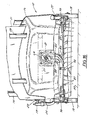
FIGURE 16 is a front view of the applicator illustrated inFIGURE 9 showing the pump and illustrating the dispensing of floor finish. - Referring to
FIGURES 1-3 , the floor finish applicator generally 10 includes acart 12 with a U-shapedtubular handle member 14 joined to abase portion 16 withwheels 18 rotatably mounted thereon. A box 21 with a bag 23 containing floor finish is supported onbase portion 16 which provides a carrier member for the box 21. Asloping panel 24 encloses thebase portion 16.Cart 12 is supported by skidmember 22. Also connected to thehandle member 14 is a spreader bar member 26 with a second spreader bar member 37 connected thereto. Spreader bar members 26 and 37 support floor finish conveying,flexible conduits 25 and 29 for depositing floor finish on floor surface 27. A mop generally 28 having ahandle 30 andpad 32 is removably attached to thehandle member 14 by theclamps map pad 32 is comprised of materials of different sizes for purpose of spreading and leveling the floor finish. It can be made of foam, flocked foam, woven or non-woven cloth. - Referring to
FIGURES 5-7 , spreader bar member 37 is pivotally connected to spreader bar member 26 by means of hinge 41. It is held in a hinged open position by bracket 43 and the pin 45. A second bracket 46 is connected to spreader bar member 26. This serves to clamp pivotal spreader bar 37 in a folded position as seen inFIGURE 7 when pin 45 is placed in bracket 46. Spreader bar members 26 and 37 have notches 39 for supportingconduits 25 and 29 therein. - The flow of floor finnish from bag 23 to
conduits 25 and 29 is controlled by the control pinch clamp generally 47 connected to slopingpanel 24. This is best seen inFIGURE 8 .Feed tube 63 is connected to bag 23 and extends through pinch clamp 47 which includesbody member 49 and clamp plate 51.Clamp member 53 is biased closed by spring 57 to positionclamp member 53 in engagement withfeed tube 63. This is seen inFIGURE 7 .Clamp member 53 is opened by thecable 59 connected to hingedclamp member 53 having support hinge 55. A control lever 61 onhandle member 14 pullscable 59 to openclamp member 53.Feed tube 63 is interconnected toconduits 25 and 29 by theY connector 65. - A further understanding of the
floor finish applicator 10 can be had by a description of its operation as seen inFIGURES 1-8 . The bag 23 containing floor finish is placed in box 21 and the box loaded onto thecart 10 as illustrated inFIGURE 1 . Bag 23 is connected to feedtube 63 as indicated inFIGURE 6 which shows control clamp 47 in the closed position and pinching off thefeed tube 63. Initially, pivotal spreader bar member 37 is in a folded position as illustrated inFIGURE 7 . To extend bar 37, pin 45 is pulled from bracket 46 and spreader bar member 37 pivotally extended to the position shown inFIGURE 6 by means of hinge 41. Pin 45 is then placed in bracket 43 to secure spreader bar 37 member to bar 26. This provides an offset position from a central axis of thecart 12 and places the open ends of 31 and 33 ofconduits 29 and 25, respectively in a dispensing position. The open ends 31 and 33 have dispensing nozzles such as nozzle 36 attached thereto as seen inFIGURE 4 . Mop handle 30 is clamped to handlemember 14 by means ofclamps cart 12 and extended in a manner to liftskid member 22 so as to place a portion of the weight of the loadedcart 12 on themop pad 32. This is seen inFIGURE 4 . This arrangement positions the cart about 5 degrees from an upright position. - Pinch valve 47 is opened by compressing lever 61 which places the pinch clamp 47 in the position seen in
FIGURE 8 . Floor finish then flows throughconduits 25 and 29 and out through nozzles such as 36. Floor finish is distributed by themop pad 32 as thecart 12 is moved in a backward manner. In order to apply floor finish to a surface not easily accessible by thecart 12, themop 28 is unclamped therefrom and employed in the usual manner. - It will thus be seen that there is provided a floor finish applicator composed of consumable parts. This is seen though the use of the bag 23 in the box 21 as well as
plastic feed tube 63 and conduits 25and 29. These parts are readily disposable after use. Further,floor finish applicator 10 provides a dual use ofmop 28. It acts as a spreader for the floor finish when attached to thecart 12, yet allows use separately as a hand operated mop. - A particular pinch valve 47 has been described in conjunction with
applicator 10. Any type of clamp could be employed which effects a compressing and stoppage of flow throughflexible tubing 63. Neither is the particular design ofmop 28 essential. Any mop with a disposable mop head can be substituted as long as it effects appropriate spreading and leveling of the floor finish. - The embodiment illustrated in
FIGURES 1-8 related to a floor finish applicator that delivered floor finish from a reservoir to the floor via gravitational forces. In other words, the assistance of a pump was not utilized.FIGURES 9-15 , however, illustrate another floor finish applicator quite similar to the one illustrate above, except a pump is utilized to deliver the floor finish to the floor. Many features of this embodiment are quite similar to features of the embodiment illustrated inFIGURES 1-8 . As such, those common or similar features will generally be given similar reference numbers. - As shown in
FIGURES 9-10 , the floor finish applicator generally 10 includes acart 12 with a U-shapedtubular handle member 14 joined to a moldedplastic base portion 16 withwheels 18 rotatably mounted thereon. A box 21 with a bag 23 containing floor finish is supported inhousing 16 which provides a carrier member for the box 21. Akickstand 22supports base portion 16 ofcart 12. Aspring 60 pivotally biases kickstand 22 toward thehousing 16. - Connected to the
housing 16 is aframe member 20 withclamps mop 28 having ahandle 30 and amop head 32 is removably attached to theframe member 20 by theclamps mop head 32 has a pad comprised of materials of different sizes for purpose of spreading and leveling the floor finish. It can be made of foam, flocked foam, woven or non-woven cloth. - Referring to
FIGURES 11 ,14 & 15 a transmission assembly for transmitting power from the wheels to the pump 64 is shown. The transmission assembly includes a spring loaded clutch 38 for selectively controlling actuation of the pump 64. The clutch includes a thrust washer 40 slideably received on drive shaft 42. A spring 44 biases washer 40 againstpivotal bar 48.Cable 66 is attached topivotal bar 48. A bevel gear 50 is connected to drive shaft 42. The opposing end of drive shaft 42 is slideably received in drive shaft 52 which connects to pump 64. A drive gear 54 is mounted on axle 56. - As seen in
FIGURES 10 and13 ,cable 66 is also attached to bail 69 by the connecting peg 71 and is slideably secured inbracket 67 dispensed onhandle 14.Bail 69 is pivotally attached to handle 14. There is also abail stop 73 connected to handle 14. - The pump 64 can include a variety of different pumps, such as piston pump, gear pump, diaphragm pump, peristaltic pump, and the like. While each pump can be utilized to deliver floor finish and can be operable via the transmission assembly described above, the peristaltic pump embodiment is a highly preferred embodiment. As explained in greater detail below, the peristaltic pump is preferred because it is substantially easier to clean since the floor finish does not contact the pump.
- Referring to
FIGURE 16 , the peristaltic pump is housed incompartment 75. A floorfinish feed conduit 25 is in fluid communication with the bag 23 by means of the connector 79. Feedconduit 25 is also in fluid communications withpump conduit 81 and isoutput conduit 83.Sleeves 85 provide connection betweenconduits pump conduit 81. Aspray conduit 87 with orifices 89 is attached tohousing 16 by thebrackets 90. - A further understanding of the
floor finish applicator 10 can be had by a description of its operation as seen inFIGURES 9-16 . The bag 23 containing floor finish in placed in box 21 and the box loaded into thehousing 16 ofcart 12 as illustrated inFIGURE 9 . Bag 23 is connected toflexible feed tube 25 as indicated inFIGURE 16 .Mop 28 is clamped to theapplicator 10 by means ofclamps 28 and 29, as shown inFIGURE 10 . When it is desired to dispense floor finish from bag 23 onto the floor surface 27, theapplicator 10 is moved in a direction indicated by the directional arrow 19 shown inFIGURE 10 .Bail 69 is then moved in the direction shown by the directional arrow 17, this causespivotal bar 48 to move from the position shown inFIGURE 12 to that shown inFIGURE 14 whereby drive shaft 42 is moved by thrust washer 40 to move bevel gear 50 in engagement with drive gear 54 which is rotated by the rotation of axle 56 bywheels 18. Rotation of drive shaft 42 rotates drive shaft 52 through the pin 58 and slot 57 arrangement shown inFIGURE 15 . This affords linear movement of shaft 42 in shaft 52 while maintaining connection of the two shafts. Rotation of shaft 52 effects a pumping action in pump 64. - As best seen in
FIGURE 16 , floor finish flows throughflexible feed conduit 25 into peristaltic pump 64. It is pumped into outputflexible conduit 83 and intospray conduit 87 where it is dispensed through orifices 89. Activation of the peristaltic pump 64 during movement of thecart 12 can be prevented by the roller clutch 94 in conjunction withwheels 18. This is shown inFIGURE 13 . A roller bearing 92 is mounted on shaft 56 as is roller clutch 94. A spacer 93 separates bearing 92 andhousing 16. In theevent bail 69 is not moved to a position to placepivot bar 48 in the position shown inFIGURE 12 with the non-engagement of gears 50 and 54, roller clutch prevents activation of pump 64 during movement of thecart 12. - An advantageous feature of some embodiments of the applicator is the disposable connector 79 and the disposable
flexible conduits spray conduit 87. When the application of the floor finish in complete, these components can be readily removed and replaced without any cleaning of the peristaltic pump 64. In other words, through the use of a peristaltic pump, the floor finish never contacts the pump. As such, time consuming clean-up is not necessary. Rather, the conduit is simply removed from the pump and replaced prior to next operation. - Another advantage of some embodiments the
application 10 is the dual use ofmop 28. It acts as a spreader for the floor finish when attached to thecart 12, yet allows use separately as a hand operated mop in order to apply floor finish to areas of floors not readily accessible when attached to the applicator. - A roller clutch 94 has been described in conjunction with
applicator 10. If desired this could be eliminated as deactivation of the pump 64 can be effected during a forward motion of the applicator by placingbail 69 in the upward position shown in solid lines inFIGURE 10 . Neither is it essential to have themop 28 disengageable from theapplicator 10. Furthermore, although the embodiment illustrated above harnessed the power of the wheels to drive the pump, other embodiments can utilize an electric pump with the detachable handle. All such and other modifications within the sprit of the invention are meant to be within the scope as defined by the appended claims.
Further embodiments forming part of the present disclosure are set out in the numbered paragraphs below. - Paragraph 1. A floor finish applicator comprising:
- a cart having wheels and a body member constructed and arranged to receive a source of floor finish; and
- a floor finish spreading mop having a handle member and a floor finish spreading member detachably mounted on the cart for selective use detached from the cart during use of the cart.
-
Paragraph 2. The floor finish applicator of paragraph 1, further comprising a pump coupled to the cart and operable to deliver floor finish to a floor. - Paragraph 3. The floor finish applicator of
paragraph 2, wherein the pump is a peristaltic pump. - Paragraph 4. The floor finish applicator of
paragraph 2, further comprising a conduit adapted to be coupled to the source of floor finish and deliver floor finish to the pump. - Paragraph 5. The floor finish applicator of
paragraph 2, further comprising a transmission assembly coupled between the pump and the wheels and selectively operable via movement of the wheels to drive the pump. - Paragraph 6. The floor finish applicator of paragraph 5, further comprising control means operatively associated with the transmission assembly to selectively control the operation of the pump.
- Paragraph 7. The floor finish applicator of paragraph 6, wherein the control means includes a spring loaded clutch actuator.
-
Paragraph 8. The floor finish applicator of paragraph 7, wherein the spring loaded clutch actuator includes at least one thrust washer and a pivotal bar member for engaging the thrust washer. - Paragraph 9. The floor finish applicator of paragraph 5, wherein the transmission assembly includes a drive gear connected to a wheel driven axle and a drive shaft with a bevel gear for engaging the drive gear and driving the pump.
-
Paragraph 10. The floor finish applicator of paragraph 9, wherein the drive gear includes a one-way roller clutch. - Paragraph 11. The floor finish applicator of paragraph 9, wherein the drive shaft includes a first shaft with the bevel gear and a second shaft, the shafts interconnected by a pin and slot arrangement.
-
Paragraph 12. The floor finish applicator of paragraph 1, wherein the wheeled cart includes a clamp member to selectively receive a handle of a mop with the mop head engaged with the floor. - Paragraph 13. The floor finish applicator of paragraph 6, wherein the control means includes a lever attached to the drive shaft, a cable attached to the drive shaft and handle member to actuate the cable.
-
Paragraph 14. A method of applying floor finish to a floor surface employing the applicator of paragraph 1. - Paragraph 15. A transmission assembly for selectively driving a pump on a floor finish applicator cart having wheels, the transmission assembly comprising:
- an axle coupled to and driven by a wheel on the cart,
- a drive gear connected to the axle; and
- a drive shaft with a bevel gear for engaging the drive gear and driving the pump.
-
Paragraph 16. The transmission assembly of paragraph 15, wherein the drive gear includes a one-way roller clutch. - Paragraph 17. The transmission assembly of
paragraph 16, further comprising a spring loaded clutch actuator. -
Paragraph 18. The transmission assembly of paragraph 17, wherein the spring loaded clutch actuator includes at least one thrust washer and a pivotal bar member for engaging the thrust washer. - Paragraph 19. The transmission assembly of paragraph 15, wherein the drive shaft includes a first shaft with the bevel gear and a second shaft, the shafts interconnected by a pin and slot arrangement.
-
Paragraph 20, A floor finish applicator comprising:- a body member adapted to support a reservoir of floor finish;
- a handle coupled to the body;
- a pair of wheels coupled to the body member and at least partially defining a pivot point of the body when force is applied to the handle; and
- a kick-stand pivotally coupled to the body and engagable with the floor to support the body in a raised position relative to the floor, wherein the kick-stand is biased about a pivot point toward the body when not engaged with the floor.
Claims (5)
- A transmission assembly (38, 40, 42, 44, 48, 50, 52, 54, 56) for selectively driving a pump (64) on a floor finish applicator cart (12) having wheels (18), the transmission assembly comprising:an axle (56) coupled to and driven by a wheel (18) on the cart,a drive gear (54) connected to the axle; anda drive shaft (42) with a bevel gear (50) for engaging the drive gear anddriving the pump.
- The transmission assembly of claim 1, wherein the drive gear (54) includes a one-way roller clutch.
- The transmission assembly of claim 2, further comprising a spring loaded clutch actuator (38).
- The transmission assembly of claim 3, wherein the spring loaded clutch actuator (39) includes at least one thrust washer (40) and a pivotal bar member (48) for engaging the thrust washer.
- The transmission assembly of claim 1, wherein the drive shaft (42) includes a first shaft with the bevel gear (50) and a second shaft, the shafts interconnected by a pin and slot arrangement (57,58).
Applications Claiming Priority (3)
| Application Number | Priority Date | Filing Date | Title |
|---|---|---|---|
| US11/744,967 US7850383B2 (en) | 2007-05-07 | 2007-05-07 | Floor finish applicator |
| US11/780,733 US20080279610A1 (en) | 2007-05-07 | 2007-07-20 | Floor finish applicator |
| EP08747044.9A EP2142068B1 (en) | 2007-05-07 | 2008-04-28 | Floor finish applicator |
Related Parent Applications (3)
| Application Number | Title | Priority Date | Filing Date |
|---|---|---|---|
| EP08747044.9A Division-Into EP2142068B1 (en) | 2007-05-07 | 2008-04-28 | Floor finish applicator |
| EP08747044.9A Division EP2142068B1 (en) | 2007-05-07 | 2008-04-28 | Floor finish applicator |
| EP08747044.9 Division | 2008-04-28 |
Publications (2)
| Publication Number | Publication Date |
|---|---|
| EP2508112A1 true EP2508112A1 (en) | 2012-10-10 |
| EP2508112B1 EP2508112B1 (en) | 2013-11-27 |
Family
ID=39943895
Family Applications (2)
| Application Number | Title | Priority Date | Filing Date |
|---|---|---|---|
| EP12174935.2A Not-in-force EP2508112B1 (en) | 2007-05-07 | 2008-04-28 | Floor finish applicator |
| EP08747044.9A Not-in-force EP2142068B1 (en) | 2007-05-07 | 2008-04-28 | Floor finish applicator |
Family Applications After (1)
| Application Number | Title | Priority Date | Filing Date |
|---|---|---|---|
| EP08747044.9A Not-in-force EP2142068B1 (en) | 2007-05-07 | 2008-04-28 | Floor finish applicator |
Country Status (9)
| Country | Link |
|---|---|
| US (3) | US20080279610A1 (en) |
| EP (2) | EP2508112B1 (en) |
| JP (2) | JP5572545B2 (en) |
| KR (1) | KR101433416B1 (en) |
| CN (1) | CN101686786B (en) |
| AU (1) | AU2008247827A1 (en) |
| BR (1) | BRPI0811495A8 (en) |
| CA (1) | CA2685532C (en) |
| WO (1) | WO2008137391A1 (en) |
Families Citing this family (16)
| Publication number | Priority date | Publication date | Assignee | Title |
|---|---|---|---|---|
| US20080279610A1 (en) * | 2007-05-07 | 2008-11-13 | Bober Andrew M | Floor finish applicator |
| US8246263B2 (en) | 2007-07-20 | 2012-08-21 | Diversey, Inc. | Floor finish applicator |
| JP2012512006A (en) | 2008-12-16 | 2012-05-31 | ディバーシー・インコーポレーテッド | Floor finish applicator |
| CN102379661B (en) * | 2011-10-18 | 2013-07-17 | 苏州爱普电器有限公司 | Steam cleaning equipment |
| US10407591B2 (en) | 2014-12-02 | 2019-09-10 | Ecolab Usa Inc. | Low solids surface coating compositions and use thereof |
| KR200479513Y1 (en) * | 2015-10-22 | 2016-02-04 | 김기훈 | sweeping device |
| US20190072085A1 (en) * | 2017-09-06 | 2019-03-07 | Allan Schultz | Portable solar powered fluid dispenser for release agents |
| JP6950946B2 (en) * | 2017-10-27 | 2021-10-13 | オート化学工業株式会社 | Coating device |
| CN107984911A (en) * | 2017-11-24 | 2018-05-04 | 福州皇家地坪有限公司 | Terrace printing monochromatic spraying stamp double-purpose machine and its method of work |
| WO2019125953A1 (en) | 2017-12-21 | 2019-06-27 | Tti (Macao Commercial Offshore) Limited | Support structure for a surface cleaning device |
| CN111067437A (en) * | 2018-10-22 | 2020-04-28 | 东北林业大学 | A household modular cleaning robot |
| US11564815B2 (en) | 2019-09-17 | 2023-01-31 | Victoria Hand Project | Upper arm prosthetic apparatus and systems |
| CN111364740A (en) * | 2020-04-10 | 2020-07-03 | 扬州光迈五金工具材料有限公司 | Novel slurry-pushing mop machine |
| CN114482477B (en) * | 2022-03-31 | 2023-09-19 | 安徽开盛津城建设有限公司 | Waterproof table plastering device |
| KR102863765B1 (en) | 2023-10-25 | 2025-09-24 | 주식회사 크리트건설 | Height adjustment device for flooring material for application |
| CN119062545B (en) * | 2024-11-04 | 2025-04-08 | 盐城市建龙机电设备制造有限公司 | Adjustable gasoline-driven air compressor |
Citations (7)
| Publication number | Priority date | Publication date | Assignee | Title |
|---|---|---|---|---|
| US2979756A (en) | 1959-10-08 | 1961-04-18 | George H Wallis | Wax spreader |
| US3457015A (en) | 1967-09-18 | 1969-07-22 | James A Taber | Mobile wax applicator |
| DE2411486A1 (en) * | 1974-03-11 | 1975-09-25 | Leifheit International | Carpet sweeper with independently operated corner brushes - has epicyclic gearing allowing drive energy to be stored for subsequent use |
| US3981596A (en) | 1974-01-09 | 1976-09-21 | Melton Systems, Inc. | Floor finish applicator |
| US4471713A (en) | 1983-03-21 | 1984-09-18 | Kenneth J. Cote | Floor treating apparatus |
| DE4211789A1 (en) * | 1992-04-08 | 1993-10-14 | Kaercher Gmbh & Co Alfred | Mechanical road sweeper driven by wheel rolling over surface to be swept - has height adjustable disc brush and bevel gear on common shaft, gear rotating brush by being lowered onto second bevelled gear |
| US6524386B1 (en) * | 2002-02-20 | 2003-02-25 | David P. Slager, Sr. | Surface treating apparatus |
Family Cites Families (33)
| Publication number | Priority date | Publication date | Assignee | Title |
|---|---|---|---|---|
| US1538226A (en) * | 1923-01-31 | 1925-05-19 | James M Davis | Suction sweeper |
| US1516734A (en) * | 1923-11-26 | 1924-11-25 | Radio Vacuum Cleaner Company | Clutch |
| US1786067A (en) * | 1928-04-30 | 1930-12-23 | Detroit Harvester Co | Driving attachment for tractors |
| US2104387A (en) * | 1935-01-31 | 1938-01-04 | Gen Motors Corp | Refrigerating apparatus |
| US2737340A (en) * | 1952-12-01 | 1956-03-06 | Robert A Bonini | Spraying attachment for lawn mower |
| US3174604A (en) * | 1961-12-14 | 1965-03-23 | Allis Chalmers Mfg Co | Clutch lever arrangement for control of ground driven pump |
| US3470767A (en) * | 1968-03-19 | 1969-10-07 | Billy C Gray | Oil transfer pump for vehicles |
| JPS5215057Y1 (en) * | 1970-01-28 | 1977-04-05 | ||
| US4002560A (en) * | 1975-07-24 | 1977-01-11 | Grantham Frederick W | Automatic article sorting apparatus |
| US4296875A (en) | 1979-11-29 | 1981-10-27 | Richway Industries Ltd. | Foam dispensing apparatus for marking on a ground surface the working pattern of a surface working vehicle |
| US4588318A (en) * | 1980-12-22 | 1986-05-13 | Black & Decker Inc. | Painting applicator with remote transmitter control |
| US4475872A (en) * | 1982-09-28 | 1984-10-09 | Robbins & Myers, Inc. | Water pump and gear box therefor |
| JPS6371101A (en) | 1986-09-12 | 1988-03-31 | 井関農機株式会社 | Working machine transmission gear made of sheet metal in walking type moving agricultural machine |
| JP2928356B2 (en) | 1990-08-28 | 1999-08-03 | 富士通株式会社 | Moving image area dividing device |
| JP3124347B2 (en) | 1991-07-17 | 2001-01-15 | 東燃株式会社 | Method for producing .GAMMA.-butyrolactone |
| CN2118022U (en) * | 1991-10-26 | 1992-10-07 | 张东赋 | Portable hand cart or travelling |
| US5433380A (en) | 1994-02-02 | 1995-07-18 | Hahn, Inc. | Self-cleansing pressure washing system for chemical sprayer |
| US5657503A (en) * | 1995-06-07 | 1997-08-19 | Caruso; Steven Jerome | Automated rotary mopping, waxing, and light sweeping systems |
| JPH1140521A (en) * | 1997-05-20 | 1999-02-12 | Seiko Instr Inc | Manufacturing method of semiconductor chip |
| JP3558846B2 (en) | 1997-11-28 | 2004-08-25 | アマノ株式会社 | Floor polisher with dust collection function |
| US6017163A (en) * | 1998-02-11 | 2000-01-25 | Ecolab, Inc. | Floor finish distribution apparatus |
| US6154917A (en) | 1999-01-08 | 2000-12-05 | Royal Appliance Mfg. Co. | Carpet extractor housing |
| JP4106673B2 (en) | 1999-03-05 | 2008-06-25 | 株式会社エフ・イー・シー | Antenna device using coil unit, printed circuit board |
| US6827237B2 (en) * | 2000-04-13 | 2004-12-07 | Dr Pepper/Seven-Up, Inc. | Bag-in-box container for liquids |
| US7137170B1 (en) * | 2002-02-01 | 2006-11-21 | Nss Enterprises, Inc. | Manual scrubber with vacuum pick-up |
| US6875497B2 (en) | 2002-05-08 | 2005-04-05 | Flexcon Company, Inc. | Multilayer composite for the dry transfer of graphics to receptive substrates |
| US20050254879A1 (en) | 2002-06-13 | 2005-11-17 | Gundersen Robert J | Adjustable flow texture sprayer with peristaltic pump |
| US6854912B2 (en) * | 2003-06-04 | 2005-02-15 | 3M Innovative Properties Company | Mop assembly and cart |
| CN2689880Y (en) * | 2003-10-23 | 2005-04-06 | 陈振平 | Floor mopping machine |
| JP2006212279A (en) | 2005-02-04 | 2006-08-17 | Toshiba Tec Corp | Squeegee and vacuum cleaner with this squeegee |
| US20080104783A1 (en) | 2006-10-04 | 2008-05-08 | Scott Crawford | Dust mop |
| US20080279610A1 (en) * | 2007-05-07 | 2008-11-13 | Bober Andrew M | Floor finish applicator |
| US7850383B2 (en) * | 2007-05-07 | 2010-12-14 | Diversey, Inc. | Floor finish applicator |
-
2007
- 2007-07-20 US US11/780,733 patent/US20080279610A1/en not_active Abandoned
-
2008
- 2008-04-28 JP JP2010507524A patent/JP5572545B2/en not_active Expired - Fee Related
- 2008-04-28 WO PCT/US2008/061803 patent/WO2008137391A1/en not_active Ceased
- 2008-04-28 AU AU2008247827A patent/AU2008247827A1/en not_active Abandoned
- 2008-04-28 CN CN2008800149273A patent/CN101686786B/en not_active Expired - Fee Related
- 2008-04-28 EP EP12174935.2A patent/EP2508112B1/en not_active Not-in-force
- 2008-04-28 CA CA2685532A patent/CA2685532C/en active Active
- 2008-04-28 KR KR1020097025366A patent/KR101433416B1/en not_active Expired - Fee Related
- 2008-04-28 BR BRPI0811495A patent/BRPI0811495A8/en not_active IP Right Cessation
- 2008-04-28 EP EP08747044.9A patent/EP2142068B1/en not_active Not-in-force
-
2011
- 2011-06-10 US US13/157,582 patent/US8366336B2/en active Active
-
2013
- 2013-02-05 US US13/759,595 patent/US8608396B2/en not_active Expired - Fee Related
-
2014
- 2014-06-27 JP JP2014132626A patent/JP2014196661A/en active Pending
Patent Citations (8)
| Publication number | Priority date | Publication date | Assignee | Title |
|---|---|---|---|---|
| US2979756A (en) | 1959-10-08 | 1961-04-18 | George H Wallis | Wax spreader |
| US3457015A (en) | 1967-09-18 | 1969-07-22 | James A Taber | Mobile wax applicator |
| US3981596A (en) | 1974-01-09 | 1976-09-21 | Melton Systems, Inc. | Floor finish applicator |
| US4124315A (en) | 1974-01-09 | 1978-11-07 | Melton Systems, Inc. | Floor finish applicator |
| DE2411486A1 (en) * | 1974-03-11 | 1975-09-25 | Leifheit International | Carpet sweeper with independently operated corner brushes - has epicyclic gearing allowing drive energy to be stored for subsequent use |
| US4471713A (en) | 1983-03-21 | 1984-09-18 | Kenneth J. Cote | Floor treating apparatus |
| DE4211789A1 (en) * | 1992-04-08 | 1993-10-14 | Kaercher Gmbh & Co Alfred | Mechanical road sweeper driven by wheel rolling over surface to be swept - has height adjustable disc brush and bevel gear on common shaft, gear rotating brush by being lowered onto second bevelled gear |
| US6524386B1 (en) * | 2002-02-20 | 2003-02-25 | David P. Slager, Sr. | Surface treating apparatus |
Also Published As
| Publication number | Publication date |
|---|---|
| EP2142068A4 (en) | 2012-03-28 |
| JP2014196661A (en) | 2014-10-16 |
| US20080279610A1 (en) | 2008-11-13 |
| US8366336B2 (en) | 2013-02-05 |
| CA2685532C (en) | 2014-11-18 |
| CN101686786A (en) | 2010-03-31 |
| CN101686786B (en) | 2012-05-09 |
| EP2142068B1 (en) | 2014-08-13 |
| JP5572545B2 (en) | 2014-08-13 |
| KR101433416B1 (en) | 2014-08-26 |
| US20130149020A1 (en) | 2013-06-13 |
| US8608396B2 (en) | 2013-12-17 |
| WO2008137391A1 (en) | 2008-11-13 |
| JP2010526952A (en) | 2010-08-05 |
| BRPI0811495A2 (en) | 2014-11-18 |
| BRPI0811495A8 (en) | 2017-03-01 |
| CA2685532A1 (en) | 2008-11-13 |
| EP2508112B1 (en) | 2013-11-27 |
| KR20100017628A (en) | 2010-02-16 |
| EP2142068A1 (en) | 2010-01-13 |
| US20110262205A1 (en) | 2011-10-27 |
| AU2008247827A1 (en) | 2008-11-13 |
Similar Documents
| Publication | Publication Date | Title |
|---|---|---|
| EP2142068B1 (en) | Floor finish applicator | |
| AU2008279362B2 (en) | Floor finish applicator | |
| US8109685B1 (en) | Liquid dispenser with interchangeable head and remote operating mechanism | |
| US7850383B2 (en) | Floor finish applicator | |
| US20090178228A1 (en) | Floor-cleaning machine | |
| AU2009333263A1 (en) | Floor finish applicator | |
| WO2006053079A1 (en) | Dispenser carrier assembly | |
| JP2016202512A (en) | wheelchair | |
| US20090178227A1 (en) | Floor-cleaning machine | |
| US6524386B1 (en) | Surface treating apparatus | |
| WO2007134044A2 (en) | Fluid applicator assembly | |
| JPH0563227B2 (en) | ||
| JPH06330619A (en) | Movable working platform | |
| JP3921312B2 (en) | Liquid spraying device |
Legal Events
| Date | Code | Title | Description |
|---|---|---|---|
| PUAI | Public reference made under article 153(3) epc to a published international application that has entered the european phase |
Free format text: ORIGINAL CODE: 0009012 |
|
| AC | Divisional application: reference to earlier application |
Ref document number: 2142068 Country of ref document: EP Kind code of ref document: P |
|
| AK | Designated contracting states |
Kind code of ref document: A1 Designated state(s): AT BE BG CH CY CZ DE DK EE ES FI FR GB GR HR HU IE IS IT LI LT LU LV MC MT NL NO PL PT RO SE SI SK TR |
|
| 17P | Request for examination filed |
Effective date: 20130218 |
|
| GRAP | Despatch of communication of intention to grant a patent |
Free format text: ORIGINAL CODE: EPIDOSNIGR1 |
|
| RIC1 | Information provided on ipc code assigned before grant |
Ipc: A47L 13/26 20060101AFI20130513BHEP Ipc: A47L 11/03 20060101ALI20130513BHEP Ipc: A47L 13/256 20060101ALN20130513BHEP Ipc: A47L 13/22 20060101ALI20130513BHEP Ipc: A47L 11/40 20060101ALI20130513BHEP Ipc: A47L 13/00 20060101ALI20130513BHEP Ipc: A47L 11/04 20060101ALN20130513BHEP Ipc: A47L 13/31 20060101ALN20130513BHEP |
|
| INTG | Intention to grant announced |
Effective date: 20130613 |
|
| GRAS | Grant fee paid |
Free format text: ORIGINAL CODE: EPIDOSNIGR3 |
|
| GRAA | (expected) grant |
Free format text: ORIGINAL CODE: 0009210 |
|
| AC | Divisional application: reference to earlier application |
Ref document number: 2142068 Country of ref document: EP Kind code of ref document: P |
|
| AK | Designated contracting states |
Kind code of ref document: B1 Designated state(s): AT BE BG CH CY CZ DE DK EE ES FI FR GB GR HR HU IE IS IT LI LT LU LV MC MT NL NO PL PT RO SE SI SK TR |
|
| REG | Reference to a national code |
Ref country code: GB Ref legal event code: FG4D |
|
| REG | Reference to a national code |
Ref country code: CH Ref legal event code: NV Representative=s name: E. BLUM AND CO. AG PATENT- UND MARKENANWAELTE , CH Ref country code: CH Ref legal event code: EP |
|
| REG | Reference to a national code |
Ref country code: AT Ref legal event code: REF Ref document number: 642328 Country of ref document: AT Kind code of ref document: T Effective date: 20131215 |
|
| REG | Reference to a national code |
Ref country code: IE Ref legal event code: FG4D |
|
| REG | Reference to a national code |
Ref country code: DE Ref legal event code: R096 Ref document number: 602008029050 Country of ref document: DE Effective date: 20140123 |
|
| REG | Reference to a national code |
Ref country code: NL Ref legal event code: VDEP Effective date: 20131127 |
|
| REG | Reference to a national code |
Ref country code: AT Ref legal event code: MK05 Ref document number: 642328 Country of ref document: AT Kind code of ref document: T Effective date: 20131127 |
|
| REG | Reference to a national code |
Ref country code: LT Ref legal event code: MG4D |
|
| PG25 | Lapsed in a contracting state [announced via postgrant information from national office to epo] |
Ref country code: FI Free format text: LAPSE BECAUSE OF FAILURE TO SUBMIT A TRANSLATION OF THE DESCRIPTION OR TO PAY THE FEE WITHIN THE PRESCRIBED TIME-LIMIT Effective date: 20131127 Ref country code: HR Free format text: LAPSE BECAUSE OF FAILURE TO SUBMIT A TRANSLATION OF THE DESCRIPTION OR TO PAY THE FEE WITHIN THE PRESCRIBED TIME-LIMIT Effective date: 20131127 Ref country code: SE Free format text: LAPSE BECAUSE OF FAILURE TO SUBMIT A TRANSLATION OF THE DESCRIPTION OR TO PAY THE FEE WITHIN THE PRESCRIBED TIME-LIMIT Effective date: 20131127 Ref country code: IS Free format text: LAPSE BECAUSE OF FAILURE TO SUBMIT A TRANSLATION OF THE DESCRIPTION OR TO PAY THE FEE WITHIN THE PRESCRIBED TIME-LIMIT Effective date: 20140327 Ref country code: NL Free format text: LAPSE BECAUSE OF FAILURE TO SUBMIT A TRANSLATION OF THE DESCRIPTION OR TO PAY THE FEE WITHIN THE PRESCRIBED TIME-LIMIT Effective date: 20131127 Ref country code: NO Free format text: LAPSE BECAUSE OF FAILURE TO SUBMIT A TRANSLATION OF THE DESCRIPTION OR TO PAY THE FEE WITHIN THE PRESCRIBED TIME-LIMIT Effective date: 20140227 Ref country code: LT Free format text: LAPSE BECAUSE OF FAILURE TO SUBMIT A TRANSLATION OF THE DESCRIPTION OR TO PAY THE FEE WITHIN THE PRESCRIBED TIME-LIMIT Effective date: 20131127 |
|
| PG25 | Lapsed in a contracting state [announced via postgrant information from national office to epo] |
Ref country code: CY Free format text: LAPSE BECAUSE OF FAILURE TO SUBMIT A TRANSLATION OF THE DESCRIPTION OR TO PAY THE FEE WITHIN THE PRESCRIBED TIME-LIMIT Effective date: 20131127 Ref country code: AT Free format text: LAPSE BECAUSE OF FAILURE TO SUBMIT A TRANSLATION OF THE DESCRIPTION OR TO PAY THE FEE WITHIN THE PRESCRIBED TIME-LIMIT Effective date: 20131127 Ref country code: BE Free format text: LAPSE BECAUSE OF FAILURE TO SUBMIT A TRANSLATION OF THE DESCRIPTION OR TO PAY THE FEE WITHIN THE PRESCRIBED TIME-LIMIT Effective date: 20131127 Ref country code: LV Free format text: LAPSE BECAUSE OF FAILURE TO SUBMIT A TRANSLATION OF THE DESCRIPTION OR TO PAY THE FEE WITHIN THE PRESCRIBED TIME-LIMIT Effective date: 20131127 Ref country code: ES Free format text: LAPSE BECAUSE OF FAILURE TO SUBMIT A TRANSLATION OF THE DESCRIPTION OR TO PAY THE FEE WITHIN THE PRESCRIBED TIME-LIMIT Effective date: 20131127 |
|
| PG25 | Lapsed in a contracting state [announced via postgrant information from national office to epo] |
Ref country code: PT Free format text: LAPSE BECAUSE OF FAILURE TO SUBMIT A TRANSLATION OF THE DESCRIPTION OR TO PAY THE FEE WITHIN THE PRESCRIBED TIME-LIMIT Effective date: 20140327 |
|
| PG25 | Lapsed in a contracting state [announced via postgrant information from national office to epo] |
Ref country code: EE Free format text: LAPSE BECAUSE OF FAILURE TO SUBMIT A TRANSLATION OF THE DESCRIPTION OR TO PAY THE FEE WITHIN THE PRESCRIBED TIME-LIMIT Effective date: 20131127 |
|
| PGFP | Annual fee paid to national office [announced via postgrant information from national office to epo] |
Ref country code: GB Payment date: 20140428 Year of fee payment: 7 |
|
| REG | Reference to a national code |
Ref country code: DE Ref legal event code: R097 Ref document number: 602008029050 Country of ref document: DE |
|
| PG25 | Lapsed in a contracting state [announced via postgrant information from national office to epo] |
Ref country code: PL Free format text: LAPSE BECAUSE OF FAILURE TO SUBMIT A TRANSLATION OF THE DESCRIPTION OR TO PAY THE FEE WITHIN THE PRESCRIBED TIME-LIMIT Effective date: 20131127 Ref country code: CZ Free format text: LAPSE BECAUSE OF FAILURE TO SUBMIT A TRANSLATION OF THE DESCRIPTION OR TO PAY THE FEE WITHIN THE PRESCRIBED TIME-LIMIT Effective date: 20131127 Ref country code: SK Free format text: LAPSE BECAUSE OF FAILURE TO SUBMIT A TRANSLATION OF THE DESCRIPTION OR TO PAY THE FEE WITHIN THE PRESCRIBED TIME-LIMIT Effective date: 20131127 Ref country code: RO Free format text: LAPSE BECAUSE OF FAILURE TO SUBMIT A TRANSLATION OF THE DESCRIPTION OR TO PAY THE FEE WITHIN THE PRESCRIBED TIME-LIMIT Effective date: 20131127 |
|
| PGFP | Annual fee paid to national office [announced via postgrant information from national office to epo] |
Ref country code: CH Payment date: 20140428 Year of fee payment: 7 |
|
| PG25 | Lapsed in a contracting state [announced via postgrant information from national office to epo] |
Ref country code: DK Free format text: LAPSE BECAUSE OF FAILURE TO SUBMIT A TRANSLATION OF THE DESCRIPTION OR TO PAY THE FEE WITHIN THE PRESCRIBED TIME-LIMIT Effective date: 20131127 |
|
| PLBE | No opposition filed within time limit |
Free format text: ORIGINAL CODE: 0009261 |
|
| STAA | Information on the status of an ep patent application or granted ep patent |
Free format text: STATUS: NO OPPOSITION FILED WITHIN TIME LIMIT |
|
| 26N | No opposition filed |
Effective date: 20140828 |
|
| PG25 | Lapsed in a contracting state [announced via postgrant information from national office to epo] |
Ref country code: MC Free format text: LAPSE BECAUSE OF FAILURE TO SUBMIT A TRANSLATION OF THE DESCRIPTION OR TO PAY THE FEE WITHIN THE PRESCRIBED TIME-LIMIT Effective date: 20131127 Ref country code: LU Free format text: LAPSE BECAUSE OF FAILURE TO SUBMIT A TRANSLATION OF THE DESCRIPTION OR TO PAY THE FEE WITHIN THE PRESCRIBED TIME-LIMIT Effective date: 20140428 |
|
| REG | Reference to a national code |
Ref country code: DE Ref legal event code: R097 Ref document number: 602008029050 Country of ref document: DE Effective date: 20140828 |
|
| REG | Reference to a national code |
Ref country code: FR Ref legal event code: ST Effective date: 20141231 |
|
| REG | Reference to a national code |
Ref country code: IE Ref legal event code: MM4A |
|
| PG25 | Lapsed in a contracting state [announced via postgrant information from national office to epo] |
Ref country code: FR Free format text: LAPSE BECAUSE OF NON-PAYMENT OF DUE FEES Effective date: 20140430 Ref country code: SI Free format text: LAPSE BECAUSE OF FAILURE TO SUBMIT A TRANSLATION OF THE DESCRIPTION OR TO PAY THE FEE WITHIN THE PRESCRIBED TIME-LIMIT Effective date: 20131127 |
|
| PG25 | Lapsed in a contracting state [announced via postgrant information from national office to epo] |
Ref country code: IT Free format text: LAPSE BECAUSE OF FAILURE TO SUBMIT A TRANSLATION OF THE DESCRIPTION OR TO PAY THE FEE WITHIN THE PRESCRIBED TIME-LIMIT Effective date: 20131127 |
|
| PG25 | Lapsed in a contracting state [announced via postgrant information from national office to epo] |
Ref country code: IE Free format text: LAPSE BECAUSE OF NON-PAYMENT OF DUE FEES Effective date: 20140428 |
|
| PGFP | Annual fee paid to national office [announced via postgrant information from national office to epo] |
Ref country code: DE Payment date: 20150429 Year of fee payment: 8 |
|
| REG | Reference to a national code |
Ref country code: CH Ref legal event code: PL |
|
| GBPC | Gb: european patent ceased through non-payment of renewal fee |
Effective date: 20150428 |
|
| PG25 | Lapsed in a contracting state [announced via postgrant information from national office to epo] |
Ref country code: GB Free format text: LAPSE BECAUSE OF NON-PAYMENT OF DUE FEES Effective date: 20150428 Ref country code: CH Free format text: LAPSE BECAUSE OF NON-PAYMENT OF DUE FEES Effective date: 20150430 Ref country code: LI Free format text: LAPSE BECAUSE OF NON-PAYMENT OF DUE FEES Effective date: 20150430 |
|
| PG25 | Lapsed in a contracting state [announced via postgrant information from national office to epo] |
Ref country code: MT Free format text: LAPSE BECAUSE OF FAILURE TO SUBMIT A TRANSLATION OF THE DESCRIPTION OR TO PAY THE FEE WITHIN THE PRESCRIBED TIME-LIMIT Effective date: 20131127 |
|
| PG25 | Lapsed in a contracting state [announced via postgrant information from national office to epo] |
Ref country code: BG Free format text: LAPSE BECAUSE OF FAILURE TO SUBMIT A TRANSLATION OF THE DESCRIPTION OR TO PAY THE FEE WITHIN THE PRESCRIBED TIME-LIMIT Effective date: 20131127 |
|
| PG25 | Lapsed in a contracting state [announced via postgrant information from national office to epo] |
Ref country code: GR Free format text: LAPSE BECAUSE OF FAILURE TO SUBMIT A TRANSLATION OF THE DESCRIPTION OR TO PAY THE FEE WITHIN THE PRESCRIBED TIME-LIMIT Effective date: 20140228 |
|
| PG25 | Lapsed in a contracting state [announced via postgrant information from national office to epo] |
Ref country code: HU Free format text: LAPSE BECAUSE OF FAILURE TO SUBMIT A TRANSLATION OF THE DESCRIPTION OR TO PAY THE FEE WITHIN THE PRESCRIBED TIME-LIMIT; INVALID AB INITIO Effective date: 20080428 Ref country code: TR Free format text: LAPSE BECAUSE OF FAILURE TO SUBMIT A TRANSLATION OF THE DESCRIPTION OR TO PAY THE FEE WITHIN THE PRESCRIBED TIME-LIMIT Effective date: 20131127 |
|
| REG | Reference to a national code |
Ref country code: DE Ref legal event code: R119 Ref document number: 602008029050 Country of ref document: DE |
|
| PG25 | Lapsed in a contracting state [announced via postgrant information from national office to epo] |
Ref country code: DE Free format text: LAPSE BECAUSE OF NON-PAYMENT OF DUE FEES Effective date: 20161101 |