EP2507003B1 - Cutting insert and shim for heavy machining operations - Google Patents
Cutting insert and shim for heavy machining operations Download PDFInfo
- Publication number
- EP2507003B1 EP2507003B1 EP10834947.3A EP10834947A EP2507003B1 EP 2507003 B1 EP2507003 B1 EP 2507003B1 EP 10834947 A EP10834947 A EP 10834947A EP 2507003 B1 EP2507003 B1 EP 2507003B1
- Authority
- EP
- European Patent Office
- Prior art keywords
- central axis
- shim
- major
- insert
- minor
- Prior art date
- Legal status (The legal status is an assumption and is not a legal conclusion. Google has not performed a legal analysis and makes no representation as to the accuracy of the status listed.)
- Active
Links
- 238000005520 cutting process Methods 0.000 title claims description 87
- 238000003754 machining Methods 0.000 title claims description 5
- 238000003801 milling Methods 0.000 claims description 8
- 230000035882 stress Effects 0.000 description 2
- 230000003466 anti-cipated effect Effects 0.000 description 1
- 230000009429 distress Effects 0.000 description 1
- 238000000034 method Methods 0.000 description 1
- 238000012986 modification Methods 0.000 description 1
- 230000004048 modification Effects 0.000 description 1
- 239000000843 powder Substances 0.000 description 1
- 238000003825 pressing Methods 0.000 description 1
- 238000005245 sintering Methods 0.000 description 1
- 230000007704 transition Effects 0.000 description 1
Images


Classifications
-
- B—PERFORMING OPERATIONS; TRANSPORTING
- B23—MACHINE TOOLS; METAL-WORKING NOT OTHERWISE PROVIDED FOR
- B23C—MILLING
- B23C5/00—Milling-cutters
- B23C5/02—Milling-cutters characterised by the shape of the cutter
- B23C5/06—Face-milling cutters, i.e. having only or primarily a substantially flat cutting surface
-
- B—PERFORMING OPERATIONS; TRANSPORTING
- B23—MACHINE TOOLS; METAL-WORKING NOT OTHERWISE PROVIDED FOR
- B23C—MILLING
- B23C5/00—Milling-cutters
- B23C5/16—Milling-cutters characterised by physical features other than shape
- B23C5/20—Milling-cutters characterised by physical features other than shape with removable cutter bits or teeth or cutting inserts
- B23C5/22—Securing arrangements for bits or teeth or cutting inserts
- B23C5/2204—Securing arrangements for bits or teeth or cutting inserts with cutting inserts clamped against the walls of the recess in the cutter body by a clamping member acting upon the wall of a hole in the insert
- B23C5/2208—Securing arrangements for bits or teeth or cutting inserts with cutting inserts clamped against the walls of the recess in the cutter body by a clamping member acting upon the wall of a hole in the insert for plate-like cutting inserts
- B23C5/2213—Securing arrangements for bits or teeth or cutting inserts with cutting inserts clamped against the walls of the recess in the cutter body by a clamping member acting upon the wall of a hole in the insert for plate-like cutting inserts having a special shape
-
- B—PERFORMING OPERATIONS; TRANSPORTING
- B23—MACHINE TOOLS; METAL-WORKING NOT OTHERWISE PROVIDED FOR
- B23C—MILLING
- B23C5/00—Milling-cutters
- B23C5/16—Milling-cutters characterised by physical features other than shape
- B23C5/20—Milling-cutters characterised by physical features other than shape with removable cutter bits or teeth or cutting inserts
- B23C5/202—Plate-like cutting inserts with special form
- B23C5/205—Plate-like cutting inserts with special form characterised by chip-breakers of special form
-
- B—PERFORMING OPERATIONS; TRANSPORTING
- B23—MACHINE TOOLS; METAL-WORKING NOT OTHERWISE PROVIDED FOR
- B23C—MILLING
- B23C2200/00—Details of milling cutting inserts
- B23C2200/08—Rake or top surfaces
- B23C2200/085—Rake or top surfaces discontinuous
-
- B—PERFORMING OPERATIONS; TRANSPORTING
- B23—MACHINE TOOLS; METAL-WORKING NOT OTHERWISE PROVIDED FOR
- B23C—MILLING
- B23C2200/00—Details of milling cutting inserts
- B23C2200/36—Other features of the milling insert not covered by B23C2200/04 - B23C2200/32
- B23C2200/367—Mounted tangentially, i.e. where the rake face is not the face with largest area
-
- B—PERFORMING OPERATIONS; TRANSPORTING
- B23—MACHINE TOOLS; METAL-WORKING NOT OTHERWISE PROVIDED FOR
- B23C—MILLING
- B23C2210/00—Details of milling cutters
- B23C2210/16—Fixation of inserts or cutting bits in the tool
- B23C2210/166—Shims
-
- Y—GENERAL TAGGING OF NEW TECHNOLOGICAL DEVELOPMENTS; GENERAL TAGGING OF CROSS-SECTIONAL TECHNOLOGIES SPANNING OVER SEVERAL SECTIONS OF THE IPC; TECHNICAL SUBJECTS COVERED BY FORMER USPC CROSS-REFERENCE ART COLLECTIONS [XRACs] AND DIGESTS
- Y10—TECHNICAL SUBJECTS COVERED BY FORMER USPC
- Y10T—TECHNICAL SUBJECTS COVERED BY FORMER US CLASSIFICATION
- Y10T407/00—Cutters, for shaping
- Y10T407/19—Rotary cutting tool
- Y10T407/1906—Rotary cutting tool including holder [i.e., head] having seat for inserted tool
- Y10T407/1908—Face or end mill
- Y10T407/1924—Specified tool shape
-
- Y—GENERAL TAGGING OF NEW TECHNOLOGICAL DEVELOPMENTS; GENERAL TAGGING OF CROSS-SECTIONAL TECHNOLOGIES SPANNING OVER SEVERAL SECTIONS OF THE IPC; TECHNICAL SUBJECTS COVERED BY FORMER USPC CROSS-REFERENCE ART COLLECTIONS [XRACs] AND DIGESTS
- Y10—TECHNICAL SUBJECTS COVERED BY FORMER USPC
- Y10T—TECHNICAL SUBJECTS COVERED BY FORMER US CLASSIFICATION
- Y10T407/00—Cutters, for shaping
- Y10T407/22—Cutters, for shaping including holder having seat for inserted tool
- Y10T407/2272—Cutters, for shaping including holder having seat for inserted tool with separate means to fasten tool to holder
- Y10T407/2274—Apertured tool
-
- Y—GENERAL TAGGING OF NEW TECHNOLOGICAL DEVELOPMENTS; GENERAL TAGGING OF CROSS-SECTIONAL TECHNOLOGIES SPANNING OVER SEVERAL SECTIONS OF THE IPC; TECHNICAL SUBJECTS COVERED BY FORMER USPC CROSS-REFERENCE ART COLLECTIONS [XRACs] AND DIGESTS
- Y10—TECHNICAL SUBJECTS COVERED BY FORMER USPC
- Y10T—TECHNICAL SUBJECTS COVERED BY FORMER US CLASSIFICATION
- Y10T407/00—Cutters, for shaping
- Y10T407/23—Cutters, for shaping including tool having plural alternatively usable cutting edges
Definitions
- the invention relates to a cutting insert and a cutting tool, and in particular to a combination of a cutting insert and shim for a milling cutter according to the preamble of claim 1 that contact with each other in an area where high cutting forces occur so as to help distribute the loads (stresses) encountered in the cutting operation, as well as provide protection of the insert pocket in case of insert failure.
- Generic WO 03/074218 A1 shows a cutting insert holder with a tangential indexable cutting insert secured in an insert pocket in contact with a shim according to the preamble of claim 1.
- US 5 888 029 A , JP 06063812 and US 3 394 876 A show further cutting insert holders with a combination of a cutting insert and a shim secured in an insert pocket of the holder.
- One aspect of the invention relates to a combination of a cutting insert and a shim with the features of claim 1
- a milling cutter comprises a plurality of insert pockets, and the combination of a cutting insert and a shim of claim 1 seated in each of the plurality of insert pockets.
- a cutting insert 10 is shown according to an embodiment of the invention.
- the cutting insert 10 is tangential and indexable.
- the cutting insert 10 is typically manufactured by form-pressing and sintering carbide powders using methods well-known in the art.
- the cutting insert 10 is generally rectangular in shape and has two identical opposing end surfaces 12, two identical opposing minor side surfaces 14 extending between the two opposing end surfaces 12, two identical opposing major side surfaces 16 extending between the end surfaces 12 and the minor side surfaces 14.
- Each end surface 12 has 180° rotational symmetry about a first central axis A1 passing through the two end surfaces 12, each minor side surface 14 has 180° rotational symmetry about a second central axis A2 passing through the two minor side surfaces 14, and each major side surface 16 has 180° rotational symmetry about a third central axis A3 passing through the two major side surfaces 16.
- the second central axis A2 is perpendicular to the first central axis A1
- the third central axis A3 is perpendicular to the first central axis A1 and to the second central axis A2.
- the cutting insert 10 also includes four opposed corner side surfaces 18 between the minor and major side surfaces 14, 16 and the end surfaces 12.
- Each end surface 12 has four corners; two diagonally opposite lowered corners 20 and two diagonally opposite raised corners 22.
- the lowered corners 20 are closer to the second central axis A2 than the raised corners 22.
- Each corner side surface 18 extends between the raised corner 22 of one of the two opposing end surfaces 12 and the lowered corner 20 of the other one of the two opposing end surfaces 12.
- Each end surface 12 is provided with two raised members 24, each raised member 24 having a surface 26, and two lowered abutment members 28, each lowered abutment member 28 having a shim abutment surface 30 for contacting the shim 60.
- the shim abutment surfaces 30 are diagonally opposite each other with respect to the second central axis A2. As seen in FIGS. 2 and 3 , the shim abutment surfaces 30 are substantially coplanar with each other and are substantially parallel with both the second central axis A2 and the third central axis A3.
- Two opposing major edges 32 are formed at the intersection of each end surface 12 and the major side surfaces 16
- two opposing minor edges 34 are formed at the intersection of each end surface 12 and the minor side surfaces 14
- two opposing corner edges 36 are formed at the intersection of each the corner side surfaces 18 and the major side surfaces 16.
- a major cutting edge 38 is formed at the intersection of each major edge 32 and the end surface 12 and extends along substantially the entire length of its associated major edge 32.
- a minor cutting edge 40 is formed at the intersection of each minor edge 34 and the end surface and extends along at least half of the length of its associated minor edge 34.
- a corner cutting edge 42 is formed at the intersection of the major and minor cutting edges 38, 40.
- the section of the major cutting edge 38 proximate the raised corner 22 constitutes a leading end 44 of the major cutting edge 38, whereas the section of the major cutting edge 38 proximate the lowered corner 20 constitutes a trailing end 46 of the major cutting edge 38.
- the minor edge 34 is divided into three substantially straight sections; a first section 48 extending from the raised corner 22 to approximately one-half the distance to the central axis A1; a second section 50 extending from the first section 48 to approximately the central axis A1; and a third section 52 expending from the central axis A1 to the lowered corner 20.
- the minor edge 34 is generally L-shaped when viewed from the side of the cutting insert 10. That is, the first section 48 and the third section 52 are substantially parallel to each other and to the third central axis A3. In other words, the first and third sections 48, 52 do not overlap and do not lie on a common straight line when viewed from the side of the cutting insert 10.
- the shim 60 is shown according to an embodiment of the invention.
- the shim 60 is generally rectangular in shape and has two identical opposing end surfaces 62, two identical opposing minor side surfaces 64 extending between the two opposing end surfaces 62, two identical opposing major side surfaces 66 extending between the end surfaces 62 and the minor side surfaces 64.
- Each end surface 62 has 180° rotational symmetry about a first central axis A1 passing through the two end surfaces 62
- each minor side surface 64 is asymmetric about a second central axis A2 passing through the two minor side surfaces 64
- each major side surface 66 has 180° rotational symmetry about a third central axis A3 passing through the two major side surfaces 66.
- the second central axis A2 is perpendicular to the first central axis A1
- the third central axis A3 is perpendicular to the first central axis A1 and to the second central axis A2.
- the cutting insert 10 also includes four opposed corner side surfaces 68 between the minor and major side surfaces 64, 66 and the end surfaces 62.
- one of the end surfaces 62 has four comers; two diagonally opposite lowered corners 70 and two diagonally opposite raised corners 72.
- the other end surface 62 is substantially planar for engaging the rear wall of the insert pocket, as described below.
- the lowered corners 70 are closer to the second central axis A2 than the raised corners 72.
- Each corner side surface 68 extends between the raised corner 72 of one of the two opposing end.surfaces 62 and the lowered corner 70 of the other one of the two opposing end surfaces 62.
- One of the end surfaces 62 is provided with two raised abutment members 74, each raised abutment member 74 having an insert abutment surface 76 for contacting the insert 10, and two lowered members 78, each lowered member 78 having a surface 80.
- the insert abutment surfaces 76 are diagonally opposite each other with respect to the second central axis A2. As seen in FIGS. 6 and 8 , the insert abutment surfaces 76 are substantially coplanar with each other. In addition, the insert abutment surfaces 76 are substantially parallel with both the second central axis A2 and the third central axis A3.
- Two opposing major edges 82 are formed at the intersection of each end surface 62 and the major side surfaces 66
- two opposing minor edges 84 are formed at the intersection of each end surface 62 and the minor side surfaces 64
- two opposing corner edges 86 are formed at the intersection of each the corner side surfaces 68 and the major side surfaces 66.
- the minor edge 84 is divided into three substantially straight sections; a first section 88 extending from the raised corner 72 to approximately one-half the distance to the central axis A1; a second section 90 extending from the first section 88 to approximately the central axis A1; and a third section 92 extending from the central axis A1 to the lowered corner 70.
- the minor edge 84 is generally L-shaped in the side view, similar to the minor edge 34 of the cutting insert 10. That is, the first section 88 and the third section 92 are substantially parallel to each other and to the third central axis A3. In other words, the first and third sections 88, 92 do not overlap and do not lie on a common straight line when viewed from the side of the shim 60.
- the insert 10 and the shim 60 interact with each other to provide additional support to permit proper seating and reduce rotation of the cutting insert 10 during heavy machining applications, as compared to conventional cutting inserts and shims.
- the diagonally opposite shim abutment surfaces 26 on the end surface 12 of the cutting insert 10 engage the diagonally opposite insert abutment surfaces 76 of the shim 60.
- This diagonally opposite engagement of the cutting insert 10 and the shim 60 is located in an area 94 where high cutting forces occur during heavy machining applications. Because the cutting insert 10 and the shim 60 contact each other in the area 94 where high cutting forces (and high stress) occur, additional support to permit proper seating and reduced rotation of the cutting insert 10 is provided by the cutting insert 10 and shim 60 of the invention.
- the milling cutter 100 has an axis of rotation R, and a cutter body 102 with a plurality of insert pockets 104.
- the cutting insert 10 and shim 60 of the invention is tangentially mounted to the cutter body 102 by means of a clamping screw 106, 108, respectively.
- each cutting insert 10 is seated so that there is a clearance between a workpiece (not shown) and the minor side surface 14 of the cutting insert 10, the minor side surface 64 of the shim 60 and the face 110 of the milling cutter 100.
- the insert pocket 104 includes a side wall 112 and a rear wall 114 generally transverse to a bottom wall 116. Each wall 112, 114, 116 is generally planar.
- one of the minor side surfaces 14 of the cutting insert 10 is adjacent and engages the side wall 112
- one of the major side surfaces 16 of the cutting inset 10 is adjacent and engages the bottom wall 116 of the insert pocket 104.
- one of the minor side surface 64 of the shim 60 is adjacent and engages the side wall 112, and one of the major side surfaces 66 of the shim 60 is adjacent and engages the bottom wall 116 of the insert pocket 104.
- the diagonally opposite shim abutment surfaces 26 on the end surface 12 of the cutting insert 10 engages the diagonally opposite insert abutment surfaces 76 of the shim 60 to permit proper seating and reduced rotation of the cutting insert 10 during heavy machining operations.
Description
- In general, the invention relates to a cutting insert and a cutting tool, and in particular to a combination of a cutting insert and shim for a milling cutter according to the preamble of
claim 1 that contact with each other in an area where high cutting forces occur so as to help distribute the loads (stresses) encountered in the cutting operation, as well as provide protection of the insert pocket in case of insert failure. - One problem encountered with conventional tool holders is that of holding the cutting insert securely in the pocket of the tool holder. At the beginning of a cutting operation, the sudden transition from no load to extreme pressure load on the insert can cause the insert to shift position in the holder and thereby affect the accuracy of the planned cut. At the end of the cutting operation, the sudden disengagement of the cutting insert from the workpiece causes the pressure load suddenly to be removed from the insert. This sudden change in load can cause the insert to shift and distress any repeatable dimensional accuracy, which is essential for most tool holders, especially cutting inserts used in Numerically Controlled machines, to meet.
- During the cutting operation, loads of up to 35,000 pounds may be encountered on the cutting insert which, if the insert is not precisely located and firmly held in the holder to begin with, can also cause shifting of the insert during the cutting operation. It is, therefore, important to provide a tool holder that can precisely and securely seat a cutting insert and then securely hold the cutting insert in location during all phases of the heavy duty cutting operation.
- Generic
WO 03/074218 A1 claim 1. -
US 5 888 029 A ,JP 06063812 US 3 394 876 A show further cutting insert holders with a combination of a cutting insert and a shim secured in an insert pocket of the holder. - One aspect of the invention relates to a combination of a cutting insert and a shim with the features of
claim 1 - In another aspect, a milling cutter comprises a plurality of insert pockets, and the combination of a cutting insert and a shim of
claim 1 seated in each of the plurality of insert pockets. - While various embodiments of the invention are illustrated, the particular embodiments shown should not be construed to limit the claims. It is anticipated that various changes and modifications may be made without departing from the scope of this invention.
-
FIG. 1 is an isometric view of an exemplary embodiment of a cutting insert of the invention; -
FIG. 2 is another isometric view of the exemplary embodiment of the cutting insert ofFIG. 1 ; -
FIG. 3 is an end view of the exemplary embodiment of the cutting insert ofFIG. 1 ; -
FIG. 4 is another end view of the exemplary embodiment of the cutting insert ofFIG. 1 ; -
FIG. 5 is a side view of the exemplary embodiment of the cutting insert ofFIG. 1 ; -
FIG. 6 is an isometric view of an exemplary embodiment of a shim of the invention; -
FIG. 7 is another isometric view of an exemplary embodiment of the shim ofFIG. 6 ; -
FIG. 8 is an end view of the exemplary embodiment of the shim ofFIG. 6 ; -
FIG. 9 is another end view of the exemplary embodiment of the shim ofFIG. 6 ; -
FIG. 10 is a side view of the exemplary embodiment of the shim ofFIG. 6 ; -
FIG. 11 is an isometric view of an exemplary embodiment of the combination cutting insert and shim; -
FIG. 12 is a side view of the exemplary embodiment of the combination cutting insert and shim; -
FIG. 13 is an isometric view of an exemplary embodiment of a milling cutter with the combination cutting insert and shim seating in insert pockets; and -
FIG. 14 is a side view of the exemplary embodiment of the milling cutter ofFIG. 13 . - Referring now to
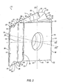
FIGS. 1-5 , acutting insert 10 is shown according to an embodiment of the invention. In general, thecutting insert 10 is tangential and indexable. Thecutting insert 10 is typically manufactured by form-pressing and sintering carbide powders using methods well-known in the art. Thecutting insert 10 is generally rectangular in shape and has two identicalopposing end surfaces 12, two identical opposingminor side surfaces 14 extending between the twoopposing end surfaces 12, two identical opposingmajor side surfaces 16 extending between theend surfaces 12 and theminor side surfaces 14. Eachend surface 12 has 180° rotational symmetry about a first central axis A1 passing through the twoend surfaces 12, eachminor side surface 14 has 180° rotational symmetry about a second central axis A2 passing through the twominor side surfaces 14, and eachmajor side surface 16 has 180° rotational symmetry about a third central axis A3 passing through the twomajor side surfaces 16. The second central axis A2 is perpendicular to the first central axis A1, and the third central axis A3 is perpendicular to the first central axis A1 and to the second central axis A2. Thecutting insert 10 also includes four opposedcorner side surfaces 18 between the minor andmajor side surfaces end surfaces 12. - Each
end surface 12 has four corners; two diagonally opposite loweredcorners 20 and two diagonally opposite raisedcorners 22. The loweredcorners 20 are closer to the second central axis A2 than the raisedcorners 22. Eachcorner side surface 18 extends between theraised corner 22 of one of the two opposingend surfaces 12 and the loweredcorner 20 of the other one of the twoopposing end surfaces 12. Eachend surface 12 is provided with two raisedmembers 24, each raisedmember 24 having asurface 26, and two loweredabutment members 28, each loweredabutment member 28 having ashim abutment surface 30 for contacting theshim 60. Theshim abutment surfaces 30 are diagonally opposite each other with respect to the second central axis A2. As seen inFIGS. 2 and3 , theshim abutment surfaces 30 are substantially coplanar with each other and are substantially parallel with both the second central axis A2 and the third central axis A3. - Two opposing
major edges 32 are formed at the intersection of eachend surface 12 and themajor side surfaces 16, two opposingminor edges 34 are formed at the intersection of eachend surface 12 and theminor side surfaces 14, and twoopposing corner edges 36 are formed at the intersection of each thecorner side surfaces 18 and themajor side surfaces 16. Amajor cutting edge 38 is formed at the intersection of eachmajor edge 32 and theend surface 12 and extends along substantially the entire length of its associatedmajor edge 32. Aminor cutting edge 40 is formed at the intersection of eachminor edge 34 and the end surface and extends along at least half of the length of its associatedminor edge 34. Acorner cutting edge 42 is formed at the intersection of the major andminor cutting edges major cutting edge 38 proximate the raisedcorner 22 constitutes a leadingend 44 of themajor cutting edge 38, whereas the section of themajor cutting edge 38 proximate the loweredcorner 20 constitutes atrailing end 46 of themajor cutting edge 38. - As seen in
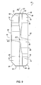
FIG. 3 , theminor edge 34 is divided into three substantially straight sections; a first section 48 extending from the raisedcorner 22 to approximately one-half the distance to the central axis A1; asecond section 50 extending from the first section 48 to approximately the central axis A1; and a third section 52 expending from the central axis A1 to the loweredcorner 20. As seen inFIG. 3 , theminor edge 34 is generally L-shaped when viewed from the side of thecutting insert 10. That is, the first section 48 and the third section 52 are substantially parallel to each other and to the third central axis A3. In other words, the first and third sections 48, 52 do not overlap and do not lie on a common straight line when viewed from the side of thecutting insert 10. - Referring now to
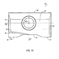
FIGS. 6-10 , ashim 60 is shown according to an embodiment of the invention. In general, theshim 60 is generally rectangular in shape and has two identicalopposing end surfaces 62, two identical opposingminor side surfaces 64 extending between the twoopposing end surfaces 62, two identical opposingmajor side surfaces 66 extending between theend surfaces 62 and theminor side surfaces 64. Eachend surface 62 has 180° rotational symmetry about a first central axis A1 passing through the twoend surfaces 62, eachminor side surface 64 is asymmetric about a second central axis A2 passing through the twominor side surfaces 64, and eachmajor side surface 66 has 180° rotational symmetry about a third central axis A3 passing through the twomajor side surfaces 66. The second central axis A2 is perpendicular to the first central axis A1, and the third central axis A3 is perpendicular to the first central axis A1 and to the second central axis A2. Thecutting insert 10 also includes four opposedcorner side surfaces 68 between the minor andmajor side surfaces end surfaces 62. - Similar to the cutting insert 10, one of the
end surfaces 62 has four comers; two diagonally opposite loweredcorners 70 and two diagonally opposite raisedcorners 72. Unlike the cutting insert 10, theother end surface 62 is substantially planar for engaging the rear wall of the insert pocket, as described below. The loweredcorners 70 are closer to the second central axis A2 than the raisedcorners 72. Eachcorner side surface 68 extends between theraised corner 72 of one of the twoopposing end.surfaces 62 and the loweredcorner 70 of the other one of the twoopposing end surfaces 62. One of theend surfaces 62 is provided with two raisedabutment members 74, each raisedabutment member 74 having aninsert abutment surface 76 for contacting theinsert 10, and two loweredmembers 78, each loweredmember 78 having asurface 80. Theinsert abutment surfaces 76 are diagonally opposite each other with respect to the second central axis A2. As seen inFIGS. 6 and8 , the insert abutment surfaces 76 are substantially coplanar with each other. In addition, the insert abutment surfaces 76 are substantially parallel with both the second central axis A2 and the third central axis A3. - Two opposing
major edges 82 are formed at the intersection of eachend surface 62 and the major side surfaces 66, two opposingminor edges 84 are formed at the intersection of eachend surface 62 and the minor side surfaces 64, and two opposing corner edges 86 are formed at the intersection of each the corner side surfaces 68 and the major side surfaces 66. - As seen in
FIG. 8 , theminor edge 84 is divided into three substantially straight sections; afirst section 88 extending from the raisedcorner 72 to approximately one-half the distance to the central axis A1; asecond section 90 extending from thefirst section 88 to approximately the central axis A1; and athird section 92 extending from the central axis A1 to the loweredcorner 70. As seen inFIG. 8 , theminor edge 84 is generally L-shaped in the side view, similar to theminor edge 34 of the cuttinginsert 10. That is, thefirst section 88 and thethird section 92 are substantially parallel to each other and to the third central axis A3. In other words, the first andthird sections shim 60. - Referring now to
FIGS. 11 and 12 , theinsert 10 and theshim 60 interact with each other to provide additional support to permit proper seating and reduce rotation of the cuttinginsert 10 during heavy machining applications, as compared to conventional cutting inserts and shims. Specifically, the diagonally opposite shim abutment surfaces 26 on theend surface 12 of the cuttinginsert 10 engage the diagonally opposite insert abutment surfaces 76 of theshim 60. This diagonally opposite engagement of the cuttinginsert 10 and theshim 60 is located in anarea 94 where high cutting forces occur during heavy machining applications. Because the cuttinginsert 10 and theshim 60 contact each other in thearea 94 where high cutting forces (and high stress) occur, additional support to permit proper seating and reduced rotation of the cuttinginsert 10 is provided by the cuttinginsert 10 andshim 60 of the invention. - Referring now to
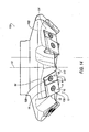
FIGS. 13 and14 , amilling cutter 100 is shown according to an embodiment of the invention. Themilling cutter 100 has an axis of rotation R, and acutter body 102 with a plurality of insert pockets 104. In eachinsert pocket 104, the cuttinginsert 10 andshim 60 of the invention is tangentially mounted to thecutter body 102 by means of a clampingscrew insert 10 is seated so that there is a clearance between a workpiece (not shown) and theminor side surface 14 of the cuttinginsert 10, theminor side surface 64 of theshim 60 and theface 110 of themilling cutter 100. - The
insert pocket 104 includes aside wall 112 and arear wall 114 generally transverse to abottom wall 116. Eachwall insert pocket 104, one of the minor side surfaces 14 of the cuttinginsert 10 is adjacent and engages theside wall 112, and one of the major side surfaces 16 of the cuttinginset 10 is adjacent and engages thebottom wall 116 of theinsert pocket 104. Similarly, one of theminor side surface 64 of theshim 60 is adjacent and engages theside wall 112, and one of the major side surfaces 66 of theshim 60 is adjacent and engages thebottom wall 116 of theinsert pocket 104. In addition, the diagonally opposite shim abutment surfaces 26 on theend surface 12 of the cuttinginsert 10 engages the diagonally opposite insert abutment surfaces 76 of theshim 60 to permit proper seating and reduced rotation of the cuttinginsert 10 during heavy machining operations. - Having descried presently preferred embodiments the invention may be otherwise embodied within the scope of the appended claims.
Claims (10)
- In combination, a cutting insert (10) and shim (60) for heavy machining operations,
the cutting insert (10) comprising two opposing end surfaces (12), two opposing minor side surfaces (14) extending between the two opposing end surfaces (12) and two opposing major side surfaces (16) extending between the end surfaces (12) and the minor side surfaces (14), each end surface (12) of the cutting insert (10) having four corners comprising two lowered corners (20) and two raised corners (22) and
the shim (60) comprising two opposing end surfaces (62), two opposing minor side surfaces (64) extending between the two opposing end surfaces and two opposing major side surfaces (66) extending between the end surfaces and the minor side surfaces,
characterized in that
each end surface (12) is provided with two raised members (24) and two lowered abutment members (28), each lowered abutment member (28) having a shim abutment surface (30), wherein the shim abutment surfaces (30) are diagonally opposite each other with respect to a second, central axis (A2) of the cutting insert, in that
one end surface of the shim (60) has four corners comprising two lowered corners (70) and two raised corners (72), one end surface being provided with two raised abutment members (74) and two lowered members (78), each raised abutment member (74) having an insert abutment surface (76), wherein the insert abutment surfaces are diagonally opposite each other with respect to a second, central axis (A2) of the shim (60), and in that
the shim abutment surfaces (30) of the cutting insert (10) engage the insert abutment surfaces (76) of the shim (60) when the cutting insert (10) and shim (60) are mounted within an insert pocket (104) of a cutting tool (100). - The combination of Claim 1, characterized in that each end surface (12) of the cutting insert (10) has 180° rotational symmetry about a first central axis (A1) passing through the two end surfaces, each minor side surface (14) has 180° rotational symmetry about the second central axis (A2) passing through the two minor side surfaces (14), and each major side surface (16) has 180° rotational symmetry about a third central axis (A3) passing through the two major side surfaces (16), and wherein the second central axis (A2) is perpendicular to the first central axis (A1), and the third central axis (A3) is perpendicular to the first central axis (A1) and to the second central axis (A2).
- The combination of Claim 2, characterized in that the shim abutment surfaces (30) are substantially coplanar with each other and substantially parallel with both the second central axis (A2) and the third central axis (A3) of the cutting insert (10).
- The combination of any of the preceding claims, characterized in that one end surface (62) of the shim (60) has 180° rotational symmetry about a first central axis (A1) passing through the two end surfaces (62), each minor side surface (64) is asymmetric about the second central axis (A2) passing through the two minor side surfaces (64), and each major side surface (66) has 180° rotational symmetry about a third central axis (A3) passing through the two major side surfaces (66), and wherein the second central axis (A2) is perpendicular to the first central axis (A1), and the third central axis (A3) is perpendicular to the first central axis (A1) and to the second central axis (A2).
- The combination of Claim 4, characterized in that the insert abutment surfaces (80) are substantially coplanar with each other and substantially parallel with both the second central axis (A2) and the third central axis (A3) of the shim (60).
- The combination of any of the preceding claims, characterized in that the cutting insert (10) further includes four opposed corner side surfaces (18) between the minor and major side surfaces (14, 16) and the end surfaces (12).
- The combination of Claim 6, characterized in that the cutting insert further includes two opposing major edges (32) formed at an intersection of each end surface (12) and the major side surfaces (14), two opposing minor edges (34) formed at an intersection of each end surface (12) and the minor side surfaces (14), and two opposing corner edges (36) formed at an intersection of each of the corner side surfaces (18) and the major side surfaces (16).
- The combination of Claim 7, characterized in that the cutting insert (10) further includes a major cutting edge (38) formed at an intersection of each major edge (32) and the end surface (12) and extends along substantially an entire length of its associated major edge, and a minor cutting edge (40) formed at an intersection of each minor edge (34) and the end surface (12) and extends along at least half of the length of its associated minor edge, and a corner cutting edge (42) formed at an intersection of the major and minor cutting edges (38, 40).
- The combination of Claim 8, characterized in that a section of the major cutting edge (38) proximate the raised corner (22) constitutes a leading end (44) of the major cutting edge, and wherein a section of the major cutting edge (38) proximate the lowered corner (20) constitutes a trailing end (46) of the major cutting edge (38).
- A milling cutter (100), comprising a plurality of insert pockets (104), characterized in that a combination of a cutting insert (10) and a shim (60) in accordance with any of the preceding claims is seated in each of the plurality, of insert pockets (104).
Applications Claiming Priority (2)
| Application Number | Priority Date | Filing Date | Title |
|---|---|---|---|
| US12/629,535 US8277153B2 (en) | 2009-12-02 | 2009-12-02 | Cutting insert and shim for heavy machining operations |
| PCT/US2010/057239 WO2011068691A2 (en) | 2009-12-02 | 2010-11-18 | Cutting insert and shim for heavy machining operations |
Publications (3)
| Publication Number | Publication Date |
|---|---|
| EP2507003A2 EP2507003A2 (en) | 2012-10-10 |
| EP2507003A4 EP2507003A4 (en) | 2013-05-29 |
| EP2507003B1 true EP2507003B1 (en) | 2014-12-17 |
Family
ID=44050765
Family Applications (1)
| Application Number | Title | Priority Date | Filing Date |
|---|---|---|---|
| EP10834947.3A Active EP2507003B1 (en) | 2009-12-02 | 2010-11-18 | Cutting insert and shim for heavy machining operations |
Country Status (9)
| Country | Link |
|---|---|
| US (1) | US8277153B2 (en) |
| EP (1) | EP2507003B1 (en) |
| JP (1) | JP2013512787A (en) |
| KR (1) | KR20120112416A (en) |
| CN (1) | CN102665983B (en) |
| AU (1) | AU2010326292A1 (en) |
| FR (1) | FR2953156A1 (en) |
| RU (1) | RU2012127276A (en) |
| WO (1) | WO2011068691A2 (en) |
Cited By (1)
| Publication number | Priority date | Publication date | Assignee | Title |
|---|---|---|---|---|
| EP4197678A1 (en) | 2021-12-17 | 2023-06-21 | Seco Tools AB | Double-sided tangential cutting insert |
Families Citing this family (33)
| Publication number | Priority date | Publication date | Assignee | Title |
|---|---|---|---|---|
| DE102006017074A1 (en) * | 2006-04-10 | 2007-10-11 | Walter Ag | Shim for double-sided indexable inserts |
| WO2011021104A1 (en) * | 2009-08-16 | 2011-02-24 | Carmex Precision Tools Ltd. | Insert, support, tool, and method |
| SE534832C2 (en) * | 2010-05-10 | 2012-01-17 | Sandvik Intellectual Property | Indexable cutter for milling tools |
| US8449230B2 (en) * | 2010-08-13 | 2013-05-28 | Ingersoll Cutting Tool Company | Cutting insert having concave clearance depressions formed on corner side surfaces |
| JP5906976B2 (en) * | 2011-10-04 | 2016-04-20 | 三菱マテリアル株式会社 | Cutting insert and cutting edge changeable cutting tool |
| US10035198B2 (en) | 2011-11-15 | 2018-07-31 | Kennametal Inc. | Double-sided, indexable cutting insert with ramping capability and cutting tool therefor |
| US10201856B2 (en) * | 2012-05-24 | 2019-02-12 | Gershon System Ltd. | Method for designing a cutting edge of a cutting tool, cutting tools comprising the same, and cutting elements with multiple such cutting portions |
| SE536855C2 (en) * | 2013-01-23 | 2014-10-07 | Sandvik Intellectual Property | Milling tools with a support plate including an auxiliary cutting edge |
| SE536881C2 (en) | 2013-02-06 | 2014-10-14 | Sandvik Intellectual Property | Device for chip separating machining with support plate |
| JP6352181B2 (en) * | 2013-03-26 | 2018-07-04 | 住友電工ハードメタル株式会社 | Cutting insert and front milling cutter using it |
| US9475136B2 (en) * | 2013-07-30 | 2016-10-25 | Kennametal Inc. | High-speed milling cutter and cutting insert therefor |
| US20150117969A1 (en) * | 2013-10-29 | 2015-04-30 | Kennametal Inc. | Cutting insert and shim for heavy machining operations |
| US9375793B2 (en) | 2013-10-29 | 2016-06-28 | Kennametal Inc. | Cutting insert for heavy machining operations |
| KR101517979B1 (en) * | 2014-07-08 | 2015-05-06 | 한국야금 주식회사 | Cutting insert and cutting tool for mounting the same |
| US10046398B2 (en) * | 2014-12-15 | 2018-08-14 | Seco Tools Ab | Reinforced double-sided cutting insert and cutting tool with reinforced double-sided cutting insert |
| KR101669560B1 (en) * | 2015-04-17 | 2016-11-10 | 한국야금 주식회사 | Cutting insert |
| USD778330S1 (en) | 2015-07-16 | 2017-02-07 | Kennametal Inc. | Double-sided tangential cutting insert |
| USD777230S1 (en) | 2015-07-16 | 2017-01-24 | Kennametal Inc | Double-sided tangential cutting insert |
| US9993884B2 (en) * | 2015-07-16 | 2018-06-12 | Kennametal Inc. | Double-sided tangential cutting insert |
| US9981323B2 (en) | 2015-07-16 | 2018-05-29 | Kennametal Inc. | Double-sided tangential cutting insert and cutting tool system using the same |
| WO2017047700A1 (en) * | 2015-09-15 | 2017-03-23 | 三菱マテリアル株式会社 | Cutting insert and replaceable-blade-type cutting tool |
| KR102301448B1 (en) * | 2016-05-13 | 2021-09-10 | 쎄코 툴스 에이비 | Indexable single-sided cutting inserts having means to prevent improper mounting of the inserts, and cutting tools comprising such inserts |
| JP7008037B2 (en) * | 2016-06-22 | 2022-01-25 | イスカル リミテッド | Lamping inserts and high feed milling tool assemblies |
| JP1568740S (en) * | 2016-09-09 | 2017-02-06 | ||
| US10421134B2 (en) * | 2016-11-17 | 2019-09-24 | Kennametal Inc. | Tangentially mounted indexable cutting insert with convex-shaped minor side surfaces and concave-shaped end surfaces |
| KR101901755B1 (en) * | 2017-03-30 | 2018-09-28 | 한국야금 주식회사 | High feed single-sided cutting insert and cutting tool for mounting the same |
| KR101941973B1 (en) * | 2017-04-11 | 2019-01-24 | 한국야금 주식회사 | High feed cutting insert and cutting tool for mounting the same |
| US10112242B1 (en) | 2017-04-21 | 2018-10-30 | Iscar, Ltd. | Ramping insert having non-positive cutting geometry and ramping tool |
| US10131004B1 (en) | 2017-05-04 | 2018-11-20 | Ingersoll Cutting Tool Company | Cutting insert having non-identical rectangular end surfaces with raised and lowered corner portions and cutting tool |
| US10137510B1 (en) | 2017-05-04 | 2018-11-27 | Ingersoll Cutting Tool Company | Rotary cutting tool having axially supported lead cutting insert and a continuous cutting edge |
| US10427225B2 (en) * | 2017-11-15 | 2019-10-01 | Kennametal Inc. | Tangentially mounted indexable cutting insert with segmented cutting edge and triangular-shaped margin |
| EP3831522A4 (en) * | 2018-08-01 | 2022-05-18 | Kyocera Corporation | Cutting tool and method for producing cut workpiece |
| US11027342B2 (en) * | 2019-03-27 | 2021-06-08 | Iscar, Ltd. | Double-sided cutting insert having diagonally opposed raised corners and diagonally opposed lowered corners, and rotary cutting tool |
Family Cites Families (15)
| Publication number | Priority date | Publication date | Assignee | Title |
|---|---|---|---|---|
| US3694876A (en) * | 1970-08-28 | 1972-10-03 | Ingersoll Milling Machine Co | Indexable cutting insert and holder therefor |
| US4202650A (en) | 1978-10-13 | 1980-05-13 | Kennametal Inc. | Shim lock toolholder |
| US4575287A (en) | 1982-06-11 | 1986-03-11 | Kennametal Inc. | Milling cutter and method of assembling therefor |
| JPH0663812A (en) * | 1992-08-21 | 1994-03-08 | Dijet Ind Co Ltd | Tip fine adjustment device for milling cutter |
| US5292213A (en) | 1992-09-02 | 1994-03-08 | Kennametal Inc. | Coupling device for high-speed rotation |
| IL112818A (en) * | 1995-02-28 | 1999-10-28 | Iscar Ltd | Tool holder having a grooved seat |
| SE503706C2 (en) | 1995-04-11 | 1996-08-05 | Sandvik Ab | Clamping device for cutting tools |
| SE509363C2 (en) * | 1995-09-25 | 1999-01-18 | Sandvik Ab | Fixing device removes cutting plates and cutting plate intended for such device |
| DE10047079A1 (en) | 2000-09-22 | 2002-04-18 | Kennametal Inc | cutting tool |
| IL148535A (en) * | 2002-03-06 | 2009-02-11 | Gil Hecht | Metal cutting tool |
| IL153252A0 (en) | 2002-06-04 | 2003-07-06 | Iscar Ltd | Tangential cutting insert and milling cutter |
| ES2278228T3 (en) | 2002-12-04 | 2007-08-01 | Iscar Ltd. | INSERT PART OF TANGENTIAL CUTTING AND STRAWBERRY. |
| SE525913C2 (en) * | 2002-12-20 | 2005-05-24 | Seco Tools Ab | Cutter, tool and method of mounting the insert where the insert can be oriented in the desired position |
| IL158098A (en) | 2003-09-24 | 2008-03-20 | Amir Satran | Tangential cutting insert and milling cutter |
| IL209396A (en) * | 2010-11-17 | 2015-03-31 | Iscar Ltd | Cutting tool and insert holder for tangential cutting insert |
-
2009
- 2009-12-02 US US12/629,535 patent/US8277153B2/en active Active
-
2010
- 2010-11-18 KR KR1020127013478A patent/KR20120112416A/en not_active Application Discontinuation
- 2010-11-18 RU RU2012127276/02A patent/RU2012127276A/en not_active Application Discontinuation
- 2010-11-18 JP JP2012542075A patent/JP2013512787A/en active Pending
- 2010-11-18 EP EP10834947.3A patent/EP2507003B1/en active Active
- 2010-11-18 CN CN201080053851.2A patent/CN102665983B/en active Active
- 2010-11-18 AU AU2010326292A patent/AU2010326292A1/en not_active Abandoned
- 2010-11-18 WO PCT/US2010/057239 patent/WO2011068691A2/en active Application Filing
- 2010-12-02 FR FR1060037A patent/FR2953156A1/en not_active Withdrawn
Cited By (2)
| Publication number | Priority date | Publication date | Assignee | Title |
|---|---|---|---|---|
| EP4197678A1 (en) | 2021-12-17 | 2023-06-21 | Seco Tools AB | Double-sided tangential cutting insert |
| WO2023110814A1 (en) | 2021-12-17 | 2023-06-22 | Seco Tools Ab | Double-sided tangential cutting insert |
Also Published As
| Publication number | Publication date |
|---|---|
| FR2953156A1 (en) | 2011-06-03 |
| EP2507003A2 (en) | 2012-10-10 |
| RU2012127276A (en) | 2014-01-10 |
| AU2010326292A1 (en) | 2012-05-17 |
| CN102665983A (en) | 2012-09-12 |
| US8277153B2 (en) | 2012-10-02 |
| WO2011068691A3 (en) | 2011-09-22 |
| EP2507003A4 (en) | 2013-05-29 |
| KR20120112416A (en) | 2012-10-11 |
| JP2013512787A (en) | 2013-04-18 |
| WO2011068691A2 (en) | 2011-06-09 |
| CN102665983B (en) | 2014-12-24 |
| US20110129309A1 (en) | 2011-06-02 |
Similar Documents
| Publication | Publication Date | Title |
|---|---|---|
| EP2507003B1 (en) | Cutting insert and shim for heavy machining operations | |
| US9375793B2 (en) | Cutting insert for heavy machining operations | |
| US20150117969A1 (en) | Cutting insert and shim for heavy machining operations | |
| US7909544B2 (en) | Cutting insert and tool for chip removing machining | |
| EP2576113B1 (en) | Milling tool and cutting insert | |
| EP1677934B1 (en) | Tangential cutting insert and milling cutter | |
| US9039335B2 (en) | Indexable, double-sided cutting insert and cutting tool including such an insert | |
| EP2783779B1 (en) | Indexable cutting insert for milling | |
| EP1480774B1 (en) | Tangential cutting insert and insert holder | |
| EP2614907B1 (en) | Cutting insert with angled supporting surface, toolholder with angled abutment surface, and cutting tool | |
| KR101541936B1 (en) | Cutting insert and tool for chip removing machining | |
| US9186732B2 (en) | Cutting insert with grooved surface defining plural support surfaces | |
| US9004823B2 (en) | Family of rotating cutting tools | |
| WO2016186113A1 (en) | Cutting insert, tool body, and cutting tool | |
| WO2003101655A1 (en) | Tangential cutting insert and milling cutter | |
| US9731359B2 (en) | Cutting insert and cutting tool including the same | |
| EP3310511B1 (en) | A rhombus-shaped reversible cutting insert | |
| EP2450138B1 (en) | Cutting insert with grooved surface defining plural support surfaces | |
| JP2016187836A (en) | Cutting insert and cutting edge replaceable cutting tool | |
| KR20220130718A (en) | Rectangular-shaped inserts for bar peeling and insert-holder tools therefor |
Legal Events
| Date | Code | Title | Description |
|---|---|---|---|
| PUAI | Public reference made under article 153(3) epc to a published international application that has entered the european phase |
Free format text: ORIGINAL CODE: 0009012 |
|
| 17P | Request for examination filed |
Effective date: 20120511 |
|
| AK | Designated contracting states |
Kind code of ref document: A2 Designated state(s): AL AT BE BG CH CY CZ DE DK EE ES FI FR GB GR HR HU IE IS IT LI LT LU LV MC MK MT NL NO PL PT RO RS SE SI SK SM TR |
|
| DAX | Request for extension of the european patent (deleted) | ||
| A4 | Supplementary search report drawn up and despatched |
Effective date: 20130503 |
|
| RIC1 | Information provided on ipc code assigned before grant |
Ipc: B23C 5/22 20060101ALI20130425BHEP Ipc: B23C 5/20 20060101AFI20130425BHEP Ipc: B23B 27/16 20060101ALI20130425BHEP |
|
| GRAP | Despatch of communication of intention to grant a patent |
Free format text: ORIGINAL CODE: EPIDOSNIGR1 |
|
| INTG | Intention to grant announced |
Effective date: 20140630 |
|
| GRAS | Grant fee paid |
Free format text: ORIGINAL CODE: EPIDOSNIGR3 |
|
| GRAA | (expected) grant |
Free format text: ORIGINAL CODE: 0009210 |
|
| AK | Designated contracting states |
Kind code of ref document: B1 Designated state(s): AL AT BE BG CH CY CZ DE DK EE ES FI FR GB GR HR HU IE IS IT LI LT LU LV MC MK MT NL NO PL PT RO RS SE SI SK SM TR |
|
| REG | Reference to a national code |
Ref country code: GB Ref legal event code: FG4D |
|
| REG | Reference to a national code |
Ref country code: CH Ref legal event code: EP |
|
| REG | Reference to a national code |
Ref country code: IE Ref legal event code: FG4D |
|
| REG | Reference to a national code |
Ref country code: AT Ref legal event code: REF Ref document number: 701523 Country of ref document: AT Kind code of ref document: T Effective date: 20150115 |
|
| REG | Reference to a national code |
Ref country code: DE Ref legal event code: R096 Ref document number: 602010021188 Country of ref document: DE Effective date: 20150129 |
|
| REG | Reference to a national code |
Ref country code: SE Ref legal event code: TRGR |
|
| PG25 | Lapsed in a contracting state [announced via postgrant information from national office to epo] |
Ref country code: FI Free format text: LAPSE BECAUSE OF FAILURE TO SUBMIT A TRANSLATION OF THE DESCRIPTION OR TO PAY THE FEE WITHIN THE PRESCRIBED TIME-LIMIT Effective date: 20141217 Ref country code: LT Free format text: LAPSE BECAUSE OF FAILURE TO SUBMIT A TRANSLATION OF THE DESCRIPTION OR TO PAY THE FEE WITHIN THE PRESCRIBED TIME-LIMIT Effective date: 20141217 Ref country code: NO Free format text: LAPSE BECAUSE OF FAILURE TO SUBMIT A TRANSLATION OF THE DESCRIPTION OR TO PAY THE FEE WITHIN THE PRESCRIBED TIME-LIMIT Effective date: 20150317 |
|
| REG | Reference to a national code |
Ref country code: LT Ref legal event code: MG4D |
|
| PG25 | Lapsed in a contracting state [announced via postgrant information from national office to epo] |
Ref country code: HR Free format text: LAPSE BECAUSE OF FAILURE TO SUBMIT A TRANSLATION OF THE DESCRIPTION OR TO PAY THE FEE WITHIN THE PRESCRIBED TIME-LIMIT Effective date: 20141217 Ref country code: RS Free format text: LAPSE BECAUSE OF FAILURE TO SUBMIT A TRANSLATION OF THE DESCRIPTION OR TO PAY THE FEE WITHIN THE PRESCRIBED TIME-LIMIT Effective date: 20141217 Ref country code: LV Free format text: LAPSE BECAUSE OF FAILURE TO SUBMIT A TRANSLATION OF THE DESCRIPTION OR TO PAY THE FEE WITHIN THE PRESCRIBED TIME-LIMIT Effective date: 20141217 Ref country code: GR Free format text: LAPSE BECAUSE OF FAILURE TO SUBMIT A TRANSLATION OF THE DESCRIPTION OR TO PAY THE FEE WITHIN THE PRESCRIBED TIME-LIMIT Effective date: 20150318 |
|
| REG | Reference to a national code |
Ref country code: AT Ref legal event code: MK05 Ref document number: 701523 Country of ref document: AT Kind code of ref document: T Effective date: 20141217 |
|
| PG25 | Lapsed in a contracting state [announced via postgrant information from national office to epo] |
Ref country code: NL Free format text: LAPSE BECAUSE OF FAILURE TO SUBMIT A TRANSLATION OF THE DESCRIPTION OR TO PAY THE FEE WITHIN THE PRESCRIBED TIME-LIMIT Effective date: 20141217 |
|
| PG25 | Lapsed in a contracting state [announced via postgrant information from national office to epo] |
Ref country code: EE Free format text: LAPSE BECAUSE OF FAILURE TO SUBMIT A TRANSLATION OF THE DESCRIPTION OR TO PAY THE FEE WITHIN THE PRESCRIBED TIME-LIMIT Effective date: 20141217 Ref country code: ES Free format text: LAPSE BECAUSE OF FAILURE TO SUBMIT A TRANSLATION OF THE DESCRIPTION OR TO PAY THE FEE WITHIN THE PRESCRIBED TIME-LIMIT Effective date: 20141217 Ref country code: SK Free format text: LAPSE BECAUSE OF FAILURE TO SUBMIT A TRANSLATION OF THE DESCRIPTION OR TO PAY THE FEE WITHIN THE PRESCRIBED TIME-LIMIT Effective date: 20141217 Ref country code: RO Free format text: LAPSE BECAUSE OF FAILURE TO SUBMIT A TRANSLATION OF THE DESCRIPTION OR TO PAY THE FEE WITHIN THE PRESCRIBED TIME-LIMIT Effective date: 20141217 Ref country code: CZ Free format text: LAPSE BECAUSE OF FAILURE TO SUBMIT A TRANSLATION OF THE DESCRIPTION OR TO PAY THE FEE WITHIN THE PRESCRIBED TIME-LIMIT Effective date: 20141217 |
|
| PG25 | Lapsed in a contracting state [announced via postgrant information from national office to epo] |
Ref country code: AT Free format text: LAPSE BECAUSE OF FAILURE TO SUBMIT A TRANSLATION OF THE DESCRIPTION OR TO PAY THE FEE WITHIN THE PRESCRIBED TIME-LIMIT Effective date: 20141217 Ref country code: PL Free format text: LAPSE BECAUSE OF FAILURE TO SUBMIT A TRANSLATION OF THE DESCRIPTION OR TO PAY THE FEE WITHIN THE PRESCRIBED TIME-LIMIT Effective date: 20141217 Ref country code: IS Free format text: LAPSE BECAUSE OF FAILURE TO SUBMIT A TRANSLATION OF THE DESCRIPTION OR TO PAY THE FEE WITHIN THE PRESCRIBED TIME-LIMIT Effective date: 20150417 |
|
| REG | Reference to a national code |
Ref country code: DE Ref legal event code: R097 Ref document number: 602010021188 Country of ref document: DE |
|
| PLBE | No opposition filed within time limit |
Free format text: ORIGINAL CODE: 0009261 |
|
| STAA | Information on the status of an ep patent application or granted ep patent |
Free format text: STATUS: NO OPPOSITION FILED WITHIN TIME LIMIT |
|
| PG25 | Lapsed in a contracting state [announced via postgrant information from national office to epo] |
Ref country code: DK Free format text: LAPSE BECAUSE OF FAILURE TO SUBMIT A TRANSLATION OF THE DESCRIPTION OR TO PAY THE FEE WITHIN THE PRESCRIBED TIME-LIMIT Effective date: 20141217 |
|
| 26N | No opposition filed |
Effective date: 20150918 |
|
| PG25 | Lapsed in a contracting state [announced via postgrant information from national office to epo] |
Ref country code: IT Free format text: LAPSE BECAUSE OF FAILURE TO SUBMIT A TRANSLATION OF THE DESCRIPTION OR TO PAY THE FEE WITHIN THE PRESCRIBED TIME-LIMIT Effective date: 20141217 |
|
| PG25 | Lapsed in a contracting state [announced via postgrant information from national office to epo] |
Ref country code: SI Free format text: LAPSE BECAUSE OF FAILURE TO SUBMIT A TRANSLATION OF THE DESCRIPTION OR TO PAY THE FEE WITHIN THE PRESCRIBED TIME-LIMIT Effective date: 20141217 |
|
| PG25 | Lapsed in a contracting state [announced via postgrant information from national office to epo] |
Ref country code: BE Free format text: LAPSE BECAUSE OF FAILURE TO SUBMIT A TRANSLATION OF THE DESCRIPTION OR TO PAY THE FEE WITHIN THE PRESCRIBED TIME-LIMIT Effective date: 20141217 |
|
| PG25 | Lapsed in a contracting state [announced via postgrant information from national office to epo] |
Ref country code: MC Free format text: LAPSE BECAUSE OF FAILURE TO SUBMIT A TRANSLATION OF THE DESCRIPTION OR TO PAY THE FEE WITHIN THE PRESCRIBED TIME-LIMIT Effective date: 20141217 Ref country code: LU Free format text: LAPSE BECAUSE OF FAILURE TO SUBMIT A TRANSLATION OF THE DESCRIPTION OR TO PAY THE FEE WITHIN THE PRESCRIBED TIME-LIMIT Effective date: 20151118 |
|
| REG | Reference to a national code |
Ref country code: CH Ref legal event code: PL |
|
| GBPC | Gb: european patent ceased through non-payment of renewal fee |
Effective date: 20151118 |
|
| PG25 | Lapsed in a contracting state [announced via postgrant information from national office to epo] |
Ref country code: LI Free format text: LAPSE BECAUSE OF NON-PAYMENT OF DUE FEES Effective date: 20151130 Ref country code: CH Free format text: LAPSE BECAUSE OF NON-PAYMENT OF DUE FEES Effective date: 20151130 |
|
| REG | Reference to a national code |
Ref country code: IE Ref legal event code: MM4A |
|
| REG | Reference to a national code |
Ref country code: FR Ref legal event code: ST Effective date: 20160729 |
|
| PG25 | Lapsed in a contracting state [announced via postgrant information from national office to epo] |
Ref country code: SE Free format text: LAPSE BECAUSE OF NON-PAYMENT OF DUE FEES Effective date: 20151119 |
|
| PG25 | Lapsed in a contracting state [announced via postgrant information from national office to epo] |
Ref country code: GB Free format text: LAPSE BECAUSE OF NON-PAYMENT OF DUE FEES Effective date: 20151118 Ref country code: IE Free format text: LAPSE BECAUSE OF NON-PAYMENT OF DUE FEES Effective date: 20151118 |
|
| PG25 | Lapsed in a contracting state [announced via postgrant information from national office to epo] |
Ref country code: FR Free format text: LAPSE BECAUSE OF NON-PAYMENT OF DUE FEES Effective date: 20151130 |
|
| PG25 | Lapsed in a contracting state [announced via postgrant information from national office to epo] |
Ref country code: HU Free format text: LAPSE BECAUSE OF FAILURE TO SUBMIT A TRANSLATION OF THE DESCRIPTION OR TO PAY THE FEE WITHIN THE PRESCRIBED TIME-LIMIT; INVALID AB INITIO Effective date: 20101118 Ref country code: BG Free format text: LAPSE BECAUSE OF FAILURE TO SUBMIT A TRANSLATION OF THE DESCRIPTION OR TO PAY THE FEE WITHIN THE PRESCRIBED TIME-LIMIT Effective date: 20141217 Ref country code: SM Free format text: LAPSE BECAUSE OF FAILURE TO SUBMIT A TRANSLATION OF THE DESCRIPTION OR TO PAY THE FEE WITHIN THE PRESCRIBED TIME-LIMIT Effective date: 20141217 |
|
| PG25 | Lapsed in a contracting state [announced via postgrant information from national office to epo] |
Ref country code: CY Free format text: LAPSE BECAUSE OF FAILURE TO SUBMIT A TRANSLATION OF THE DESCRIPTION OR TO PAY THE FEE WITHIN THE PRESCRIBED TIME-LIMIT Effective date: 20141217 |
|
| PG25 | Lapsed in a contracting state [announced via postgrant information from national office to epo] |
Ref country code: MT Free format text: LAPSE BECAUSE OF FAILURE TO SUBMIT A TRANSLATION OF THE DESCRIPTION OR TO PAY THE FEE WITHIN THE PRESCRIBED TIME-LIMIT Effective date: 20141217 |
|
| PG25 | Lapsed in a contracting state [announced via postgrant information from national office to epo] |
Ref country code: MK Free format text: LAPSE BECAUSE OF FAILURE TO SUBMIT A TRANSLATION OF THE DESCRIPTION OR TO PAY THE FEE WITHIN THE PRESCRIBED TIME-LIMIT Effective date: 20141217 Ref country code: TR Free format text: LAPSE BECAUSE OF FAILURE TO SUBMIT A TRANSLATION OF THE DESCRIPTION OR TO PAY THE FEE WITHIN THE PRESCRIBED TIME-LIMIT Effective date: 20141217 |
|
| PG25 | Lapsed in a contracting state [announced via postgrant information from national office to epo] |
Ref country code: PT Free format text: LAPSE BECAUSE OF FAILURE TO SUBMIT A TRANSLATION OF THE DESCRIPTION OR TO PAY THE FEE WITHIN THE PRESCRIBED TIME-LIMIT Effective date: 20141217 |
|
| PG25 | Lapsed in a contracting state [announced via postgrant information from national office to epo] |
Ref country code: AL Free format text: LAPSE BECAUSE OF FAILURE TO SUBMIT A TRANSLATION OF THE DESCRIPTION OR TO PAY THE FEE WITHIN THE PRESCRIBED TIME-LIMIT Effective date: 20141217 |
|
| P01 | Opt-out of the competence of the unified patent court (upc) registered |
Effective date: 20230622 |
|
| PGFP | Annual fee paid to national office [announced via postgrant information from national office to epo] |
Ref country code: DE Payment date: 20231129 Year of fee payment: 14 |