EP2506610A2 - Method and apparatus to improve high-speed mobility in a wireless communication system - Google Patents
Method and apparatus to improve high-speed mobility in a wireless communication system Download PDFInfo
- Publication number
- EP2506610A2 EP2506610A2 EP12002264A EP12002264A EP2506610A2 EP 2506610 A2 EP2506610 A2 EP 2506610A2 EP 12002264 A EP12002264 A EP 12002264A EP 12002264 A EP12002264 A EP 12002264A EP 2506610 A2 EP2506610 A2 EP 2506610A2
- Authority
- EP
- European Patent Office
- Prior art keywords
- location
- information related
- enb
- processor
- message
- Prior art date
- Legal status (The legal status is an assumption and is not a legal conclusion. Google has not performed a legal analysis and makes no representation as to the accuracy of the status listed.)
- Withdrawn
Links
- 238000000034 method Methods 0.000 title claims abstract description 60
- 238000004891 communication Methods 0.000 title claims description 33
- 230000005540 biological transmission Effects 0.000 claims abstract description 6
- 238000005259 measurement Methods 0.000 claims description 11
- 230000001960 triggered effect Effects 0.000 claims description 3
- 238000010586 diagram Methods 0.000 description 7
- 230000008569 process Effects 0.000 description 7
- 230000001143 conditioned effect Effects 0.000 description 3
- 238000013461 design Methods 0.000 description 3
- 239000011159 matrix material Substances 0.000 description 3
- 238000012545 processing Methods 0.000 description 3
- 238000004590 computer program Methods 0.000 description 2
- 230000006870 function Effects 0.000 description 2
- 230000007774 longterm Effects 0.000 description 2
- 238000010295 mobile communication Methods 0.000 description 2
- 230000003287 optical effect Effects 0.000 description 2
- 239000002245 particle Substances 0.000 description 2
- 230000011664 signaling Effects 0.000 description 2
- 101150059691 GPP2 gene Proteins 0.000 description 1
- 108700026140 MAC combination Proteins 0.000 description 1
- 230000006978 adaptation Effects 0.000 description 1
- 238000013459 approach Methods 0.000 description 1
- 230000008901 benefit Effects 0.000 description 1
- 230000000295 complement effect Effects 0.000 description 1
- 230000001419 dependent effect Effects 0.000 description 1
- 238000005516 engineering process Methods 0.000 description 1
- GVVPGTZRZFNKDS-JXMROGBWSA-N geranyl diphosphate Chemical compound CC(C)=CCC\C(C)=C\CO[P@](O)(=O)OP(O)(O)=O GVVPGTZRZFNKDS-JXMROGBWSA-N 0.000 description 1
- 230000000977 initiatory effect Effects 0.000 description 1
- 238000012986 modification Methods 0.000 description 1
- 230000004048 modification Effects 0.000 description 1
- 230000008520 organization Effects 0.000 description 1
- 239000005022 packaging material Substances 0.000 description 1
- 230000000737 periodic effect Effects 0.000 description 1
- 230000004044 response Effects 0.000 description 1
- 238000012546 transfer Methods 0.000 description 1
Images


Classifications
-
- H—ELECTRICITY
- H04—ELECTRIC COMMUNICATION TECHNIQUE
- H04W—WIRELESS COMMUNICATION NETWORKS
- H04W4/00—Services specially adapted for wireless communication networks; Facilities therefor
- H04W4/20—Services signaling; Auxiliary data signalling, i.e. transmitting data via a non-traffic channel
-
- H—ELECTRICITY
- H04—ELECTRIC COMMUNICATION TECHNIQUE
- H04W—WIRELESS COMMUNICATION NETWORKS
- H04W36/00—Hand-off or reselection arrangements
- H04W36/08—Reselecting an access point
-
- H—ELECTRICITY
- H04—ELECTRIC COMMUNICATION TECHNIQUE
- H04W—WIRELESS COMMUNICATION NETWORKS
- H04W24/00—Supervisory, monitoring or testing arrangements
- H04W24/10—Scheduling measurement reports ; Arrangements for measurement reports
-
- H—ELECTRICITY
- H04—ELECTRIC COMMUNICATION TECHNIQUE
- H04W—WIRELESS COMMUNICATION NETWORKS
- H04W36/00—Hand-off or reselection arrangements
- H04W36/0005—Control or signalling for completing the hand-off
- H04W36/0011—Control or signalling for completing the hand-off for data sessions of end-to-end connection
- H04W36/0016—Hand-off preparation specially adapted for end-to-end data sessions
-
- H—ELECTRICITY
- H04—ELECTRIC COMMUNICATION TECHNIQUE
- H04W—WIRELESS COMMUNICATION NETWORKS
- H04W4/00—Services specially adapted for wireless communication networks; Facilities therefor
- H04W4/02—Services making use of location information
- H04W4/025—Services making use of location information using location based information parameters
- H04W4/027—Services making use of location information using location based information parameters using movement velocity, acceleration information
-
- H—ELECTRICITY
- H04—ELECTRIC COMMUNICATION TECHNIQUE
- H04W—WIRELESS COMMUNICATION NETWORKS
- H04W64/00—Locating users or terminals or network equipment for network management purposes, e.g. mobility management
- H04W64/006—Locating users or terminals or network equipment for network management purposes, e.g. mobility management with additional information processing, e.g. for direction or speed determination
-
- H—ELECTRICITY
- H04—ELECTRIC COMMUNICATION TECHNIQUE
- H04W—WIRELESS COMMUNICATION NETWORKS
- H04W76/00—Connection management
- H04W76/10—Connection setup
-
- H—ELECTRICITY
- H04—ELECTRIC COMMUNICATION TECHNIQUE
- H04W—WIRELESS COMMUNICATION NETWORKS
- H04W80/00—Wireless network protocols or protocol adaptations to wireless operation
- H04W80/02—Data link layer protocols
-
- H—ELECTRICITY
- H04—ELECTRIC COMMUNICATION TECHNIQUE
- H04W—WIRELESS COMMUNICATION NETWORKS
- H04W92/00—Interfaces specially adapted for wireless communication networks
- H04W92/16—Interfaces between hierarchically similar devices
- H04W92/20—Interfaces between hierarchically similar devices between access points
Definitions
- This disclosure generally relates to wireless communication networks, and more particularly, to a method and apparatus to improve high-speed mobility in a wireless communication system.
- IP Internet Protocol
- E-UTRAN Evolved Universal Terrestrial Radio Access Network
- the E-UTRAN system can provide high data throughput in order to realize the above-noted voice over IP and multimedia services.
- the E-UTRAN system's standardization work is currently being performed by the 3GPP standards organization. Accordingly, changes to the current body of 3GPP standard are currently being submitted and considered to evolve and finalize the 3GPP standard.
- the method comprises connecting a device to a cell.
- the method also comprises maintaining, at the device, information related to a location of the device.
- the method further comprises triggering, by an event trigger related to a velocity of the device, a transmission of a report that includes the information related to the location of the device.
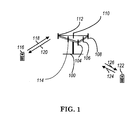
- FIG. 1 shows a diagram of a wireless communication system according to one exemplary embodiment.
- FIG. 2 is a block diagram of a transmitter system (also known as access network) and a receiver system (also known as user equipment or UE) according to one exemplary embodiment.
- a transmitter system also known as access network
- a receiver system also known as user equipment or UE
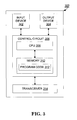
- FIG. 3 is a functional block diagram of a communication system according to one exemplary embodiment.
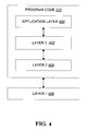
- FIG. 4 is a functional block diagram of the program code of FIG. 3 according to one exemplary embodiment.
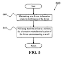
- FIG. 5 is a flow chart according to one exemplary embodiment.
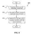
- FIG. 6 is a flow chart according to one exemplary embodiment.
- FIG. 7 is a flow chart according to one exemplary embodiment.
- Wireless communication systems are widely deployed to provide various types of communication such as voice, data, and so on. These systems may be based on code division multiple access (CDMA), time division multiple access (TDMA), orthogonal frequency division multiple access (OFDMA), 3GPP LTE (Long Term Evolution) wireless access, 3GPP LTE-A or LTE-Advanced (Long Term Evolution Advanced), 3 GPP2 UMB (Ultra Mobile Broadband), WiMax, or some other modulation techniques.
- CDMA code division multiple access
- TDMA time division multiple access
- OFDMA orthogonal frequency division multiple access
- 3GPP LTE Long Term Evolution
- 3GPP LTE-A or LTE-Advanced Long Term Evolution Advanced
- 3 GPP2 UMB Ultra Mobile Broadband
- WiMax Worldwide Interoperability for Mobile communications
- the exemplary wireless communication systems devices described below may be designed to support one or more standards such as the standard offered by a consortium named "3rd Generation Partnership Project” referred to herein as 3GPP, including Document Nos. TS 36.321 V10.0.0, "MAC protocol specification (Release 10)”; TS 36.331-V10.0.0, “RRC protocol specification (Release 10)”; RP-110398, “New Study Item Proposal: Mobile Relay for EUTRA”; TS 36.300 V10.2.0, “E-UTRA and E-UTRAN; Overall description; Stage 2"; TS 36.355 V10.0.0, “LTE Positioning Protocol”; TS 36.305 V10.0.0, “Stage 2 functional specification ofUE positioning in E-UTRAN”; TS 36.423 V10.0.0, “E-UTRAN X2AP (Release 10)".
- 3GPP 3rd Generation Partnership Project
- FIG. 1 shows a multiple access wireless communication system according to one embodiment of the invention.
- An access network 100 includes multiple antenna groups, one including 104 and 106, another including 108 and 110, and an additional including 112 and 114. In FIG. 1 , only two antennas are shown for each antenna group, however, more or fewer antennas may be utilized for each antenna group.
- Access terminal 116 is in communication with antennas 112 and 114, where antennas 112 and 114 transmit information to access terminal 116 over forward link 120 and receive information from access terminal 116 over reverse link 118.
- Access terminal (AT) 122 is in communication with antennas 106 and 108, where antennas 106 and 108 transmit information to access terminal (AT) 122 over forward link 126 and receive information from access terminal (AT) 122 over reverse link 124.
- communication links 118, 120, 124 and 126 may use different frequency for communication.
- forward link 120 may use a different frequency then that used by reverse link 118.
- antenna groups each are designed to communicate to access terminals in a sector of the areas covered by access network 100.
- the transmitting antennas of access network 100 may utilize beamforming in order to improve the signal-to-noise ratio of forward links for the different access terminals 116 and 122. Also, an access network using beamforming to transmit to access terminals scattered randomly through its coverage causes less interference to access terminals in neighboring cells than an access network transmitting through a single antenna to all its access terminals.
- An access network may be a fixed station or base station used for communicating with the terminals and may also be referred to as an access point, a Node B, a base station, an enhanced base station, an eNodeB, or some other terminology.
- An access terminal may also be called user equipment (UE), a relay node (RN), a wireless communication device, terminal, access terminal or some other terminology.
- FIG. 2 is a simplified block diagram of an embodiment of a transmitter system 210 (also known as the access network) and a receiver system 250 (also known as access terminal (AT) or user equipment (UE) or relay node (RN)) in a MIMO system 200.
- a transmitter system 210 also known as the access network
- a receiver system 250 also known as access terminal (AT) or user equipment (UE) or relay node (RN)
- AT access terminal
- UE user equipment
- RN relay node
- each data stream is transmitted over a respective transmit antenna.
- TX data processor 214 formats, codes, and interleaves the traffic data for each data stream based on a particular coding scheme selected for that data stream to provide coded data.
- the coded data for each data stream may be multiplexed with pilot data using OFDM techniques.
- the pilot data is typically a known data pattern that is processed in a known manner and may be used at the receiver system to estimate the channel response.
- the multiplexed pilot and coded data for each data stream is then modulated (i.e., symbol mapped) based on a particular modulation scheme (e.g., BPSK, QPSK, M-PSK, or M-QAM) selected for that data stream to provide modulation symbols.
- a particular modulation scheme e.g., BPSK, QPSK, M-PSK, or M-QAM
- the data rate, coding, and modulation for each data stream may be determined by instructions performed by processor 230.
- TX MIMO processor 220 may further process the modulation symbols (e.g., for OFDM).
- TX MIMO processor 220 then provides N T modulation symbol streams to N T transmitters (TMTR) 222a through 222t.
- TMTR TX MIMO processor 220 applies beamforming weights to the symbols of the data streams and to the antenna from which the symbol is being transmitted.
- Each transmitter 222 receives and processes a respective symbol stream to provide one or more analog signals, and further conditions (e.g., amplifies, filters, and upconverts) the analog signals to provide a modulated signal suitable for transmission over the MIMO channel.
- N T modulated signals from transmitters 222a through 222t are then transmitted from N T antennas 224a through 224t, respectively.
- the transmitted modulated signals are received by N R antennas 252a through 252r and the received signal from each antenna 252 is provided to a respective receiver (RCVR) 254a through 254r.
- Each receiver 254 conditions (e.g., filters, amplifies, and downconverts) a respective received signal, digitizes the conditioned signal to provide samples, and further processes the samples to provide a corresponding "received" symbol stream.
- An RX data processor 260 then receives and processes the N R received symbol streams from N R receivers 254 based on a particular receiver processing technique to provide N T "detected" symbol streams.
- the RX data processor 260 then demodulates, deinterleaves, and decodes each detected symbol stream to recover the traffic data for the data stream.
- the processing by RX data processor 260 is complementary to that performed by TX MIMO processor 220 and TX data processor 214 at transmitter system 210.
- a processor 270 periodically determines which pre-coding matrix to use (discussed below). Processor 270 formulates a reverse link message comprising a matrix index portion and a rank value portion.
- the reverse link message may comprise various types of information regarding the communication link and/or the received data stream.
- the reverse link message is then processed by a TX data processor 238, which also receives traffic data for a number of data streams from a data source 236, modulated by a modulator 280, conditioned by transmitters 254a through 254r, and transmitted back to transmitter system 210.
- the modulated signals from receiver system 250 are received by antennas 224, conditioned by receivers 222, demodulated by a demodulator 240, and processed by a RX data processor 242 to extract the reserve link message transmitted by the receiver system 250.
- Processor 230 determines which pre-coding matrix to use for determining the beamforming weights then processes the extracted message.
- FIG. 3 shows an alternative simplified functional block diagram of a communication device according to one embodiment of the invention.
- the communication device 300 in a wireless communication system can be utilized for realizing the UEs (or ATs or RNs) 116 and 122 in FIG. 1 , and the wireless communications system is preferably the LTE-A system.
- the communication device 300 may include an input device 302, an output device 304, a control circuit 306, a central processing unit (CPU) 308, a memory 310, a program code 312, and a transceiver 314.
- the control circuit 306 executes the program code 312 in the memory 310 through the CPU 308, thereby controlling an operation of the communications device 300.
- the communications device 300 can receive signals input by a user through the input device 302, such as a keyboard or keypad, and can output images and sounds through the output device 304, such as a monitor or speakers.
- the transceiver 314 is used to receive and transmit wireless signals, delivering received signals to the control circuit 306, and outputting signals generated by the control circuit 306 wirelessly.
- FIG. 4 is a simplified block diagram of the program code 312 shown in FIG. 3 in accordance with one embodiment of the invention.
- the program code 312 includes an application layer 400, a Layer 3 portion 402, and a Layer 2 portion 404, and is coupled to a Layer 1 portion 406.
- the Layer 3 portion 402 generally performs radio resource control.
- the Layer 2 portion 404 generally performs link control.
- the Layer 1 portion 406 generally performs physical connections.
- 3GPP RP-110398 proposes a new Study Item about Mobile Relay for Evolved Universal Terrestrial Radio Access (EUTRA).
- EUTRA Evolved Universal Terrestrial Radio Access
- 3GPP RP-110398 proposes a new Study Item about Mobile Relay for Evolved Universal Terrestrial Radio Access (EUTRA).
- EUTRA Evolved Universal Terrestrial Radio Access
- handover occurs much more frequent;
- UE measurements in high speed environments are typically less accurate than low speed environments.
- Mobile relay node e.g., a relay node mounted on a vehicle wirelessly connected to the macro cells
- Mobile relay node is considered to be a potential technique to solve the problem.
- Information related to a stationary relay node can be found in 3GPP TS 36.331 V10.0.0 and TS 36.300 V10.2.0.
- the Relay Node (RN) startup procedure is described in 3GPP TS 36.300 V10.2.0 as follows:
- the relay node operates as a UE and retrieves a list of DeNB (Donor evolved Node B) cells that are allowed to access during Phase I of the RN startup procedure.
- the relay node operates as a relay node and connects to a DeNB during Phase II.
- inter-cell handover is not supported for (stationary) relay nodes.
- the LocationInfo information element is used in RRC layer to transfer location information available at the UE, as discussed in 3GPP TS 36.331 V10.0.0.
- the LocationInfo information element may be included in a MeasurementReport message or a UEInformationResponse message.
- the LocationInfo information element includes the position and the velocity of the UE.
- the detailed content of LocationInfo information element is specified in 3GPP TS 36.331 V10.0.0 as follows: LocationInfo field descriptions ellipsoid-Point Parameter Ellipsoid-Point defined in TS 36.355. ellipsoidPointwithAltitude Parameter EllipsoidPointWithAltitude defined in TS 36.355. horizontalVelocity Parameter HorizontalVelocity defined in TS 36.355.
- the ProvideLocationInformation message (or LPP Provide Location Information message as specified in 3GPP TS 36.305 V10.0.0) is used by the target device (e.g., UE) to provide positioning measurements or position estimates in LTE Positioning Protocol (LPP) layer to the location server, such as E-SMLC (Evolved Serving Mobile Location Centre).
- LPP LTE Positioning Protocol
- handover to another cell may need to be initiated promptly due to high speed movement.
- eNB may not know that a UE is moving in high speed. Accordingly, initiating a handover procedure after receiving a measurement report may be too late and may result in RRC connection re-establishment. More information would be helpful for eNB to initiate a handover (such as a blind handover) intelligently.
- a device could provide information related to its location (such as position, velocity, or measurement results) upon connecting to a cell (for example, by initial access, connection re-establishment, or handover) as described in 3GPP TS 36.331 V10.0.0.
- a report (which includes information related to the position and/or velocity of a device) could be triggered by an event trigger which is related to the velocity of the device.
- the report could be carried by a RRC message (such as a MeasurementReport message - described in 3GPP TS 36.331 V10.0.0), or a MAC control element (described in 3GPP TS 36.321 V10.0.0).
- a source eNB could provide information related to location of a device to a target eNB during the handover preparation phase.
- the information related to location could include position, velocity, or measurement results.
- the location information could be provided through, for example, a HandoverPreparationlnformation message (described in 3GPP TS 36.331 V10.0.0) or a Handover Request message (described in 3GPP TS 36.423 V10.0.0).
- the device can be a UE or a mobile relay node.
- FIG. 5 illustrates a flow chart 500 in accordance with one exemplary embodiment.
- the device keeps and maintains information related to its location.
- the device provides to the network the information related to the location of the device when the device connects to a cell.
- the location information of the device could be carried by or provided through a RRCConnectionSetupComplete message, a RRCConnectionReestablishmentComplete message, or a RRCConnectionReconfigurationComplete message for a handover procedure, which are described in 3GPP TS 36.331 V10.0.0.
- the cell may not be controlled by a mobile relay node.
- the UE (or a relay node) 300 includes a program code 312 stored in memory 310.
- the CPU 308 could execute the program code 312 (i) to maintaining, at a device, information related to the location of the device, and (ii) to provide, from the device to a network, the information related to the location of the device when the device connects to a cell in the network.
- FIG. 6 illustrates a flow chart 600 in accordance with one exemplary embodiment.
- a device is being connected to a cell, and is entering the RRC_CONNECTED state.
- the device keeps and maintains information related to its location.
- an event trigger related to the velocity of the device could be used to trigger the transmission of a report that includes the information related to the location of the device.
- the event trigger is that the report is triggered when the velocity of the device becomes higher (or lower) than a threshold.
- the device could be configured to enable the transmission of the report. And the report is not prohibited, for example, by a prohibit timer.
- the device could connect to the cell by a RRC connection establishment procedure, a RRC connection re-establishment procedure, or a handover procedure.
- the cell may not be controlled by a mobile relay node.
- the UE (or a relay node) 300 includes a program code 312 stored in memory 310.
- the CPU 308 could execute the program code 312 (i) to connect a device to a cell, (ii) to maintain, at the device, information related to a location of the device, and (iii) to trigger, by an event trigger related to a velocity of the device, a report that includes the information related to the location of the device.
- FIG. 7 illustrates a flow chart 700 in accordance with one exemplary embodiment.
- a first eNB is connected by a device.
- the first eNB receives information related to the location of the device.
- the first eNB sends, to a second eNB, the information related to the location of the device.
- a first eNB 300 includes a program code 312 stored in memory 310.
- the CPU 308 could execute the program code 312 (i) to have the first eNB connected by the device, (ii) to receive, at the first eNB, information related to the location of the device, and (iii) to send the information related to the location of the device from the first eNB to a second eNB.
- the CPU 308 can execute the program code 312 to perform all of the described actions and steps or others described herein.
- the device could be a mobile relay node or a UE.
- the device may be moving in high speed, such that it could, for example, be judged by a threshold.
- the information related to the location of the device may include position of the device which could be expressed by latitude and longitude.
- the information related to the location of the device may include velocity of the device which could be expressed by speed or bearing.
- the information related to the location of the device may include measurement results which are used to estimate the location of the device, and (ii) may be carried by a LocalionInfo information element or a ProvideLocationInformation message (which may be carried by an ULInformationTransfer message described in 3GPP TS 36.423 V10.0.0).
- the information related to the location of the device may include an indication that the device is moving in high speed, e.g. which is judged by a threshold.
- the device could determine its position and/or velocity by supporting Global Navigation Satellite System (GNSS), Observed Time Difference of Arrival (OTDOA), Assisted Global Navigation Satellite System (A-GNSS), Enhanced Cell-ID (E-CID) positioning method (described in 3GPP TS 36.355 V10.0.0 or TS 36.305 V10.0.0), or LTE Positioning Protocol (LPP).
- GNSS Global Navigation Satellite System
- OTDA Observed Time Difference of Arrival
- A-GNSS Assisted Global Navigation Satellite System
- E-CID Enhanced Cell-ID positioning method
- LPP LTE Positioning Protocol
- concurrent channels may be established based on pulse repetition frequencies.
- concurrent channels may be established based on pulse position or offsets.
- concurrent channels may be established based on time hopping sequences.
- concurrent channels may be established based on pulse repetition frequencies, pulse positions or offsets, and time hopping sequences.
- the various illustrative logical blocks, modules, and circuits described in connection with the aspects disclosed herein may be implemented within or performed by an integrated circuit ("IC"), an access terminal, or an access point.
- the IC may comprise a general purpose processor, a digital signal processor (DSP), an application specific integrated circuit (ASIC), a field programmable gate array (FPGA) or other programmable logic device, discrete gate or transistor logic, discrete hardware components, electrical components, optical components, mechanical components, or any combination thereof designed to perform the functions described herein, and may execute codes or instructions that reside within the IC, outside of the IC, or both.
- a general purpose processor may be a microprocessor, but in the alternative, the processor may be any conventional processor, controller, microcontroller, or state machine.
- a processor may also be implemented as a combination of computing devices, e.g., a combination of a DSP and a microprocessor, a plurality of microprocessors, one or more microprocessors in conjunction with a DSP core, or any other such configuration.
- a software module e.g., including executable instructions and related data
- other data may reside in a data memory such as RAM memory, flash memory, ROM memory, EPROM memory, EEPROM memory, registers, a hard disk, a removable disk, a CD-ROM, or any other form of computer-readable storage medium known in the art.
- a sample storage medium may be coupled to a machine such as, for example, a computer/processor (which may be referred to herein, for convenience, as a "processor") such the processor can read information (e.g., code) from and write information to the storage medium.
- a sample storage medium may be integral to the processor.
- the processor and the storage medium may reside in an ASIC.
- the ASIC may reside in user equipment.
- the processor and the storage medium may reside as discrete components in user equipment.
- any suitable computer-program product may comprise a computer-readable medium comprising codes relating to one or more of the aspects of the disclosure.
- a computer program product may comprise packaging materials.
Landscapes
- Engineering & Computer Science (AREA)
- Computer Networks & Wireless Communication (AREA)
- Signal Processing (AREA)
- Mobile Radio Communication Systems (AREA)
Abstract
Description
- The present application claims the benefit of
U.S. Provisional Patent Application Serial No. 61/468,969 filed on March 29, 2011 - This disclosure generally relates to wireless communication networks, and more particularly, to a method and apparatus to improve high-speed mobility in a wireless communication system.
- With the rapid rise in demand for communication of large amounts of data to and from mobile communication devices, traditional mobile voice communication networks are evolving into networks that communicate with Internet Protocol (IP) data packets. Such IP data packet communication can provide users of mobile communication devices with voice over IP, multimedia, multicast and on-demand communication services.
- An exemplary network structure for which standardization is currently taking place is an Evolved Universal Terrestrial Radio Access Network (E-UTRAN). The E-UTRAN system can provide high data throughput in order to realize the above-noted voice over IP and multimedia services. The E-UTRAN system's standardization work is currently being performed by the 3GPP standards organization. Accordingly, changes to the current body of 3GPP standard are currently being submitted and considered to evolve and finalize the 3GPP standard.
- Methods and apparatus to improve high-speed mobility are disclosed in
independent claims 1, 8, 11, 12 and 15. The dependent claims pertain to preferred embodiments thereof. In one embodiment, the method comprises connecting a device to a cell. The method also comprises maintaining, at the device, information related to a location of the device. The method further comprises triggering, by an event trigger related to a velocity of the device, a transmission of a report that includes the information related to the location of the device. -
FIG. 1 shows a diagram of a wireless communication system according to one exemplary embodiment. -
FIG. 2 is a block diagram of a transmitter system (also known as access network) and a receiver system (also known as user equipment or UE) according to one exemplary embodiment. -
FIG. 3 is a functional block diagram of a communication system according to one exemplary embodiment. -
FIG. 4 is a functional block diagram of the program code ofFIG. 3 according to one exemplary embodiment. -
FIG. 5 is a flow chart according to one exemplary embodiment. -
FIG. 6 is a flow chart according to one exemplary embodiment. -
FIG. 7 is a flow chart according to one exemplary embodiment. - The exemplary wireless communication systems and devices described below employ a wireless communication system, supporting a broadcast service. Wireless communication systems are widely deployed to provide various types of communication such as voice, data, and so on. These systems may be based on code division multiple access (CDMA), time division multiple access (TDMA), orthogonal frequency division multiple access (OFDMA), 3GPP LTE (Long Term Evolution) wireless access, 3GPP LTE-A or LTE-Advanced (Long Term Evolution Advanced), 3 GPP2 UMB (Ultra Mobile Broadband), WiMax, or some other modulation techniques.
- In particular, the exemplary wireless communication systems devices described below may be designed to support one or more standards such as the standard offered by a consortium named "3rd Generation Partnership Project" referred to herein as 3GPP, including Document Nos. TS 36.321 V10.0.0, "MAC protocol specification (Release 10)"; TS 36.331-V10.0.0, "RRC protocol specification (Release 10)"; RP-110398, "New Study Item Proposal: Mobile Relay for EUTRA"; TS 36.300 V10.2.0, "E-UTRA and E-UTRAN; Overall description;
Stage 2"; TS 36.355 V10.0.0, "LTE Positioning Protocol"; TS 36.305 V10.0.0, "Stage 2 functional specification ofUE positioning in E-UTRAN"; TS 36.423 V10.0.0, "E-UTRAN X2AP (Release 10)". The standards and documents listed above are hereby expressly incorporated herein. -
FIG. 1 shows a multiple access wireless communication system according to one embodiment of the invention. An access network 100 (AN) includes multiple antenna groups, one including 104 and 106, another including 108 and 110, and an additional including 112 and 114. InFIG. 1 , only two antennas are shown for each antenna group, however, more or fewer antennas may be utilized for each antenna group. Access terminal 116 (AT) is in communication withantennas antennas terminal 116 overforward link 120 and receive information fromaccess terminal 116 overreverse link 118. Access terminal (AT) 122 is in communication withantennas antennas forward link 126 and receive information from access terminal (AT) 122 overreverse link 124. In a FDD system,communication links forward link 120 may use a different frequency then that used byreverse link 118. - Each group of antennas and/or the area in which they are designed to communicate is often referred to as a sector of the access network. In the embodiment, antenna groups each are designed to communicate to access terminals in a sector of the areas covered by
access network 100. - In communication over
forward links access network 100 may utilize beamforming in order to improve the signal-to-noise ratio of forward links for thedifferent access terminals - An access network (AN) may be a fixed station or base station used for communicating with the terminals and may also be referred to as an access point, a Node B, a base station, an enhanced base station, an eNodeB, or some other terminology. An access terminal (AT) may also be called user equipment (UE), a relay node (RN), a wireless communication device, terminal, access terminal or some other terminology.
-
FIG. 2 is a simplified block diagram of an embodiment of a transmitter system 210 (also known as the access network) and a receiver system 250 (also known as access terminal (AT) or user equipment (UE) or relay node (RN)) in aMIMO system 200. At thetransmitter system 210, traffic data for a number of data streams is provided from adata source 212 to a transmit (TX)data processor 214. - In one embodiment, each data stream is transmitted over a respective transmit antenna. TX
data processor 214 formats, codes, and interleaves the traffic data for each data stream based on a particular coding scheme selected for that data stream to provide coded data. - The coded data for each data stream may be multiplexed with pilot data using OFDM techniques. The pilot data is typically a known data pattern that is processed in a known manner and may be used at the receiver system to estimate the channel response. The multiplexed pilot and coded data for each data stream is then modulated (i.e., symbol mapped) based on a particular modulation scheme (e.g., BPSK, QPSK, M-PSK, or M-QAM) selected for that data stream to provide modulation symbols. The data rate, coding, and modulation for each data stream may be determined by instructions performed by
processor 230. - The modulation symbols for all data streams are then provided to a
TX MIMO processor 220, which may further process the modulation symbols (e.g., for OFDM). TX MIMOprocessor 220 then provides NT modulation symbol streams to NT transmitters (TMTR) 222a through 222t. In certain embodiments, TXMIMO processor 220 applies beamforming weights to the symbols of the data streams and to the antenna from which the symbol is being transmitted. - Each transmitter 222 receives and processes a respective symbol stream to provide one or more analog signals, and further conditions (e.g., amplifies, filters, and upconverts) the analog signals to provide a modulated signal suitable for transmission over the MIMO channel. NT modulated signals from
transmitters 222a through 222t are then transmitted from NT antennas 224a through 224t, respectively. - At
receiver system 250, the transmitted modulated signals are received by NR antennas 252a through 252r and the received signal from each antenna 252 is provided to a respective receiver (RCVR) 254a through 254r. Each receiver 254 conditions (e.g., filters, amplifies, and downconverts) a respective received signal, digitizes the conditioned signal to provide samples, and further processes the samples to provide a corresponding "received" symbol stream. - An RX
data processor 260 then receives and processes the N R received symbol streams from NR receivers 254 based on a particular receiver processing technique to provide NT "detected" symbol streams. The RXdata processor 260 then demodulates, deinterleaves, and decodes each detected symbol stream to recover the traffic data for the data stream. The processing by RXdata processor 260 is complementary to that performed by TX MIMOprocessor 220 and TXdata processor 214 attransmitter system 210. - A
processor 270 periodically determines which pre-coding matrix to use (discussed below).Processor 270 formulates a reverse link message comprising a matrix index portion and a rank value portion. - The reverse link message may comprise various types of information regarding the communication link and/or the received data stream. The reverse link message is then processed by a
TX data processor 238, which also receives traffic data for a number of data streams from adata source 236, modulated by amodulator 280, conditioned bytransmitters 254a through 254r, and transmitted back totransmitter system 210. - At
transmitter system 210, the modulated signals fromreceiver system 250 are received by antennas 224, conditioned by receivers 222, demodulated by ademodulator 240, and processed by aRX data processor 242 to extract the reserve link message transmitted by thereceiver system 250.Processor 230 then determines which pre-coding matrix to use for determining the beamforming weights then processes the extracted message. - Turning to
FIG. 3 , this figure shows an alternative simplified functional block diagram of a communication device according to one embodiment of the invention. As shown inFIG. 3 , the communication device 300 in a wireless communication system can be utilized for realizing the UEs (or ATs or RNs) 116 and 122 inFIG. 1 , and the wireless communications system is preferably the LTE-A system. The communication device 300 may include aninput device 302, anoutput device 304, acontrol circuit 306, a central processing unit (CPU) 308, amemory 310, aprogram code 312, and atransceiver 314. Thecontrol circuit 306 executes theprogram code 312 in thememory 310 through theCPU 308, thereby controlling an operation of the communications device 300. The communications device 300 can receive signals input by a user through theinput device 302, such as a keyboard or keypad, and can output images and sounds through theoutput device 304, such as a monitor or speakers. Thetransceiver 314 is used to receive and transmit wireless signals, delivering received signals to thecontrol circuit 306, and outputting signals generated by thecontrol circuit 306 wirelessly. -
FIG. 4 is a simplified block diagram of theprogram code 312 shown inFIG. 3 in accordance with one embodiment of the invention. In this embodiment, theprogram code 312 includes anapplication layer 400, aLayer 3portion 402, and aLayer 2portion 404, and is coupled to aLayer 1portion 406. TheLayer 3portion 402 generally performs radio resource control. TheLayer 2portion 404 generally performs link control. TheLayer 1portion 406 generally performs physical connections. - 3GPP RP-110398 proposes a new Study Item about Mobile Relay for Evolved Universal Terrestrial Radio Access (EUTRA). In general, high speed public transportation is being deployed worldwide at an increased pace. Hence, providing multiple services of good quality to users on high speed vehicles is important. One of the challenges comparing with the typical mobile wireless environments is the reduced handover success rate due to the following reasons: (i) handover occurs much more frequent; (ii) a mass of UEs performing handover at the same time which results in excessive signaling overhead; and (iii) UE measurements in high speed environments are typically less accurate than low speed environments. Mobile relay node (e.g., a relay node mounted on a vehicle wirelessly connected to the macro cells) is considered to be a potential technique to solve the problem. Information related to a stationary relay node can be found in 3GPP TS 36.331 V10.0.0 and TS 36.300 V10.2.0.
- The Relay Node (RN) startup procedure is described in 3GPP TS 36.300 V10.2.0 as follows:
- 4.7.6.3 RN startup procedure
Figure 4 .7.6.3-1 shows a simplified version of the startup procedure for the RN. The procedure is based on the normal UE attach procedure [17] and it consists of the following two phases:- I. Phase I: Attach for RN preconfiguration.
The relay node attaches to the E-UTRAN/EPC as UE at power-up and retrieves initial configuration parameters, e.g. list of DeNB cells, from RN OAM. After this operation is complete, the relay node detaches from the network as a UE and triggers Phase II. The MME performs the S-GW and P-GW selection for the RN as a normal UE. - II. Phase II: Attach for RN operation.
The relay node connects to a DeNB selected from the list acquired during Phase I to start relay operations. For this purpose, the normal RN attach procedure described in section 4.7.6.1 is applied. After the DeNB initiates setup of bearer for S1/X2, the RN initiates the setup of S1 and X2 associations with the DeNB (see section 4.7.4). In addition, the DeNB may initiate an RN reconfiguration procedure via RRC signalling for RN-specific parameters.
After the S1 setup, the DeNB performs the S1 eNB Configuration Update procedure(s), if the configuration data for the DeNB is updated due to the RN attach. After the X2 setup, the DeNB performs the X2 eNB Configuration Update procedure(s) to update the cell information. In this phase the RN cells' ECGIs are configured by RN OAM
- I. Phase I: Attach for RN preconfiguration.
- As described above, the relay node operates as a UE and retrieves a list of DeNB (Donor evolved Node B) cells that are allowed to access during Phase I of the RN startup procedure. The relay node operates as a relay node and connects to a DeNB during Phase II. Furthermore, as specified in 3GPP TS 36.300 V10.2.0, inter-cell handover is not supported for (stationary) relay nodes.
- Besides, the LocationInfo information element is used in RRC layer to transfer location information available at the UE, as discussed in 3GPP TS 36.331 V10.0.0. Currently, the LocationInfo information element may be included in a MeasurementReport message or a UEInformationResponse message. In general, the LocationInfo information element includes the position and the velocity of the UE. The detailed content of LocationInfo information element is specified in 3GPP TS 36.331 V10.0.0 as follows:

LocationInfo field descriptions ellipsoid-Point Parameter Ellipsoid-Point defined in TS 36.355. ellipsoidPointwithAltitude Parameter EllipsoidPointWithAltitude defined in TS 36.355. horizontalVelocity Parameter HorizontalVelocity defined in TS 36.355. - As discussed in 3GPP TS 36.355 V10.0.0, the ProvideLocationInformation message (or LPP Provide Location Information message as specified in 3GPP TS 36.305 V10.0.0) is used by the target device (e.g., UE) to provide positioning measurements or position estimates in LTE Positioning Protocol (LPP) layer to the location server, such as E-SMLC (Evolved Serving Mobile Location Centre).
- In general, it could be assumed that measurements in high speed environments are less accurate. Accordingly, different measurement configuration (such as different thresholds for event trigger or different periodicities for periodic trigger) may be required for a UE depending on whether the UE is in high speed moving or not. However, it may be difficult for a network to know whether a UE is moving in high speed until a MeasurementReport message with a LocationInfo information element in Radio Resource Control (RRC) or a ProvideLocationInformation message in the LTE Positioning Protocol (LPP) is received by the network. As such, suitable measurement configuration as well as other configuration related to the location of the UE would be set or configured with some delay.
- In addition, after a UE connects to one cell, handover to another cell may need to be initiated promptly due to high speed movement. However, eNB may not know that a UE is moving in high speed. Accordingly, initiating a handover procedure after receiving a measurement report may be too late and may result in RRC connection re-establishment. More information would be helpful for eNB to initiate a handover (such as a blind handover) intelligently.
- Several alternatives could be used individually or together to enable the network to timely configure a device with suitable configurations which is relevant to location of the device (such as measurement configurations - described in 3GPP TS 36.331 V10.0.0), and can timely initiate a handover procedure (described in 3 GPP TS 36.331 V10.0.0). In one embodiment, a device could provide information related to its location (such as position, velocity, or measurement results) upon connecting to a cell (for example, by initial access, connection re-establishment, or handover) as described in 3GPP TS 36.331 V10.0.0.
- In an alternative embodiment, a report (which includes information related to the position and/or velocity of a device) could be triggered by an event trigger which is related to the velocity of the device. The report could be carried by a RRC message (such as a MeasurementReport message - described in 3GPP TS 36.331 V10.0.0), or a MAC control element (described in 3GPP TS 36.321 V10.0.0). In another embodiment, a source eNB could provide information related to location of a device to a target eNB during the handover preparation phase. In addition, the information related to location could include position, velocity, or measurement results. Furthermore, the location information could be provided through, for example, a HandoverPreparationlnformation message (described in 3GPP TS 36.331 V10.0.0) or a Handover Request message (described in 3GPP TS 36.423 V10.0.0). Also, the device can be a UE or a mobile relay node.
-
FIG. 5 illustrates aflow chart 500 in accordance with one exemplary embodiment. Instep 505, the device keeps and maintains information related to its location. Instep 510, the device provides to the network the information related to the location of the device when the device connects to a cell. In one embodiment, the location information of the device could be carried by or provided through a RRCConnectionSetupComplete message, a RRCConnectionReestablishmentComplete message, or a RRCConnectionReconfigurationComplete message for a handover procedure, which are described in 3GPP TS 36.331 V10.0.0. Furthermore, the cell may not be controlled by a mobile relay node. - Referring back to
FIGS. 3 and4 , the UE (or a relay node) 300 includes aprogram code 312 stored inmemory 310. In one embodiment, theCPU 308 could execute the program code 312 (i) to maintaining, at a device, information related to the location of the device, and (ii) to provide, from the device to a network, the information related to the location of the device when the device connects to a cell in the network. -
FIG. 6 illustrates aflow chart 600 in accordance with one exemplary embodiment. Instep 605, a device is being connected to a cell, and is entering the RRC_CONNECTED state. Instep 610, the device keeps and maintains information related to its location. In step 615, an event trigger related to the velocity of the device could be used to trigger the transmission of a report that includes the information related to the location of the device. One example of the event trigger is that the report is triggered when the velocity of the device becomes higher (or lower) than a threshold. Furthermore, the device could be configured to enable the transmission of the report. And the report is not prohibited, for example, by a prohibit timer. In addition, the device could connect to the cell by a RRC connection establishment procedure, a RRC connection re-establishment procedure, or a handover procedure. Furthermore, the cell may not be controlled by a mobile relay node. - Referring back to
FIGS. 3 and4 , the UE (or a relay node) 300 includes aprogram code 312 stored inmemory 310. In one embodiment, theCPU 308 could execute the program code 312 (i) to connect a device to a cell, (ii) to maintain, at the device, information related to a location of the device, and (iii) to trigger, by an event trigger related to a velocity of the device, a report that includes the information related to the location of the device. -
FIG. 7 illustrates a flow chart 700 in accordance with one exemplary embodiment. Instep 705, a first eNB is connected by a device. Instep 710, the first eNB receives information related to the location of the device. Instep 715, the first eNB sends, to a second eNB, the information related to the location of the device. - Referring back to
FIGS. 3 and4 , a first eNB 300 includes aprogram code 312 stored inmemory 310. In one embodiment, theCPU 308 could execute the program code 312 (i) to have the first eNB connected by the device, (ii) to receive, at the first eNB, information related to the location of the device, and (iii) to send the information related to the location of the device from the first eNB to a second eNB. - In addition, the
CPU 308 can execute theprogram code 312 to perform all of the described actions and steps or others described herein. - Furthermore, for the above embodiments, the device could be a mobile relay node or a UE. The device may be moving in high speed, such that it could, for example, be judged by a threshold. In one embodiment, the information related to the location of the device may include position of the device which could be expressed by latitude and longitude. In another embodiment, the information related to the location of the device may include velocity of the device which could be expressed by speed or bearing. In an alternative embodiment, the information related to the location of the device (i) may include measurement results which are used to estimate the location of the device, and (ii) may be carried by a LocalionInfo information element or a ProvideLocationInformation message (which may be carried by an ULInformationTransfer message described in 3GPP TS 36.423 V10.0.0). In a different embodiment, the information related to the location of the device may include an indication that the device is moving in high speed, e.g. which is judged by a threshold. Furthermore, the device could determine its position and/or velocity by supporting Global Navigation Satellite System (GNSS), Observed Time Difference of Arrival (OTDOA), Assisted Global Navigation Satellite System (A-GNSS), Enhanced Cell-ID (E-CID) positioning method (described in 3GPP TS 36.355 V10.0.0 or TS 36.305 V10.0.0), or LTE Positioning Protocol (LPP).
- Various aspects of the disclosure have been described above. It should be apparent that the teachings herein may be embodied in a wide variety of forms and that any specific structure, function, or both being disclosed herein is merely representative. Based on the teachings herein one skilled in the art should appreciate that an aspect disclosed herein may be implemented independently of any other aspects and that two or more of these aspects may be combined in various ways. For example, an apparatus may be implemented or a method may be practiced using any number of the aspects set forth herein. In addition, such an apparatus may be implemented or such a method may be practiced using other structure, functionality, or structure and functionality in addition to or other than one or more of the aspects set forth herein. As an example of some of the above concepts, in some aspects concurrent channels may be established based on pulse repetition frequencies. In some aspects concurrent channels may be established based on pulse position or offsets. In some aspects concurrent channels may be established based on time hopping sequences. In some aspects concurrent channels may be established based on pulse repetition frequencies, pulse positions or offsets, and time hopping sequences.
- Those of skill in the art would understand that information and signals may be represented using any of a variety of different technologies and techniques. For example, data, instructions, commands, information, signals, bits, symbols, and chips that may be referenced throughout the above description may be represented by voltages, currents, electromagnetic waves, magnetic fields or particles, optical fields or particles, or any combination thereof.
- Those of skill would further appreciate that the various illustrative logical blocks, modules, processors, means, circuits, and algorithm steps described in connection with the aspects disclosed herein may be implemented as electronic hardware (e.g., a digital implementation, an analog implementation, or a combination of the two, which may be designed using source coding or some other technique), various forms of program or design code incorporating instructions (which may be referred to herein, for convenience, as "software" or a "software module"), or combinations of both. To clearly illustrate this interchangeability of hardware and software, various illustrative components, blocks, modules, circuits, and steps have been described above generally in terms of their functionality. Whether such functionality is implemented as hardware or software depends upon the particular application and design constraints imposed on the overall system. Skilled artisans may implement the described functionality in varying ways for each particular application, but such implementation decisions should not be interpreted as causing a departure from the scope of the present disclosure.
- In addition, the various illustrative logical blocks, modules, and circuits described in connection with the aspects disclosed herein may be implemented within or performed by an integrated circuit ("IC"), an access terminal, or an access point. The IC may comprise a general purpose processor, a digital signal processor (DSP), an application specific integrated circuit (ASIC), a field programmable gate array (FPGA) or other programmable logic device, discrete gate or transistor logic, discrete hardware components, electrical components, optical components, mechanical components, or any combination thereof designed to perform the functions described herein, and may execute codes or instructions that reside within the IC, outside of the IC, or both. A general purpose processor may be a microprocessor, but in the alternative, the processor may be any conventional processor, controller, microcontroller, or state machine. A processor may also be implemented as a combination of computing devices, e.g., a combination of a DSP and a microprocessor, a plurality of microprocessors, one or more microprocessors in conjunction with a DSP core, or any other such configuration.
- It is understood that any specific order or hierarchy of steps in any disclosed process is an example of a sample approach. Based upon design preferences, it is understood that the specific order or hierarchy of steps in the processes may be rearranged while remaining within the scope of the present disclosure. The accompanying method claims present elements of the various steps in a sample order, and are not meant to be limited to the specific order or hierarchy presented.
- The steps of a method or algorithm described in connection with the aspects disclosed herein may be embodied directly in hardware, in a software module executed by a processor, or in a combination of the two. A software module (e.g., including executable instructions and related data) and other data may reside in a data memory such as RAM memory, flash memory, ROM memory, EPROM memory, EEPROM memory, registers, a hard disk, a removable disk, a CD-ROM, or any other form of computer-readable storage medium known in the art. A sample storage medium may be coupled to a machine such as, for example, a computer/processor (which may be referred to herein, for convenience, as a "processor") such the processor can read information (e.g., code) from and write information to the storage medium. A sample storage medium may be integral to the processor. The processor and the storage medium may reside in an ASIC. The ASIC may reside in user equipment. In the alternative, the processor and the storage medium may reside as discrete components in user equipment. Moreover, in some aspects any suitable computer-program product may comprise a computer-readable medium comprising codes relating to one or more of the aspects of the disclosure. In some aspects a computer program product may comprise packaging materials.
- While the invention has been described in connection with various aspects, it will be understood that the invention is capable of further modifications. This application is intended to cover any variations, uses or adaptation of the invention following, in general, the principles of the invention, and including such departures from the present disclosure as come within the known and customary practice within the art to which the invention pertains.
Claims (15)
- A method to improve high-speed mobility, comprising:maintaining, at a device, information related to a location of the device; andproviding, from the device to a network, the information related to the location of the device when the device connects to a cell in the network.
- The method of claim 1, wherein the information related to the location of the device is carried by a RRCConnectionSetupComplete message.
- The method of claim 1 or 2, wherein the information related to the location of the device is carried by a RRCConnectionReestablishmentComplete message.
- The method of anyone of claims 1 to 3, wherein the information related to the location of the device is carried by a RRCReconfigurationComplete message for a handover procedure.
- The method of anyone of claims 1 to 4, wherein the information related to the location of the device includes measurement results used to estimate the location of the device.
- The method of anyone of claims 1 to 5, wherein the information related to the location of the device includes an indication that the device is moving in high speed.
- The method of anyone of claims 1 to 6, wherein the information related to the location of the device includes a velocity of the device.
- A method to improve high-speed mobility, comprising:connecting a device to a cell;maintaining, at the device, information related to a location of the device;triggering, by an event trigger related to a velocity of the device, a transmission of a report that includes the information related to the location of the device.
- The method of claim 8, wherein the report is a RRC (Radio Resource Control) message, such as a MeasurementReport message.
- The method of claim 8 or 9, wherein the report is triggered when the velocity of the device becomes higher than a threshold.
- A communication device for use in a wireless communication system, the communication device comprising:a control circuit;a processor installed in the control circuit;a memory installed in the control circuit and coupled to the processor;wherein the processor is configured to execute a program code stored in the memory to improve high speed mobility by the method steps as defined in anyone of the preceding claims.
- A method to improve high-speed mobility, comprising:connecting a first evolved Node B, in the following referred to as eNB, to a device;receiving, at the first eNB, the information related to the location of the device;providing, from the first eNB to a second eNB, the information related to the location of the device.
- The method of claim 12, wherein the information related to the location of the device is carried by a HandoverPreparationlnformation message from the first eNB to the second eNB.
- The method of claim 12 or 13, wherein the information related to the location of the device is carried by a Handover Request message from the first eNB to the second eNB.
- An access network for use in a wireless communication system, the access network comprising:a control circuit;a processor installed in the control circuit;a memory installed in the control circuit and coupled to the processor;wherein the processor is configured to execute a program code stored in the memory to improve high speed mobility by the method steps as defined in anyone of the preceding claims 12 to 14.
Applications Claiming Priority (1)
| Application Number | Priority Date | Filing Date | Title |
|---|---|---|---|
| US201161468969P | 2011-03-29 | 2011-03-29 |
Publications (2)
| Publication Number | Publication Date |
|---|---|
| EP2506610A2 true EP2506610A2 (en) | 2012-10-03 |
| EP2506610A3 EP2506610A3 (en) | 2012-12-12 |
Family
ID=45952841
Family Applications (1)
| Application Number | Title | Priority Date | Filing Date |
|---|---|---|---|
| EP12002264A Withdrawn EP2506610A3 (en) | 2011-03-29 | 2012-03-29 | Method and apparatus to improve high-speed mobility in a wireless communication system |
Country Status (3)
| Country | Link |
|---|---|
| US (3) | US20120252449A1 (en) |
| EP (1) | EP2506610A3 (en) |
| TW (3) | TWI473511B (en) |
Cited By (1)
| Publication number | Priority date | Publication date | Assignee | Title |
|---|---|---|---|---|
| EP3025543A4 (en) * | 2013-07-26 | 2017-02-22 | LG Electronics Inc. | Method for measuring mobility of ue for multi-antenna beamforming in wireless communication system and apparatus therefor |
Families Citing this family (24)
| Publication number | Priority date | Publication date | Assignee | Title |
|---|---|---|---|---|
| JP5943068B2 (en) * | 2011-04-29 | 2016-06-29 | マーベル ワールド トレード リミテッド | Coexistence of multiple technologies for IBSS networks |
| EP2710839A1 (en) * | 2011-05-17 | 2014-03-26 | Telefonaktiebolaget LM Ericsson (PUBL) | Method and arrangement in a telecommunication system |
| US8811347B2 (en) * | 2011-06-16 | 2014-08-19 | Lg Electronics Inc. | Method and apparatus for selecting MME in wireless communication system including mobile relay node |
| EP2742729A1 (en) * | 2011-08-11 | 2014-06-18 | Interdigital Patent Holdings, Inc. | Mobile relay handover |
| US9603060B2 (en) * | 2011-11-04 | 2017-03-21 | Mitsubishi Electric Corporation | Mobile communication system |
| US9419740B2 (en) | 2011-11-04 | 2016-08-16 | Blackberry Limited | Access procedures for in-device coexistence interference avoidance |
| US9240846B2 (en) * | 2011-11-04 | 2016-01-19 | Blackberry Limited | Random access channel procedures for in-device coexistence interference avoidance |
| JP5896761B2 (en) * | 2012-01-30 | 2016-03-30 | 株式会社Nttドコモ | Mobile station |
| US9596629B2 (en) * | 2012-03-15 | 2017-03-14 | Kyocera Corporation | Systems and methods for transparent point-to-point handovers of a mobile relay |
| KR20130135540A (en) * | 2012-06-01 | 2013-12-11 | 한국전자통신연구원 | Communication apparatus and method for vehicle in a communication system |
| WO2014003429A1 (en) * | 2012-06-28 | 2014-01-03 | Lg Electronics Inc. | Method and apparatus for transmitting indication in wireless communication system |
| US9538450B2 (en) * | 2012-08-03 | 2017-01-03 | Futurewei Technologies, Inc. | System and method for mobile relay packet gateway relocation for path optimization |
| US9420511B2 (en) | 2012-11-01 | 2016-08-16 | Intel Corporation | Signaling QoS requirements and UE power preference in LTE-A networks |
| US9407302B2 (en) * | 2012-12-03 | 2016-08-02 | Intel Corporation | Communication device, mobile terminal, method for requesting information and method for providing information |
| US20140162644A1 (en) * | 2012-12-11 | 2014-06-12 | Innovative Sonic Corporation | Method and apparatus for proximity service enhancement in a wireless communication system |
| US9451521B2 (en) | 2013-11-18 | 2016-09-20 | At&T Mobility Ii Llc | Method and apparatus for managing handovers in a wireless network based on speed group assignments |
| US9578561B2 (en) | 2013-11-18 | 2017-02-21 | At&T Mobility Ii Llc | Method and apparatus for managing handovers in a wireless network |
| US9980293B2 (en) * | 2014-02-06 | 2018-05-22 | Telefonaktiebolaget Lm Ericsson (Publ) | Random access procedure |
| US9526051B2 (en) * | 2014-12-01 | 2016-12-20 | Verizon Patent And Licensing Inc. | Enhanced cell global identifier-based handover from an eNodeB to a home eNodeB |
| US10383014B2 (en) * | 2015-04-08 | 2019-08-13 | Lg Electronics Inc. | Method and apparatus for transmitting relay support indication in wireless communication system |
| US10004089B2 (en) * | 2015-06-24 | 2018-06-19 | Electronics And Telecommunications Research Institute | Method and apparatus for controlling random access opportunity in mobile communication system |
| CN108307453A (en) * | 2016-08-22 | 2018-07-20 | 中兴通讯股份有限公司 | A kind of motion management method, network side equipment, car networking terminal and system |
| CN110234161A (en) | 2018-03-05 | 2019-09-13 | 华硕电脑股份有限公司 | The method and apparatus of wave beam fault recovery is disposed in wireless communication system |
| CN118318498A (en) * | 2022-11-08 | 2024-07-09 | 北京小米移动软件有限公司 | Information transmission method and device, communication equipment and storage medium |
Family Cites Families (42)
| Publication number | Priority date | Publication date | Assignee | Title |
|---|---|---|---|---|
| KR100424620B1 (en) * | 2002-03-27 | 2004-03-25 | 삼성전자주식회사 | Apparatus and method for providing mobility of mobile node among the sub-networks in wireless local area network |
| US8090383B1 (en) * | 2004-02-17 | 2012-01-03 | Emigh Aaron T | Method and system for charging for a service based on time spent at a facility |
| US7974639B2 (en) * | 2005-02-04 | 2011-07-05 | Qualcomm Incorporated | Method and apparatus for performing position determination with a short circuit call flow |
| US7110766B1 (en) * | 2005-05-31 | 2006-09-19 | Motorola, Inc. | Method of generating a handoff candidate list |
| US7852797B2 (en) * | 2006-05-11 | 2010-12-14 | Samsung Electronics Co., Ltd. | Apparatus and method for providing relay link zone information in a multi-hop relay Broadband Wireless Access communication system |
| US7941144B2 (en) * | 2006-05-19 | 2011-05-10 | Telefonaktiebolaget Lm Ericsson (Publ) | Access control in a mobile communication system |
| KR20080018147A (en) * | 2006-08-23 | 2008-02-27 | 한국전자통신연구원 | Response message transmission method for random access in cellular system and random access method using same |
| WO2008036784A2 (en) * | 2006-09-19 | 2008-03-27 | Zte (Usa) Inc. | Frame structure for multi-hop relay in wireless communication systems |
| WO2008060021A1 (en) * | 2006-11-14 | 2008-05-22 | Electronics And Telecommunications Research Institute | Handover method with mobile relay station |
| US8369857B2 (en) * | 2007-11-02 | 2013-02-05 | Telefonaktiebolaget Lm Ericsson (Publ) | Speed-dependent adaptation of mobility parameters with dual speed measurement |
| FI20075911A0 (en) * | 2007-12-14 | 2007-12-14 | Nokia Siemens Networks Oy | Identification of elements in wireless networks |
| US8428608B2 (en) * | 2007-12-21 | 2013-04-23 | Samsung Electronics Co., Ltd. | Method and system for resource allocation in relay enhanced cellular systems |
| KR101425440B1 (en) * | 2008-01-14 | 2014-08-04 | 삼성전자주식회사 | Mobile communication system and cooperative resource allocation method for cooperative resource allocation and federated group handover of multi-station |
| JP5272536B2 (en) * | 2008-06-25 | 2013-08-28 | 富士通株式会社 | Call relay method and call relay system |
| US8855138B2 (en) * | 2008-08-25 | 2014-10-07 | Qualcomm Incorporated | Relay architecture framework |
| EP2326113A4 (en) * | 2008-09-08 | 2017-01-18 | NTT DoCoMo, Inc. | Base station apparatus, mobile communication system and communication control method |
| US8902805B2 (en) * | 2008-10-24 | 2014-12-02 | Qualcomm Incorporated | Cell relay packet routing |
| CN102217352B (en) * | 2008-11-18 | 2016-04-20 | 诺基亚技术有限公司 | Carry out relaying in a communications system |
| US8444036B2 (en) * | 2009-02-06 | 2013-05-21 | Ethicon Endo-Surgery, Inc. | Motor driven surgical fastener device with mechanisms for adjusting a tissue gap within the end effector |
| US9125018B2 (en) * | 2009-02-09 | 2015-09-01 | Qualcomm Incorporated | Triggered location services |
| US8467806B2 (en) * | 2009-06-05 | 2013-06-18 | Qualcomm Incorporated | Method and apparatus for supporting location services with a streamlined location service layer |
| US8958357B2 (en) * | 2009-06-12 | 2015-02-17 | Nokia Corporation | Method and apparatus for facilitating relay node communications |
| US20110243075A1 (en) * | 2009-06-16 | 2011-10-06 | Qualcomm Incorporated | Method and apparatus for access procedure in a wireless communication system |
| CN105356926A (en) * | 2009-06-17 | 2016-02-24 | 交互数字专利控股公司 | Relay node and method for performing handover |
| EP2449819B1 (en) * | 2009-07-02 | 2020-06-24 | LG Electronics Inc. | A method to facilitate user equipment (ue) handoff within a packet data communication system |
| JP5457941B2 (en) * | 2009-08-06 | 2014-04-02 | キヤノン株式会社 | Information processing apparatus and information processing apparatus control method |
| US9125133B2 (en) * | 2009-08-12 | 2015-09-01 | Qualcomm Incorporated | Method and apparatus for relay backhaul design in a wireless communication system |
| US9210622B2 (en) * | 2009-08-12 | 2015-12-08 | Qualcomm Incorporated | Method and apparatus for relay backhaul design in a wireless communication system |
| US8724648B2 (en) * | 2009-09-30 | 2014-05-13 | Nokia Corporation | Enhanced control signaling for backhaul link |
| US8406192B2 (en) * | 2009-10-02 | 2013-03-26 | Research In Motion Limited | Handover mechanisms with synchronous PDCP protocol under various relay architectures |
| US20110159867A1 (en) * | 2009-12-24 | 2011-06-30 | Richard Lee-Chee Kuo | Method and apparatus to allocate random access channel (rach) resources for carrier aggregation in a wireless communication network |
| CN102118812B (en) * | 2009-12-31 | 2014-07-30 | 华为技术有限公司 | Handover method and system in relay network, relay station, control base station and base station |
| US9504079B2 (en) * | 2010-02-22 | 2016-11-22 | Huawei Technologies Co., Ltd. | System and method for communications in communications systems with relay nodes |
| US8605803B2 (en) * | 2010-03-15 | 2013-12-10 | Industrial Technology Research Institute | Methods and apparatus for reducing uplink multi-base station interference |
| US8620302B2 (en) * | 2010-04-02 | 2013-12-31 | Telefonaktiebolaget Lm Ericsson (Publ) | Configuring relay cell identities in cellular networks |
| WO2011123549A1 (en) * | 2010-04-02 | 2011-10-06 | Interdigital Patent Holdings, Inc. | Method and apparatus for supporting communication via a relay node |
| EP2604069B1 (en) * | 2010-08-10 | 2018-10-10 | Beijing Xiaomi Mobile Software Co., Ltd. | Relay enhanced cellular telecommunication network |
| CN102378273B (en) * | 2010-08-10 | 2016-03-30 | 中兴通讯股份有限公司 | Obtain method and the wireless relay system of adjoining base station/via node interface message |
| US20130163762A1 (en) * | 2010-09-13 | 2013-06-27 | Nec Corporation | Relay node device authentication mechanism |
| US8538325B2 (en) * | 2010-09-17 | 2013-09-17 | Telefonaktiebolaget Lm Ericsson (Publ) | Monitoring cellular radio access node performance |
| EP2636243B1 (en) * | 2010-11-05 | 2015-04-15 | Interdigital Patent Holdings, Inc. | Method for performing radio usage measurements to support radio link operations and corresponding evolved Node B |
| US8811347B2 (en) * | 2011-06-16 | 2014-08-19 | Lg Electronics Inc. | Method and apparatus for selecting MME in wireless communication system including mobile relay node |
-
2012
- 2012-03-28 US US13/432,451 patent/US20120252449A1/en not_active Abandoned
- 2012-03-28 TW TW101110739A patent/TWI473511B/en active
- 2012-03-28 TW TW101110737A patent/TW201246956A/en unknown
- 2012-03-28 US US13/432,526 patent/US20120250662A1/en not_active Abandoned
- 2012-03-28 US US13/432,492 patent/US20120250602A1/en not_active Abandoned
- 2012-03-29 TW TW101110988A patent/TW201240365A/en unknown
- 2012-03-29 EP EP12002264A patent/EP2506610A3/en not_active Withdrawn
Non-Patent Citations (1)
| Title |
|---|
| None |
Cited By (1)
| Publication number | Priority date | Publication date | Assignee | Title |
|---|---|---|---|---|
| EP3025543A4 (en) * | 2013-07-26 | 2017-02-22 | LG Electronics Inc. | Method for measuring mobility of ue for multi-antenna beamforming in wireless communication system and apparatus therefor |
Also Published As
| Publication number | Publication date |
|---|---|
| TWI473511B (en) | 2015-02-11 |
| TW201246979A (en) | 2012-11-16 |
| TW201246956A (en) | 2012-11-16 |
| US20120252449A1 (en) | 2012-10-04 |
| US20120250662A1 (en) | 2012-10-04 |
| US20120250602A1 (en) | 2012-10-04 |
| EP2506610A3 (en) | 2012-12-12 |
| TW201240365A (en) | 2012-10-01 |
Similar Documents
| Publication | Publication Date | Title |
|---|---|---|
| US20120252449A1 (en) | Method and apparatus to improve high-speed mobility in a wireless communication system | |
| CN115942371B (en) | Method and apparatus for user equipment location reporting in a wireless communication system | |
| US12262247B2 (en) | Method and apparatus for deriving cell reference location in a wireless communication system | |
| US20230397061A1 (en) | Method and apparatus for handover of non-terrestrial network cell in a wireless communication system | |
| US20150003266A1 (en) | Method and apparatus for handling a configuration for measurement in a wireless communication system | |
| US20120195298A1 (en) | Method and apparatus to avoid in-device coexistence interference in a wireless communication system | |
| EP2957060B1 (en) | A radio base station and method therein for transmitting time alignment configuration to a user equipment | |
| KR20230145189A (en) | Prevent loss of network access due to lack of navigation system coverage | |
| US20130242785A1 (en) | Method and apparatus for logging and reporting events that could cause accessibility problems in a wireless communication network | |
| EP3051740A1 (en) | Method and apparatus for handling uplink transmission in a wireless communication system | |
| EP2706794B1 (en) | Method and apparatus to indicate ppi (power preference indication) in a wireless communication system | |
| US20220353949A1 (en) | Method and apparatus for handling measurement configuration in a wireless communication system | |
| US12308941B2 (en) | Neighbor low earth orbit/high altitude platform stations inter-satellite link change and synchronization signal block measurements | |
| EP2704488A1 (en) | Method and apparatus for prioritizing small cells in a wireless communication system | |
| US20240147337A1 (en) | Method and apparatus for triggering of flight path reporting in a wireless communication system | |
| US20110051655A1 (en) | Relay System and Method in a Wireless Communications system | |
| US20240195489A1 (en) | Multi rtt positioning procedure with timing advance for ntn system | |
| CN109565769B (en) | Method and apparatus for performing device-to-device operations | |
| WO2019194727A1 (en) | Systems and methods for adjusting parameters based on an airborne status | |
| KR20240096380A (en) | Method and apparatus for handling handover preparation in a wireless communication system | |
| US20130190001A1 (en) | Method and apparatus for providing location information in a wireless communication system | |
| EP2503818A1 (en) | Method and apparatus to improve log reporting in a wireless communiction system | |
| US20240275475A1 (en) | Methods, Apparatuses and Systems for Multi-RTT Positioning in Non-Terrestrial Network | |
| HK40091832B (en) | Method and apparatus for user equipment location reporting in a wireless communication system | |
| HK40091832A (en) | Method and apparatus for user equipment location reporting in a wireless communication system |
Legal Events
| Date | Code | Title | Description |
|---|---|---|---|
| PUAI | Public reference made under article 153(3) epc to a published international application that has entered the european phase |
Free format text: ORIGINAL CODE: 0009012 |
|
| AK | Designated contracting states |
Kind code of ref document: A2 Designated state(s): AL AT BE BG CH CY CZ DE DK EE ES FI FR GB GR HR HU IE IS IT LI LT LU LV MC MK MT NL NO PL PT RO RS SE SI SK SM TR |
|
| AX | Request for extension of the european patent |
Extension state: BA ME |
|
| RIC1 | Information provided on ipc code assigned before grant |
Ipc: H04W 4/20 20090101ALI20120913BHEP Ipc: H04W 76/00 20090101ALI20120913BHEP Ipc: H04W 8/08 20090101AFI20120913BHEP Ipc: H04W 36/00 20090101ALN20120913BHEP |
|
| PUAL | Search report despatched |
Free format text: ORIGINAL CODE: 0009013 |
|
| AK | Designated contracting states |
Kind code of ref document: A3 Designated state(s): AL AT BE BG CH CY CZ DE DK EE ES FI FR GB GR HR HU IE IS IT LI LT LU LV MC MK MT NL NO PL PT RO RS SE SI SK SM TR |
|
| AX | Request for extension of the european patent |
Extension state: BA ME |
|
| RIC1 | Information provided on ipc code assigned before grant |
Ipc: H04W 76/00 20090101ALI20121102BHEP Ipc: H04W 8/08 20090101AFI20121102BHEP Ipc: H04W 4/20 20090101ALI20121102BHEP Ipc: H04W 36/00 20090101ALN20121102BHEP |
|
| 17P | Request for examination filed |
Effective date: 20130607 |
|
| RBV | Designated contracting states (corrected) |
Designated state(s): AL AT BE BG CH CY CZ DE DK EE ES FI FR GB GR HR HU IE IS IT LI LT LU LV MC MK MT NL NO PL PT RO RS SE SI SK SM TR |
|
| RAP1 | Party data changed (applicant data changed or rights of an application transferred) |
Owner name: INNOVATIVE SONIC CORPORATION |
|
| 17Q | First examination report despatched |
Effective date: 20160226 |
|
| STAA | Information on the status of an ep patent application or granted ep patent |
Free format text: STATUS: THE APPLICATION IS DEEMED TO BE WITHDRAWN |
|
| 18D | Application deemed to be withdrawn |
Effective date: 20160708 |