EP2506545A1 - Authorizing a called party to access a calling party's application data. - Google Patents
Authorizing a called party to access a calling party's application data. Download PDFInfo
- Publication number
- EP2506545A1 EP2506545A1 EP11169668A EP11169668A EP2506545A1 EP 2506545 A1 EP2506545 A1 EP 2506545A1 EP 11169668 A EP11169668 A EP 11169668A EP 11169668 A EP11169668 A EP 11169668A EP 2506545 A1 EP2506545 A1 EP 2506545A1
- Authority
- EP
- European Patent Office
- Prior art keywords
- party
- access
- application data
- application
- calling
- Prior art date
- Legal status (The legal status is an assumption and is not a legal conclusion. Google has not performed a legal analysis and makes no representation as to the accuracy of the status listed.)
- Granted
Links
Images



Classifications
-
- H—ELECTRICITY
- H04—ELECTRIC COMMUNICATION TECHNIQUE
- H04M—TELEPHONIC COMMUNICATION
- H04M3/00—Automatic or semi-automatic exchanges
- H04M3/42—Systems providing special services or facilities to subscribers
- H04M3/42025—Calling or Called party identification service
- H04M3/42034—Calling party identification service
- H04M3/42042—Notifying the called party of information on the calling party
-
- H—ELECTRICITY
- H04—ELECTRIC COMMUNICATION TECHNIQUE
- H04M—TELEPHONIC COMMUNICATION
- H04M3/00—Automatic or semi-automatic exchanges
- H04M3/42—Systems providing special services or facilities to subscribers
- H04M3/42025—Calling or Called party identification service
- H04M3/42034—Calling party identification service
- H04M3/42059—Making use of the calling party identifier
- H04M3/42068—Making use of the calling party identifier where the identifier is used to access a profile
-
- H—ELECTRICITY
- H04—ELECTRIC COMMUNICATION TECHNIQUE
- H04W—WIRELESS COMMUNICATION NETWORKS
- H04W12/00—Security arrangements; Authentication; Protecting privacy or anonymity
- H04W12/08—Access security
- H04W12/084—Access security using delegated authorisation, e.g. open authorisation [OAuth] protocol
-
- H—ELECTRICITY
- H04—ELECTRIC COMMUNICATION TECHNIQUE
- H04M—TELEPHONIC COMMUNICATION
- H04M2201/00—Electronic components, circuits, software, systems or apparatus used in telephone systems
- H04M2201/38—Displays
-
- H—ELECTRICITY
- H04—ELECTRIC COMMUNICATION TECHNIQUE
- H04M—TELEPHONIC COMMUNICATION
- H04M2203/00—Aspects of automatic or semi-automatic exchanges
- H04M2203/60—Aspects of automatic or semi-automatic exchanges related to security aspects in telephonic communication systems
- H04M2203/6009—Personal information, e.g. profiles or personal directories being only provided to authorised persons
-
- H—ELECTRICITY
- H04—ELECTRIC COMMUNICATION TECHNIQUE
- H04M—TELEPHONIC COMMUNICATION
- H04M2203/00—Aspects of automatic or semi-automatic exchanges
- H04M2203/65—Aspects of automatic or semi-automatic exchanges related to applications where calls are combined with other types of communication
- H04M2203/655—Combination of telephone service and social networking
-
- H—ELECTRICITY
- H04—ELECTRIC COMMUNICATION TECHNIQUE
- H04M—TELEPHONIC COMMUNICATION
- H04M3/00—Automatic or semi-automatic exchanges
- H04M3/42—Systems providing special services or facilities to subscribers
- H04M3/436—Arrangements for screening incoming calls, i.e. evaluating the characteristics of a call before deciding whether to answer it
- H04M3/4365—Arrangements for screening incoming calls, i.e. evaluating the characteristics of a call before deciding whether to answer it based on information specified by the calling party, e.g. priority or subject
-
- H—ELECTRICITY
- H04—ELECTRIC COMMUNICATION TECHNIQUE
- H04M—TELEPHONIC COMMUNICATION
- H04M7/00—Arrangements for interconnection between switching centres
- H04M7/0024—Services and arrangements where telephone services are combined with data services
- H04M7/0036—Services and arrangements where telephone services are combined with data services where the data service is an information service
Definitions
- This disclosure generally relates to authorisation, and more particularly, although not exclusively, to the secure exchange of application data from the calling party to the called party using a caller identification system.
- Caller identification translates a calling party into a name and number for display on the called device to allow the called party to recognise the calling party. For example, when a calling party dials the called party, a caller identification system recognises that the calling party is a customer and verifies that the calling party is not blocked. In turn, the identification system generates name and number information referring to the calling party and sends it to the called party. When the called party's device "rings", the called party sees the name and number information of the calling party.
- Some phones locally store additional information about the calling party, such as a picture, birthday, or place of employment. If the called party has stored other information about the calling party, for example, it would be displayed on the called party's device. This information is owned and controlled by the called party.
- a computer telephone integration (CTI) application on a personal computer or mobile application connects to a server to obtain additional information about a call, for example, an employee directory. This uses the incoming calling party number to obtain more information such as where the calling party is located, organisational chart or picture, etc. The calling party number is used by the application as a key to retrieve this additional information.
- CTI computer telephone integration
- Security is one of many drawbacks in current systems as application data is not protected or restricted and is generally accessible to all individuals. Security features cannot be implemented when the information is owned and controlled by the called party. Furthermore, anyone with the application and a phone number is given access to the application data when a call is made, or depending on the application, a call does not even need to be made.
- a mobile device can store a person's social media information with their number as part of a contact entry, but this implies the social media information is known in advance when the contact is created. An incoming call from a previously unknown person cannot be used to obtain social media information.
- a centralised directory or other database system is used to lookup the number and locate the email address or other social media information associated with the number, if available. This information is used with the social media application directly. For example, using Facebook® application, a username is found and a friend request is made. This relies on the Facebook access control list to then wait until the friend accepts. It also exposes the information to anyone who has access to this directory.
- a telephone number alone is not unique enough to provide a one to one mapping, as is the case with a home phone number containing many Facebook users.
- Modifying caller identification is not a new concept, but the name portion is critical to recognising the caller, and the number portion is limited in size and formatting such that it is not suited to carrying application specific data. It would not scale to support many applications, as there would be no way to associate any given data to a specific application. Moreover, if the called device did not support the application, no behaviour would be defined.
- the value of the calling party number is that it is stored as a contact, or retrieved from the device call logs, and used to contact the original caller. So direct called party number spoofing would break traditional usage models and not be compatible with use cases of telecommunication systems.
- Social media applications often embed phone numbers and click-to-dial concepts, but this is used from within the application to reach out to the telephony network. It does not provide a mechanism for the telephony network to reach into the media application. If the originating and destination device support texting, a text message is sent with the information. However, a separate call would be made if the user actually wanted to speak to the person.
- VoIP Voice over internet protocols
- the calling party name should reflect who is calling and the number provided should be a routable directory number so that it can be used to reach the original caller, for example, the call needs to be returned or it is stored as a contact.
- the present disclosure relates to overloading the use of a caller identification system to provide application specific data and restricting access to that data to the called party. Access to the application data is limited and controlled through the caller identification system to certain or all individuals by the calling party.
- a method for extending basic telephony signalling is provided. Information can be sent that can be utilised by applications resident within a telephony switching system or end devices involved in the call. When the calling party dials the called party, the switching system can be triggered to substitute a database key into the calling party number. The switching system can use the act of making a call to enable permission for the called party to access the data referenced by the database key.
- the specific database key, and the contents associated with it, are controlled by a feature access code or other application integration methods such as computer telephone integration (CTI) concepts or user created content (UCC) known to those skilled in the relevant art.
- CTI computer telephone integration
- UCC user created content
- the telephony switching system having provided the key, is capable of mapping the key back into the original calling party number. This allows the calling party number, through the database key, to be stored as a contact or dialled from a call log, which can provide backwards compatibility to devices that do not support this feature.
- the database key can be provided directly by the calling party, in which case the switching system can pass the key to the called party and not substitute it with the calling party's true number. In this scenario the telephony switching system typically maintains the calling party number to database key mapping for purposes of reverse lookup.
- the telephony switching system can replace the calling party number with information that can be used by an application at the destination, or which can trigger an event when the provided number is dialled
- the calling party number can still be used by any device to contact the original caller, thus preserving all historical intentions of the calling party number and providing backwards compatibility.
- the preservation of the calling party number within the switching system allows the solution to work over non-voice over internet protocol (VoIP) networks.
- VoIP non-voice over internet protocol
- other devices that are not within a call cannot access this information since they were not involved in the original call scenario.
- the switching system 106 can be referred to, but is not limited to, as a switch or telephony network.
- the switching system 106 can take the form of a caller identification system, which is known in the relevant art.
- the switching system 106 can include one or more computing systems and is not limited to a single entity.
- the switching system 106 can be a private branch exchange.
- the switching system 106 can take the form of a server having a processing unit, system memory, and system bus that operatively couples various system components.
- a hard disk drive, magnetic disk drive, optical disk drive and their associated computer-readable medium can provide nonvolatile storage of computer-readable instructions and data structures for the switching system 106.
- the switching system 106 can route a call from a calling device 102 to a called device 104.
- the switching system 106 can receive a calling party number from the calling device 102 and generate the name and number associated with the calling party. The identity of the calling party can then be provided on a display of the called device 104.
- the calling device 102 and the called device 104 can be a mobile phone, smart phone, desktop computer, laptop, personal device, handheld or almost any other type of electronic device.
- the calling party can use a feature access code to denote some form of application on an application server 108.
- the switching system 106 can send a database key.
- the calling party can provide *7645678.
- the device 104 can display the name of the calling party on its display. If the called party returns the call using the missed call log, or because they stored the number as the contact for the calling party, the switching system 106 can recognise that the number provided is a database key and not an actual phone number i.e. 1-555-555-5555.
- the switching system 106 can access a database using the key, and determine the true number of the calling device 102 which was stored in the database entry. Typically the database key to number resolution is performed regardless of permission such that most parties can call the calling party. In some embodiments, the application server 108 can handle the phone number to database key translations instead of the switching system 106.
- Application servers 108 can be connected to the switching system 106 or can themselves be entirely separate components as shown in Figure 1 .
- One or more application servers 108 can be employed within the environment 100.
- the application server 108 can have a processing unit, system memory, and system bus that operatively couples various system components.
- a hard disk drive, magnetic disk drive, optical disk drive and their associated computer-readable medium can provide storage of computer-readable instructions and application data 110 for the application server 108.
- the application data 110 can be fully owned or centralised by the switching system 106, with applications assigned automatically via class of service or similar settings, or using feature access codes.
- Distributed environments 100 can also be provided where the calling device 102 and called device 104, in addition to the switching system 106, have applications, such as thin clients, that interwork together.
- VoIP networks which could simply pass the extended data 110 in the signalling, benefits can still be realised from the centralised application data 110 with a database key and access control.
- the alternative involves passing the data 110 with the call, which could be rerouted in some manner. When the call is forwarded at the destination side, access to the information can optionally be protected to prevent the forwarded caller from accessing it.
- the application server 108 can maintain data 110 that is associated with Facebook®, LinkedIn® or other social network.
- client profiles for employees within an organisation can be stored within the application server 108.
- Different types of data 110 can be used and can be limitless in some embodiments.
- Application data 110 can be uploaded to the application server 108 by the calling device 102 or called device 104 or be changed as necessary.
- the application data 110 can also be changed over the Internet through typical processes known to those skilled in the relevant art.
- the switching system 106 can allow for varying levels of permission to the application data 110 by maintaining an access control list. Alternatively, each application server 108 can also maintain an access control list.
- the switching system 106 can communicate directly with the application server 108 to map access codes to database keys.
- the switching system 106 can convert dialled database keys to numbers as well as provide the server 108 information to create the access control list to database information.
- a client application can exist on the called device 104 that can communicate directly with the application server 108 to update or retrieve information. Alternatively, the functionality can be entirely handled between the application server 108 and switching system 106.
- Applications can be launched on the called device 104 based on the calling party number. This implies that the application does not need to be active to receive a separate signal via a data communications path to access the calling party application data 110. For example, incoming calls from numbers starting with *70 would launch a web browser to the LinkedIn® page of the called device 104 using the trailing digits as the database key to access the LinkedIn® information.
- Application data 110 can be accessed using a database key provided in the calling party number.
- the key follows the standard telecom limits for calling party number, but has a format that is largely application dependent.
- These can be telephony specific applications or be "Enabler Apps”.
- Enabler Apps can use a telecommunication system to extract the additional caller information, such as database information, and then use this information outside of the telephony network, for example, sending a Facebook® friend requests to a caller.
- Applications can be differentiated at the switching system 106 by configuration or by feature access code.
- an application called "Caller Profile” can be used which can be applied to employees by configuration thus, the employees do not need to be aware of access codes.
- Employees can have a five digit account with the Caller Profile application which they can then use to access the application server 108 and change their profile settings, including profile picture.
- the authorisation provided to the called device 102 can be given to the called party or to their device 104. After authorisation, and as shown in Figure 1 , the called device 104 can access information directly from the application server 108 or go through the switching system 106.
- Figure 2 provides a flow chart showing exemplary processes for providing application data 110 access while Figure 3 provides a flow chart that describes illustrative processes for accessing the application data 110.
- the technology described therein can be implemented as logical operations and/or modules in one or more systems in the calling device 102, called device 104, application server 108 or switching system 112.
- the logical operations can be implemented as a sequence of processor-implemented steps executing in one or more computer systems and as interconnected machine or circuit modules within one or more computer systems.
- the switching system 106 can receive a call from a calling device 102.
- An identifier of the called device 104 is provided.
- the identifier can be the called device's phone number, extension or other attribute describing the called device 104.
- Other forms of communication can be made by the calling party to give authorisation regardless of whether an actual call is made or not.
- the switching system 106 can determine the name and number information of the calling device 102.
- the switching system 106 can determine whether an access code is provided or a default configuration is used. There can be numerous types of access codes. In some embodiments, the access code can determine which application server 108 to use. The access code can also determine types of privileges given, for example, certain items of data 110 can be restricted with varying degrees of access privileges. When no access code is provided, nor default configuration used, the switching system 106 can interpret this as a regular call whereby the switching system 106 establishes communication between the calling device 102 and the called device 104.
- the switching system 106 can determine what type of configuration to use based on the access code provided. For example, the code can be used to grant access to a resume from Monster® to the called device 104. Alternatively, access to the status of the calling party on Facebook® can be provided.
- the access code can be used to grant access to a resume from Monster® to the called device 104.
- access to the status of the calling party on Facebook® can be provided.
- a default configuration can be used. For example, a default configuration can be established where access to a user's resume is always provided. The default configuration can be changed in the switching system 106 by entering in another access code.
- the switching system 106 can access the application server 108 using a calling party number of the calling device 102 at block 210.
- the application server 108 can associate the calling party number to application data 110.
- the switching system 106 can add the dialled number associated with the called device 104 to an access list for the application data 110 at block 212.
- the switching system 106 can provide the called device 104 access to the application data 110 at block 214.
- name and number information can be provided to the called device 104.
- the processes for establishing access for the called device to the application data 110 can end at block 216.
- Figure 4A is a block diagram showing an exemplary scenario for providing access to application data 110 in accordance with one aspect of the present disclosure.
- the scenario includes Joe Smith who works at a company that uses a caller profile application.
- the company has prefilled many of his business settings, for example, position, organisation chart, company name and company phone extension as application data 110 within a server 108.
- Joe can access and upload a picture and set his current status within the application server 108.
- Joe can access a website through a network or in another embodiment, can make a call to the application server 108.
- Joe has an account number of 34567 and an extension of 1234.
- Joe intends to provide access to his application data 110 to Jane Doe at extension 9876.
- Joe can chose to dial *759876 whereby *75 is the command to send "Caller Profile" information and 9876 is Jane's extension.
- the "*" can represent that an access code is being entered.
- Joe can simply dial 9876. Alternately, if Joe had a smart phone running the Caller Profile client application, the phone can be configured to automatically insert the *75 access code on all calls.
- the switching system 106 upon recognising the *75 feature access code or via configuration settings, can use Joe's calling party number to access his Caller Profile account number. This is done by the switching system 106 communicating with the Caller Profile application server 108 in some embodiments.
- the switching system 106 can be trusted by the server 108 thus allowing calling party numbers recognised by the switching system to be queried.
- the switching system 106 can add Jane's number to the access control list 402 for Joe's account as shown in Figure 4A .
- the access list 402 can be maintained within a database that is separate from or attached to the application server 108.
- the access control list 402 can be located on the switching system 106, or if client applications are used on the called devices 104 that communicate directly with the application server 108, the interface between the switching system 106 and application server 108 can be leveraged to assign the access control list 402. By Joe calling Jane, he is granting Jane access to his application data 110.
- the switching system 106 can replace Joe's calling party number such that the information sent to Jane's device 104 is his correct name "Joe Smith".
- information regarding access to Joe's application data 110 can be sent, for example, the number *7634567 is provided to Jane's called device 104. *76 can be the command to access "Caller Profile” information and 34567 can refer to Joe's account information.
- the same feature access code provided by Joe can be used.
- the notion of "send” or "access” caller profile data 110 can be resolved by a subcode in the calling party number format, or via the number itself. Different access codes can be interleaved to perform different functions.
- Figure 3 is a flow chart representing illustrative processes for accessing the application data 110 in accordance with one aspect of the present disclosure.
- the processes can begin at block 300.
- the switching system 106 can receive an access request from the called device 104 who earlier received permission to retrieve the application data 110.
- the switching system 106 can determine whether the called device's number is in the access control list 402 that was stored either on the switching system 106 or the application servers 108. When the called device's number is not in the access control list 402, the called device 104 is not granted access to the application data 110 and the processes can end at block 308. An error message can be given providing that there was an error in accessing the application data 110.
- the switching system 106 can allow the use of the application data 110 at block 306.
- the processes can end at block 308.
- the switching system 106 can be used as an intermediary whereby it can access the application servers 108 for the data 110.
- the called party upon receiving access from the calling device 102, the called party can use the granted access to directly communicate with the appropriate application server 108 to retrieve the application data 110 associated with the calling party.
- the called party or called device 104 can access the data 110 through the switching system 106.
- FIG. 4B is a block diagram showing exemplary procedures to access the application data 110 within the scenario of Figure 4A in accordance with one aspect of the present disclosure.
- Jane's called device 104 having the Caller Profile client application can recognise that the *76 as an indication that additional data 110 is available via the Caller Profile application.
- the called device 104 or associated device with the called party can access the Caller Profile application and thereafter, present Joe's application data 110.
- Jane's called device 104 does not support the application, Jane can recognise the number prefix and alternatively chose to use her computer or other computing device that was not called to access more information about Joe using this number.
- the information granting access to Jane would allow several devices 104 to access the data 110.
- Jane can have the Caller Profile client application on her personal computer 104 that uses CTI to get the calling party number.
- Jane can choose to just treat the number as any ordinary number. She can answer the call, or it may be missed, depending on her availability. In some embodiments, Jane can access the data even though the call was missed.
- the number provided by the switching system 106 to Jane is a "routable number". Due to the nature of telephony, typically applications support, at a minimum, resolving a database key to a routable number.
- the database key can be limited to the calling party number format.
- Jane can store this as her contact for Joe or it can be dialled directly from the call log.
- the switching system 106 can recognise *76 as an indicator of a Caller Profile account number. The switching system 106 can use the account number to look up the appropriate profile, and then verify that Jane is allowed to access the profile by checking to see if Jane's extension of 9876 is in the access control list 402 for account 34567.
- the switching system 106 can access the contact number stored for Joe in his profile, which is 1234. Thereafter, the switching system 106 can place the call to Joe.
- the calling party number that Joe sees is 9876 because Jane did not opt to use the *75 feature access code and her client application or switching system 106 configuration is not set to force the use of the Caller Profile application.
- the switching system 106 can provide reverse number lookup to guarantee that the call can be routed and only provide additional information if the access control list 402 is valid.
- FIG. 4C a block diagram showing exemplary procedures for accessing the application data 110 and providing access to the application data 110 using the scenario of Figure 4A in accordance with one aspect of the present disclosure is provided.
- Jane had elected to use the Caller Profile feature access code during dialling, her client application would be defaulted to do so.
- the number received at the switching system 106 from Jane's device 104 could have been *75*7634567.
- the switching system 106 can resolve *7634567 to Joe's extension 1234, and then replace Jane's calling party number with *7687654.
- the *76 can be the application code and 87654 can be Jane's account number on the Caller Profile server 108.
- Joe's number can be added to Jane's access control list 402 and similar to before, now Joe can access Jane's application data 110.
- the Caller Profile application can have various data privilege levels.
- Jane When Jane is Joe's boss, she can have access to special information about him. While Joe is on vacation, Joe can forward calls from his work contact, *761234, to his voicemail since he is not there to answer.
- Joe when the switching system 106 attempts to route the call from Jane, who has a different privilege level, it can resolve it to Joe's room phone at the resort he is staying.
- a legal application can be created that allows simplified billing.
- calls to and from the legal office utilise database keys referencing customer information.
- the switching system 106 operating on a public switched telephone network (PSTN) can support a Customer Billing application.
- Bean Lawyers PLLC can subscribe for the service. Their customer number can be 06001.
- the secretary can create an account 04011 in their system with Bill's contact information. The secretary can then inform Bill that a lawyer will call him when available.
- the next available lawyer can dial *8804011 whereby *88 activates the billing feature and 04011 references the client.
- the contact number provided by Bill can be added into the access control list 402 to allow him to call the lawyer.
- billing commences for Bill.
- the calling party number is *880600104011 where *88 activates the feature, 060010 identifies the carrier database instance, Bean Lawyers PLLC, and 04011 resolves to the lawyers the secretary/direct line.
- Bean Lawyers PLLC can query the account at any time for billing or other information and close the account as required.
- Bill only knows how to reach the lawyer via the billing number and when he calls the main line again, 1-555-555-5555, the secretary can transfer the call to the account number, which can be resolved to the correct lawyer handling the case at that time.
- Bill decides to change jobs
- the switching system 106 with the application servers 108 can be of further use.
- Bill can call Orange R' Us to provide them access to his resume on LinkedIn®, which is a protected feature and cannot be accessed by general viewers.
- Bill would need the email address of the person to whom access is to be granted.
Landscapes
- Engineering & Computer Science (AREA)
- Signal Processing (AREA)
- Computer Security & Cryptography (AREA)
- Computer Networks & Wireless Communication (AREA)
- Telephonic Communication Services (AREA)
Abstract
Description
- This disclosure generally relates to authorisation, and more particularly, although not exclusively, to the secure exchange of application data from the calling party to the called party using a caller identification system.
- Caller identification translates a calling party into a name and number for display on the called device to allow the called party to recognise the calling party. For example, when a calling party dials the called party, a caller identification system recognises that the calling party is a customer and verifies that the calling party is not blocked. In turn, the identification system generates name and number information referring to the calling party and sends it to the called party. When the called party's device "rings", the called party sees the name and number information of the calling party.
- Some phones locally store additional information about the calling party, such as a picture, birthday, or place of employment. If the called party has stored other information about the calling party, for example, it would be displayed on the called party's device. This information is owned and controlled by the called party. In other phones, a computer telephone integration (CTI) application on a personal computer or mobile application connects to a server to obtain additional information about a call, for example, an employee directory. This uses the incoming calling party number to obtain more information such as where the calling party is located, organisational chart or picture, etc. The calling party number is used by the application as a key to retrieve this additional information.
- Security is one of many drawbacks in current systems as application data is not protected or restricted and is generally accessible to all individuals. Security features cannot be implemented when the information is owned and controlled by the called party. Furthermore, anyone with the application and a phone number is given access to the application data when a call is made, or depending on the application, a call does not even need to be made.
- The world of social media truly extends the identity of a person but has little relation to the basic telephony concepts of caller identification or telephone numbers. Accessing social media information requires a computing device and application, as well as information such as a user name or email address. Access to information is controlled via requests to "join" or "friend" other users with the application. These requests must be granted and reciprocated before information is exchanged.
- The common element of all social media applications is the use of a unique identifier to represent a user. Two users who wish to connect must exchange this unique identifier and grant access to each other, perhaps with varying privilege levels to the application data. A mobile device can store a person's social media information with their number as part of a contact entry, but this implies the social media information is known in advance when the contact is created. An incoming call from a previously unknown person cannot be used to obtain social media information.
- A centralised directory or other database system is used to lookup the number and locate the email address or other social media information associated with the number, if available. This information is used with the social media application directly. For example, using Facebook® application, a username is found and a friend request is made. This relies on the Facebook access control list to then wait until the friend accepts. It also exposes the information to anyone who has access to this directory. A telephone number alone is not unique enough to provide a one to one mapping, as is the case with a home phone number containing many Facebook users.
- Modifying caller identification is not a new concept, but the name portion is critical to recognising the caller, and the number portion is limited in size and formatting such that it is not suited to carrying application specific data. It would not scale to support many applications, as there would be no way to associate any given data to a specific application. Moreover, if the called device did not support the application, no behaviour would be defined. The value of the calling party number is that it is stored as a contact, or retrieved from the device call logs, and used to contact the original caller. So direct called party number spoofing would break traditional usage models and not be compatible with use cases of telecommunication systems.
- Social media applications often embed phone numbers and click-to-dial concepts, but this is used from within the application to reach out to the telephony network. It does not provide a mechanism for the telephony network to reach into the media application. If the originating and destination device support texting, a text message is sent with the information. However, a separate call would be made if the user actually wanted to speak to the person.
- Voice over internet protocols (VoIP) are augmented to pass data for use by the end system or intermediate switching system applications. This, however, is not compatible across any non-VoIP transmission hops or devices. All VoIP gear in the path of the call must support the signalling to insure end to end success.
- A need therefore exists to allow a basic phone call to provide application data that can be used to drive behaviours on the called device. At the same time, the calling party name should reflect who is calling and the number provided should be a routable directory number so that it can be used to reach the original caller, for example, the call needs to be returned or it is stored as a contact.
- The novel features believed to be characteristic of the application are set forth in the appended claims. In the descriptions that follow, like parts are marked throughout the specification and drawings with the same numerals, respectively. The drawing figures are not necessarily drawn to scale and certain figures can be shown in exaggerated or generalised form in the interest of clarity and conciseness.
- The application itself, however, as well as a preferred mode of use, further objectives and advantages thereof, will be best understood by reference to the following detailed description of illustrative embodiments when read in conjunction with the accompanying drawings, wherein:
-
Figure 1 is a block diagram representing an illustrative environment for providing access to application data through a switching system in accordance with one aspect of the present disclosure; -
Figure 2 is a flow chart representing illustrative processes for providing access to application data in accordance with one aspect of the present disclosure; -
Figure 3 is a flow chart representing illustrative processes for accessing the application data in accordance with one aspect of the present disclosure; -
Figure 4A is a block diagram showing an exemplary scenario in which access to application data is provided in accordance with one aspect of the present disclosure; -
Figure 4B is a block diagram showing exemplary procedures to access the application data within the scenario ofFigure 4A in accordance with one aspect of the present disclosure; and -
Figure 4C is a block diagram showing exemplary procedures for accessing the application data and providing access to the application data within the scenario ofFigure 4A in accordance with one aspect of the present disclosure. - The description set forth below in connection with the appended drawings is intended as a description of presently preferred embodiments of the application and is not intended to represent the only forms in which the present application can be constructed and/or utilised. The description sets forth the functions and the sequence of steps for constructing and operating the application in connection with the illustrated embodiments. It is to be understood, however, that the same or equivalent functions and sequences can be accomplished by different embodiments that are also intended to be encompassed within the spirit and scope of this application.
- The present disclosure relates to overloading the use of a caller identification system to provide application specific data and restricting access to that data to the called party. Access to the application data is limited and controlled through the caller identification system to certain or all individuals by the calling party. In one illustrative embodiment, a method for extending basic telephony signalling is provided. Information can be sent that can be utilised by applications resident within a telephony switching system or end devices involved in the call. When the calling party dials the called party, the switching system can be triggered to substitute a database key into the calling party number. The switching system can use the act of making a call to enable permission for the called party to access the data referenced by the database key.
- The specific database key, and the contents associated with it, are controlled by a feature access code or other application integration methods such as computer telephone integration (CTI) concepts or user created content (UCC) known to those skilled in the relevant art. The telephony switching system, having provided the key, is capable of mapping the key back into the original calling party number. This allows the calling party number, through the database key, to be stored as a contact or dialled from a call log, which can provide backwards compatibility to devices that do not support this feature. Optionally, the database key can be provided directly by the calling party, in which case the switching system can pass the key to the called party and not substitute it with the calling party's true number. In this scenario the telephony switching system typically maintains the calling party number to database key mapping for purposes of reverse lookup.
- Numerous advantages can be provided by the telephony switching system as shown by the illustrative embodiments described above. The telephony switching system can replace the calling party number with information that can be used by an application at the destination, or which can trigger an event when the provided number is dialled The calling party number can still be used by any device to contact the original caller, thus preserving all historical intentions of the calling party number and providing backwards compatibility. The preservation of the calling party number within the switching system allows the solution to work over non-voice over internet protocol (VoIP) networks. Furthermore, other devices that are not within a call cannot access this information since they were not involved in the original call scenario. Many additional features and elements of the present disclosure will become apparent to those of skill in the relevant art as provided for in the following description. The applications are only examples to illustrate uses, and are not intended to be limiting to the present disclosure. Before describing additional embodiments, an exemplary environment for providing application data will be described.
- Turning now to
Figure 1 , a block diagram representing anillustrative environment 100 for providing access toapplication data 110 through aswitching system 106 in accordance with one aspect of the present disclosure is provided. Theswitching system 106 can be referred to, but is not limited to, as a switch or telephony network. In some embodiments, theswitching system 106 can take the form of a caller identification system, which is known in the relevant art. Theswitching system 106 can include one or more computing systems and is not limited to a single entity. In some embodiments, theswitching system 106 can be a private branch exchange. Typically, theswitching system 106 can take the form of a server having a processing unit, system memory, and system bus that operatively couples various system components. A hard disk drive, magnetic disk drive, optical disk drive and their associated computer-readable medium can provide nonvolatile storage of computer-readable instructions and data structures for theswitching system 106. - The
switching system 106 can route a call from acalling device 102 to a calleddevice 104. In addition, theswitching system 106 can receive a calling party number from the callingdevice 102 and generate the name and number associated with the calling party. The identity of the calling party can then be provided on a display of the calleddevice 104. The callingdevice 102 and the calleddevice 104 can be a mobile phone, smart phone, desktop computer, laptop, personal device, handheld or almost any other type of electronic device. - The calling party can use a feature access code to denote some form of application on an
application server 108. Instead of theswitching system 106 sending the calling party number, theswitching system 106 can send a database key. For example, instead of the phone number 1-555-555-5555, the calling party can provide *7645678. When the calleddevice 104 receives the number *7645678, thedevice 104 can display the name of the calling party on its display. If the called party returns the call using the missed call log, or because they stored the number as the contact for the calling party, theswitching system 106 can recognise that the number provided is a database key and not an actual phone number i.e. 1-555-555-5555. Theswitching system 106 can access a database using the key, and determine the true number of thecalling device 102 which was stored in the database entry. Typically the database key to number resolution is performed regardless of permission such that most parties can call the calling party. In some embodiments, theapplication server 108 can handle the phone number to database key translations instead of theswitching system 106. -
Application servers 108 can be connected to theswitching system 106 or can themselves be entirely separate components as shown inFigure 1 . One ormore application servers 108 can be employed within theenvironment 100. Theapplication server 108 can have a processing unit, system memory, and system bus that operatively couples various system components. A hard disk drive, magnetic disk drive, optical disk drive and their associated computer-readable medium can provide storage of computer-readable instructions andapplication data 110 for theapplication server 108. - The
application data 110 can be fully owned or centralised by theswitching system 106, with applications assigned automatically via class of service or similar settings, or using feature access codes. Distributedenvironments 100 can also be provided where thecalling device 102 and calleddevice 104, in addition to theswitching system 106, have applications, such as thin clients, that interwork together. In VoIP networks, which could simply pass theextended data 110 in the signalling, benefits can still be realised from thecentralised application data 110 with a database key and access control. The alternative involves passing thedata 110 with the call, which could be rerouted in some manner. When the call is forwarded at the destination side, access to the information can optionally be protected to prevent the forwarded caller from accessing it. - The
application server 108 can maintaindata 110 that is associated with Facebook®, LinkedIn® or other social network. In some embodiments, client profiles for employees within an organisation can be stored within theapplication server 108. Different types ofdata 110 can be used and can be limitless in some embodiments.Application data 110 can be uploaded to theapplication server 108 by the callingdevice 102 or calleddevice 104 or be changed as necessary. Theapplication data 110 can also be changed over the Internet through typical processes known to those skilled in the relevant art. Theswitching system 106 can allow for varying levels of permission to theapplication data 110 by maintaining an access control list. Alternatively, eachapplication server 108 can also maintain an access control list. - The
switching system 106 can communicate directly with theapplication server 108 to map access codes to database keys. In some embodiments, theswitching system 106 can convert dialled database keys to numbers as well as provide theserver 108 information to create the access control list to database information. A client application can exist on the calleddevice 104 that can communicate directly with theapplication server 108 to update or retrieve information. Alternatively, the functionality can be entirely handled between theapplication server 108 and switchingsystem 106. - Applications can be launched on the called
device 104 based on the calling party number. This implies that the application does not need to be active to receive a separate signal via a data communications path to access the callingparty application data 110. For example, incoming calls from numbers starting with *70 would launch a web browser to the LinkedIn® page of the calleddevice 104 using the trailing digits as the database key to access the LinkedIn® information. -
Application data 110 can be accessed using a database key provided in the calling party number. The key follows the standard telecom limits for calling party number, but has a format that is largely application dependent. These can be telephony specific applications or be "Enabler Apps". Enabler Apps can use a telecommunication system to extract the additional caller information, such as database information, and then use this information outside of the telephony network, for example, sending a Facebook® friend requests to a caller. - Applications can be differentiated at the
switching system 106 by configuration or by feature access code. In one example, an application called "Caller Profile" can be used which can be applied to employees by configuration thus, the employees do not need to be aware of access codes. Employees can have a five digit account with the Caller Profile application which they can then use to access theapplication server 108 and change their profile settings, including profile picture. The authorisation provided to the calleddevice 102 can be given to the called party or to theirdevice 104. After authorisation, and as shown inFigure 1 , the calleddevice 104 can access information directly from theapplication server 108 or go through theswitching system 106. -
Figure 2 provides a flow chart showing exemplary processes for providingapplication data 110 access whileFigure 3 provides a flow chart that describes illustrative processes for accessing theapplication data 110. The technology described therein can be implemented as logical operations and/or modules in one or more systems in thecalling device 102, calleddevice 104,application server 108 or switching system 112. The logical operations can be implemented as a sequence of processor-implemented steps executing in one or more computer systems and as interconnected machine or circuit modules within one or more computer systems. - Likewise, the descriptions of various component modules can be provided in terms of operations executed or effected by the modules. The resulting implementation is a matter of choice, dependent on the performance requirements of the
underlying environment 100 in which the described disclosure is implemented. The logical operations making up the embodiment of the disclosure described herein are referred to variously as operations, steps, objects, or modules. It should be understood that logical operations can be performed in any order, unless explicitly claimed otherwise or a specific order is inherently necessitated by the claim language. - Referring now to
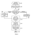
Figure 2 , a flow chart representing illustrative processes for providing access toapplication data 110 in accordance with one aspect of the present disclosure is provided. The processes can begin atblock 200. Atblock 202, theswitching system 106 can receive a call from acalling device 102. An identifier of the calleddevice 104 is provided. The identifier can be the called device's phone number, extension or other attribute describing the calleddevice 104. Other forms of communication can be made by the calling party to give authorisation regardless of whether an actual call is made or not. Theswitching system 106 can determine the name and number information of thecalling device 102. - At
decision block 204, theswitching system 106 can determine whether an access code is provided or a default configuration is used. There can be numerous types of access codes. In some embodiments, the access code can determine whichapplication server 108 to use. The access code can also determine types of privileges given, for example, certain items ofdata 110 can be restricted with varying degrees of access privileges. When no access code is provided, nor default configuration used, theswitching system 106 can interpret this as a regular call whereby theswitching system 106 establishes communication between the callingdevice 102 and the calleddevice 104. - When an access code is provided, at
block 206, theswitching system 106 can determine what type of configuration to use based on the access code provided. For example, the code can be used to grant access to a resume from Monster® to the calleddevice 104. Alternatively, access to the status of the calling party on Facebook® can be provided. Those skilled in the relevant art will appreciate that there are a number of different access codes that can be used with theapplication servers 108 and theapplication data 110 therein. - At
block 208, when no access code has been given, a default configuration can be used. For example, a default configuration can be established where access to a user's resume is always provided. The default configuration can be changed in theswitching system 106 by entering in another access code. - The
switching system 106 can access theapplication server 108 using a calling party number of thecalling device 102 atblock 210. Theapplication server 108 can associate the calling party number toapplication data 110. Theswitching system 106 can add the dialled number associated with the calleddevice 104 to an access list for theapplication data 110 atblock 212. Theswitching system 106 can provide the calleddevice 104 access to theapplication data 110 atblock 214. In addition, name and number information can be provided to the calleddevice 104. The processes for establishing access for the called device to theapplication data 110 can end atblock 216. -
Figure 4A is a block diagram showing an exemplary scenario for providing access toapplication data 110 in accordance with one aspect of the present disclosure. For purposes of illustration, the scenario includes Joe Smith who works at a company that uses a caller profile application. The company has prefilled many of his business settings, for example, position, organisation chart, company name and company phone extension asapplication data 110 within aserver 108. - Joe can access and upload a picture and set his current status within the
application server 108. To update hisapplication data 110, Joe can access a website through a network or in another embodiment, can make a call to theapplication server 108. As shown inFigure 4A , Joe has an account number of 34567 and an extension of 1234. In this scenario, Joe intends to provide access to hisapplication data 110 to Jane Doe at extension 9876. In some embodiments, Joe can chose to dial *759876 whereby *75 is the command to send "Caller Profile" information and 9876 is Jane's extension. The "*" can represent that an access code is being entered. Those skilled in the relevant art will appreciate that there a number of different ways to provide the access code. - When the
switching system 106 is configured to use the application on theapplication server 108 by default, Joe can simply dial 9876. Alternately, if Joe had a smart phone running the Caller Profile client application, the phone can be configured to automatically insert the *75 access code on all calls. Theswitching system 106, upon recognising the *75 feature access code or via configuration settings, can use Joe's calling party number to access his Caller Profile account number. This is done by theswitching system 106 communicating with the CallerProfile application server 108 in some embodiments. Theswitching system 106 can be trusted by theserver 108 thus allowing calling party numbers recognised by the switching system to be queried. - The
switching system 106 can add Jane's number to theaccess control list 402 for Joe's account as shown inFigure 4A . Theaccess list 402 can be maintained within a database that is separate from or attached to theapplication server 108. In some embodiments, theaccess control list 402 can be located on theswitching system 106, or if client applications are used on the calleddevices 104 that communicate directly with theapplication server 108, the interface between the switchingsystem 106 andapplication server 108 can be leveraged to assign theaccess control list 402. By Joe calling Jane, he is granting Jane access to hisapplication data 110. - Once the
access control list 402 has been updated, theswitching system 106 can replace Joe's calling party number such that the information sent to Jane'sdevice 104 is his correct name "Joe Smith". In addition, information regarding access to Joe'sapplication data 110 can be sent, for example, the number *7634567 is provided to Jane's calleddevice 104. *76 can be the command to access "Caller Profile" information and 34567 can refer to Joe's account information. - In some embodiments, the same feature access code provided by Joe can be used. The notion of "send" or "access"
caller profile data 110 can be resolved by a subcode in the calling party number format, or via the number itself. Different access codes can be interleaved to perform different functions. -
Figure 3 is a flow chart representing illustrative processes for accessing theapplication data 110 in accordance with one aspect of the present disclosure. The processes can begin atblock 300. Atblock 302, theswitching system 106 can receive an access request from the calleddevice 104 who earlier received permission to retrieve theapplication data 110. - At
decision block 304, theswitching system 106 can determine whether the called device's number is in theaccess control list 402 that was stored either on theswitching system 106 or theapplication servers 108. When the called device's number is not in theaccess control list 402, the calleddevice 104 is not granted access to theapplication data 110 and the processes can end atblock 308. An error message can be given providing that there was an error in accessing theapplication data 110. - When the number of the called
device 104 is within theaccess control list 402, theswitching system 106 can allow the use of theapplication data 110 atblock 306. The processes can end atblock 308. Theswitching system 106 can be used as an intermediary whereby it can access theapplication servers 108 for thedata 110. As shown inFigure 1 , upon receiving access from the callingdevice 102, the called party can use the granted access to directly communicate with theappropriate application server 108 to retrieve theapplication data 110 associated with the calling party. Alternatively, the called party or calleddevice 104 can access thedata 110 through theswitching system 106. -
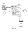
Figure 4B is a block diagram showing exemplary procedures to access theapplication data 110 within the scenario ofFigure 4A in accordance with one aspect of the present disclosure. When access is granted, Jane's calleddevice 104 having the Caller Profile client application can recognise that the *76 as an indication thatadditional data 110 is available via the Caller Profile application. The calleddevice 104 or associated device with the called party can access the Caller Profile application and thereafter, present Joe'sapplication data 110. If Jane's calleddevice 104 does not support the application, Jane can recognise the number prefix and alternatively chose to use her computer or other computing device that was not called to access more information about Joe using this number. Typically the information granting access to Jane would allowseveral devices 104 to access thedata 110. - As shown in
Figure 4B , Jane can have the Caller Profile client application on herpersonal computer 104 that uses CTI to get the calling party number. In some embodiments, Jane can choose to just treat the number as any ordinary number. She can answer the call, or it may be missed, depending on her availability. In some embodiments, Jane can access the data even though the call was missed. - The number provided by the
switching system 106 to Jane is a "routable number". Due to the nature of telephony, typically applications support, at a minimum, resolving a database key to a routable number. The database key can be limited to the calling party number format. In some embodiments, Jane can store this as her contact for Joe or it can be dialled directly from the call log. When Jane dials *7634567, theswitching system 106 can recognise *76 as an indicator of a Caller Profile account number. Theswitching system 106 can use the account number to look up the appropriate profile, and then verify that Jane is allowed to access the profile by checking to see if Jane's extension of 9876 is in theaccess control list 402 for account 34567. - When Jane's extension is within the
access control list 402, theswitching system 106 can access the contact number stored for Joe in his profile, which is 1234. Thereafter, theswitching system 106 can place the call to Joe. In this example the calling party number that Joe sees is 9876 because Jane did not opt to use the *75 feature access code and her client application orswitching system 106 configuration is not set to force the use of the Caller Profile application. In some embodiments, theswitching system 106 can provide reverse number lookup to guarantee that the call can be routed and only provide additional information if theaccess control list 402 is valid. - Turning now to
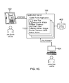
Figure 4C , a block diagram showing exemplary procedures for accessing theapplication data 110 and providing access to theapplication data 110 using the scenario ofFigure 4A in accordance with one aspect of the present disclosure is provided. If Jane had elected to use the Caller Profile feature access code during dialling, her client application would be defaulted to do so. The number received at theswitching system 106 from Jane'sdevice 104 could have been *75*7634567. Theswitching system 106 can resolve *7634567 to Joe's extension 1234, and then replace Jane's calling party number with *7687654. The *76 can be the application code and 87654 can be Jane's account number on theCaller Profile server 108. Joe's number can be added to Jane'saccess control list 402 and similar to before, now Joe can access Jane'sapplication data 110. - Those skilled in the relevant art would appreciate that there can be different variations of the processes described above in a variety of settings. For example, the Caller Profile application can have various data privilege levels. When Jane is Joe's boss, she can have access to special information about him. While Joe is on vacation, Joe can forward calls from his work contact, *761234, to his voicemail since he is not there to answer. However, when the
switching system 106 attempts to route the call from Jane, who has a different privilege level, it can resolve it to Joe's room phone at the resort he is staying. - The permutations and combinations of
server 108 and switchingsystem 106 interactions are plentiful and application dependent. In another scenario, a legal application can be created that allows simplified billing. Generally, calls to and from the legal office utilise database keys referencing customer information. Theswitching system 106 operating on a public switched telephone network (PSTN) can support a Customer Billing application. For example, Bean Lawyers PLLC can subscribe for the service. Their customer number can be 06001. When Bill calls Bean Lawyers at 1-555-555-5555 and requests legal assistance, the secretary can create an account 04011 in their system with Bill's contact information. The secretary can then inform Bill that a lawyer will call him when available. - In turn, the next available lawyer can dial *8804011 whereby *88 activates the billing feature and 04011 references the client. The contact number provided by Bill can be added into the
access control list 402 to allow him to call the lawyer. Thereafter, billing commences for Bill. The calling party number is *880600104011 where *88 activates the feature, 060010 identifies the carrier database instance, Bean Lawyers PLLC, and 04011 resolves to the lawyers the secretary/direct line. Bean Lawyers PLLC can query the account at any time for billing or other information and close the account as required. Bill only knows how to reach the lawyer via the billing number and when he calls the main line again, 1-555-555-5555, the secretary can transfer the call to the account number, which can be resolved to the correct lawyer handling the case at that time. - In another scenario, where Bill decides to change jobs, the
switching system 106 with theapplication servers 108 can be of further use. Bill can call Orange R' Us to provide them access to his resume on LinkedIn®, which is a protected feature and cannot be accessed by general viewers. Currently, Bill would need the email address of the person to whom access is to be granted. - Through the
switching system 106, when Bill calls Orange R' Us, he can automatically grant them permission to view the resume section of his LinkedIn® profile. The format of the calling party number triggers an application at Orange R' Us that a LinkedIn® profile is accessible via the call information. When an employee of Orange R' Us attempts to use the call information to retrieve Bill's profile, the system can authorise the release of this information based on the fact that permission was granted by the telecommunications system during the initial call setup. Any other party who dials the calling party number would be denied. - The foregoing description is provided to enable any person skilled in the relevant art to practice the various embodiments described herein. Various modifications to these embodiments will be readily apparent to those skilled in the relevant art, and generic principles defined herein can be applied to other embodiments. Thus, the claims are not intended to be limited to the embodiments shown and described herein, but are to be accorded the full scope consistent with the language of the claims, wherein reference to an element in the singular is not intended to mean "one and only one" unless specifically stated, but rather "one or more." All structural and functional equivalents to the elements of the various embodiments described throughout this disclosure that are known or later come to be known to those of ordinary skill in the relevant art are intended to be encompassed by the claims. Moreover, nothing disclosed herein is intended to be dedicated to the public regardless of whether such disclosure is explicitly recited in the claims.
Claims (15)
- A method for providing application data comprising:receiving an identifier corresponding to a called party from a calling device,accessing application data of a calling party of said calling device;authorising said called party through said identifier to access to said application data of said calling party;determining an identity of said calling party from said application data; andproviding said identity of said calling party along with authorisation to access said application data to said called party.
- The method of claim 1, wherein accessing said application data of said calling party comprises receiving a code from said calling device and upon recognition of said code, allowing access to said application data.
- The method of claim 1, wherein accessing said application data of said calling party comprises accessing said application data by default, or wherein accessing said application data of said calling party comprises retrieving a number of said calling party to access an application server having said application data.
- The method of any preceding claim, wherein providing said authorisation to said called party comprises presenting a code that allows access to said application data.
- The method of any preceding claim, wherein authorising said called party to access said application data comprises adding said identifier of said called party to an access control list, and optionally comprising receiving a request for said application data by said called party and providing said application data after verifying whether said called party has authorisation, and further optionally wherein verifying whether said called party has authorisation comprises determining whether said identifier of said called party is within said access control list.
- A switch coupled to at least one application having application data, said switch being configured to receive authorisation by a first party for a second party to access application data of said first party from said at least one application, and to provide said authorisation to said second party for said second party to access said application data from said at least one application.
- The system of claim 6, wherein said switch is a private branch exchange.
- The system of claim 6, wherein receiving said authorisation by said first party comprises passing a called party number and an access code and upon recognition of said access code, said switch enabling said authorisation for said second party to access said application data.
- The system of claim 8, wherein enabling said authorisation for said second party to access said application data comprises listing said called party number within an access control list and/or wherein said access code is determined by said switch.
- The system of any of claims 6 to 9, wherein said at least one application comprises at least one client profile for said application data.
- The system of any of claims 6 to 10, wherein said switch receiving authorisation by said first party for said second party to access application data of said first party from said at least one application comprises receiving an access code from said first party.
- The system of any of claims 6 to 11, wherein said switch providing said authorisation to said second party for said second party to access said application data from said at least one application comprises displaying an application on a device of said second party.
- A caller identification system configured to:receive a called party number and an access code from a calling device;identify a called party corresponding to said called party number;authorise said called party to access calling party application data upon recognition of said access code from said calling device;inform said called party of said access to said calling party application data.
- The caller identification system of claim 13, wherein informing said called party of said access to said calling party application data comprises triggering an application on a device of said called party.
- The caller identification system of claim 13 or claim 14, configured to:receive a calling party number and an access code from a called device of said called party;identify a calling party corresponding to said calling party number;authorise said calling party to access called party application data upon recognition of said access code from said called device; andinform said calling party of said access to said called party application data and/or configured to update said calling party application data.
Applications Claiming Priority (1)
| Application Number | Priority Date | Filing Date | Title |
|---|---|---|---|
| US13/065,948 US8537994B2 (en) | 2011-03-31 | 2011-03-31 | System granting access to application data and methods thereof |
Publications (2)
| Publication Number | Publication Date |
|---|---|
| EP2506545A1 true EP2506545A1 (en) | 2012-10-03 |
| EP2506545B1 EP2506545B1 (en) | 2013-12-25 |
Family
ID=45470228
Family Applications (1)
| Application Number | Title | Priority Date | Filing Date |
|---|---|---|---|
| EP11169668.8A Active EP2506545B1 (en) | 2011-03-31 | 2011-06-13 | Authorizing a called party to access a calling party's application data |
Country Status (4)
| Country | Link |
|---|---|
| US (1) | US8537994B2 (en) |
| EP (1) | EP2506545B1 (en) |
| CN (1) | CN102739637A (en) |
| CA (1) | CA2747592C (en) |
Families Citing this family (11)
| Publication number | Priority date | Publication date | Assignee | Title |
|---|---|---|---|---|
| AU2012300387A1 (en) * | 2011-08-26 | 2014-02-27 | Scholastic Inc. | Interactive electronic reader with parental control |
| US9218627B2 (en) * | 2011-12-09 | 2015-12-22 | Facebook, Inc. | Call-termination-triggered social interface |
| US9060057B1 (en) * | 2013-03-07 | 2015-06-16 | Serdar Artun Danis | Systems and methods for caller ID authentication, spoof detection and list based call handling |
| US9332119B1 (en) * | 2013-03-07 | 2016-05-03 | Serdar Artun Danis | Systems and methods for call destination authenticaiton and call forwarding detection |
| WO2015096867A1 (en) * | 2013-12-24 | 2015-07-02 | Telio Nederland B.V. | Callback telecommunication system |
| US9307074B1 (en) * | 2014-03-19 | 2016-04-05 | Alan Ellman | Information transmission device and system |
| US9203954B1 (en) | 2014-07-31 | 2015-12-01 | Ringcentral, Inc. | Enhanced caller-ID information selection and delivery |
| US10003563B2 (en) | 2015-05-26 | 2018-06-19 | Facebook, Inc. | Integrated telephone applications on online social networks |
| US9344892B1 (en) * | 2016-01-19 | 2016-05-17 | Fmr Llc | Mobile device authentication and call routing using dual-tone multi-frequency signaling |
| US11290425B2 (en) * | 2016-02-01 | 2022-03-29 | Airwatch Llc | Configuring network security based on device management characteristics |
| US20220303394A1 (en) * | 2021-03-22 | 2022-09-22 | Avaya Management L.P. | Mapping of telecommunications soft client input to feature access codes of a telecommunications service |
Citations (5)
| Publication number | Priority date | Publication date | Assignee | Title |
|---|---|---|---|---|
| US5864612A (en) * | 1996-10-01 | 1999-01-26 | Bell Atlantic Network Services, Inc. | Caller selective identification for telephone calls |
| EP1211875A2 (en) * | 2000-12-01 | 2002-06-05 | Lucent Technologies Inc. | System and method for delivering profile information relating to a caller |
| US6496571B1 (en) * | 1998-08-28 | 2002-12-17 | Lucent Technologies Inc. | Telecommunication system, method and telephone with personal caller identification capability |
| US20030139172A1 (en) * | 2002-01-23 | 2003-07-24 | Juha Lampela | Rich calling line handling in call setup signalling |
| US20050163298A1 (en) * | 2004-01-22 | 2005-07-28 | International Business Machines Corporation | System and method for providing caller information across heterogeneous networks |
Family Cites Families (7)
| Publication number | Priority date | Publication date | Assignee | Title |
|---|---|---|---|---|
| US5592537A (en) * | 1994-05-20 | 1997-01-07 | Moen; Arthur J. | Method of providing message service for limited access telecommunications |
| US8380630B2 (en) * | 2000-07-06 | 2013-02-19 | David Paul Felsher | Information record infrastructure, system and method |
| US6785368B1 (en) * | 2002-06-24 | 2004-08-31 | Bellsouth Intellectual Property Corporation | On-demand caller identification |
| US7734028B2 (en) * | 2002-09-30 | 2010-06-08 | Avaya Inc. | Method and apparatus for delivering enhanced caller identification services to a called party |
| WO2007064896A2 (en) * | 2005-12-01 | 2007-06-07 | Shahriar Sarkeshik | Data exchange system and method |
| EP2232763A4 (en) * | 2007-12-21 | 2012-08-08 | Cocoon Data Holdings Ltd | SYSTEM AND METHOD FOR SECURING DATA |
| JP5284745B2 (en) * | 2008-10-10 | 2013-09-11 | インターナショナル・ビジネス・マシーンズ・コーポレーション | Apparatus and method for managing access to electronic messages |
-
2011
- 2011-03-31 US US13/065,948 patent/US8537994B2/en active Active
- 2011-06-13 EP EP11169668.8A patent/EP2506545B1/en active Active
- 2011-07-29 CA CA2747592A patent/CA2747592C/en active Active
-
2012
- 2012-03-29 CN CN2012100929678A patent/CN102739637A/en active Pending
Patent Citations (5)
| Publication number | Priority date | Publication date | Assignee | Title |
|---|---|---|---|---|
| US5864612A (en) * | 1996-10-01 | 1999-01-26 | Bell Atlantic Network Services, Inc. | Caller selective identification for telephone calls |
| US6496571B1 (en) * | 1998-08-28 | 2002-12-17 | Lucent Technologies Inc. | Telecommunication system, method and telephone with personal caller identification capability |
| EP1211875A2 (en) * | 2000-12-01 | 2002-06-05 | Lucent Technologies Inc. | System and method for delivering profile information relating to a caller |
| US20030139172A1 (en) * | 2002-01-23 | 2003-07-24 | Juha Lampela | Rich calling line handling in call setup signalling |
| US20050163298A1 (en) * | 2004-01-22 | 2005-07-28 | International Business Machines Corporation | System and method for providing caller information across heterogeneous networks |
Also Published As
| Publication number | Publication date |
|---|---|
| CA2747592C (en) | 2014-02-18 |
| CA2747592A1 (en) | 2012-09-30 |
| CN102739637A (en) | 2012-10-17 |
| US8537994B2 (en) | 2013-09-17 |
| EP2506545B1 (en) | 2013-12-25 |
| US20120250845A1 (en) | 2012-10-04 |
Similar Documents
| Publication | Publication Date | Title |
|---|---|---|
| EP2506545B1 (en) | Authorizing a called party to access a calling party's application data | |
| US9225829B2 (en) | Method and system for providing communication party related information | |
| US20200128366A1 (en) | System and method for provision of a second line service on mobile telephone | |
| EP1511284B1 (en) | System and method for enhanced computer telephony integration and interaction | |
| US20120220279A1 (en) | Updating contact information for mobile traffic | |
| US9979827B2 (en) | Telecommunications device enabled with multiple network recognizable numbers | |
| US11082548B2 (en) | System and method for providing a pre-populated second line service to a telecommunications device | |
| US12452362B2 (en) | Automatic caller identification translation | |
| CN1650604A (en) | System and a method for connecting telephone calls directly on the basis of a text query | |
| CN102438088A (en) | Internet telephone method in a plurality of social identity environments | |
| CN100444693C (en) | A method of accessing a mobile communication device | |
| CN101400056B (en) | Highly secured portable telephone system and information system | |
| CN102664818B (en) | For the terminal, the method and system that communicate | |
| JP2010109507A (en) | Method and apparatus for storing extension of cellular phone | |
| US11595791B2 (en) | System and method for provision of dial-requested service to a second line service enabled telecommunications device | |
| KR20070035151A (en) | How to provide caller / caller nickname display service in connection with user address book | |
| KR20020088336A (en) | Method and system of information service for user using public database |
Legal Events
| Date | Code | Title | Description |
|---|---|---|---|
| PUAI | Public reference made under article 153(3) epc to a published international application that has entered the european phase |
Free format text: ORIGINAL CODE: 0009012 |
|
| AK | Designated contracting states |
Kind code of ref document: A1 Designated state(s): AL AT BE BG CH CY CZ DE DK EE ES FI FR GB GR HR HU IE IS IT LI LT LU LV MC MK MT NL NO PL PT RO RS SE SI SK SM TR |
|
| AX | Request for extension of the european patent |
Extension state: BA ME |
|
| 17P | Request for examination filed |
Effective date: 20130221 |
|
| GRAP | Despatch of communication of intention to grant a patent |
Free format text: ORIGINAL CODE: EPIDOSNIGR1 |
|
| RIC1 | Information provided on ipc code assigned before grant |
Ipc: H04M 3/42 20060101AFI20130604BHEP Ipc: H04M 3/436 20060101ALI20130604BHEP Ipc: H04M 7/00 20060101ALI20130604BHEP |
|
| INTG | Intention to grant announced |
Effective date: 20130704 |
|
| GRAS | Grant fee paid |
Free format text: ORIGINAL CODE: EPIDOSNIGR3 |
|
| GRAA | (expected) grant |
Free format text: ORIGINAL CODE: 0009210 |
|
| AK | Designated contracting states |
Kind code of ref document: B1 Designated state(s): AL AT BE BG CH CY CZ DE DK EE ES FI FR GB GR HR HU IE IS IT LI LT LU LV MC MK MT NL NO PL PT RO RS SE SI SK SM TR |
|
| REG | Reference to a national code |
Ref country code: GB Ref legal event code: FG4D |
|
| REG | Reference to a national code |
Ref country code: CH Ref legal event code: EP |
|
| REG | Reference to a national code |
Ref country code: AT Ref legal event code: REF Ref document number: 647110 Country of ref document: AT Kind code of ref document: T Effective date: 20140115 |
|
| REG | Reference to a national code |
Ref country code: IE Ref legal event code: FG4D |
|
| REG | Reference to a national code |
Ref country code: DE Ref legal event code: R096 Ref document number: 602011004309 Country of ref document: DE Effective date: 20140213 |
|
| PG25 | Lapsed in a contracting state [announced via postgrant information from national office to epo] |
Ref country code: NO Free format text: LAPSE BECAUSE OF FAILURE TO SUBMIT A TRANSLATION OF THE DESCRIPTION OR TO PAY THE FEE WITHIN THE PRESCRIBED TIME-LIMIT Effective date: 20140325 Ref country code: FI Free format text: LAPSE BECAUSE OF FAILURE TO SUBMIT A TRANSLATION OF THE DESCRIPTION OR TO PAY THE FEE WITHIN THE PRESCRIBED TIME-LIMIT Effective date: 20131225 Ref country code: SE Free format text: LAPSE BECAUSE OF FAILURE TO SUBMIT A TRANSLATION OF THE DESCRIPTION OR TO PAY THE FEE WITHIN THE PRESCRIBED TIME-LIMIT Effective date: 20131225 Ref country code: LT Free format text: LAPSE BECAUSE OF FAILURE TO SUBMIT A TRANSLATION OF THE DESCRIPTION OR TO PAY THE FEE WITHIN THE PRESCRIBED TIME-LIMIT Effective date: 20131225 Ref country code: HR Free format text: LAPSE BECAUSE OF FAILURE TO SUBMIT A TRANSLATION OF THE DESCRIPTION OR TO PAY THE FEE WITHIN THE PRESCRIBED TIME-LIMIT Effective date: 20131225 |
|
| REG | Reference to a national code |
Ref country code: NL Ref legal event code: VDEP Effective date: 20131225 |
|
| REG | Reference to a national code |
Ref country code: AT Ref legal event code: MK05 Ref document number: 647110 Country of ref document: AT Kind code of ref document: T Effective date: 20131225 |
|
| REG | Reference to a national code |
Ref country code: LT Ref legal event code: MG4D |
|
| PG25 | Lapsed in a contracting state [announced via postgrant information from national office to epo] |
Ref country code: LV Free format text: LAPSE BECAUSE OF FAILURE TO SUBMIT A TRANSLATION OF THE DESCRIPTION OR TO PAY THE FEE WITHIN THE PRESCRIBED TIME-LIMIT Effective date: 20131225 Ref country code: RS Free format text: LAPSE BECAUSE OF FAILURE TO SUBMIT A TRANSLATION OF THE DESCRIPTION OR TO PAY THE FEE WITHIN THE PRESCRIBED TIME-LIMIT Effective date: 20131225 |
|
| PG25 | Lapsed in a contracting state [announced via postgrant information from national office to epo] |
Ref country code: EE Free format text: LAPSE BECAUSE OF FAILURE TO SUBMIT A TRANSLATION OF THE DESCRIPTION OR TO PAY THE FEE WITHIN THE PRESCRIBED TIME-LIMIT Effective date: 20131225 Ref country code: BE Free format text: LAPSE BECAUSE OF FAILURE TO SUBMIT A TRANSLATION OF THE DESCRIPTION OR TO PAY THE FEE WITHIN THE PRESCRIBED TIME-LIMIT Effective date: 20131225 Ref country code: IS Free format text: LAPSE BECAUSE OF FAILURE TO SUBMIT A TRANSLATION OF THE DESCRIPTION OR TO PAY THE FEE WITHIN THE PRESCRIBED TIME-LIMIT Effective date: 20140425 |
|
| PG25 | Lapsed in a contracting state [announced via postgrant information from national office to epo] |
Ref country code: CY Free format text: LAPSE BECAUSE OF FAILURE TO SUBMIT A TRANSLATION OF THE DESCRIPTION OR TO PAY THE FEE WITHIN THE PRESCRIBED TIME-LIMIT Effective date: 20131225 Ref country code: CZ Free format text: LAPSE BECAUSE OF FAILURE TO SUBMIT A TRANSLATION OF THE DESCRIPTION OR TO PAY THE FEE WITHIN THE PRESCRIBED TIME-LIMIT Effective date: 20131225 Ref country code: AT Free format text: LAPSE BECAUSE OF FAILURE TO SUBMIT A TRANSLATION OF THE DESCRIPTION OR TO PAY THE FEE WITHIN THE PRESCRIBED TIME-LIMIT Effective date: 20131225 Ref country code: SK Free format text: LAPSE BECAUSE OF FAILURE TO SUBMIT A TRANSLATION OF THE DESCRIPTION OR TO PAY THE FEE WITHIN THE PRESCRIBED TIME-LIMIT Effective date: 20131225 Ref country code: NL Free format text: LAPSE BECAUSE OF FAILURE TO SUBMIT A TRANSLATION OF THE DESCRIPTION OR TO PAY THE FEE WITHIN THE PRESCRIBED TIME-LIMIT Effective date: 20131225 Ref country code: ES Free format text: LAPSE BECAUSE OF FAILURE TO SUBMIT A TRANSLATION OF THE DESCRIPTION OR TO PAY THE FEE WITHIN THE PRESCRIBED TIME-LIMIT Effective date: 20131225 Ref country code: PT Free format text: LAPSE BECAUSE OF FAILURE TO SUBMIT A TRANSLATION OF THE DESCRIPTION OR TO PAY THE FEE WITHIN THE PRESCRIBED TIME-LIMIT Effective date: 20140428 Ref country code: RO Free format text: LAPSE BECAUSE OF FAILURE TO SUBMIT A TRANSLATION OF THE DESCRIPTION OR TO PAY THE FEE WITHIN THE PRESCRIBED TIME-LIMIT Effective date: 20131225 |
|
| REG | Reference to a national code |
Ref country code: DE Ref legal event code: R097 Ref document number: 602011004309 Country of ref document: DE |
|
| PG25 | Lapsed in a contracting state [announced via postgrant information from national office to epo] |
Ref country code: DK Free format text: LAPSE BECAUSE OF FAILURE TO SUBMIT A TRANSLATION OF THE DESCRIPTION OR TO PAY THE FEE WITHIN THE PRESCRIBED TIME-LIMIT Effective date: 20131225 |
|
| PLBE | No opposition filed within time limit |
Free format text: ORIGINAL CODE: 0009261 |
|
| STAA | Information on the status of an ep patent application or granted ep patent |
Free format text: STATUS: NO OPPOSITION FILED WITHIN TIME LIMIT |
|
| PG25 | Lapsed in a contracting state [announced via postgrant information from national office to epo] |
Ref country code: PL Free format text: LAPSE BECAUSE OF FAILURE TO SUBMIT A TRANSLATION OF THE DESCRIPTION OR TO PAY THE FEE WITHIN THE PRESCRIBED TIME-LIMIT Effective date: 20131225 |
|
| 26N | No opposition filed |
Effective date: 20140926 |
|
| REG | Reference to a national code |
Ref country code: DE Ref legal event code: R097 Ref document number: 602011004309 Country of ref document: DE Effective date: 20140926 |
|
| PG25 | Lapsed in a contracting state [announced via postgrant information from national office to epo] |
Ref country code: LU Free format text: LAPSE BECAUSE OF FAILURE TO SUBMIT A TRANSLATION OF THE DESCRIPTION OR TO PAY THE FEE WITHIN THE PRESCRIBED TIME-LIMIT Effective date: 20140613 Ref country code: MC Free format text: LAPSE BECAUSE OF FAILURE TO SUBMIT A TRANSLATION OF THE DESCRIPTION OR TO PAY THE FEE WITHIN THE PRESCRIBED TIME-LIMIT Effective date: 20131225 |
|
| REG | Reference to a national code |
Ref country code: CH Ref legal event code: PL |
|
| REG | Reference to a national code |
Ref country code: IE Ref legal event code: MM4A |
|
| REG | Reference to a national code |
Ref country code: FR Ref legal event code: ST Effective date: 20150227 |
|
| PG25 | Lapsed in a contracting state [announced via postgrant information from national office to epo] |
Ref country code: CH Free format text: LAPSE BECAUSE OF NON-PAYMENT OF DUE FEES Effective date: 20140630 Ref country code: LI Free format text: LAPSE BECAUSE OF NON-PAYMENT OF DUE FEES Effective date: 20140630 Ref country code: IE Free format text: LAPSE BECAUSE OF NON-PAYMENT OF DUE FEES Effective date: 20140613 |
|
| PG25 | Lapsed in a contracting state [announced via postgrant information from national office to epo] |
Ref country code: FR Free format text: LAPSE BECAUSE OF NON-PAYMENT OF DUE FEES Effective date: 20140630 Ref country code: SI Free format text: LAPSE BECAUSE OF FAILURE TO SUBMIT A TRANSLATION OF THE DESCRIPTION OR TO PAY THE FEE WITHIN THE PRESCRIBED TIME-LIMIT Effective date: 20131225 |
|
| PG25 | Lapsed in a contracting state [announced via postgrant information from national office to epo] |
Ref country code: MT Free format text: LAPSE BECAUSE OF FAILURE TO SUBMIT A TRANSLATION OF THE DESCRIPTION OR TO PAY THE FEE WITHIN THE PRESCRIBED TIME-LIMIT Effective date: 20131225 |
|
| PG25 | Lapsed in a contracting state [announced via postgrant information from national office to epo] |
Ref country code: SM Free format text: LAPSE BECAUSE OF FAILURE TO SUBMIT A TRANSLATION OF THE DESCRIPTION OR TO PAY THE FEE WITHIN THE PRESCRIBED TIME-LIMIT Effective date: 20131225 |
|
| PG25 | Lapsed in a contracting state [announced via postgrant information from national office to epo] |
Ref country code: GR Free format text: LAPSE BECAUSE OF FAILURE TO SUBMIT A TRANSLATION OF THE DESCRIPTION OR TO PAY THE FEE WITHIN THE PRESCRIBED TIME-LIMIT Effective date: 20140326 Ref country code: IT Free format text: LAPSE BECAUSE OF FAILURE TO SUBMIT A TRANSLATION OF THE DESCRIPTION OR TO PAY THE FEE WITHIN THE PRESCRIBED TIME-LIMIT Effective date: 20131225 Ref country code: BG Free format text: LAPSE BECAUSE OF FAILURE TO SUBMIT A TRANSLATION OF THE DESCRIPTION OR TO PAY THE FEE WITHIN THE PRESCRIBED TIME-LIMIT Effective date: 20131225 |
|
| PG25 | Lapsed in a contracting state [announced via postgrant information from national office to epo] |
Ref country code: HU Free format text: LAPSE BECAUSE OF FAILURE TO SUBMIT A TRANSLATION OF THE DESCRIPTION OR TO PAY THE FEE WITHIN THE PRESCRIBED TIME-LIMIT; INVALID AB INITIO Effective date: 20110613 Ref country code: TR Free format text: LAPSE BECAUSE OF FAILURE TO SUBMIT A TRANSLATION OF THE DESCRIPTION OR TO PAY THE FEE WITHIN THE PRESCRIBED TIME-LIMIT Effective date: 20131225 |
|
| PG25 | Lapsed in a contracting state [announced via postgrant information from national office to epo] |
Ref country code: MK Free format text: LAPSE BECAUSE OF FAILURE TO SUBMIT A TRANSLATION OF THE DESCRIPTION OR TO PAY THE FEE WITHIN THE PRESCRIBED TIME-LIMIT Effective date: 20131225 |
|
| PG25 | Lapsed in a contracting state [announced via postgrant information from national office to epo] |
Ref country code: AL Free format text: LAPSE BECAUSE OF FAILURE TO SUBMIT A TRANSLATION OF THE DESCRIPTION OR TO PAY THE FEE WITHIN THE PRESCRIBED TIME-LIMIT Effective date: 20131225 |
|
| REG | Reference to a national code |
Ref country code: DE Ref legal event code: R082 Ref document number: 602011004309 Country of ref document: DE Representative=s name: VENNER SHIPLEY GERMANY LLP, DE Ref country code: DE Ref legal event code: R082 Ref document number: 602011004309 Country of ref document: DE Representative=s name: VENNER SHIPLEY LLP, DE |
|
| PGFP | Annual fee paid to national office [announced via postgrant information from national office to epo] |
Ref country code: DE Payment date: 20250402 Year of fee payment: 15 |
|
| PGFP | Annual fee paid to national office [announced via postgrant information from national office to epo] |
Ref country code: GB Payment date: 20250401 Year of fee payment: 15 |