EP2506446A1 - Apparatus, systems and methods for power line carrier data communication to DC powered electronic device - Google Patents
Apparatus, systems and methods for power line carrier data communication to DC powered electronic device Download PDFInfo
- Publication number
- EP2506446A1 EP2506446A1 EP12159675A EP12159675A EP2506446A1 EP 2506446 A1 EP2506446 A1 EP 2506446A1 EP 12159675 A EP12159675 A EP 12159675A EP 12159675 A EP12159675 A EP 12159675A EP 2506446 A1 EP2506446 A1 EP 2506446A1
- Authority
- EP
- European Patent Office
- Prior art keywords
- power
- information
- information signal
- electronic device
- powered electronic
- Prior art date
- Legal status (The legal status is an assumption and is not a legal conclusion. Google has not performed a legal analysis and makes no representation as to the accuracy of the status listed.)
- Granted
Links
Images


Classifications
-
- H—ELECTRICITY
- H04—ELECTRIC COMMUNICATION TECHNIQUE
- H04B—TRANSMISSION
- H04B3/00—Line transmission systems
- H04B3/54—Systems for transmission via power distribution lines
-
- G—PHYSICS
- G08—SIGNALLING
- G08C—TRANSMISSION SYSTEMS FOR MEASURED VALUES, CONTROL OR SIMILAR SIGNALS
- G08C19/00—Electric signal transmission systems
-
- H—ELECTRICITY
- H02—GENERATION; CONVERSION OR DISTRIBUTION OF ELECTRIC POWER
- H02J—ELECTRIC POWER NETWORKS; CIRCUIT ARRANGEMENTS OR SYSTEMS FOR SUPPLYING OR DISTRIBUTING ELECTRIC POWER; SYSTEMS FOR STORING ELECTRIC ENERGY
- H02J13/00—Circuit arrangements for providing remote monitoring or remote control of equipment in a power distribution network
- H02J13/13—Circuit arrangements for providing remote monitoring or remote control of equipment in a power distribution network characterised by the transmission of data to equipment in the power network
- H02J13/1311—Circuit arrangements for providing remote monitoring or remote control of equipment in a power distribution network characterised by the transmission of data to equipment in the power network using the power network as support for the transmission
- H02J13/1315—Circuit arrangements for providing remote monitoring or remote control of equipment in a power distribution network characterised by the transmission of data to equipment in the power network using the power network as support for the transmission using modification of a parameter of the network power signal
-
- H—ELECTRICITY
- H02—GENERATION; CONVERSION OR DISTRIBUTION OF ELECTRIC POWER
- H02J—ELECTRIC POWER NETWORKS; CIRCUIT ARRANGEMENTS OR SYSTEMS FOR SUPPLYING OR DISTRIBUTING ELECTRIC POWER; SYSTEMS FOR STORING ELECTRIC ENERGY
- H02J13/00—Circuit arrangements for providing remote monitoring or remote control of equipment in a power distribution network
- H02J13/13—Circuit arrangements for providing remote monitoring or remote control of equipment in a power distribution network characterised by the transmission of data to equipment in the power network
- H02J13/1321—Circuit arrangements for providing remote monitoring or remote control of equipment in a power distribution network characterised by the transmission of data to equipment in the power network using a wired telecommunication network or a data transmission bus
- H02J13/1323—Circuit arrangements for providing remote monitoring or remote control of equipment in a power distribution network characterised by the transmission of data to equipment in the power network using a wired telecommunication network or a data transmission bus using optical fibres
-
- H—ELECTRICITY
- H04—ELECTRIC COMMUNICATION TECHNIQUE
- H04B—TRANSMISSION
- H04B2203/00—Indexing scheme relating to line transmission systems
- H04B2203/54—Aspects of powerline communications not already covered by H04B3/54 and its subgroups
- H04B2203/5462—Systems for power line communications
- H04B2203/547—Systems for power line communications via DC power distribution
-
- Y—GENERAL TAGGING OF NEW TECHNOLOGICAL DEVELOPMENTS; GENERAL TAGGING OF CROSS-SECTIONAL TECHNOLOGIES SPANNING OVER SEVERAL SECTIONS OF THE IPC; TECHNICAL SUBJECTS COVERED BY FORMER USPC CROSS-REFERENCE ART COLLECTIONS [XRACs] AND DIGESTS
- Y02—TECHNOLOGIES OR APPLICATIONS FOR MITIGATION OR ADAPTATION AGAINST CLIMATE CHANGE
- Y02E—REDUCTION OF GREENHOUSE GAS [GHG] EMISSIONS, RELATED TO ENERGY GENERATION, TRANSMISSION OR DISTRIBUTION
- Y02E60/00—Enabling technologies; Technologies with a potential or indirect contribution to GHG emissions mitigation
-
- Y—GENERAL TAGGING OF NEW TECHNOLOGICAL DEVELOPMENTS; GENERAL TAGGING OF CROSS-SECTIONAL TECHNOLOGIES SPANNING OVER SEVERAL SECTIONS OF THE IPC; TECHNICAL SUBJECTS COVERED BY FORMER USPC CROSS-REFERENCE ART COLLECTIONS [XRACs] AND DIGESTS
- Y04—INFORMATION OR COMMUNICATION TECHNOLOGIES HAVING AN IMPACT ON OTHER TECHNOLOGY AREAS
- Y04S—SYSTEMS INTEGRATING TECHNOLOGIES RELATED TO POWER NETWORK OPERATION, COMMUNICATION OR INFORMATION TECHNOLOGIES FOR IMPROVING THE ELECTRICAL POWER GENERATION, TRANSMISSION, DISTRIBUTION, MANAGEMENT OR USAGE, i.e. SMART GRIDS
- Y04S10/00—Systems supporting electrical power generation, transmission or distribution
- Y04S10/50—Systems or methods supporting the power network operation or management, involving a certain degree of interaction with the load-side end user applications
- Y04S10/52—Outage or fault management, e.g. fault detection or location
-
- Y—GENERAL TAGGING OF NEW TECHNOLOGICAL DEVELOPMENTS; GENERAL TAGGING OF CROSS-SECTIONAL TECHNOLOGIES SPANNING OVER SEVERAL SECTIONS OF THE IPC; TECHNICAL SUBJECTS COVERED BY FORMER USPC CROSS-REFERENCE ART COLLECTIONS [XRACs] AND DIGESTS
- Y04—INFORMATION OR COMMUNICATION TECHNOLOGIES HAVING AN IMPACT ON OTHER TECHNOLOGY AREAS
- Y04S—SYSTEMS INTEGRATING TECHNOLOGIES RELATED TO POWER NETWORK OPERATION, COMMUNICATION OR INFORMATION TECHNOLOGIES FOR IMPROVING THE ELECTRICAL POWER GENERATION, TRANSMISSION, DISTRIBUTION, MANAGEMENT OR USAGE, i.e. SMART GRIDS
- Y04S40/00—Systems for electrical power generation, transmission, distribution or end-user application management characterised by the use of communication or information technologies, or communication or information technology specific aspects supporting them
- Y04S40/12—Systems for electrical power generation, transmission, distribution or end-user application management characterised by the use of communication or information technologies, or communication or information technology specific aspects supporting them characterised by data transport means between the monitoring, controlling or managing units and monitored, controlled or operated electrical equipment
- Y04S40/121—Systems for electrical power generation, transmission, distribution or end-user application management characterised by the use of communication or information technologies, or communication or information technology specific aspects supporting them characterised by data transport means between the monitoring, controlling or managing units and monitored, controlled or operated electrical equipment using the power network as support for the transmission
-
- Y—GENERAL TAGGING OF NEW TECHNOLOGICAL DEVELOPMENTS; GENERAL TAGGING OF CROSS-SECTIONAL TECHNOLOGIES SPANNING OVER SEVERAL SECTIONS OF THE IPC; TECHNICAL SUBJECTS COVERED BY FORMER USPC CROSS-REFERENCE ART COLLECTIONS [XRACs] AND DIGESTS
- Y04—INFORMATION OR COMMUNICATION TECHNOLOGIES HAVING AN IMPACT ON OTHER TECHNOLOGY AREAS
- Y04S—SYSTEMS INTEGRATING TECHNOLOGIES RELATED TO POWER NETWORK OPERATION, COMMUNICATION OR INFORMATION TECHNOLOGIES FOR IMPROVING THE ELECTRICAL POWER GENERATION, TRANSMISSION, DISTRIBUTION, MANAGEMENT OR USAGE, i.e. SMART GRIDS
- Y04S40/00—Systems for electrical power generation, transmission, distribution or end-user application management characterised by the use of communication or information technologies, or communication or information technology specific aspects supporting them
- Y04S40/12—Systems for electrical power generation, transmission, distribution or end-user application management characterised by the use of communication or information technologies, or communication or information technology specific aspects supporting them characterised by data transport means between the monitoring, controlling or managing units and monitored, controlled or operated electrical equipment
- Y04S40/124—Systems for electrical power generation, transmission, distribution or end-user application management characterised by the use of communication or information technologies, or communication or information technology specific aspects supporting them characterised by data transport means between the monitoring, controlling or managing units and monitored, controlled or operated electrical equipment using wired telecommunication networks or data transmission busses
Definitions
- Media devices such as a set top box, a stereo, a television, a computer system, a game system, or the like are configured to receive media content.
- the media content may be received at the media device from a variety of sources.
- the media device may be communicatively coupled to a media content provider system, such as a satellite system, a cable system, a fiber optic system, an over the air (OTA) system, and/or the Internet.
- OTA over the air
- the received media content is communicated to a presentation device having a display and/or speakers.
- the video portion of the media content is presented on the display and the audio portion of the media content is reproduced as sounds by the speakers.
- Power for operation of the media device is provided by an alternating current (AC) power supply that is transmitted through the customer premises by a power wiring network.
- the customer premises AC power wiring network includes a plurality of power receptacles distributed across the customer premises at convenient locations. A connector with a mating plug is coupled to the power receptacle to receive the AC power.
- data may be communicated from the media device to other client electronic client media devices by modulating data onto the customer premises AC power wiring network, commonly known as communicating data over a power line carrier network.
- the electronic client media device which is also "plugged into” the customer premises AC power wiring network for its power, detects and demodulates the communicated power line carrier data communicated on the voltage of the AC power delivered by the customer premises AC power wiring network. The communicated data may then be used for a variety of purposes.
- the electronic client media device may also communicate data back to the media device, or may communicate data destined for other electronic client media devices, by modulating the return data onto AC voltage of the AC power wiring network.
- Other types of electronic devices located at the customer premises may also communicate over the customer premises AC power wiring network.
- a variety of home appliances may communicate with each other using the customer premises AC power wiring network, where the AC voltage on the AC power wiring network is used as a data carrier upon which the communicated data is modulated thereon.
- a demodulator device located at the power receptacle of the AC power wiring network is required to detect and demodulate the communicated data detected on the voltage of the AC power.
- the communicated data is then provided from the demodulator to the various components of the client media device or home appliance via a separate data line, such as a universal serial bus (USB) cable, an Ethernet connector, or the like.
- USB universal serial bus
- the separate data line and its associated components may constitute a significant cost. Accordingly, there is a need in the arts to further reduce costs by eliminating the need for the separate data line.
- An exemplary embodiment receives alternating current (AC) power with an AC information signal modulated thereon, converts the received AC power to DC power, demodulates the received AC information signal to determine information, modulates the information onto the transmitted DC power as a DC information signal, transmits the DC power with the DC information signal over a DC connector to the DC powered electronic device, detects the DC information signal on the modulated DC power at the DC powered electronic device, demodulates the DC information signal from the received DC power, and determines the information at the DC powered electronic device based upon the demodulated DC information.
- AC alternating current
- detecting the DC information signal on the modulated DC power comprises detecting the DC information signal on the modulated DC power at a DC power bus of the DC powered electronic device.
- the method further comprises transmitting the information onto a data bus, wherein at least one component of the DC powered electronic device receives the transmitted information.
- the method may preferably further comprise operating at least one component of the DC powered electronic device in accordance with the determined information.
- Modulating the DC information onto the transmitted DC power as the DC information signal preferably comprises: outputting the DC power at a first voltage, wherein the first voltage corresponds to a first bit; and outputting the DC power at a second voltage, wherein the second voltage corresponds to a second bit, wherein the information signal corresponds to a series of the first voltage and the second voltage.
- modulating the DC information onto the transmitted DC power as the DC information signal may comprise: modulating an AC signal onto the DC power onto the transmitted DC power, wherein a first frequency shift in the AC signal corresponds to a first bit, wherein a second frequency shift in the AC signal corresponds to a second bit, and wherein the information corresponds to a series of the first frequency shift and the second frequency shift.
- the DC information signal may be a first DC information signal having first information modulated thereon, and the method may then preferably further comprise: modulating second information onto the received DC power as a second DC information signal; receiving the DC power with the second DC information signal modulated thereon; demodulating the second DC information signal to determine the second information; and modulating the information onto the AC power as a second AC information signal modulated thereon.
- the second DC information signal may be detectable at a power receptacle of a customer premises AC power wiring network, and the method may preferably further comprises detecting the second DC information signal at the receptacle. Detecting the second DC information signal at the receptacle may comprise detecting the second DC information signal at a host device that originated the first DC information signal.
- the DC powered electronic device may be a first DC powered electronic device, and detecting the second DC information signal at the receptacle may then comprise detecting the second DC information signal at a second DC powered electronic device.
- the method further comprises: determining an identifier in the demodulated information; and comparing the identifier with a device identifier associated with the DC powered electronic device, wherein at least one of the demodulating of the received AC information signal and the modulating of the information onto the transmitted DC power as a DC information signal is performed when the identifier corresponds to the device identifier associated with the DC powered electronic device.
- Determining the information at the DC powered electronic device based upon the demodulated DC information may further comprise: determining an identifier in the demodulated information; comparing the identifier with a device identifier associated with the DC powered electronic device; and operating at least one component of the DC powered electronic device in accordance with the determined information when the identifier corresponds to the device identifier associated with the DC powered electronic device.
- Embodiments of the invention may provide a direct current (DC) powered electronic system configured to receive alternating current (AC) power from an AC power wiring network.
- the system comprises: a DC connector configured to transmit DC power; and a receptacle connector electrically coupled to the DC connector, and configured to electrically couple to a receptacle of the AC power wiring network, wherein the AC power includes an AC information signal modulated thereon.
- the receptacle connector comprises: an AC/DC power converter configured to receive the AC power from the AC power wiring network, configured to convert the AC power into the DC power, and configured to transmit the DC power onto the DC connector; an AC modulator/demodulator configured to detect the AC information signal, and configured to demodulate the AC information signal to determine information; and a DC modulator/demodulator coupled to the AC modulator/demodulator, configured to modulate the information into a DC information signal onto the DC power transmitted from the AC/DC power converter.
- an AC/DC power converter configured to receive the AC power from the AC power wiring network, configured to convert the AC power into the DC power, and configured to transmit the DC power onto the DC connector
- an AC modulator/demodulator configured to detect the AC information signal, and configured to demodulate the AC information signal to determine information
- a DC modulator/demodulator coupled to the AC modulator/demodulator, configured to modulate the information into a DC information signal onto the DC power transmitted from the AC/DC power converter.
- the system further comprises a DC powered electronic device coupled to the DC connector, wherein the received DC power received from the receptacle connector over the DC connector powers at least first one component of the DC powered electronic device, and wherein the information modulated into the DC information signal is demodulated into the information, and wherein the information is received by at least one second component of the DC powered electronic device.
- the receptacle connector further comprises a central processor unit (CPU) configured to determine an identifier in the demodulated information, wherein the CPU is configured to operate at least one of the AC modulator/demodulator and the DC modulator/demodulator so that the information is modulated into the DC information signal when the identifier corresponds to a device identifier associated with the DC powered electronic device.
- CPU central processor unit
- the DC modulator/demodulator of the receptacle connector may be a first DC modulator/demodulator, wherein the DC powered electronic device further comprises: a second DC modulator/demodulator configured to detect the DC information signal modulated onto the DC power received from the receptacle connector over the DC connector, and configured to demodulate the information from the DC information signal.
- the DC powered electronic device further comprises: a data bus communicatively coupled to the second DC modulator/demodulator and the second component, wherein the data bus is configured to receive the information from the second DC modulator/demodulator, and wherein the information is received by the at least one second component over the data bus.
- the system may further comprise: a DC power bus coupled to the DC connector, and configured to receive the DC power, wherein the DC power is received by the at least one first component from the DC power bus.
- Embodiments of the invention may further provide a direct current (DC) powered electronic device configured to operate on received direct current (DC) power based upon alternating current (AC) power received from an AC power wiring network.
- the device comprises a DC power bus configured to electrically couple to a DC connector and configured to receive DC power over the DC connector, wherein the DC connector is electrically coupled to a receptacle connector, and wherein the receptacle connector is configured to couple to a receptacle of the AC power wiring network.
- the device further comprises a DC modulator/demodulator coupled to at least one of a DC connector and an AC modulator/demodulator, wherein the DC modulator/demodulator is configured to demodulate information from a DC information signal modulated onto the DC power.
- a data bus is provided that is communicatively coupled to the DC modulator/demodulator and configured to receive the information demodulated from the DC information signal.
- At least one component is communicatively coupled to the data bus, wherein the information is configured to operate the at least one component, wherein the information is received by the at least one component from the data bus, and wherein DC power to operate the at least one component is received from the DC power bus.
- the device may preferably further comprise a processor system configured to determine an identifier included in the information demodulated from the DC information signal, configured to compare the identifier with a device identifier associated with the DC powered electronic device, and configured to operate the at least one component when the identifier corresponds to the device identifier.
- a processor system configured to determine an identifier included in the information demodulated from the DC information signal, configured to compare the identifier with a device identifier associated with the DC powered electronic device, and configured to operate the at least one component when the identifier corresponds to the device identifier.
- FIGURE 1 is a block diagram of an embodiment of a direct current (DC) data communication system 100 implemented at a customer premises;
- DC direct current
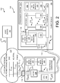
- FIGURE 2 is a block diagram of an embodiment of client device and its respective receptacle connector
- FIGURE 3 is a block diagram of an exemplary host media device and an exemplary client media device.
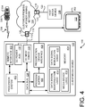
- FIGURE 4 is a block diagram of an exemplary client media device.
- FIGURE 1 is a block diagram of an embodiment of a direct current (DC) data communication system 100 implemented at a customer premises 102.
- the DC data communication system 100 is configured to communicate data over the customer premises alternating current (AC) power wiring network 104.
- a host device 106 may communicate data to/from one or more DC powered electronic devices 108, hereinafter client devices 108, via the customer premises AC power wiring network 104, and via a DC connector 110 that couples the client device 108 to the customer premises AC power wiring network 104. Further, the client devices 108 may communicate with each other over their respective DC connectors 110 and the customer premises AC power wiring network 104.
- the client devices 108 are configured to operate on DC power.
- the DC power is provided from the customer premises AC power wiring network 104 after a conversion of AC power into DC power.
- the DC power is transmitted to the DC powered electronic client devices 108 over the DC connectors 110.
- the customer premises 102 corresponds to a location under the control of a customer, such as a residence, office, or other customer facility.
- the customer premises AC power wiring network 104 comprises a network of conductors suitable for distribution of power throughout the customer premises 102.
- the distributed AC power is received from a power supplier that provides the power from an AC distribution system (not shown).
- the AC distribution system employs a relatively high distribution AC voltage.
- a transformer (not shown) steps the higher distribution voltage down to a lower AC voltage that is provided to the customer premises AC power wiring network 104.
- the lower AC voltage is an operating voltage that various equipment located at the customer premises 102 have been designed to operate at. For example, 120 volt AC power may be received from the transformer for distribution across the customer premises AC power wiring network 104.
- the exemplary customer premises AC power wiring network 104 comprises a phase conductor 112, a neutral conductor 114, and a ground conductor 116 that cooperatively distribute the 120 volt AC power.
- Other configurations and/or voltages, such as 240 volts, may be used for other types of customer premises AC power wiring networks 104.
- a plurality of power receptacles 118, coupled to the customer premises AC power wiring network 104, are distributed throughout the customer premises 102 to provide convenient access to various electronic devices that are to be sourced from the 120 volt AC power provided by the customer premises AC power wiring network 104.
- a host device 106 may have an AC power connector 120 with a mating plug 122. When the mating plug 122 is coupled to one of the power receptacles 118, the host device 106 will receive 120 volt AC power from the customer premises AC power wiring network 104.
- the host device 106 modulates an AC information signal 124 onto the AC voltage on the customer premises AC power wiring network 104.
- the AC information signal 124 is detectable at the plurality of power receptacles 118.
- One or more DC powered electronic client devices 108 may also be coupled to the customer premises AC power wiring network 104 via their respective DC connector 110.
- the client devices 108 are configured to operate using a DC voltage.
- the DC voltage is received from a receptacle connector 126 that is configured to convert the received AC voltage into a DC voltage that is used by the client devices 108.
- the receptacle connectors 126 are further configured to detect the AC information signal 124.
- the detected AC information signal 124 is demodulated by the receptacle connector 126 to determine the information of the AC voltage information signal 124.
- the determined information is then modulated onto the DC connector 110 as a DC information signal 128.
- the DC information signal 128 is then detectable at the client device 108.
- an exemplary client device 108 i comprises a DC power bus 130, a data manager 132, a data bus 134, and a component 136.
- the DC power bus 130 is configured to receive DC power via the DC connector 110 i .
- Modulated onto the DC voltage is the DC information signal 128 i .
- the data manager 132 senses the DC voltage and demodulates the DC information signal 128 i detected on the DC power bus 130 into demodulated data 138. (Alternatively, the data manager 132 may detect the DC voltage signal 128 i on the DC connector 110 if the data manager 132 is directly coupled to the DC connector 110).
- the data manager 132 communicates the demodulated data 138 onto the data bus 134.
- the exemplary component 136 is configured to receive DC power from the DC power bus 130, and is configured to receive the demodulated data 138 from the data bus 134.
- the DC power client devices 108 may also be configured to transmit generated data via their respective DC connector 110. These client devices 108 are configured to modulate their data into a DC information signal 128.
- the generated DC information signal 128 is communicated onto the DC connector 110 so that the generated DC information signal 128 is received at their receptacle connector 126.
- the receptacle connector 126 is configured to demodulate the received DC information signal 128 from the sensed DC voltage on the DC connector 110.
- the data is then modulated onto the AC voltage as the AC information signal 124.
- the AC information signal 124 is transferred across the customer premises AC power wiring network 104 and is detectable at the other power receptacles 118.
- the AC information signal 124 may be demodulated by the receptacle connectors 126 of the other client devices 108 to determine the data.
- the host device 106 may also determine the data from the detected AC information signal 124.
- FIGURE 2 is a block diagram of an embodiment of client device 108 and its respective receptacle connector 126.
- the exemplary receptacle connector 126 comprises a central processor unit (CPU) 202, an AC modulator/demodulator (MOD/DEMOD) 204, a DC modulator/demodulator (MOD/DEMOD) 206, and an AC/DC power converter (AC/DC) 208.
- the AC modulator/demodulator 204 is communicatively coupled to the customer premises AC power wiring network 104, in this exemplary embodiment, via a sensor 210.
- the DC modulator/demodulator 206 is communicatively coupled to the DC connector 110, in this exemplary embodiment, via a sensor 212.
- the AC/DC power converter 208 is configured to receive AC power from the customer premises AC power wiring network 104.
- the AC power comprises an AC voltage and an AC current.
- the AC/DC power converter 208 transforms the received AC power into DC power that is input to the DC connector 110.
- the DC power comprises a DC voltage and a DC current.
- the DC voltage is substantially a constant voltage, generally at a value corresponding to the nominal DC voltage used by the client device 108.
- the nominal DC voltage may be 12 volts DC.
- the actual DC voltage may vary from the nominal voltage. So long as the actual DC voltage is within some predefined DC voltage tolerance range of the nominal DC voltage, for example +/-10%, the client device 108 will properly operate for its intended function.
- the AC modulator/demodulator 204 detects the AC information signal 124 that has been modulated onto the AC voltage of the customer premises AC power wiring network 104 may also be detected. The data may be determined by demodulating the AC information signal 124.
- the DC modulator/demodulator 206 is configured to modulate the data onto the DC voltage provided by the AC/DC power converter 208.
- the data may correspond to a series of binary data bits or the like.
- the DC modulator/demodulator 206 may be configured to increase (pull up) the DC voltage by some predefined amount to represent a first binary value (e.g., "1").
- the DC modulator/demodulator 206 may be configured to decrease (pull down) the DC voltage by some predefined amount to represent a second binary value.
- Some embodiments may modulate by both pulling up and pulling down the DC voltage.
- the DC voltage that is transmitted to the client device 108 over the DC connector 110 is modulated to comprise the data that has been demodulated from the AC voltage of the customer premises AC power wiring network 104.
- the pull up DC voltage and/or the pull down DC voltage may vary by some predefined range, such as +/- 5% of the nominal DC voltage value. Any suitable pull up DC voltage and/or the pull down DC voltage, or voltage range, may be used by the various embodiments.
- the DC modulator/demodulator 206 is configured to modulate an AC voltage onto the DC voltage provided by the AC/DC power converter 208.
- the magnitude of the AC voltage that is modulated onto the DC voltage is relatively small, such as within the DC voltage tolerance range of the DC voltage provided by the AC/DC power converter 208.
- a phase inversion of the AC voltage is used to indicate the data.
- the source device (the host device 106 or the client device 108) that is originating the AC information signal 124 may use an identifier to identify a destination client device 108 for which the AC information signal 124 is intended to be received by.
- the identifier is included as part of the data of the AC information signal 124.
- the CPU 202 monitors the data to determine if the identifier in the demodulated AC information signal 124 corresponds to a device identifier of its respective client device 108.
- the CPU 202 When the identifier in the demodulated AC information signal 124 corresponds to the device identifier of its respective client device 108, the CPU 202 operates the DC modulator/demodulator 206 so that the data is modulated onto the DC voltage provided by the AC/DC power converter 208. Data associated with a different identifier is not modulated onto the DC connector 110. Thus, data not intended for that particular client device 108 may be otherwise ignored.
- all detected data on the AC voltage provided over the customer premises AC power wiring network 104 is demodulated and then modulated onto the DC voltage provided by the AC/DC power converter 208. That is, all data is demodulated/modulated by the DC modulator/demodulator 206 and is communicated to the client device 108 via the DC connector 110.
- the client device 108 detects the data and the identifier on the modulated DC voltage, and then selectively operates based on the received data when the identifier corresponds to its device identifier. Thus, data not intended for that particular client device 108 may be otherwise ignored.
- the exemplary embodiment of the client device 108 comprises the DC power bus 130, the data manager 132, the data bus 134, a processor system 214, and a plurality of components 136 that are configured to receive DC power from the DC power bus 130, via connectors 216, and to receive data from the data bus 134, via connectors 218.
- Other components 220 may be included that are configured to perform various functions using DC power from the DC power bus 130. However, the components 220 do not require data from the data bus 134 for their operation.
- the DC power bus 130 is coupled to the DC connector 110 such that the DC voltage is available to power the various components of the client device 108.
- Other power conditioning components may be used in some embodiments of the client device 108 and/or the receptacle connector 126 so they provide improved power quality.
- filters or the like may be used to filter the DC voltage such that power received from the customer premises AC power wiring network 104 is improved by filtering out undesirable characteristics.
- the data manager 132 is configured to receive the data modulated onto the DC voltage that is provided over the DC connector 110.
- a detector 222 is in proximity to the DC connector 110 and/or the DC power bus 130 to detect the DC voltage. The detected DC voltage is provided to the data manager 132, via connection 224.
- the exemplary data manager 132 may comprise a DC modulator/demodulator (DC MOD/DEMOD) 226 that is configured to demodulate the DC data from the detected modulated DC voltage.
- the DC modulator/demodulator 226 communicates the data onto the data bus 134 and/or directly to selected components.
- the components 136 may then operate in accordance with the data.
- the processor system 214 is configured to detect the identifier associated with the received data.
- the processor system 214 may operate the DC modulator/demodulator 226 so that the data is available when the identifier in the demodulated DC information signal 128 corresponds to the identifier of the client device 108. Accordingly, the client device 108 may selectively operate based on the received data. Thus, data not intended for that particular client device 108 may be otherwise ignored.
- the client device 108 may include a sub-system 228 that is configured to receive data directly from the DC power bus 130 (or the DC connector 110).
- the sub-system 228 comprises its own DC modulator/demodulator 230 and one or more components 232 that are controlled by the sub-system 228.
- both DC power and the data of the DC information signal 128 is receivable over a single connector 234.
- Alternative embodiments of the sub-system 228 may comprise other components (not shown).
- the client device 108 may be configured to generate data that is communicated to the host device 106 and/or to other client devices 108.
- the DC modulator/demodulator 226 is configured to receive the data from the data bus 134, and/or directly from a component of the client device 108.
- the DC modulator/demodulator 226 modulates the data and communicates the modulated data onto the DC connector 110 and/or the DC power bus 130 as a DC information signal 128.
- the DC information signal 128 is received at the receptacle connector 126 via the DC connector 110.
- the DC modulator/demodulator 206 then demodulates the data from the received DC information signal 128.
- the data is then communicated to the AC modulator/demodulator 204.
- the AC modulator/demodulator 204 modulates the data onto the AC voltage as an AC information signal 124 that is communicated onto the customer premises AC power wiring network 104.
- the AC information signal 124 is then detectable by the host device 106 and/or other client devices 108.
- the receptacle connector 126 may be configured to generate and communicate calibration data over the DC connector 110 to the client device 108 such that the receiving client device 108 can perform a signal calibration.
- some embodiments of the client device 108 may be configured to generate and communicate calibration data over the DC connector 110 to the receptacle connector 126 such that the receiving receptacle connector 126 can perform a signal calibration. Since the DC voltage generated by the AC/DC power converter 208 may vary about the nominal DC voltage, the calibration signal may be used to better indicate the actual real time characteristics of the DC information signal 128 that is communicated over the DC connector 110.
- the actual output voltage may range between 10.8 volts DC and 13.2 volts DC (that is, +/- 10% of the nominal DC voltage).
- the DC modulator/demodulator 206 is configured to adjust the DC voltage output by the receptacle connector 126 by 0.5 volts DC
- the real time DC voltage output from the AC/DC power converter 208 is 13.2 volts
- the DC information signal 128 may range between 13.2 volts to 13.7 volts (by increasing the output voltage from the AC/DC power converter 208 by 0.5 volts DC).
- the data manager 132 After calibration, the data manager 132 would be calibrated to more reliably detect the received DC voltages at 13.2 volts and 13.7 volts (or some corresponding DC voltage value after an inherent voltage drop that occurs due to the impedance of the DC connector 110) to determine the communicated data.
- the value of the DC voltage output from the AC/DC power converter 208 would change by a corresponding amount.
- the voltages of the DC information signal 128 will change.
- the periodic recalibration between the client device 108 and its respective receptacle connector 126 would ensure that the 0.5 volts DC modulated onto the DC voltage would be recognized as data by the client device 108.
- some embodiments may employ a DC power system wherein the output voltage from the AC/DC power converter 208 is substantially greater than the nominal voltage used by the client device 108.
- the higher voltage of the DC information signal 128 on the DC connector 110 would result in an improved signal to noise ratio for the DC information signal 128.
- a voltage reducing component (not shown) at the client device 108 would reduce the received higher DC voltage down to the nominal DC voltage used by the client device 108. For example, if the nominal DC voltage of the client device 108 was 12 volts DC, an exemplary AC/DC power converter 208 may provide an output voltage of two times the nominal DC voltage, that is, 24 volts DC.
- the DC modulator/demodulator 206 is configured to modulate the DC voltage by +5%, then the DC voltage of the AC information signal 124 could vary by 1.2 volts DC, for example. A voltage variation of 1.2 volts could be detected by the data manager 132 with greater reliability. The received actual DC voltage, corresponding to the output 24 volts DC from the AC/DC power converter 208, would be reduced by the voltage reducing component by 50%, so that the operating DC voltage corresponds to the nominal 12 volts DC used by the client device 108.
- the above-described components of the client device 108 and/or the receptacle connector 126 may be implemented using any suitable combination of firmware, software, or a combination of firmware and software.
- the components of the client device 108 and/or the receptacle connector 126 may comprise separate components, and/or some components may be integrated together into a single component.
- Other client devices 108 and/or receptacle connectors 126 may include some, or may omit some, of the above-described components.
- the processor system 214 and/or the CPU 202 may be implemented as a general purpose computing device, or may be implemented as a special purpose computing device. Further, additional components not described herein may be included in alternative embodiments.
- FIGURE 3 is a block diagram of an exemplary host media device 106.
- the host media device 106 may be configured to communicate media content for presentation to a media presentation device 302.
- Non-limiting examples of the exemplary host media device 106 include set top boxes (STBs), stereos, surround-sound receivers, radios, televisions (TVs), digital video disc (DVD) players, digital video recorders (DVRs), cellular phones equipped with video functionality, personal device assistants (PDAs), game playing devices, or personal computers (PCs).
- STBs set top boxes
- TVs televisions
- DVD digital video disc
- DVRs digital video recorders
- cellular phones equipped with video functionality personal device assistants (PDAs), game playing devices, or personal computers (PCs).
- PDAs personal device assistants
- PCs personal computers
- the non-limiting exemplary host media device 106 comprises a media content stream interface 304, a processor system 306, a memory 308, a program buffer 310, an optional digital video recorder (DVR) 312, a presentation device interface 314, a remote interface 316, an AC modulator/demodulator (AC MOD/DEMOD) 318 and a power module 320.
- the memory 308 comprises portions for storing the media device logic 322, the data signal demodulation logic 324, and the data signal modulation logic 326.
- the media device logic 322, the data signal demodulation logic 324, and the data signal modulation logic 326 may be integrated together, and/or may be integrated with other logic.
- some or all of these memory and other data manipulation functions may be provided by and using a remote server or other electronic devices suitably connected via the Internet or otherwise to a client.
- Other media devices may include some, or may omit some, of the above-described media processing components. Further, additional components not described herein may be included in alternative embodiments.
- the power module 320 is coupled to the customer premises AC power wiring network 104.
- the power module 320 receives AC power from the customer premises AC power wiring network 104 and conditions the received AC power into DC power and/or AC power that is used by the host media device 106.
- a media content provider provides program content that is received in one or more multiple media content streams 328 multiplexed together in one or more transport channels.
- the transport channels with the media content streams 328 are communicated to the host media device 106 from a media system sourced from a remote head end facility (not shown) operated by the media content provider.
- media systems include satellite systems, cable system, and the Internet.
- the host media device 106 is configured to receive one or more broadcasted satellite signals detected by an antenna (not shown).
- the media content stream 328 can be received from one or more different sources, such as, but not limited to, a cable system, a radio frequency (RF) communication system, or the Internet.
- RF radio frequency
- the one or more media content streams 328 are received by the media content stream interface 304.
- One or more tuners 330 in the media content stream interface 304 selectively tune to one of the media content streams 328 in accordance with instructions received from the processor system 306.
- the processor system 306 executing the video media device logic 322, and based upon a request for a media content event of interest specified by a user, parses out the media content event of interest from the media content stream 328.
- the media content event of interest is then assembled into a stream of video and/or audio information which may be stored by the program buffer 310 such that the media content event content can be streamed out to the media presentation device 302, such as, but not limited to the illustrated television, via the presentation device interface 314.
- the parsed out media content event may be saved into the DVR 312 for later presentation.
- the DVR 312 may be directly provided in, locally connected to, or remotely connected to, the host media device 106.
- the presentation device interface 314 is illustrated as coupled to a media presentation device 302 that includes a visual display 332.
- the video portion of the streamed media content event is displayed on the display 332 and the audio portion of the streamed media content is reproduced as sounds by one or more speakers (not shown).
- the exemplary host media device 106 is configured to receive commands from a user via a remote control 334.
- the remote control 334 includes one or more controllers 336.
- the user by actuating one or more of the controllers 336, causes the remote control 334 to generate and transmit commands, via a wireless signal 338, to the host media device 106.
- the commands may be configured to control the host media device 106 and/or control the media presentation device 302.
- the wireless signal 338 may be an infrared signal or an RF signal.
- the host media device 106 may be operated to communicate the media content stream 328, the specified media content event, and/or other commands to the client media device 108.
- Information corresponding to the media content stream 328, the specified media content event, and/or the other commands is modulated and communicated onto the customer premises AC power wiring network 104 as the AC information signal 124.
- the information is communicated from the AC modulator/demodulator 318 onto the customer premises AC power wiring network 104.
- the modulation may be performed under the control of the processor system 306 executing the data signal modulation logic 326.
- the client media device 108 may need to communicate information and/or commands to the host media device 106.
- the client media device 108 located in another area of the customer premises 102 and coupled to another media presentation device 302, may communicate information that is used to configure the tuner 330 to receive a media content stream 328 having a media content event that will be communicated from the client media device 108 to its respective media presentation device 302.
- the information corresponding to the command may be detected in the AC information signal 124 at the AC modulator/demodulator 318.
- the data may be received and interpreted by the processor system 306 executing the data signal demodulation logic 324.
- FIGURE 4 is a block diagram of an exemplary client media device 108.
- the exemplary client media device 108 is configured to operate on DC power.
- the client media device 108 may be configured to receive the media content stream 328, the specified media content event, and/or other commands from the host media device 106 for presentation to another media presentation device 302.
- the exemplary client media device 108 comprises the DC power bus 130, the data manager 132, the data bus 134, a processor system 214, and a plurality of components.
- the client media device 108 further comprises a processor system 402, a memory 404, a program buffer 406, a presentation device interface 408, and a remote interface 410.
- the memory 404 comprises portions for storing the media device logic 412, the data signal demodulation logic 414, and the data signal modulation logic 416.
- the media device logic 412, the data signal demodulation logic 414, and the data signal modulation logic 416 may be integrated together, and/or may be integrated with other logic. In other embodiments, some or all of these memory and other data manipulation functions may be provided by and using a remote server or other electronic devices suitably connected via the Internet or otherwise to a client. Other media devices may include some, or may omit some, of the above-described media processing components. Further, additional components not described herein may be included in alternative embodiments.
- the client media device 108 may be operated to receive the media content stream 328, the specified media content event, and/or other commands from the host media device 106.
- Information corresponding to the media content stream 328, the specified media content event, and/or the other commands is received on the AC information signal 124.
- the information is detected by the DC modulator/demodulator 226.
- the demodulation may be performed under the control of the processor system 402 executing the data signal demodulation logic 414.
- the exemplary client media device 108 is also configured to receive commands from a user via the remote control 334.
- the user by actuating one or more of the controllers 336, causes the remote control 334 to generate and transmit commands to the client media device 108.
- the commands may be configured to control the host media device 106 and/or control the media presentation device 302.
- the client media device 108 communicates information and/or commands to the host media device 106
- the information and/or commands may be communicated as a AC information signal 124 via the DC modulator/demodulator 226.
- the data may be processed by the processor system 402 executing the data signal modulation logic 416.
- One or more of the components used by the host media device 106 may be omitted from the client media device 108.
- the media content stream interface 304 and the tuner 330 are not required since the client media device 108 does not receive the media content stream 328 from the media system.
- the DVR 312 may be omitted since the recording of media content may be performed by the exemplary host media device 106.
- the processor system 402 may require less processing capacity and/or less processing speed than the processor system 306 of the host media device 106 ( FIGURE 3 ) since the received media content event has already been parsed out from the media content stream 328.
- the media device logic 412 may also be less complex, and thus require less storage capacity on the memory 404 than that of the similar media device logic 322 of the host media device 106.
- the cost of the DC power system is typically less than the cost of the power module 320 of the host media device 106 since the power module must convert AC power received from the customer premises AC power wiring network 104. Since the client media device 108 is a low DC voltage device, the cost of the chassis and other components may be less than that of the host media device 106 since the host media device 106 is coupled to a higher AC voltage.
- the client media device 108 Since the client media device 108 is configured to receive the media content stream 328, the specified media content event, and/or other commands over the customer premises AC power wiring network 104, the client media device 108 has the unexpected advantage of less cost, less power operating costs, and/or fewer components than the host media device 106. It should be emphasized that the above-described embodiments of the DC data communication system 100 are merely possible examples of implementations of the invention. Many variations and modifications may be made to the above-described embodiments. All such modifications and variations are intended to be included herein within the scope of this disclosure and protected by the following claims.
Landscapes
- Engineering & Computer Science (AREA)
- Power Engineering (AREA)
- Computer Networks & Wireless Communication (AREA)
- Signal Processing (AREA)
- Physics & Mathematics (AREA)
- General Physics & Mathematics (AREA)
- Remote Monitoring And Control Of Power-Distribution Networks (AREA)
- Cable Transmission Systems, Equalization Of Radio And Reduction Of Echo (AREA)
Abstract
Description
- Media devices, such as a set top box, a stereo, a television, a computer system, a game system, or the like are configured to receive media content. The media content may be received at the media device from a variety of sources. For example, the media device may be communicatively coupled to a media content provider system, such as a satellite system, a cable system, a fiber optic system, an over the air (OTA) system, and/or the Internet. The received media content is communicated to a presentation device having a display and/or speakers. The video portion of the media content is presented on the display and the audio portion of the media content is reproduced as sounds by the speakers.
- Power for operation of the media device is provided by an alternating current (AC) power supply that is transmitted through the customer premises by a power wiring network. The customer premises AC power wiring network includes a plurality of power receptacles distributed across the customer premises at convenient locations. A connector with a mating plug is coupled to the power receptacle to receive the AC power.
- In some situations, data may be communicated from the media device to other client electronic client media devices by modulating data onto the customer premises AC power wiring network, commonly known as communicating data over a power line carrier network. The electronic client media device, which is also "plugged into" the customer premises AC power wiring network for its power, detects and demodulates the communicated power line carrier data communicated on the voltage of the AC power delivered by the customer premises AC power wiring network. The communicated data may then be used for a variety of purposes. The electronic client media device may also communicate data back to the media device, or may communicate data destined for other electronic client media devices, by modulating the return data onto AC voltage of the AC power wiring network.
- Other types of electronic devices located at the customer premises may also communicate over the customer premises AC power wiring network. For example, a variety of home appliances may communicate with each other using the customer premises AC power wiring network, where the AC voltage on the AC power wiring network is used as a data carrier upon which the communicated data is modulated thereon.
- However, there is a trend in the industry to develop lower cost electronic devices, such as client media devices and/or home appliances. Low power direct current (DC) client media devices and/or home appliances, such as those that operate on a 12 volt DC power supply, are less expensive to manufacture. However, to effectively use data modulated onto the AC voltage of the AC power transmitted over the customer premises AC power wiring network, a demodulator device located at the power receptacle of the AC power wiring network is required to detect and demodulate the communicated data detected on the voltage of the AC power. The communicated data is then provided from the demodulator to the various components of the client media device or home appliance via a separate data line, such as a universal serial bus (USB) cable, an Ethernet connector, or the like.
- However, the separate data line and its associated components may constitute a significant cost. Accordingly, there is a need in the arts to further reduce costs by eliminating the need for the separate data line.
- Systems and methods of communicating information to a direct current (DC) powered electronic device are disclosed. An exemplary embodiment receives alternating current (AC) power with an AC information signal modulated thereon, converts the received AC power to DC power, demodulates the received AC information signal to determine information, modulates the information onto the transmitted DC power as a DC information signal, transmits the DC power with the DC information signal over a DC connector to the DC powered electronic device, detects the DC information signal on the modulated DC power at the DC powered electronic device, demodulates the DC information signal from the received DC power, and determines the information at the DC powered electronic device based upon the demodulated DC information.
- Preferably, detecting the DC information signal on the modulated DC power comprises detecting the DC information signal on the modulated DC power at a DC power bus of the DC powered electronic device.
- Preferably the method further comprises transmitting the information onto a data bus, wherein at least one component of the DC powered electronic device receives the transmitted information.
- The method may preferably further comprise operating at least one component of the DC powered electronic device in accordance with the determined information.
- Modulating the DC information onto the transmitted DC power as the DC information signal preferably comprises: outputting the DC power at a first voltage, wherein the first voltage corresponds to a first bit; and outputting the DC power at a second voltage, wherein the second voltage corresponds to a second bit, wherein the information signal corresponds to a series of the first voltage and the second voltage. Alternatively, modulating the DC information onto the transmitted DC power as the DC information signal may comprise: modulating an AC signal onto the DC power onto the transmitted DC power, wherein a first frequency shift in the AC signal corresponds to a first bit, wherein a second frequency shift in the AC signal corresponds to a second bit, and wherein the information corresponds to a series of the first frequency shift and the second frequency shift.
- The DC information signal may be a first DC information signal having first information modulated thereon, and the method may then preferably further comprise: modulating second information onto the received DC power as a second DC information signal; receiving the DC power with the second DC information signal modulated thereon; demodulating the second DC information signal to determine the second information; and modulating the information onto the AC power as a second AC information signal modulated thereon. In addition, the second DC information signal may be detectable at a power receptacle of a customer premises AC power wiring network, and the method may preferably further comprises detecting the second DC information signal at the receptacle. Detecting the second DC information signal at the receptacle may comprise detecting the second DC information signal at a host device that originated the first DC information signal. Additionally, or alternatively, the DC powered electronic device may be a first DC powered electronic device, and detecting the second DC information signal at the receptacle may then comprise detecting the second DC information signal at a second DC powered electronic device.
- Preferably the method further comprises: determining an identifier in the demodulated information; and comparing the identifier with a device identifier associated with the DC powered electronic device, wherein at least one of the demodulating of the received AC information signal and the modulating of the information onto the transmitted DC power as a DC information signal is performed when the identifier corresponds to the device identifier associated with the DC powered electronic device.
- Determining the information at the DC powered electronic device based upon the demodulated DC information may further comprise: determining an identifier in the demodulated information; comparing the identifier with a device identifier associated with the DC powered electronic device; and operating at least one component of the DC powered electronic device in accordance with the determined information when the identifier corresponds to the device identifier associated with the DC powered electronic device.
- Embodiments of the invention may provide a direct current (DC) powered electronic system configured to receive alternating current (AC) power from an AC power wiring network. The system comprises: a DC connector configured to transmit DC power; and a receptacle connector electrically coupled to the DC connector, and configured to electrically couple to a receptacle of the AC power wiring network, wherein the AC power includes an AC information signal modulated thereon. The receptacle connector comprises: an AC/DC power converter configured to receive the AC power from the AC power wiring network, configured to convert the AC power into the DC power, and configured to transmit the DC power onto the DC connector; an AC modulator/demodulator configured to detect the AC information signal, and configured to demodulate the AC information signal to determine information; and a DC modulator/demodulator coupled to the AC modulator/demodulator, configured to modulate the information into a DC information signal onto the DC power transmitted from the AC/DC power converter. The system further comprises a DC powered electronic device coupled to the DC connector, wherein the received DC power received from the receptacle connector over the DC connector powers at least first one component of the DC powered electronic device, and wherein the information modulated into the DC information signal is demodulated into the information, and wherein the information is received by at least one second component of the DC powered electronic device.
- Preferably the receptacle connector further comprises a central processor unit (CPU) configured to determine an identifier in the demodulated information, wherein the CPU is configured to operate at least one of the AC modulator/demodulator and the DC modulator/demodulator so that the information is modulated into the DC information signal when the identifier corresponds to a device identifier associated with the DC powered electronic device.
- The DC modulator/demodulator of the receptacle connector may be a first DC modulator/demodulator, wherein the DC powered electronic device further comprises: a second DC modulator/demodulator configured to detect the DC information signal modulated onto the DC power received from the receptacle connector over the DC connector, and configured to demodulate the information from the DC information signal. Preferably the DC powered electronic device further comprises: a data bus communicatively coupled to the second DC modulator/demodulator and the second component, wherein the data bus is configured to receive the information from the second DC modulator/demodulator, and wherein the information is received by the at least one second component over the data bus. Additionally, or alternatively, to the previous feature the system may further comprise: a DC power bus coupled to the DC connector, and configured to receive the DC power, wherein the DC power is received by the at least one first component from the DC power bus.
- Embodiments of the invention may further provide a direct current (DC) powered electronic device configured to operate on received direct current (DC) power based upon alternating current (AC) power received from an AC power wiring network. The device comprises a DC power bus configured to electrically couple to a DC connector and configured to receive DC power over the DC connector, wherein the DC connector is electrically coupled to a receptacle connector, and wherein the receptacle connector is configured to couple to a receptacle of the AC power wiring network. The device further comprises a DC modulator/demodulator coupled to at least one of a DC connector and an AC modulator/demodulator, wherein the DC modulator/demodulator is configured to demodulate information from a DC information signal modulated onto the DC power. A data bus is provided that is communicatively coupled to the DC modulator/demodulator and configured to receive the information demodulated from the DC information signal. At least one component is communicatively coupled to the data bus, wherein the information is configured to operate the at least one component, wherein the information is received by the at least one component from the data bus, and wherein DC power to operate the at least one component is received from the DC power bus.
- The device may preferably further comprise a processor system configured to determine an identifier included in the information demodulated from the DC information signal, configured to compare the identifier with a device identifier associated with the DC powered electronic device, and configured to operate the at least one component when the identifier corresponds to the device identifier.
- Preferred and alternative embodiments are described in detail below with reference to the following drawings:
-
FIGURE 1 is a block diagram of an embodiment of a direct current (DC)data communication system 100 implemented at a customer premises; -
FIGURE 2 is a block diagram of an embodiment of client device and its respective receptacle connector; -
FIGURE 3 is a block diagram of an exemplary host media device and an exemplary client media device; and -
FIGURE 4 is a block diagram of an exemplary client media device. -
FIGURE 1 is a block diagram of an embodiment of a direct current (DC)data communication system 100 implemented at acustomer premises 102. The DCdata communication system 100 is configured to communicate data over the customer premises alternating current (AC)power wiring network 104. In an exemplary embodiment, ahost device 106 may communicate data to/from one or more DC poweredelectronic devices 108, hereinafterclient devices 108, via the customer premises ACpower wiring network 104, and via aDC connector 110 that couples theclient device 108 to the customer premises ACpower wiring network 104. Further, theclient devices 108 may communicate with each other over theirrespective DC connectors 110 and the customer premises ACpower wiring network 104. - The
client devices 108 are configured to operate on DC power. The DC power is provided from the customer premises ACpower wiring network 104 after a conversion of AC power into DC power. The DC power is transmitted to the DC poweredelectronic client devices 108 over theDC connectors 110. - The
customer premises 102 corresponds to a location under the control of a customer, such as a residence, office, or other customer facility. The customer premises ACpower wiring network 104 comprises a network of conductors suitable for distribution of power throughout thecustomer premises 102. Generally, the distributed AC power is received from a power supplier that provides the power from an AC distribution system (not shown). The AC distribution system employs a relatively high distribution AC voltage. A transformer (not shown) steps the higher distribution voltage down to a lower AC voltage that is provided to the customer premises ACpower wiring network 104. The lower AC voltage is an operating voltage that various equipment located at thecustomer premises 102 have been designed to operate at. For example, 120 volt AC power may be received from the transformer for distribution across the customer premises ACpower wiring network 104. - The exemplary customer premises AC
power wiring network 104 comprises aphase conductor 112, aneutral conductor 114, and aground conductor 116 that cooperatively distribute the 120 volt AC power. Other configurations and/or voltages, such as 240 volts, may be used for other types of customer premises AC power wiring networks 104. - A plurality of
power receptacles 118, coupled to the customer premises ACpower wiring network 104, are distributed throughout thecustomer premises 102 to provide convenient access to various electronic devices that are to be sourced from the 120 volt AC power provided by the customer premises ACpower wiring network 104. For example, ahost device 106 may have anAC power connector 120 with amating plug 122. When themating plug 122 is coupled to one of thepower receptacles 118, thehost device 106 will receive 120 volt AC power from the customer premises ACpower wiring network 104. - In practice, the
host device 106 modulates an AC information signal 124 onto the AC voltage on the customer premises ACpower wiring network 104. The AC information signal 124 is detectable at the plurality ofpower receptacles 118. - One or more DC powered
electronic client devices 108 may also be coupled to the customer premises ACpower wiring network 104 via theirrespective DC connector 110. Theclient devices 108 are configured to operate using a DC voltage. The DC voltage is received from areceptacle connector 126 that is configured to convert the received AC voltage into a DC voltage that is used by theclient devices 108. Thereceptacle connectors 126 are further configured to detect theAC information signal 124. The detected AC information signal 124 is demodulated by thereceptacle connector 126 to determine the information of the ACvoltage information signal 124. The determined information is then modulated onto theDC connector 110 as aDC information signal 128. The DC information signal 128 is then detectable at theclient device 108. - For example, an
exemplary client device 108i comprises aDC power bus 130, adata manager 132, adata bus 134, and acomponent 136. TheDC power bus 130 is configured to receive DC power via theDC connector 110i. Modulated onto the DC voltage is theDC information signal 128i. Thedata manager 132 senses the DC voltage and demodulates theDC information signal 128i detected on theDC power bus 130 intodemodulated data 138. (Alternatively, thedata manager 132 may detect theDC voltage signal 128i on theDC connector 110 if thedata manager 132 is directly coupled to the DC connector 110). Thedata manager 132 communicates thedemodulated data 138 onto thedata bus 134. Theexemplary component 136 is configured to receive DC power from theDC power bus 130, and is configured to receive thedemodulated data 138 from thedata bus 134. - In some situations, the DC
power client devices 108 may also be configured to transmit generated data via theirrespective DC connector 110. Theseclient devices 108 are configured to modulate their data into aDC information signal 128. The generated DC information signal 128 is communicated onto theDC connector 110 so that the generated DC information signal 128 is received at theirreceptacle connector 126. Thereceptacle connector 126 is configured to demodulate the received DC information signal 128 from the sensed DC voltage on theDC connector 110. The data is then modulated onto the AC voltage as theAC information signal 124. The AC information signal 124 is transferred across the customer premises ACpower wiring network 104 and is detectable at theother power receptacles 118. The AC information signal 124 may be demodulated by thereceptacle connectors 126 of theother client devices 108 to determine the data. Alternatively, or additionally, thehost device 106 may also determine the data from the detectedAC information signal 124. -
FIGURE 2 is a block diagram of an embodiment ofclient device 108 and itsrespective receptacle connector 126. Theexemplary receptacle connector 126 comprises a central processor unit (CPU) 202, an AC modulator/demodulator (MOD/DEMOD) 204, a DC modulator/demodulator (MOD/DEMOD) 206, and an AC/DC power converter (AC/DC) 208. The AC modulator/demodulator 204 is communicatively coupled to the customer premises ACpower wiring network 104, in this exemplary embodiment, via asensor 210. The DC modulator/demodulator 206 is communicatively coupled to theDC connector 110, in this exemplary embodiment, via asensor 212. - The AC/
DC power converter 208 is configured to receive AC power from the customer premises ACpower wiring network 104. The AC power comprises an AC voltage and an AC current. The AC/DC power converter 208 transforms the received AC power into DC power that is input to theDC connector 110. The DC power comprises a DC voltage and a DC current. The DC voltage is substantially a constant voltage, generally at a value corresponding to the nominal DC voltage used by theclient device 108. For example, the nominal DC voltage may be 12 volts DC. Since the AC voltage on the customer premises ACpower wiring network 104 may vary due to various operating conditions and/or may vary as a function of the supply voltage provided from the power distribution system, the actual DC voltage may vary from the nominal voltage. So long as the actual DC voltage is within some predefined DC voltage tolerance range of the nominal DC voltage, for example +/-10%, theclient device 108 will properly operate for its intended function. - When the
receptacle connector 126 is receiving the power from the customer premises ACpower wiring network 104, the AC modulator/demodulator 204 detects the AC information signal 124 that has been modulated onto the AC voltage of the customer premises ACpower wiring network 104 may also be detected. The data may be determined by demodulating theAC information signal 124. - The DC modulator/
demodulator 206 is configured to modulate the data onto the DC voltage provided by the AC/DC power converter 208. For example, the data may correspond to a series of binary data bits or the like. The DC modulator/demodulator 206 may be configured to increase (pull up) the DC voltage by some predefined amount to represent a first binary value (e.g., "1"). Thus, when the DC voltage is not being pulled up, the unmodulated DC voltage corresponds to the second binary value (e.g., "0"). In some embodiments, the DC modulator/demodulator 206 may be configured to decrease (pull down) the DC voltage by some predefined amount to represent a second binary value. Some embodiments may modulate by both pulling up and pulling down the DC voltage. Accordingly, the DC voltage that is transmitted to theclient device 108 over theDC connector 110 is modulated to comprise the data that has been demodulated from the AC voltage of the customer premises ACpower wiring network 104. In an exemplary embodiment, the pull up DC voltage and/or the pull down DC voltage may vary by some predefined range, such as +/- 5% of the nominal DC voltage value. Any suitable pull up DC voltage and/or the pull down DC voltage, or voltage range, may be used by the various embodiments. - In another embodiment, the DC modulator/
demodulator 206 is configured to modulate an AC voltage onto the DC voltage provided by the AC/DC power converter 208. generally, the magnitude of the AC voltage that is modulated onto the DC voltage is relatively small, such as within the DC voltage tolerance range of the DC voltage provided by the AC/DC power converter 208. A phase inversion of the AC voltage is used to indicate the data. - In the various embodiments, the source device (the
host device 106 or the client device 108) that is originating the AC information signal 124 may use an identifier to identify adestination client device 108 for which the AC information signal 124 is intended to be received by. The identifier is included as part of the data of theAC information signal 124. In an exemplary embodiment, theCPU 202 monitors the data to determine if the identifier in the demodulated AC information signal 124 corresponds to a device identifier of itsrespective client device 108. When the identifier in the demodulated AC information signal 124 corresponds to the device identifier of itsrespective client device 108, theCPU 202 operates the DC modulator/demodulator 206 so that the data is modulated onto the DC voltage provided by the AC/DC power converter 208. Data associated with a different identifier is not modulated onto theDC connector 110. Thus, data not intended for thatparticular client device 108 may be otherwise ignored. - In other embodiments, all detected data on the AC voltage provided over the customer premises AC
power wiring network 104 is demodulated and then modulated onto the DC voltage provided by the AC/DC power converter 208. That is, all data is demodulated/modulated by the DC modulator/demodulator 206 and is communicated to theclient device 108 via theDC connector 110. Theclient device 108 detects the data and the identifier on the modulated DC voltage, and then selectively operates based on the received data when the identifier corresponds to its device identifier. Thus, data not intended for thatparticular client device 108 may be otherwise ignored. - The exemplary embodiment of the
client device 108 comprises theDC power bus 130, thedata manager 132, thedata bus 134, aprocessor system 214, and a plurality ofcomponents 136 that are configured to receive DC power from theDC power bus 130, viaconnectors 216, and to receive data from thedata bus 134, viaconnectors 218.Other components 220 may be included that are configured to perform various functions using DC power from theDC power bus 130. However, thecomponents 220 do not require data from thedata bus 134 for their operation. - The
DC power bus 130 is coupled to theDC connector 110 such that the DC voltage is available to power the various components of theclient device 108. Other power conditioning components (not shown) may be used in some embodiments of theclient device 108 and/or thereceptacle connector 126 so they provide improved power quality. For example, filters or the like may be used to filter the DC voltage such that power received from the customer premises ACpower wiring network 104 is improved by filtering out undesirable characteristics. - The
data manager 132 is configured to receive the data modulated onto the DC voltage that is provided over theDC connector 110. In theexemplary client device 108, adetector 222 is in proximity to theDC connector 110 and/or theDC power bus 130 to detect the DC voltage. The detected DC voltage is provided to thedata manager 132, viaconnection 224. - The
exemplary data manager 132 may comprise a DC modulator/demodulator (DC MOD/DEMOD) 226 that is configured to demodulate the DC data from the detected modulated DC voltage. The DC modulator/demodulator 226 communicates the data onto thedata bus 134 and/or directly to selected components. Thecomponents 136 may then operate in accordance with the data. - In embodiments wherein the data includes an identifier that identifies a destination device, the
processor system 214 is configured to detect the identifier associated with the received data. Theprocessor system 214 may operate the DC modulator/demodulator 226 so that the data is available when the identifier in the demodulated DC information signal 128 corresponds to the identifier of theclient device 108. Accordingly, theclient device 108 may selectively operate based on the received data. Thus, data not intended for thatparticular client device 108 may be otherwise ignored. - Some embodiments of the
client device 108 may include asub-system 228 that is configured to receive data directly from the DC power bus 130 (or the DC connector 110). Thesub-system 228 comprises its own DC modulator/demodulator 230 and one ormore components 232 that are controlled by thesub-system 228. Thus, both DC power and the data of the DC information signal 128 is receivable over asingle connector 234. Alternative embodiments of thesub-system 228 may comprise other components (not shown). - In some embodiments, the
client device 108 may be configured to generate data that is communicated to thehost device 106 and/or toother client devices 108. In such embodiments, the DC modulator/demodulator 226 is configured to receive the data from thedata bus 134, and/or directly from a component of theclient device 108. The DC modulator/demodulator 226 modulates the data and communicates the modulated data onto theDC connector 110 and/or theDC power bus 130 as aDC information signal 128. The DC information signal 128 is received at thereceptacle connector 126 via theDC connector 110. The DC modulator/demodulator 206 then demodulates the data from the receivedDC information signal 128. The data is then communicated to the AC modulator/demodulator 204. The AC modulator/demodulator 204 modulates the data onto the AC voltage as an AC information signal 124 that is communicated onto the customer premises ACpower wiring network 104. The AC information signal 124 is then detectable by thehost device 106 and/orother client devices 108. - Some embodiments of the
receptacle connector 126 may be configured to generate and communicate calibration data over theDC connector 110 to theclient device 108 such that the receivingclient device 108 can perform a signal calibration. Similarly, some embodiments of theclient device 108 may be configured to generate and communicate calibration data over theDC connector 110 to thereceptacle connector 126 such that the receivingreceptacle connector 126 can perform a signal calibration. Since the DC voltage generated by the AC/DC power converter 208 may vary about the nominal DC voltage, the calibration signal may be used to better indicate the actual real time characteristics of the DC information signal 128 that is communicated over theDC connector 110. - For example, if the AC/
DC power converter 208 provides a nominal DC output voltage of 12 volts DC, the actual output voltage may range between 10.8 volts DC and 13.2 volts DC (that is, +/- 10% of the nominal DC voltage). If the DC modulator/demodulator 206 is configured to adjust the DC voltage output by thereceptacle connector 126 by 0.5 volts DC, if the real time DC voltage output from the AC/DC power converter 208 is 13.2 volts, then the DC information signal 128 may range between 13.2 volts to 13.7 volts (by increasing the output voltage from the AC/DC power converter 208 by 0.5 volts DC). After calibration, thedata manager 132 would be calibrated to more reliably detect the received DC voltages at 13.2 volts and 13.7 volts (or some corresponding DC voltage value after an inherent voltage drop that occurs due to the impedance of the DC connector 110) to determine the communicated data. - At some later time, if some condition occurs back on the customer premises AC
power wiring network 104 to change the value of the AC supply voltage, then the value of the DC voltage output from the AC/DC power converter 208 would change by a corresponding amount. Thus, the voltages of the DC information signal 128 will change. The periodic recalibration between theclient device 108 and itsrespective receptacle connector 126 would ensure that the 0.5 volts DC modulated onto the DC voltage would be recognized as data by theclient device 108. - Alternatively, or additionally, some embodiments may employ a DC power system wherein the output voltage from the AC/
DC power converter 208 is substantially greater than the nominal voltage used by theclient device 108. The higher voltage of the DC information signal 128 on theDC connector 110 would result in an improved signal to noise ratio for theDC information signal 128. A voltage reducing component (not shown) at theclient device 108 would reduce the received higher DC voltage down to the nominal DC voltage used by theclient device 108. For example, if the nominal DC voltage of theclient device 108 was 12 volts DC, an exemplary AC/DC power converter 208 may provide an output voltage of two times the nominal DC voltage, that is, 24 volts DC. If the DC modulator/demodulator 206 is configured to modulate the DC voltage by +5%, then the DC voltage of the AC information signal 124 could vary by 1.2 volts DC, for example. A voltage variation of 1.2 volts could be detected by thedata manager 132 with greater reliability. The received actual DC voltage, corresponding to the output 24 volts DC from the AC/DC power converter 208, would be reduced by the voltage reducing component by 50%, so that the operating DC voltage corresponds to the nominal 12 volts DC used by theclient device 108. - The above-described components of the
client device 108 and/or thereceptacle connector 126 may be implemented using any suitable combination of firmware, software, or a combination of firmware and software. The components of theclient device 108 and/or thereceptacle connector 126 may comprise separate components, and/or some components may be integrated together into a single component.Other client devices 108 and/orreceptacle connectors 126 may include some, or may omit some, of the above-described components. For example, theprocessor system 214 and/or theCPU 202 may be implemented as a general purpose computing device, or may be implemented as a special purpose computing device. Further, additional components not described herein may be included in alternative embodiments. -
FIGURE 3 is a block diagram of an exemplaryhost media device 106. Thehost media device 106 may be configured to communicate media content for presentation to amedia presentation device 302. Non-limiting examples of the exemplaryhost media device 106 include set top boxes (STBs), stereos, surround-sound receivers, radios, televisions (TVs), digital video disc (DVD) players, digital video recorders (DVRs), cellular phones equipped with video functionality, personal device assistants (PDAs), game playing devices, or personal computers (PCs). - The non-limiting exemplary
host media device 106 comprises a mediacontent stream interface 304, aprocessor system 306, amemory 308, aprogram buffer 310, an optional digital video recorder (DVR) 312, apresentation device interface 314, aremote interface 316, an AC modulator/demodulator (AC MOD/DEMOD) 318 and apower module 320. Thememory 308 comprises portions for storing themedia device logic 322, the datasignal demodulation logic 324, and the data signalmodulation logic 326. In some embodiments, themedia device logic 322, the datasignal demodulation logic 324, and the data signalmodulation logic 326 may be integrated together, and/or may be integrated with other logic. In other embodiments, some or all of these memory and other data manipulation functions may be provided by and using a remote server or other electronic devices suitably connected via the Internet or otherwise to a client. Other media devices may include some, or may omit some, of the above-described media processing components. Further, additional components not described herein may be included in alternative embodiments. - The functionality of the
host media device 106, here a set top box, is now broadly described. Thepower module 320 is coupled to the customer premises ACpower wiring network 104. Thepower module 320 receives AC power from the customer premises ACpower wiring network 104 and conditions the received AC power into DC power and/or AC power that is used by thehost media device 106. - A media content provider provides program content that is received in one or more multiple media content streams 328 multiplexed together in one or more transport channels. The transport channels with the media content streams 328 are communicated to the
host media device 106 from a media system sourced from a remote head end facility (not shown) operated by the media content provider. Non-limiting examples of such media systems include satellite systems, cable system, and the Internet. For example, if the media content provider provides programming via a satellite-based communication system, thehost media device 106 is configured to receive one or more broadcasted satellite signals detected by an antenna (not shown). Alternatively, or additionally, themedia content stream 328 can be received from one or more different sources, such as, but not limited to, a cable system, a radio frequency (RF) communication system, or the Internet. - The one or more media content streams 328 are received by the media
content stream interface 304. One ormore tuners 330 in the mediacontent stream interface 304 selectively tune to one of the media content streams 328 in accordance with instructions received from theprocessor system 306. Theprocessor system 306, executing the videomedia device logic 322, and based upon a request for a media content event of interest specified by a user, parses out the media content event of interest from themedia content stream 328. The media content event of interest is then assembled into a stream of video and/or audio information which may be stored by theprogram buffer 310 such that the media content event content can be streamed out to themedia presentation device 302, such as, but not limited to the illustrated television, via thepresentation device interface 314. Alternatively, or additionally, the parsed out media content event may be saved into theDVR 312 for later presentation. TheDVR 312 may be directly provided in, locally connected to, or remotely connected to, thehost media device 106. - In this simplified embodiment, the
presentation device interface 314 is illustrated as coupled to amedia presentation device 302 that includes avisual display 332. The video portion of the streamed media content event is displayed on thedisplay 332 and the audio portion of the streamed media content is reproduced as sounds by one or more speakers (not shown). - The exemplary
host media device 106 is configured to receive commands from a user via aremote control 334. Theremote control 334 includes one ormore controllers 336. The user, by actuating one or more of thecontrollers 336, causes theremote control 334 to generate and transmit commands, via awireless signal 338, to thehost media device 106. The commands may be configured to control thehost media device 106 and/or control themedia presentation device 302. Thewireless signal 338 may be an infrared signal or an RF signal. - At times, the
host media device 106 may be operated to communicate themedia content stream 328, the specified media content event, and/or other commands to theclient media device 108. Information corresponding to themedia content stream 328, the specified media content event, and/or the other commands is modulated and communicated onto the customer premises ACpower wiring network 104 as theAC information signal 124. The information is communicated from the AC modulator/demodulator 318 onto the customer premises ACpower wiring network 104. The modulation may be performed under the control of theprocessor system 306 executing the data signalmodulation logic 326. - In some embodiments, the
client media device 108 may need to communicate information and/or commands to thehost media device 106. For example, but not limited to, theclient media device 108, located in another area of thecustomer premises 102 and coupled to anothermedia presentation device 302, may communicate information that is used to configure thetuner 330 to receive amedia content stream 328 having a media content event that will be communicated from theclient media device 108 to its respectivemedia presentation device 302. Accordingly, the information corresponding to the command may be detected in the AC information signal 124 at the AC modulator/demodulator 318. The data may be received and interpreted by theprocessor system 306 executing the data signaldemodulation logic 324. -
FIGURE 4 is a block diagram of an exemplaryclient media device 108. The exemplaryclient media device 108 is configured to operate on DC power. - The
client media device 108 may be configured to receive themedia content stream 328, the specified media content event, and/or other commands from thehost media device 106 for presentation to anothermedia presentation device 302. The exemplaryclient media device 108 comprises theDC power bus 130, thedata manager 132, thedata bus 134, aprocessor system 214, and a plurality of components. For example, theclient media device 108 further comprises aprocessor system 402, amemory 404, aprogram buffer 406, apresentation device interface 408, and a remote interface 410. Thememory 404 comprises portions for storing themedia device logic 412, the datasignal demodulation logic 414, and the data signalmodulation logic 416. In some embodiments, themedia device logic 412, the datasignal demodulation logic 414, and the data signalmodulation logic 416 may be integrated together, and/or may be integrated with other logic. In other embodiments, some or all of these memory and other data manipulation functions may be provided by and using a remote server or other electronic devices suitably connected via the Internet or otherwise to a client. Other media devices may include some, or may omit some, of the above-described media processing components. Further, additional components not described herein may be included in alternative embodiments. - The
client media device 108 may be operated to receive themedia content stream 328, the specified media content event, and/or other commands from thehost media device 106. Information corresponding to themedia content stream 328, the specified media content event, and/or the other commands is received on theAC information signal 124. The information is detected by the DC modulator/demodulator 226. The demodulation may be performed under the control of theprocessor system 402 executing the data signaldemodulation logic 414. - The exemplary
client media device 108 is also configured to receive commands from a user via theremote control 334. The user, by actuating one or more of thecontrollers 336, causes theremote control 334 to generate and transmit commands to theclient media device 108. The commands may be configured to control thehost media device 106 and/or control themedia presentation device 302. - When the
client media device 108 communicates information and/or commands to thehost media device 106, the information and/or commands may be communicated as a AC information signal 124 via the DC modulator/demodulator 226. The data may be processed by theprocessor system 402 executing the data signalmodulation logic 416. - One or more of the components used by the
host media device 106 may be omitted from theclient media device 108. For example, the mediacontent stream interface 304 and thetuner 330 are not required since theclient media device 108 does not receive themedia content stream 328 from the media system. In some embodiments, theDVR 312 may be omitted since the recording of media content may be performed by the exemplaryhost media device 106. - Other components of the
client media device 108 may have a lower cost as compared to similar components of thehost media device 106. For example, theprocessor system 402 may require less processing capacity and/or less processing speed than theprocessor system 306 of the host media device 106 (FIGURE 3 ) since the received media content event has already been parsed out from themedia content stream 328. Themedia device logic 412 may also be less complex, and thus require less storage capacity on thememory 404 than that of the similarmedia device logic 322 of thehost media device 106. The cost of the DC power system is typically less than the cost of thepower module 320 of thehost media device 106 since the power module must convert AC power received from the customer premises ACpower wiring network 104. Since theclient media device 108 is a low DC voltage device, the cost of the chassis and other components may be less than that of thehost media device 106 since thehost media device 106 is coupled to a higher AC voltage. - Since the
client media device 108 is configured to receive themedia content stream 328, the specified media content event, and/or other commands over the customer premises ACpower wiring network 104, theclient media device 108 has the unexpected advantage of less cost, less power operating costs, and/or fewer components than thehost media device 106. It should be emphasized that the above-described embodiments of the DCdata communication system 100 are merely possible examples of implementations of the invention. Many variations and modifications may be made to the above-described embodiments. All such modifications and variations are intended to be included herein within the scope of this disclosure and protected by the following claims.
Claims (16)
- A method for communicating information to a direct current (DC) powered electronic device, the method comprising:receiving alternating current (AC) power with an AC information signal modulated thereon;converting the received AC power to DC power;demodulating the received AC information signal to determine information;modulating the information onto the transmitted DC power as a DC information signal;transmitting the DC power with the DC information signal over a DC connector to the DC powered electronic device;detecting the DC information signal on the modulated DC power at the DC powered electronic device;demodulating the DC information signal from the received DC power; anddetermining the information at the DC powered electronic device based upon the demodulated DC information.
- The method of Claim 1, wherein detecting the DC information signal on the modulated DC power comprises:detecting the DC information signal on the modulated DC power at a DC power bus of the DC powered electronic device.
- The method of Claim 1 or 2, further comprising:transmitting the information onto a data bus, wherein at least one component of the DC powered electronic device receives the transmitted information.
- The method of any preceding claim, further comprising:operating at least one component of the DC powered electronic device in accordance with the determined information.
- The method of any preceding claim, wherein modulating the DC information onto the transmitted DC power as the DC information signal comprises:outputting the DC power at a first voltage, wherein the first voltage corresponds to a first bit; andoutputting the DC power at a second voltage, wherein the second voltage corresponds to a second bit,wherein the information signal corresponds to a series of the first voltage and the second voltage.
- The method of any of Claims 1 to 4, wherein modulating the DC information onto the transmitted DC power as the DC information signal comprises:modulating an AC signal onto the transmitted DC power,wherein a first frequency shift in the AC signal corresponds to a first bit,wherein a second frequency shift in the AC signal corresponds to a second bit, andwherein the information corresponds to a series of the first frequency shift and the second frequency shift.
- The method of any preceding claim, wherein the DC information signal is a first DC information signal having first information modulated thereon, and further comprising:modulating second information onto the received DC power as a second DC information signal;receiving the DC power with the second DC information signal modulated thereon;demodulating the second DC information signal to determine the second information; andmodulating the information onto the AC power as a second AC information signal modulated thereon;wherein the second DC information signal is detectable at a power receptacle of a customer premises AC power wiring network, and further comprising:detecting the second DC information signal at the receptacle.
- The method of Claim 7, wherein detecting the second DC information signal at the receptacle further comprises:detecting the second DC information signal at a host device that originated the first DC information signal; orwherein the DC powered electronic device is a first DC powered electronic device, and wherein detecting the second DC information signal at the receptacle comprises:detecting the second DC information signal at a second DC powered electronic device.
- The method of any preceding claim, further comprising:determining an identifier in the demodulated information; andcomparing the identifier with a device identifier associated with the DC powered electronic device,wherein at least one of the demodulating of the received AC information signal and the modulating of the information onto the transmitted DC power as a DC information signal is performed when the identifier corresponds to the device identifier associated with the DC powered electronic device.
- The method of any preceding claim, wherein determining the information at the DC powered electronic device based upon the demodulated DC information further comprises:determining an identifier in the demodulated information;comparing the identifier with a device identifier associated with the DC powered electronic device; andoperating at least one component of the DC powered electronic device in accordance with the determined information when the identifier corresponds to the device identifier associated with the DC powered electronic device.
- A direct current (DC) powered electronic system configured to receive alternating current (AC) power from an AC power wiring network, comprising:a DC connector (110) configured to transmit DC power;a receptacle connector (126) electrically coupled to the DC connector, and configured to electrically couple to a receptacle of the AC power wiring network, wherein the AC power includes an AC information signal modulated thereon, the receptacle connector comprising:an AC/DC power converter (208) configured to receive the AC power from the AC power wiring network, configured to convert the AC power into the DC power, and configured to transmit the DC power onto the DC connector;an AC modulator/demodulator (204) configured to detect the AC information signal, and configured to demodulate the AC information signal to determine information;a DC modulator/demodulator (206) coupled to the AC modulator/demodulator, configured to modulate the information into a DC information signal onto the DC power transmitted from the AC/DC power converter, anda DC powered electronic device (108) coupled to the DC connector, wherein the received DC power received from the receptacle connector over the DC connector powers at least first one component of the DC powered electronic device, and wherein the information modulated into the DC information signal is demodulated into the information, and wherein the information is received by at least one second component of the DC powered electronic device.
- The system of Claim 11, wherein the receptacle connector further comprises:a central processor unit (CPU) configured to determine an identifier in the demodulated information, wherein the CPU is configured to operate at least one of the AC modulator/demodulator and the DC modulator/demodulator so that the information is modulated into the DC information signal when the identifier corresponds to a device identifier associated with the DC powered electronic device.
- The system of Claim 11 or 12, wherein the DC modulator/demodulator of the receptacle connector is a first DC modulator/demodulator, and wherein the DC powered electronic device further comprises:a second DC modulator/demodulator configured to detect the DC information signal modulated onto the DC power received from the receptacle connector over the DC connector, and configured to demodulate the information from the DC information signal.
- The system of Claim 13, wherein:the DC powered electronic device further comprises:a data bus communicatively coupled to the second DC modulator/demodulator and the second component,wherein the data bus is configured to receive the information from the second DC modulator/demodulator, andwherein the information is received by the at least one second component over the data bus; and/orthe system further comprising:a DC power bus coupled to the DC connector, and configured to receive the DC power,wherein the DC power is received by the at least one first component from the DC power bus.
- A direct current (DC) powered electronic device (108) configured to operate on received direct current (DC) power based upon alternating current (AC) power received from an AC power wiring network (104), comprising:a DC power bus (130) configured to electrically couple to a DC connector (110) and configured to receive DC power over the DC connector, wherein the DC connector is electrically coupled to a receptacle connector (126), and wherein the receptacle connector is configured to couple to a receptacle of the AC power wiring network;a DC modulator/demodulator (226) coupled to at least one of a DC connector and an AC modulator/demodulator, wherein the DC modulator/demodulator is configured to demodulate information from a DC information signal modulated onto the DC power;a data bus (134) communicatively coupled to the DC modulator/demodulator and configured to receive the information demodulated from the DC information signal; andat least one component communicatively coupled to the data bus, wherein the information is configured to operate the at least one component, wherein the information is received by the at least one component from the data bus, and wherein DC power to operate the at least one component is received from the DC power bus.
- The DC powered electronic device of Claim 15, further comprising:a processor system configured to determine an identifier included in the information demodulated from the DC information signal, configured to compare the identifier with a device identifier associated with the DC powered electronic device, and configured to operate the at least one component when the identifier corresponds to the device identifier.
Applications Claiming Priority (1)
| Application Number | Priority Date | Filing Date | Title |
|---|---|---|---|
| US13/074,736 US8638199B2 (en) | 2011-03-29 | 2011-03-29 | Apparatus, systems and methods for power line carrier data communication to DC powered electronic device |
Publications (2)
| Publication Number | Publication Date |
|---|---|
| EP2506446A1 true EP2506446A1 (en) | 2012-10-03 |
| EP2506446B1 EP2506446B1 (en) | 2016-06-15 |
Family
ID=45855546
Family Applications (1)
| Application Number | Title | Priority Date | Filing Date |
|---|---|---|---|
| EP12159675.3A Active EP2506446B1 (en) | 2011-03-29 | 2012-03-15 | Apparatus, systems and methods for power line carrier data communication to DC powered electronic device |
Country Status (2)
| Country | Link |
|---|---|
| US (3) | US8638199B2 (en) |
| EP (1) | EP2506446B1 (en) |
Cited By (1)
| Publication number | Priority date | Publication date | Assignee | Title |
|---|---|---|---|---|
| CN104730976A (en) * | 2013-12-24 | 2015-06-24 | 理察·蓝德立·葛瑞 | Control method for controlling multiple electrical appliances on the same DC bus |
Families Citing this family (5)
| Publication number | Priority date | Publication date | Assignee | Title |
|---|---|---|---|---|
| US9193474B2 (en) * | 2013-06-06 | 2015-11-24 | Hamilton Sundstrand Corporation | Signal transmission via current modulation of power input |
| US9699863B2 (en) | 2014-05-30 | 2017-07-04 | Lutron Electronics Co., Inc. | Multiple location load control system |
| CN106162670A (en) * | 2015-04-10 | 2016-11-23 | 中国电信股份有限公司 | Indoor cellular system and data transmission method, base station equipment and antenna assembly |
| CN106208382A (en) * | 2016-08-28 | 2016-12-07 | 桂林市晶准测控技术有限公司 | A kind of distribution box control system |
| US10541010B2 (en) * | 2018-03-19 | 2020-01-21 | Micron Technology, Inc. | Memory device with configurable input/output interface |
Citations (3)
| Publication number | Priority date | Publication date | Assignee | Title |
|---|---|---|---|---|
| US20020080010A1 (en) * | 2000-12-22 | 2002-06-27 | George Zhang | Power line communications network device for DC powered computer |
| EP1351409A1 (en) * | 2002-04-01 | 2003-10-08 | Alps Electric Co., Ltd. | Power line communication modem |
| EP1603250A1 (en) * | 2004-06-01 | 2005-12-07 | Courant Multimedia | Print server for power lines |
Family Cites Families (30)
| Publication number | Priority date | Publication date | Assignee | Title |
|---|---|---|---|---|
| DE2021339C3 (en) * | 1970-04-30 | 1980-01-03 | Siemens Ag, 1000 Berlin Und 8000 Muenchen | Arrangement for the transmission of binary signals over a low-quality transmission line |
| DE4111247C3 (en) | 1991-04-08 | 1996-11-21 | Export Contor Ausenhandelsgese | Circuit arrangement |
| US5652755A (en) * | 1994-02-03 | 1997-07-29 | Boehringer Mannheim Corporation | Printer interface system |
| US5624265A (en) | 1994-07-01 | 1997-04-29 | Tv Interactive Data Corporation | Printed publication remote contol for accessing interactive media |
| JPH09321360A (en) | 1996-05-27 | 1997-12-12 | Honda Motor Co Ltd | Piezoelectric fan |
| US6128194A (en) | 1997-08-05 | 2000-10-03 | 3Com Corporation | PC card with electromagnetic and thermal management |
| JPH11121666A (en) | 1997-10-20 | 1999-04-30 | Fujitsu Ltd | Multi-chip module cooling system |
| AU5871500A (en) | 1999-06-11 | 2001-01-02 | Sydney Hyman | Image making medium |
| US6567023B1 (en) * | 1999-09-17 | 2003-05-20 | Kabushiki Kaisha Toshiba | Analog to digital to analog converter for multi-valued current data using internal binary voltage |
| US6212074B1 (en) | 2000-01-31 | 2001-04-03 | Sun Microsystems, Inc. | Apparatus for dissipating heat from a circuit board having a multilevel surface |
| US6577504B1 (en) | 2000-08-30 | 2003-06-10 | Intel Corporation | Integrated heat sink for different size components with EMI suppression features |
| WO2003107427A1 (en) | 2002-06-17 | 2003-12-24 | Henkel Loctite Corporation | Interlayer dielectric and pre-applied die attach adhesive materials |
| US6665187B1 (en) | 2002-07-16 | 2003-12-16 | International Business Machines Corporation | Thermally enhanced lid for multichip modules |
| US6818276B2 (en) | 2002-10-24 | 2004-11-16 | Eastman Kodak Company | Light management film with colorant receiving layer |
| JP4661023B2 (en) | 2003-01-08 | 2011-03-30 | ソニー株式会社 | FUEL CELL SEPARATOR, FUEL CELL DEVICE, AND ELECTRONIC APPLICATION DEVICE |
| US6982877B2 (en) | 2004-02-20 | 2006-01-03 | Hewlett-Packard Development Company, L.P. | Heat sink having compliant interface to span multiple components |
| US6946856B1 (en) | 2004-06-24 | 2005-09-20 | Texas Instruments Incorporated | Thermal testing method for integrated circuit chips and packages |
| US7345885B2 (en) | 2004-12-22 | 2008-03-18 | Hewlett-Packard Development Company, L.P. | Heat spreader with multiple stacked printed circuit boards |
| US7236368B2 (en) | 2005-01-26 | 2007-06-26 | Power-One, Inc. | Integral molded heat sinks on DC-DC converters and power supplies |
| US7310233B2 (en) | 2005-01-28 | 2007-12-18 | Tyco Electronics Power Systems | Apparatus and method for transferring heat from an electrical module |
| KR100754131B1 (en) * | 2005-08-01 | 2007-08-30 | 삼성에스디아이 주식회사 | Data driving circuit, organic light emitting display using same and driving method thereof |
| US7504806B2 (en) * | 2005-10-21 | 2009-03-17 | Schweitzer Engineering Laboratories, Inc. | Apparatus and methods for controlling operation of a single-phase voltage regulator in a three-phase power system |
| US7923855B2 (en) * | 2006-02-17 | 2011-04-12 | Calix, Inc. | Communication between network interface device and subscriber devices via power supply lines |
| US20080135216A1 (en) | 2006-12-07 | 2008-06-12 | Chunbo Zhang | Miniature actuator integration for liquid cooling |
| US7944978B2 (en) | 2007-10-29 | 2011-05-17 | Lightwaves Systems, Inc. | High bandwidth data transport system |
| US7742299B2 (en) | 2008-05-09 | 2010-06-22 | Intel Corporation | Piezo fans for cooling an electronic device |
| US8258649B2 (en) * | 2008-05-30 | 2012-09-04 | Qualcomm Atheros, Inc. | Communicating over power distribution media |
| US8207635B2 (en) * | 2009-02-20 | 2012-06-26 | Redwood Systems, Inc. | Digital switch communication |
| US20100261386A1 (en) | 2009-04-10 | 2010-10-14 | Honeywell International Inc. | Power line carrier network combined with power supply |
| US8570160B2 (en) * | 2010-04-09 | 2013-10-29 | William Howard Speegle | Methods and systems for controlling devices via power lines |
-
2011
- 2011-03-29 US US13/074,736 patent/US8638199B2/en active Active
-
2012
- 2012-03-15 EP EP12159675.3A patent/EP2506446B1/en active Active
-
2014
- 2014-01-24 US US14/163,986 patent/US8830040B2/en active Active
- 2014-08-22 US US14/466,542 patent/US9319103B2/en active Active
Patent Citations (3)
| Publication number | Priority date | Publication date | Assignee | Title |
|---|---|---|---|---|
| US20020080010A1 (en) * | 2000-12-22 | 2002-06-27 | George Zhang | Power line communications network device for DC powered computer |
| EP1351409A1 (en) * | 2002-04-01 | 2003-10-08 | Alps Electric Co., Ltd. | Power line communication modem |
| EP1603250A1 (en) * | 2004-06-01 | 2005-12-07 | Courant Multimedia | Print server for power lines |
Cited By (1)
| Publication number | Priority date | Publication date | Assignee | Title |
|---|---|---|---|---|
| CN104730976A (en) * | 2013-12-24 | 2015-06-24 | 理察·蓝德立·葛瑞 | Control method for controlling multiple electrical appliances on the same DC bus |
Also Published As
| Publication number | Publication date |
|---|---|
| US20140139326A1 (en) | 2014-05-22 |
| US9319103B2 (en) | 2016-04-19 |
| US8638199B2 (en) | 2014-01-28 |
| EP2506446B1 (en) | 2016-06-15 |
| US20140361880A1 (en) | 2014-12-11 |
| US8830040B2 (en) | 2014-09-09 |
| US20120249309A1 (en) | 2012-10-04 |
Similar Documents
| Publication | Publication Date | Title |
|---|---|---|
| US9319103B2 (en) | Apparatus, systems and methods for power line carrier data communication to DC powered electronic device | |
| US9106950B2 (en) | System and method for distribution of a television signal | |
| EP1885124B1 (en) | Broadcast receiving apparatus, method and system to minimize standby power | |
| US7720238B2 (en) | Video-audio output device and video/audio method | |
| US20050073518A1 (en) | Method and system for detecting a power status of a display device | |
| US20090201421A1 (en) | Data transmission apparatus | |
| US9226031B2 (en) | Transfer of data related to broadcast programming over a communication network | |
| US20090244391A1 (en) | Electronic Apparatus and Control Method of Electronic Apparatus | |
| US9148609B2 (en) | Pass through of remote commands | |
| US20050105007A1 (en) | Interchangeable media input cartridge for home entertainment | |
| EP3117624B1 (en) | Apparatus and method for controlling an audio/video connection in a device | |
| CN104380756A (en) | Electronic apparatus, electronic apparatus system, and electronic apparatus control method | |
| US20130089125A1 (en) | Cable modem device of coaxial cable network using usb interface, method using it and coaxial cable network system | |
| EP2375319A1 (en) | Audio/video apparatus and signal control method thereof | |
| EP2494702B1 (en) | Device for use in a power line communication system, power line communication systems and power line communication method | |
| US8042152B2 (en) | Home network system | |
| JP2009060552A (en) | Power line communication system and power line communication method | |
| KR102500291B1 (en) | Communication interface device and display device | |
| KR20020015284A (en) | Radio communication apparatus | |
| US8923415B2 (en) | Communication apparatus and communication method | |
| US20190158913A1 (en) | Video output system, video output device, and cable | |
| US20070155358A1 (en) | Rechargeable audio/video link and docking station | |
| CN2938644Y (en) | Main controller of cocable multi-channel transmission device | |
| CN104321972A (en) | Wireless system and wireless communication device | |
| WO2010122572A2 (en) | Integrated digital television |
Legal Events
| Date | Code | Title | Description |
|---|---|---|---|
| PUAI | Public reference made under article 153(3) epc to a published international application that has entered the european phase |
Free format text: ORIGINAL CODE: 0009012 |
|
| AK | Designated contracting states |
Kind code of ref document: A1 Designated state(s): AL AT BE BG CH CY CZ DE DK EE ES FI FR GB GR HR HU IE IS IT LI LT LU LV MC MK MT NL NO PL PT RO RS SE SI SK SM TR |
|
| AX | Request for extension of the european patent |
Extension state: BA ME |
|
| 17P | Request for examination filed |
Effective date: 20130403 |
|
| 17Q | First examination report despatched |
Effective date: 20141104 |
|
| RAP1 | Party data changed (applicant data changed or rights of an application transferred) |
Owner name: ECHOSTAR UK HOLDINGS LIMITED |
|
| GRAP | Despatch of communication of intention to grant a patent |
Free format text: ORIGINAL CODE: EPIDOSNIGR1 |
|
| INTG | Intention to grant announced |
Effective date: 20160107 |
|
| RAP1 | Party data changed (applicant data changed or rights of an application transferred) |
Owner name: ECHOSTAR UK HOLDINGS LIMITED |
|
| GRAS | Grant fee paid |
Free format text: ORIGINAL CODE: EPIDOSNIGR3 |
|
| GRAA | (expected) grant |
Free format text: ORIGINAL CODE: 0009210 |
|
| AK | Designated contracting states |
Kind code of ref document: B1 Designated state(s): AL AT BE BG CH CY CZ DE DK EE ES FI FR GB GR HR HU IE IS IT LI LT LU LV MC MK MT NL NO PL PT RO RS SE SI SK SM TR |
|
| REG | Reference to a national code |
Ref country code: CH Ref legal event code: EP Ref country code: GB Ref legal event code: FG4D |
|
| REG | Reference to a national code |
Ref country code: IE Ref legal event code: FG4D |
|
| REG | Reference to a national code |
Ref country code: AT Ref legal event code: REF Ref document number: 806973 Country of ref document: AT Kind code of ref document: T Effective date: 20160715 |
|
| REG | Reference to a national code |
Ref country code: DE Ref legal event code: R096 Ref document number: 602012019520 Country of ref document: DE |
|
| REG | Reference to a national code |
Ref country code: NL Ref legal event code: FP |
|
| REG | Reference to a national code |
Ref country code: LT Ref legal event code: MG4D |
|
| PG25 | Lapsed in a contracting state [announced via postgrant information from national office to epo] |
Ref country code: FI Free format text: LAPSE BECAUSE OF FAILURE TO SUBMIT A TRANSLATION OF THE DESCRIPTION OR TO PAY THE FEE WITHIN THE PRESCRIBED TIME-LIMIT Effective date: 20160615 Ref country code: LT Free format text: LAPSE BECAUSE OF FAILURE TO SUBMIT A TRANSLATION OF THE DESCRIPTION OR TO PAY THE FEE WITHIN THE PRESCRIBED TIME-LIMIT Effective date: 20160615 Ref country code: NO Free format text: LAPSE BECAUSE OF FAILURE TO SUBMIT A TRANSLATION OF THE DESCRIPTION OR TO PAY THE FEE WITHIN THE PRESCRIBED TIME-LIMIT Effective date: 20160915 |
|
| REG | Reference to a national code |
Ref country code: AT Ref legal event code: MK05 Ref document number: 806973 Country of ref document: AT Kind code of ref document: T Effective date: 20160615 |
|
| PG25 | Lapsed in a contracting state [announced via postgrant information from national office to epo] |
Ref country code: SE Free format text: LAPSE BECAUSE OF FAILURE TO SUBMIT A TRANSLATION OF THE DESCRIPTION OR TO PAY THE FEE WITHIN THE PRESCRIBED TIME-LIMIT Effective date: 20160615 Ref country code: RS Free format text: LAPSE BECAUSE OF FAILURE TO SUBMIT A TRANSLATION OF THE DESCRIPTION OR TO PAY THE FEE WITHIN THE PRESCRIBED TIME-LIMIT Effective date: 20160615 Ref country code: GR Free format text: LAPSE BECAUSE OF FAILURE TO SUBMIT A TRANSLATION OF THE DESCRIPTION OR TO PAY THE FEE WITHIN THE PRESCRIBED TIME-LIMIT Effective date: 20160916 Ref country code: LV Free format text: LAPSE BECAUSE OF FAILURE TO SUBMIT A TRANSLATION OF THE DESCRIPTION OR TO PAY THE FEE WITHIN THE PRESCRIBED TIME-LIMIT Effective date: 20160615 |
|
| PG25 | Lapsed in a contracting state [announced via postgrant information from national office to epo] |
Ref country code: IT Free format text: LAPSE BECAUSE OF FAILURE TO SUBMIT A TRANSLATION OF THE DESCRIPTION OR TO PAY THE FEE WITHIN THE PRESCRIBED TIME-LIMIT Effective date: 20160615 Ref country code: IS Free format text: LAPSE BECAUSE OF FAILURE TO SUBMIT A TRANSLATION OF THE DESCRIPTION OR TO PAY THE FEE WITHIN THE PRESCRIBED TIME-LIMIT Effective date: 20161015 Ref country code: RO Free format text: LAPSE BECAUSE OF FAILURE TO SUBMIT A TRANSLATION OF THE DESCRIPTION OR TO PAY THE FEE WITHIN THE PRESCRIBED TIME-LIMIT Effective date: 20160615 Ref country code: CZ Free format text: LAPSE BECAUSE OF FAILURE TO SUBMIT A TRANSLATION OF THE DESCRIPTION OR TO PAY THE FEE WITHIN THE PRESCRIBED TIME-LIMIT Effective date: 20160615 Ref country code: SK Free format text: LAPSE BECAUSE OF FAILURE TO SUBMIT A TRANSLATION OF THE DESCRIPTION OR TO PAY THE FEE WITHIN THE PRESCRIBED TIME-LIMIT Effective date: 20160615 Ref country code: EE Free format text: LAPSE BECAUSE OF FAILURE TO SUBMIT A TRANSLATION OF THE DESCRIPTION OR TO PAY THE FEE WITHIN THE PRESCRIBED TIME-LIMIT Effective date: 20160615 |
|
| PG25 | Lapsed in a contracting state [announced via postgrant information from national office to epo] |
Ref country code: ES Free format text: LAPSE BECAUSE OF FAILURE TO SUBMIT A TRANSLATION OF THE DESCRIPTION OR TO PAY THE FEE WITHIN THE PRESCRIBED TIME-LIMIT Effective date: 20160615 Ref country code: PT Free format text: LAPSE BECAUSE OF FAILURE TO SUBMIT A TRANSLATION OF THE DESCRIPTION OR TO PAY THE FEE WITHIN THE PRESCRIBED TIME-LIMIT Effective date: 20161017 Ref country code: AT Free format text: LAPSE BECAUSE OF FAILURE TO SUBMIT A TRANSLATION OF THE DESCRIPTION OR TO PAY THE FEE WITHIN THE PRESCRIBED TIME-LIMIT Effective date: 20160615 Ref country code: SM Free format text: LAPSE BECAUSE OF FAILURE TO SUBMIT A TRANSLATION OF THE DESCRIPTION OR TO PAY THE FEE WITHIN THE PRESCRIBED TIME-LIMIT Effective date: 20160615 Ref country code: PL Free format text: LAPSE BECAUSE OF FAILURE TO SUBMIT A TRANSLATION OF THE DESCRIPTION OR TO PAY THE FEE WITHIN THE PRESCRIBED TIME-LIMIT Effective date: 20160615 Ref country code: BE Free format text: LAPSE BECAUSE OF FAILURE TO SUBMIT A TRANSLATION OF THE DESCRIPTION OR TO PAY THE FEE WITHIN THE PRESCRIBED TIME-LIMIT Effective date: 20160615 |
|
| REG | Reference to a national code |
Ref country code: DE Ref legal event code: R097 Ref document number: 602012019520 Country of ref document: DE |
|
| REG | Reference to a national code |
Ref country code: FR Ref legal event code: PLFP Year of fee payment: 6 |
|
| PLBE | No opposition filed within time limit |
Free format text: ORIGINAL CODE: 0009261 |
|
| STAA | Information on the status of an ep patent application or granted ep patent |
Free format text: STATUS: NO OPPOSITION FILED WITHIN TIME LIMIT |
|
| REG | Reference to a national code |
Ref country code: DE Ref legal event code: R082 Ref document number: 602012019520 Country of ref document: DE Representative=s name: VOSSIUS & PARTNER PATENTANWAELTE RECHTSANWAELT, DE Ref country code: DE Ref legal event code: R081 Ref document number: 602012019520 Country of ref document: DE Owner name: DISH TECHNOLOGIES L.L.C., ENGLEWOOD, US Free format text: FORMER OWNER: ECHOSTAR UK HOLDINGS LTD., MILTON KEYNES, GB Ref country code: DE Ref legal event code: R081 Ref document number: 602012019520 Country of ref document: DE Owner name: ECHOSTAR TECHNOLOGIES L.L.C, ENGLEWOOD, US Free format text: FORMER OWNER: ECHOSTAR UK HOLDINGS LTD., MILTON KEYNES, GB |
|
| REG | Reference to a national code |
Ref country code: DE Ref legal event code: R082 Ref document number: 602012019520 Country of ref document: DE Representative=s name: VOSSIUS & PARTNER PATENTANWAELTE RECHTSANWAELT, DE Ref country code: DE Ref legal event code: R081 Ref document number: 602012019520 Country of ref document: DE Owner name: DISH TECHNOLOGIES L.L.C., ENGLEWOOD, US Free format text: FORMER OWNER: ECHOSTAR TECHNOLOGIES INTERNATIONAL CORPORATION, ENGLEWOOD, COL., US Ref country code: DE Ref legal event code: R081 Ref document number: 602012019520 Country of ref document: DE Owner name: ECHOSTAR TECHNOLOGIES L.L.C, ENGLEWOOD, US Free format text: FORMER OWNER: ECHOSTAR TECHNOLOGIES INTERNATIONAL CORPORATION, ENGLEWOOD, COL., US |
|
| RAP2 | Party data changed (patent owner data changed or rights of a patent transferred) |
Owner name: ECHOSTAR TECHNOLOGIES L.L.C. |
|
| 26N | No opposition filed |
Effective date: 20170316 |
|
| PG25 | Lapsed in a contracting state [announced via postgrant information from national office to epo] |
Ref country code: DK Free format text: LAPSE BECAUSE OF FAILURE TO SUBMIT A TRANSLATION OF THE DESCRIPTION OR TO PAY THE FEE WITHIN THE PRESCRIBED TIME-LIMIT Effective date: 20160615 |
|
| REG | Reference to a national code |
Ref country code: GB Ref legal event code: 732E Free format text: REGISTERED BETWEEN 20170608 AND 20170614 |
|
| REG | Reference to a national code |
Ref country code: GB Ref legal event code: 732E Free format text: REGISTERED BETWEEN 20170615 AND 20170621 |
|
| PG25 | Lapsed in a contracting state [announced via postgrant information from national office to epo] |
Ref country code: SI Free format text: LAPSE BECAUSE OF FAILURE TO SUBMIT A TRANSLATION OF THE DESCRIPTION OR TO PAY THE FEE WITHIN THE PRESCRIBED TIME-LIMIT Effective date: 20160615 |
|
| REG | Reference to a national code |
Ref country code: NL Ref legal event code: PD Owner name: ECHOSTAR TECHNOLOGIES L.L.C.; US Free format text: DETAILS ASSIGNMENT: CHANGE OF OWNER(S), ASSIGNMENT; FORMER OWNER NAME: ECHOSTAR UK HOLDINGS LIMITED Effective date: 20170814 |
|
| REG | Reference to a national code |
Ref country code: FR Ref legal event code: TP Owner name: ECHOSTAR TECHNOLOGIES L.L.C., US Effective date: 20170925 |
|
| REG | Reference to a national code |
Ref country code: CH Ref legal event code: PL |
|
| PG25 | Lapsed in a contracting state [announced via postgrant information from national office to epo] |
Ref country code: MC Free format text: LAPSE BECAUSE OF FAILURE TO SUBMIT A TRANSLATION OF THE DESCRIPTION OR TO PAY THE FEE WITHIN THE PRESCRIBED TIME-LIMIT Effective date: 20160615 |
|
| REG | Reference to a national code |
Ref country code: IE Ref legal event code: MM4A |
|
| PG25 | Lapsed in a contracting state [announced via postgrant information from national office to epo] |
Ref country code: LU Free format text: LAPSE BECAUSE OF NON-PAYMENT OF DUE FEES Effective date: 20170315 |
|
| REG | Reference to a national code |
Ref country code: FR Ref legal event code: PLFP Year of fee payment: 7 |
|
| PG25 | Lapsed in a contracting state [announced via postgrant information from national office to epo] |
Ref country code: IE Free format text: LAPSE BECAUSE OF NON-PAYMENT OF DUE FEES Effective date: 20170315 Ref country code: CH Free format text: LAPSE BECAUSE OF NON-PAYMENT OF DUE FEES Effective date: 20170331 Ref country code: LI Free format text: LAPSE BECAUSE OF NON-PAYMENT OF DUE FEES Effective date: 20170331 |
|
| PG25 | Lapsed in a contracting state [announced via postgrant information from national office to epo] |
Ref country code: MT Free format text: LAPSE BECAUSE OF NON-PAYMENT OF DUE FEES Effective date: 20170315 |
|
| PG25 | Lapsed in a contracting state [announced via postgrant information from national office to epo] |
Ref country code: AL Free format text: LAPSE BECAUSE OF FAILURE TO SUBMIT A TRANSLATION OF THE DESCRIPTION OR TO PAY THE FEE WITHIN THE PRESCRIBED TIME-LIMIT Effective date: 20160615 |
|
| PG25 | Lapsed in a contracting state [announced via postgrant information from national office to epo] |
Ref country code: HU Free format text: LAPSE BECAUSE OF FAILURE TO SUBMIT A TRANSLATION OF THE DESCRIPTION OR TO PAY THE FEE WITHIN THE PRESCRIBED TIME-LIMIT; INVALID AB INITIO Effective date: 20120315 |
|
| REG | Reference to a national code |
Ref country code: NL Ref legal event code: HC Owner name: DISH TECHNOLOGIES L.L.C.; US Free format text: DETAILS ASSIGNMENT: CHANGE OF OWNER(S), CHANGE OF OWNER(S) NAME; FORMER OWNER NAME: ECHOSTAR TECHNOLOGIES L.L.C. Effective date: 20190725 |
|
| PG25 | Lapsed in a contracting state [announced via postgrant information from national office to epo] |
Ref country code: BG Free format text: LAPSE BECAUSE OF FAILURE TO SUBMIT A TRANSLATION OF THE DESCRIPTION OR TO PAY THE FEE WITHIN THE PRESCRIBED TIME-LIMIT Effective date: 20160615 |
|
| REG | Reference to a national code |
Ref country code: DE Ref legal event code: R082 Ref document number: 602012019520 Country of ref document: DE Representative=s name: VOSSIUS & PARTNER PATENTANWAELTE RECHTSANWAELT, DE Ref country code: DE Ref legal event code: R081 Ref document number: 602012019520 Country of ref document: DE Owner name: DISH TECHNOLOGIES L.L.C., ENGLEWOOD, US Free format text: FORMER OWNER: ECHOSTAR TECHNOLOGIES L.L.C, ENGLEWOOD, COL., US |
|
| PG25 | Lapsed in a contracting state [announced via postgrant information from national office to epo] |
Ref country code: CY Free format text: LAPSE BECAUSE OF NON-PAYMENT OF DUE FEES Effective date: 20160615 |
|
| PG25 | Lapsed in a contracting state [announced via postgrant information from national office to epo] |
Ref country code: MK Free format text: LAPSE BECAUSE OF FAILURE TO SUBMIT A TRANSLATION OF THE DESCRIPTION OR TO PAY THE FEE WITHIN THE PRESCRIBED TIME-LIMIT Effective date: 20160615 |
|
| PG25 | Lapsed in a contracting state [announced via postgrant information from national office to epo] |
Ref country code: TR Free format text: LAPSE BECAUSE OF FAILURE TO SUBMIT A TRANSLATION OF THE DESCRIPTION OR TO PAY THE FEE WITHIN THE PRESCRIBED TIME-LIMIT Effective date: 20160615 |
|
| PG25 | Lapsed in a contracting state [announced via postgrant information from national office to epo] |
Ref country code: HR Free format text: LAPSE BECAUSE OF FAILURE TO SUBMIT A TRANSLATION OF THE DESCRIPTION OR TO PAY THE FEE WITHIN THE PRESCRIBED TIME-LIMIT Effective date: 20160615 |
|
| P01 | Opt-out of the competence of the unified patent court (upc) registered |
Effective date: 20230529 |
|
| PGFP | Annual fee paid to national office [announced via postgrant information from national office to epo] |
Ref country code: FR Payment date: 20251231 Year of fee payment: 15 |
|
| PGFP | Annual fee paid to national office [announced via postgrant information from national office to epo] |
Ref country code: NL Payment date: 20260106 Year of fee payment: 15 |
|
| PGFP | Annual fee paid to national office [announced via postgrant information from national office to epo] |
Ref country code: GB Payment date: 20260106 Year of fee payment: 15 |
|
| PGFP | Annual fee paid to national office [announced via postgrant information from national office to epo] |
Ref country code: DE Payment date: 20260102 Year of fee payment: 15 |