EP2506278A1 - Vehicle press-operation member, and vehicle press-operation apparatus comprising same - Google Patents
Vehicle press-operation member, and vehicle press-operation apparatus comprising same Download PDFInfo
- Publication number
- EP2506278A1 EP2506278A1 EP10832810A EP10832810A EP2506278A1 EP 2506278 A1 EP2506278 A1 EP 2506278A1 EP 10832810 A EP10832810 A EP 10832810A EP 10832810 A EP10832810 A EP 10832810A EP 2506278 A1 EP2506278 A1 EP 2506278A1
- Authority
- EP
- European Patent Office
- Prior art keywords
- operated
- pressing
- vehicle
- panel
- portions
- Prior art date
- Legal status (The legal status is an assumption and is not a legal conclusion. Google has not performed a legal analysis and makes no representation as to the accuracy of the status listed.)
- Withdrawn
Links
Images




Classifications
-
- H—ELECTRICITY
- H01—ELECTRIC ELEMENTS
- H01H—ELECTRIC SWITCHES; RELAYS; SELECTORS; EMERGENCY PROTECTIVE DEVICES
- H01H13/00—Switches having rectilinearly-movable operating part or parts adapted for pushing or pulling in one direction only, e.g. push-button switch
- H01H13/02—Details
- H01H13/12—Movable parts; Contacts mounted thereon
- H01H13/14—Operating parts, e.g. push-button
-
- H—ELECTRICITY
- H01—ELECTRIC ELEMENTS
- H01H—ELECTRIC SWITCHES; RELAYS; SELECTORS; EMERGENCY PROTECTIVE DEVICES
- H01H3/00—Mechanisms for operating contacts
- H01H3/02—Operating parts, i.e. for operating driving mechanism by a mechanical force external to the switch
- H01H2003/026—Operating parts, i.e. for operating driving mechanism by a mechanical force external to the switch specially adapted to avoid injury to occupants of a car during an accident
-
- H—ELECTRICITY
- H01—ELECTRIC ELEMENTS
- H01H—ELECTRIC SWITCHES; RELAYS; SELECTORS; EMERGENCY PROTECTIVE DEVICES
- H01H3/00—Mechanisms for operating contacts
- H01H3/02—Operating parts, i.e. for operating driving mechanism by a mechanical force external to the switch
- H01H2003/0286—Operating parts, i.e. for operating driving mechanism by a mechanical force external to the switch having a weak point breaking or uncoupling on abnormal external force
Definitions
- the present invention relates to a vehicle press-operation member, which is a member being provided on an instrument panel of a vehicle or the like and receiving a pressing operation, and can change in shape in such a way as to reduce the amount of protrusion from a surface of the instrument panel or the like, when receiving a certain amount of pressing load or more, and to a vehicle operation apparatus including the vehicle press-operation member.
- an operating member for operating an air conditioner, audio instrument or the like is provided on a panel (for example, an instrument panel) which faces inside a vehicle interior, and a pressing operation member which receives a pressing operation with a finger or the like exists therein.
- a panel for example, an instrument panel
- a pressing operation member which receives a pressing operation with a finger or the like exists therein.
- the vast majority of such press-operation members are provided so as to protrude inside the vehicle interior from a surface of the panel in such a way as to be able to receive an operation by a passenger.
- the amount of protrusion of such a press-operation member is designed so as to satisfy both safety and operability aspects. Specifically, it is desirable to secure a certain large amount of protrusion in order to facilitate an operation by the passenger. On the other hand, assuming a case in which the passenger makes contact with a protruding portion of the press-operation member when the vehicle collides or stops suddenly, it is desirable, from the viewpoint of safety, that the amount of protrusion of the pressing operation member is small, and actually, there exist some countries which restrict the amount of protrusion.
- the press-operation apparatus as shown in Fig. 14 is disclosed in Patent Document 1.
- the apparatus includes a circuit substrate 6, a stator member 7 provided thereon, and a push knob 4 which is a press-operation member held on the stator member 7.
- the push knob 4 integrally has a cylindrical large diameter portion 4a on the side of receiving a pressing operation, a small diameter portion 4b, which is smaller in diameter than the large diameter portion 4a and is held on the stator member 7, and a fragile portion 4e which radially connects the rear end of the large diameter portion 4a and the front end of the small diameter portion 4b.
- the fragile portion 4e is thinner than the other regions, and a plurality of slits 4d are formed therein.
- the shear strength of the fragile portion 4e is designed such that, when a large pressing load (in the drawing, a load from above) is applied to the large diameter portion 4a, the fragile portion 4e is broken being sheared in an up-down direction, which causes the large diameter portion 4a to be displaced in a descending direction (that is, to retract) relative to the small diameter portion 4b and the amount of protrusion of the whole of the push knob to thereby be rapidly reduced.
- the shape of the fragile portion 4e needs to be designed such that, when a load applied to the large diameter portion 4a is of a predetermined value or more, a certain amount of shear load or more acts on the fragile portion 4e to thereby cause the fragile portion 4e to break.
- a certain amount of shear load or more acts on the fragile portion 4e to thereby cause the fragile portion 4e to break.
- the shear load varies depending on a position on the large diameter portion 4a to which a pressing load is applied, and moreover, a position on the fragile portion 4e to which a pressing load is applied from the rear end of the large diameter portion 4a and a position on the fragile portion 4e which breaks are different in the radial direction, which thereby makes it difficult to specify a relationship between the pressing force and the shear load of the fragile portion 4e.
- the fragile portion 4e is designed on the assumption that a shear load acts circumferentially equally on the fragile portion 4e, but actually, there is fear that, when a pressing force is applied to an off-center position on the large diameter portion 4a, the push knob inclines to thereby cause a disproportion (a circumferential disproportion) in a load applied to the fragile portion 4e.
- Patent Document 1 JP-A-2004-79484
- An object of the invention is to provide a vehicle press-operation member wherein it is easy to design a breakable portion which is broken in order to reduce the amount of protrusion from a panel when a certain amount of pressing force or more is applied, and it is possible to increase the reliability of a reduction in the amount of protrusion when the pressing force acts, and a vehicle operation apparatus including the vehicle press-operation member.
- the invention provides a vehicle press-operation member, which is provided on a panel in a vehicle interior in such a way as to protrude on the vehicle interior side from a surface of the panel for receiving a pressing operation, is configured in such a way that the amount of protrusion decreases by receiving pressure with a certain amount of force or more.
- the vehicle press-operation member includes a base member mounted on the panel or a member fixed to the panel, and a member to be operated which is mounted on the base member in such a way as to protrude on the vehicle interior side from the base member and receives a pressing operation.
- the base member has a guide holding portion which holds, while guiding, the member to be operated in such a way that the member to be operated slides to the base member in a direction parallel to the pressing direction, and a stopper which, by coming in contact with the member to be operated, restricts the member to be operated from sliding in a direction in which the member to be operated moves more rearward than a predetermined pressing restriction position, and the member to be operated has a guided portion which fits in the guide holding portion and is guided by the guide holding portion, and a contact portion which, by coming in contact with the stopper of the base member, prevents the slide in the direction in which the member to be operated moves rearward.
- Either of the stopper or the contact portion configures a breakable portion having a shape such that it is broken by receiving a pressing force from the other in the pressing direction when the member to be operated receives pressure with a certain amount of force or more, thereby allowing a further slide of the member to be operated in the pressing direction.
- a vehicle operation apparatus includes a press-operation member 10, a circuit substrate 12, and a panel 14.
- the panel 14 is mounted in an appropriate place (for example, on an instrument panel) inside a vehicle interior, and the circuit substrate 12 is fixed to the reverse of the panel 14.
- the press-operation member 10 is fixed to the circuit substrate 12 in a condition in which it passes through an unshown through hole provided in the panel 14, and receives a pressing operation in a direction approximately perpendicular to the circuit substrate 12 from the front side of the panel 14 and receives pressure with a certain amount of force or more which exceeds a normal operation force, to thereby change in shape in such a way that the amount of protrusion of the pressing operation member 10 decreases. Details thereof will be described hereafter.
- the press-operation member 10 includes a base member 18 fixed to the circuit substrate 12 and an operating knob 20 mounted in the base member 18 in such a way as to protrude farther on the vehicle interior side than the base member 18.
- the operating knob 20 corresponds to a member to be operated, which receives the pressing operation.
- the base member 18 has an inside cylinder portion 22, an outside cylinder portion 24, an annular wall 26, and a plurality of mounting portions 28, and these are integrally formed from, for example, a synthetic resin.
- the inside cylinder portion 22 has a hollow cylindrical shape having a central axis in a direction parallel to the pressing operation direction, and has a bottom wall 23 at its rear end.
- the inside cylinder portion 22 has guide holding portions 30, which hold the operating knob 20, in appropriate places (in the drawings, four places circumferentially spaced 90° from each other) on its outer peripheral surface.
- the guide holding portions 30 hold the operating knob 20 in such a way that the operating knob 20 can slide (move forward and rearward) in a direction parallel to the pressing operation direction.
- Each guide holding portion 30 has a pair of holding protrusions 32 protruding inward from an inner peripheral surface of the inside cylinder portion 22.
- the paired holding protrusions 32 extend in a direction parallel to the central axis while being spaced a certain distance L away from each other in a circumferential direction of the inside cylinder portion 22. That is, a space for allowing the operating knob 20 to slide is secured between the holding protrusions 32.
- Retentive pieces 34A and 34B are formed respectively in upper and lower spaces, among the four spaces, of the inside cylinder portion 22.
- the retentive pieces 34A and 34B being for preventing the operating knob 20 coming off from the inside cylinder portion 22, as well as extending forward from back end positions of the corresponding spaces, each have a front end which can bend in a radial direction, and respectively have inwardly protruding retentive protrusions 36A and 36B at the front ends ( Figs. 8 and 9 ).
- the outside cylinder portion 24, having axial dimensions smaller than those of the inside cylinder portion 22, is formed in such a way as to encircle the inside cylinder portion 22 all around from radially outside the inside cylinder portion 22, and a rear end portion (to be exact, a portion slightly closer to the front side than the rear end) of the outside cylinder portion 24 connects with an outer peripheral surface at the rear end of the inside cylinder portion 22 via the annular wall 26 ( Fig. 5 ).
- the mounting portions 28 protrude radially outward from corresponding appropriate places of the outer peripheral surface of the outside cylinder portion 24.
- a bolt through hole 29 passing through each mounting portion 28 in an axial direction (a direction parallel to the pressing operation direction) is provided in each mounting portion 28.
- bolt through holes 13 are provided in positions of the circuit substrate 12 corresponding to the bolt through holes 29 ( Fig. 3 ), and bolts inserted into the corresponding two bolt through holes 29 and 13 are mounted with nuts to thereby fix the base member 18 to the circuit substrate 12 in a condition in which the rear end surface of the outside cylinder portion 24 is in contact with the circuit substrate 12.
- the operating knob 20 is held in the base member 18 in such a way as to move rearward (slide) in the pressing operation direction by receiving a pressing operation in the pressing operation direction.
- the operating knob 20 has an operated plate 42 which receives a pressing operation with a finger or the like, and a held cylinder 44 extending rearward from the rear surface of the operated plate 42.
- the held cylinder 44 has four guided portions 46A, 46B, 46C, and 46D disposed on the top, bottom, left, and right respectively, and a plurality (herein, four) of connecting portions 48, positioned a predetermined distance radially inwardly of the guided portions 46A, 46B, 46C, and 46D, each of which connects circumferentially mutually adjacent guided portions.
- Each guided portion 46A to 46D has a flat plate-like shape perpendicular to the radial direction of the held cylinder 44. Then, each guided portion 46A to 46D is inserted between the holding protrusions 32, which configures each guide holding portion 30 in the inside cylinder portion 22 of the base member 18, in a direction parallel to the pressing operation direction to be thereby held in such a way as to be slidable in the same direction.
- a rectangular through hole 45 having predetermined dimensions in a front-rear direction of the upper and lower guided portions 46A and 46C (a direction parallel to the pressing operation direction) is provided in each of the upper and lower guided portions 46A and 46C, and the retentive protrusions 36A and 36B of the retentive pieces 34A and 34B of the base member 18 are fitted in the corresponding through holes 45.
- the front-rear direction positions and dimensions of the through holes 45 are set in such a way that the retentive protrusions 36A and 36B prevent the operating knob 20 from coming off from the inside cylinder portion 22 while allowing the operating knob 20 to slide.
- a pressing operation bar 47 extends more rearward than the rear end of the lower guided portion 46D.
- stopper ribs 50 in positions corresponding to the guided portions 46A to 46D are protruded from the front side surface of the bottom wall 23 of the inside cylinder portion 22.
- the ribs 50 extend in directions perpendicular to the guided portions 46A to 46D, that is, in the radial direction, and come in contact with the rear ends of the guided portions 46A to 46D, thereby restricting a slide stroke of the operating knob 20.
- the rear ends of the guided portions 46A to 46D configure contact portions which come in contact with the ribs 50 to thereby prevent the operating knob 20 from sliding in a direction in which it moves more rearward than its contact position (pressing restriction position), and the ribs 50, which come in contact with the contact portions, configure stoppers which restrict the slide.
- a through hole 52 for allowing the pressing operation bar 47 to pass through the bottom wall 23 is provided in the bottom wall 23.
- a switch element 15 which is an operation detector is provided in a position on the circuit substrate 12 corresponding to the pressing operation bar 47. The switch element 15 outputs a detection signal by receiving the pressure of the pressing operation bar 47 when the operating knob 20 slides in such a way as to move rearward to the pressing restriction position.
- the rear ends of the guided portions 46A to 46C, among the rear ends of the guided portions 46A to 46D configuring the contact portions, configure breakable portions, and the breakable portions have a shape such that they are broken by receiving a reaction force from the ribs 50 when the operating knob 20 receives pressure with a certain amount of force or more which is larger than the normal pressing operation force, thereby allowing the operating knob 20 to slide in a direction in which the operating knob 20 moves more rearward than the pressing restriction position.
- each guided portion 46A to 46C with a rearmost end region left in the rear end portion of each guided portion 46A to 46C, a rectangular through hole 54 passing through each guided portion 46A to 46D is formed in a position closer to the front side than the rearmost region, whereby the rearmost end region is configured as a linear beam portion 56 perpendicular to each rib 50. Then, the length and cross-sectional shape of the beam portion 56 are set in such a way that, when a certain amount of pressing load or more is applied to the operating knob 20, the intermediate region of the beam portion 56 is broken, as shown in an A portion of Fig. 6 (b) , by a reaction force received from the rib 50 in pressure contact with the intermediate region.
- an operation side breakable portion is formed in the rear end portion of the guided portion 46D in which the pressing operation bar 47 is provided.
- the operation side breakable portion is broken by a reaction force which the pressing operation bar 47 receives from the switch element 15 when the operating knob 20 receives a certain amount of pressure or more.
- a rectangular through hole 54D is formed in a position closer to the front side than the rearmost end region, whereby the rearmost end region is configured as a linear beam portion 56D perpendicular to the pressing operation bar 47.
- the length and cross-sectional shape of the beam portion 56D are set in such a way that the intermediate region of the beam portion 56D is broken by a reaction force received from the switch element 15 via the pressing operation bar 47 when a certain amount of pressing load or more is applied to the operating knob 20.
- the break strength of the beam portion 56D is set in such a way that a pressing load when the beam portion 56D breaks is equivalent to a pressing load when each beam portion 56 breaks.
- the operating apparatus is provided with a kind of dial operation member (rotating operation member) 60 shown in Figs. 12 and 13 in addition to the vehicle operation member 10.
- the dial operation member 60 being one which receives a rotating operation, includes a ring-like base member 62 and a dial member (member to be operated) 64 of a ring-like shape in the same way.
- the base member 18 is loaded with an unshown spring mechanism which makes an operator feel a click along with a rotation of the dial operation member 60.
- the base member 62 is held on the press-operation member 10 side of the base member 18 in such a way as to be rotatable around an axis the same as the central axis of the base member 18. Specifically, a plurality of holding pieces 38 are extended forward from the outside cylinder portion 24 of the base member 18, and the holding pieces 38 hold the base member 62 in such a way as to embrace it from radially outside.
- the dial member 64 has a supported cylinder 65 supported from radially inside by the base member 62, a dial ring 66 provided along the outer perimeter of the operated plate 42 of the operating knob 20, and a plurality of connecting portions 68 radially connecting the dial ring 66 and supported cylinder 65 in such a way that the dial ring 66 and supported cylinder 65 rotate integrally.
- the supported cylinder 65 is engaged with the base member 62 in such a way as to rotate integrally with the base member 62 and move rearward to the base member 62 in a direction of the pressing force, in the same way as the operating knob 20, when the dial member 64 receives a certain amount of pressing force or more.
- Means which allow the rearward movement of the dial member 64 are not limited.
- a breakable portion similar to the breakable portions of the press-operation member 10 side (beam portions 56 and 56D) may be provided in the dial member 64, and means may be such that the dial member 64 is held on the base member 62 so as to be slidable in the front-rear direction, and biased to the front side by a spring or the like, and when receiving pressure, moves rearward accompanying a compressive deformation of the spring.
- the dial operation member 60 is not essential. That is, the pressing operation member 10 may be used alone.
- the operating knob 20 of the pressing operation member 10 in a condition before it receives a pressing operation, is held in a position in which the pressing operation bar 47 of the operating knob 20 lightly touches the switch element 15, or is spaced away from the switch element 15.
- the operating knob 20 slides in a direction in which the operating knob 20 moves rearward in the pressing operation direction, and the pressing operation force is applied to the switch element 15 by the pressing operation bar 47, and the switch element 15 outputs a detection signal.
- each guide holding portion 30 of the base member 18 guides each guided portion 46A to 46D of the operating knob 20, thereby stabilizing the slide of the operating knob 20.
- a rearward movement position of the operating knob 20 is restricted to a position (the pressing restriction position) in which the beam portions 56 at the rear ends of the guided portions 46A to 46D come in contact with the ribs 50 on the base member 18 ( Fig. 12 ).
- an intermediate region of the beam portion (breakable portion) 56 at the rear end of each guided portion 46A to 46C receives a reaction force from each rib 50 in response to the pressing force, while an intermediate region of the beam portion (breakable portion on the operation side) 56D of the guided portion 46D receives a reaction force in response to the pressing force, from the switch element 15, via the pressing operation bar 47.
- the amount of protrusion of the press-operation member 10 from the panel 14 decreases rapidly owing to the rearward movement of the operating knob 20 accompanying the break. Also, in the embodiment, due to the application of the pressing force, the dial ring 66 around the operating knob 20 also moves rearward to the base member 62 integrally with the supported cylinder 65, which guarantees a rapid reduction in the amount of protrusion of the whole operation member.
- the ribs 50 which are the stoppers of the base member 18 and the beam portions 56 which is to come in contact with the ribs 50 are provided respectively in a plurality of positions arranged on a plane perpendicular to the pressing operation direction of the operating knob 20, whereby a reaction force which the beam portions 56 receive from the ribs 50 is equalized.
- the break strength of this kind of beam portion 56 can be calculated based on a general bending theory, it is easy to design the beam portions. The same also applies to the beam portion 56D which is the breakable portion on the operation side.
- the contact portions in the illustrated example, the beam portions 56
- the contact portions may be provided separately from the portions be pressed.
- the rear end portions of the guided portions configure the contact portions, as heretofore described, enables a further simplification of the structure.
- each guided portion 46A to 46D is formed into a plate, and the through hole 54 is provided in the rear end portion, makes it possible to form a beam portion 56 suitable for the breakable portion in a portion closer to the leading end side than the through hole 54.
- the breakable portions may be included in the stoppers on the base member side, rather than in the contact portions on the member to be operated (in the illustrated example, the operating knob 20) side.
- beam-like stoppers may be formed in the base member, and the stoppers may be broken by a pressing force received from the contact portions on the member to be operated.
- the invention provides a vehicle press-operation member wherein it is easy to design a breakable portion which is broken in order to reduce an amount of protrusion from a panel when a certain amount of pressing force or more is applied, and it is possible to increase the reliability of a reduction in the amount of protrusion when the pressing force acts, and a vehicle operation apparatus provided with the vehicle press-operation member.
- the invention provides a vehicle press-operation member which is provided on a panel in a vehicle interior in such a way as to protrude on the vehicle interior side from a surface of the panel and to receive a pressing operation, and is configured in such a way that the amount of protrusion decreases by receiving pressure with a certain amount of force or more.
- the vehicle press-operation member includes a base member mounted on the panel or a member fixed to the panel, and a member to be operated which is mounted on the base member in such a way as to protrude on the vehicle interior side from the base member, and receives a pressing operation.
- the base member has a guide holding portion which holds, while guiding, the member to be operated in such a way that the member to be operated slides to the base member in a direction parallel to the pressing direction, and a stopper which comes in contact with the member to be operated to thereby restrict the member to be operated from sliding in a direction in which the member to be operated moves more rearward than a predetermined pressing restriction position, and the member to be operated has a guided portion which fits in the guide holding portion and is guided by the guide holding portion, and a contact portion which comes in contact with the stopper of the base member to thereby prevent the slide in the direction in which the member to be operated moves rearward.
- Either of the stopper or the contact portion configures a breakable portion having a shape such that it is broken by receiving a pressing force from the other in the pressing direction when the member to be operated receives pressure with a certain amount of force or more, thereby allowing a further slide of the member to be operated in the pressing direction.
- the member to be operated when the member to be operated is pressed with the normal operation force, the member to be operated slides with the pressing force in a direction in which it moves rearward, but the slide is stopped in a position in which the contact portion of the member to be operated and the stopper of the base member come in contact with, thereby preventing a further rearward movement. That is, the stopper fulfils its original function of restricting the pressing operation stroke of the member to be operated to a stroke up to the pressing restriction position.
- the contact portion of the member to be operated makes pressure contact with the stopper on the base member side with a pressure corresponding to the pressing force, and the breakable portion included in the contact portion or stopper is broken by the pressure contact. Owing to the break, the member to be operated moves rearward toward the base member side up to a deeper position than the pressing restriction position, whereby the amount of protrusion of the whole of the pressing operation member from the panel decreases rapidly, and the passenger's safety is secured.
- the stoppers of the base member and the contact portions of the member to be operated are provided respectively in a plurality of positions arranged on a plane perpendicular to the pressing direction of the member to be operated, and so are the contact portions of the member to be operated, a break load which each breakable portion receives from the corresponding stopper or contact portion is equalized, thereby making it easier to design the breakable portions.
- the adoption of an arrangement such that the member to be operated has the guided portions one each in a plurality of positions arranged around a specific central axis parallel to the pressing direction of the member to be operated, and the rear end portions of two or more of the guided portions among the guided portions configure the contact portion, further simplifies the structure by utilizing the rear end portions of the guided portions as the contact portions.
- the breakable portion which includes a beam portion extending in a direction perpendicular to the pressing direction of the member to be operated, and breaks by a longitudinally intermediate region of the beam portion receiving the pressing force.
- a structure is preferable wherein the rear end portion of the guided portion configuring the contact portion is formed into a plate, a through hole passing through an end portion of the plate in a direction of the plate thickness is provided, a portion closer to the leading end side than the through hole forms a beam portion extending in a direction perpendicular to the pressing direction of the member to be operated, and a longitudinally intermediate region of the beam portion breaks by receiving the pressing force.
- a beam portion suitable for the breakable portion is formed with a simple structure wherein a through hole is provided in a plate-like rear end portion of the guided portion.
- the invention is an operation apparatus, which is provided in a vehicle and includes a panel provided in such a way as to face inside a vehicle interior, a circuit substrate fixed to the reverse of the panel, the vehicle press-operation member which is provided on the panel so as to be operable in such a way as to protrude on the vehicle interior side from the surface of the panel and changes in shape in such a way that the amount of protrusion decreases by receiving a certain amount of pressing force or more, and an operation detector which is provided on the circuit substrate and outputs an electrical signal when the member to be operated of the vehicle press-operation member is operated up to the pressing restriction position, wherein the base member of the vehicle press-operation member is fixed to the panel.
- the pressing operation portion also can be utilized as a breakable portion.
Landscapes
- Push-Button Switches (AREA)
Abstract
Description
- The present invention relates to a vehicle press-operation member, which is a member being provided on an instrument panel of a vehicle or the like and receiving a pressing operation, and can change in shape in such a way as to reduce the amount of protrusion from a surface of the instrument panel or the like, when receiving a certain amount of pressing load or more, and to a vehicle operation apparatus including the vehicle press-operation member.
- In a vehicle such as an automobile, in general, an operating member for operating an air conditioner, audio instrument or the like is provided on a panel (for example, an instrument panel) which faces inside a vehicle interior, and a pressing operation member which receives a pressing operation with a finger or the like exists therein. The vast majority of such press-operation members are provided so as to protrude inside the vehicle interior from a surface of the panel in such a way as to be able to receive an operation by a passenger.
- It is preferable that the amount of protrusion of such a press-operation member is designed so as to satisfy both safety and operability aspects. Specifically, it is desirable to secure a certain large amount of protrusion in order to facilitate an operation by the passenger. On the other hand, assuming a case in which the passenger makes contact with a protruding portion of the press-operation member when the vehicle collides or stops suddenly, it is desirable, from the viewpoint of safety, that the amount of protrusion of the pressing operation member is small, and actually, there exist some countries which restrict the amount of protrusion.
- Therefore, to date, as means for satisfying both safety and operability, development of an apparatus wherein, when a certain amount of pressing load or more is applied to the pressing operation member, one portion of the pressing operation member can move rearward in the pressing direction (that is, the amount of protrusion decreases rapidly) is being promoted.
- For example, the press-operation apparatus as shown in
Fig. 14 is disclosed in Patent Document 1. The apparatus includes acircuit substrate 6, astator member 7 provided thereon, and apush knob 4 which is a press-operation member held on thestator member 7. Thepush knob 4 integrally has a cylindricallarge diameter portion 4a on the side of receiving a pressing operation, asmall diameter portion 4b, which is smaller in diameter than thelarge diameter portion 4a and is held on thestator member 7, and afragile portion 4e which radially connects the rear end of thelarge diameter portion 4a and the front end of thesmall diameter portion 4b. - The
fragile portion 4e is thinner than the other regions, and a plurality ofslits 4d are formed therein. The shear strength of thefragile portion 4e is designed such that, when a large pressing load (in the drawing, a load from above) is applied to thelarge diameter portion 4a, thefragile portion 4e is broken being sheared in an up-down direction, which causes thelarge diameter portion 4a to be displaced in a descending direction (that is, to retract) relative to thesmall diameter portion 4b and the amount of protrusion of the whole of the push knob to thereby be rapidly reduced. - With respect to the apparatus, the shape of the
fragile portion 4e needs to be designed such that, when a load applied to thelarge diameter portion 4a is of a predetermined value or more, a certain amount of shear load or more acts on thefragile portion 4e to thereby cause thefragile portion 4e to break. However, such design is difficult. Specifically, the shear load varies depending on a position on thelarge diameter portion 4a to which a pressing load is applied, and moreover, a position on thefragile portion 4e to which a pressing load is applied from the rear end of thelarge diameter portion 4a and a position on thefragile portion 4e which breaks are different in the radial direction, which thereby makes it difficult to specify a relationship between the pressing force and the shear load of thefragile portion 4e. Also, thefragile portion 4e is designed on the assumption that a shear load acts circumferentially equally on thefragile portion 4e, but actually, there is fear that, when a pressing force is applied to an off-center position on thelarge diameter portion 4a, the push knob inclines to thereby cause a disproportion (a circumferential disproportion) in a load applied to thefragile portion 4e. - Patent Document 1:
JP-A-2004-79484 - An object of the invention is to provide a vehicle press-operation member wherein it is easy to design a breakable portion which is broken in order to reduce the amount of protrusion from a panel when a certain amount of pressing force or more is applied, and it is possible to increase the reliability of a reduction in the amount of protrusion when the pressing force acts, and a vehicle operation apparatus including the vehicle press-operation member. Specifically, the invention provides a vehicle press-operation member, which is provided on a panel in a vehicle interior in such a way as to protrude on the vehicle interior side from a surface of the panel for receiving a pressing operation, is configured in such a way that the amount of protrusion decreases by receiving pressure with a certain amount of force or more. The vehicle press-operation member includes a base member mounted on the panel or a member fixed to the panel, and a member to be operated which is mounted on the base member in such a way as to protrude on the vehicle interior side from the base member and receives a pressing operation. The base member has a guide holding portion which holds, while guiding, the member to be operated in such a way that the member to be operated slides to the base member in a direction parallel to the pressing direction, and a stopper which, by coming in contact with the member to be operated, restricts the member to be operated from sliding in a direction in which the member to be operated moves more rearward than a predetermined pressing restriction position, and the member to be operated has a guided portion which fits in the guide holding portion and is guided by the guide holding portion, and a contact portion which, by coming in contact with the stopper of the base member, prevents the slide in the direction in which the member to be operated moves rearward. Either of the stopper or the contact portion configures a breakable portion having a shape such that it is broken by receiving a pressing force from the other in the pressing direction when the member to be operated receives pressure with a certain amount of force or more, thereby allowing a further slide of the member to be operated in the pressing direction.
-
- [
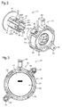
Fig. 1] Fig. 1 is an exploded perspective view of a vehicle operation apparatus according to an embodiment of the invention, seen from a front side. - [
Fig. 2] Fig. 2 is an exploded perspective view of a pressing operation member of the vehicle press-operation apparatus seen from a back side. - [
Fig. 3] Fig. 3 is a front view of the press-operation member. - [
Fig. 4] Fig. 4 is a side view of the vehicle operation apparatus. - [
Fig. 5] Fig. 5 is a sectional view taken along line V-V ofFig. 4 . - [
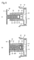
Fig. 6 ] (a) is a sectional view taken along line VI-VI ofFig. 5 , and (b) is a sectional side view showing a condition in which an operating knob which is a member to be operated moves rearward, from the condition of (a), accompanying a break of a breakable portion. - [
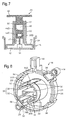
Fig. 7] Fig. 7 is a sectional view taken along line VII-VII ofFig. 5 . - [
Fig. 8] Fig. 8 is a perspective view showing a base member of the pressing operation member. - [
Fig. 9] Fig. 9 is a front view of the base member. - [
Fig. 10] Fig. 10 is a perspective view of the operating knob seen from the back side. - [
Fig. 11] Fig. 11 is a perspective view of the operating knob seen from the front side. - [
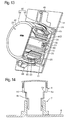
Fig. 12] Fig. 12 is a sectional perspective view showing a condition in which the operating knob is in a pressing restriction position. - [
Fig. 13] Fig. 13 is a sectional perspective view showing a condition in which the operating knob moves more rearward than the pressing restriction position accompanying a break of the breakable portion. - [
Fig. 14] Fig. 14 is a sectional view of a heretofore known vehicle operation apparatus. - Preferred embodiments of the invention will be described referring to
Figs. 1 to 13 . - A vehicle operation apparatus according to the embodiment includes a press-
operation member 10, acircuit substrate 12, and apanel 14. Thepanel 14 is mounted in an appropriate place (for example, on an instrument panel) inside a vehicle interior, and thecircuit substrate 12 is fixed to the reverse of thepanel 14. The press-operation member 10 is fixed to thecircuit substrate 12 in a condition in which it passes through an unshown through hole provided in thepanel 14, and receives a pressing operation in a direction approximately perpendicular to thecircuit substrate 12 from the front side of thepanel 14 and receives pressure with a certain amount of force or more which exceeds a normal operation force, to thereby change in shape in such a way that the amount of protrusion of thepressing operation member 10 decreases. Details thereof will be described hereafter. - The press-
operation member 10 includes abase member 18 fixed to thecircuit substrate 12 and anoperating knob 20 mounted in thebase member 18 in such a way as to protrude farther on the vehicle interior side than thebase member 18. Theoperating knob 20 corresponds to a member to be operated, which receives the pressing operation. - The
base member 18 has aninside cylinder portion 22, anoutside cylinder portion 24, anannular wall 26, and a plurality of mountingportions 28, and these are integrally formed from, for example, a synthetic resin. - The
inside cylinder portion 22 has a hollow cylindrical shape having a central axis in a direction parallel to the pressing operation direction, and has abottom wall 23 at its rear end. Theinside cylinder portion 22 has guide holdingportions 30, which hold theoperating knob 20, in appropriate places (in the drawings, four places circumferentially spaced 90° from each other) on its outer peripheral surface. Theguide holding portions 30 hold theoperating knob 20 in such a way that theoperating knob 20 can slide (move forward and rearward) in a direction parallel to the pressing operation direction. - Each
guide holding portion 30 has a pair ofholding protrusions 32 protruding inward from an inner peripheral surface of theinside cylinder portion 22. The pairedholding protrusions 32 extend in a direction parallel to the central axis while being spaced a certain distance L away from each other in a circumferential direction of theinside cylinder portion 22. That is, a space for allowing theoperating knob 20 to slide is secured between theholding protrusions 32. -
Retentive pieces inside cylinder portion 22. Theretentive pieces operating knob 20 coming off from theinside cylinder portion 22, as well as extending forward from back end positions of the corresponding spaces, each have a front end which can bend in a radial direction, and respectively have inwardly protrudingretentive protrusions Figs. 8 and9 ). - The
outside cylinder portion 24, having axial dimensions smaller than those of theinside cylinder portion 22, is formed in such a way as to encircle theinside cylinder portion 22 all around from radially outside theinside cylinder portion 22, and a rear end portion (to be exact, a portion slightly closer to the front side than the rear end) of theoutside cylinder portion 24 connects with an outer peripheral surface at the rear end of theinside cylinder portion 22 via the annular wall 26 (Fig. 5 ). - The mounting
portions 28 protrude radially outward from corresponding appropriate places of the outer peripheral surface of theoutside cylinder portion 24. A bolt throughhole 29 passing through eachmounting portion 28 in an axial direction (a direction parallel to the pressing operation direction) is provided in eachmounting portion 28. Meanwhile, bolt throughholes 13 are provided in positions of thecircuit substrate 12 corresponding to the bolt through holes 29 (Fig. 3 ), and bolts inserted into the corresponding two bolt throughholes base member 18 to thecircuit substrate 12 in a condition in which the rear end surface of theoutside cylinder portion 24 is in contact with thecircuit substrate 12. - The
operating knob 20 is held in thebase member 18 in such a way as to move rearward (slide) in the pressing operation direction by receiving a pressing operation in the pressing operation direction. - Specifically, the
operating knob 20 has an operatedplate 42 which receives a pressing operation with a finger or the like, and a heldcylinder 44 extending rearward from the rear surface of the operatedplate 42. - The held
cylinder 44 has four guidedportions portions 48, positioned a predetermined distance radially inwardly of the guidedportions - Each guided
portion 46A to 46D has a flat plate-like shape perpendicular to the radial direction of the heldcylinder 44. Then, each guidedportion 46A to 46D is inserted between the holdingprotrusions 32, which configures eachguide holding portion 30 in theinside cylinder portion 22 of thebase member 18, in a direction parallel to the pressing operation direction to be thereby held in such a way as to be slidable in the same direction. - Also, a rectangular through
hole 45 having predetermined dimensions in a front-rear direction of the upper and lower guidedportions portions retentive protrusions retentive pieces base member 18 are fitted in the corresponding through holes 45. The front-rear direction positions and dimensions of the throughholes 45 are set in such a way that theretentive protrusions knob 20 from coming off from theinside cylinder portion 22 while allowing the operatingknob 20 to slide. - Furthermore, a pressing operation bar 47 (
Figs. 2 and the like) extends more rearward than the rear end of the lower guidedportion 46D. - Meanwhile,
stopper ribs 50 in positions corresponding to the guidedportions 46A to 46D are protruded from the front side surface of thebottom wall 23 of theinside cylinder portion 22. In the embodiment, theribs 50 extend in directions perpendicular to the guidedportions 46A to 46D, that is, in the radial direction, and come in contact with the rear ends of the guidedportions 46A to 46D, thereby restricting a slide stroke of the operatingknob 20. That is, the rear ends of the guidedportions 46A to 46D configure contact portions which come in contact with theribs 50 to thereby prevent the operatingknob 20 from sliding in a direction in which it moves more rearward than its contact position (pressing restriction position), and theribs 50, which come in contact with the contact portions, configure stoppers which restrict the slide. - Also, a through
hole 52 for allowing thepressing operation bar 47 to pass through thebottom wall 23 is provided in thebottom wall 23. Meanwhile, aswitch element 15 which is an operation detector is provided in a position on thecircuit substrate 12 corresponding to thepressing operation bar 47. Theswitch element 15 outputs a detection signal by receiving the pressure of thepressing operation bar 47 when the operatingknob 20 slides in such a way as to move rearward to the pressing restriction position. - Furthermore, as a feature of the apparatus, the rear ends of the guided
portions 46A to 46C, among the rear ends of the guidedportions 46A to 46D configuring the contact portions, configure breakable portions, and the breakable portions have a shape such that they are broken by receiving a reaction force from theribs 50 when the operatingknob 20 receives pressure with a certain amount of force or more which is larger than the normal pressing operation force, thereby allowing the operatingknob 20 to slide in a direction in which the operatingknob 20 moves more rearward than the pressing restriction position. Specifically, as shown inFig. 6(a) , with a rearmost end region left in the rear end portion of each guidedportion 46A to 46C, a rectangular throughhole 54 passing through each guidedportion 46A to 46D is formed in a position closer to the front side than the rearmost region, whereby the rearmost end region is configured as alinear beam portion 56 perpendicular to eachrib 50. Then, the length and cross-sectional shape of thebeam portion 56 are set in such a way that, when a certain amount of pressing load or more is applied to the operatingknob 20, the intermediate region of thebeam portion 56 is broken, as shown in an A portion ofFig. 6 (b) , by a reaction force received from therib 50 in pressure contact with the intermediate region. - Meanwhile, an operation side breakable portion is formed in the rear end portion of the guided
portion 46D in which thepressing operation bar 47 is provided. The operation side breakable portion is broken by a reaction force which thepressing operation bar 47 receives from theswitch element 15 when the operatingknob 20 receives a certain amount of pressure or more. Specifically, as shown inFig. 7 , in the same way as in the guidedportions 46A to 46C, with a rearmost end region of the guidedportion 46D left in the rear end portion of the guidedportion 46D, a rectangular throughhole 54D is formed in a position closer to the front side than the rearmost end region, whereby the rearmost end region is configured as alinear beam portion 56D perpendicular to thepressing operation bar 47. Then, the length and cross-sectional shape of thebeam portion 56D are set in such a way that the intermediate region of thebeam portion 56D is broken by a reaction force received from theswitch element 15 via thepressing operation bar 47 when a certain amount of pressing load or more is applied to the operatingknob 20. The break strength of thebeam portion 56D is set in such a way that a pressing load when thebeam portion 56D breaks is equivalent to a pressing load when eachbeam portion 56 breaks. - The operating apparatus according to the embodiment is provided with a kind of dial operation member (rotating operation member) 60 shown in
Figs. 12 and13 in addition to thevehicle operation member 10. Thedial operation member 60, being one which receives a rotating operation, includes a ring-like base member 62 and a dial member (member to be operated) 64 of a ring-like shape in the same way. Also, thebase member 18 is loaded with an unshown spring mechanism which makes an operator feel a click along with a rotation of thedial operation member 60. - The
base member 62 is held on the press-operation member 10 side of thebase member 18 in such a way as to be rotatable around an axis the same as the central axis of thebase member 18. Specifically, a plurality of holdingpieces 38 are extended forward from theoutside cylinder portion 24 of thebase member 18, and the holdingpieces 38 hold thebase member 62 in such a way as to embrace it from radially outside. - The
dial member 64 has a supportedcylinder 65 supported from radially inside by thebase member 62, adial ring 66 provided along the outer perimeter of the operatedplate 42 of the operatingknob 20, and a plurality of connectingportions 68 radially connecting thedial ring 66 and supportedcylinder 65 in such a way that thedial ring 66 and supportedcylinder 65 rotate integrally. The supportedcylinder 65 is engaged with thebase member 62 in such a way as to rotate integrally with thebase member 62 and move rearward to thebase member 62 in a direction of the pressing force, in the same way as the operatingknob 20, when thedial member 64 receives a certain amount of pressing force or more. - Means which allow the rearward movement of the
dial member 64 are not limited. For example, a breakable portion similar to the breakable portions of the press-operation member 10 side (beam portions dial member 64, and means may be such that thedial member 64 is held on thebase member 62 so as to be slidable in the front-rear direction, and biased to the front side by a spring or the like, and when receiving pressure, moves rearward accompanying a compressive deformation of the spring. - In the operating apparatus according to the invention, the
dial operation member 60 is not essential. That is, thepressing operation member 10 may be used alone. - Next, an action of the operation apparatus will be described.
- The operating
knob 20 of thepressing operation member 10, in a condition before it receives a pressing operation, is held in a position in which thepressing operation bar 47 of the operatingknob 20 lightly touches theswitch element 15, or is spaced away from theswitch element 15. When the operatingknob 20 is pressingly operated from the position, the operatingknob 20 slides in a direction in which the operatingknob 20 moves rearward in the pressing operation direction, and the pressing operation force is applied to theswitch element 15 by thepressing operation bar 47, and theswitch element 15 outputs a detection signal. At this time, eachguide holding portion 30 of thebase member 18 guides each guidedportion 46A to 46D of the operatingknob 20, thereby stabilizing the slide of the operatingknob 20. Also, a rearward movement position of the operatingknob 20 is restricted to a position (the pressing restriction position) in which thebeam portions 56 at the rear ends of the guidedportions 46A to 46D come in contact with theribs 50 on the base member 18 (Fig. 12 ). - On the other hand, when a certain amount of pressing force or more (a force significantly larger than the normal pressing operation force) is applied to the operating
knob 20, for example, the case where a passenger strongly presses against the operatingknob 20 or the like, due to a vehicular collision or the like, thebeam portions 56 of the guidedportions 46A to 46C and thebeam portion 56D of the guidedportion 46D approximately simultaneously break due to the pressing force, whereby the operatingknob 20 moves more rearward from the pressing restriction position (Fig. 13 ). Specifically, an intermediate region of the beam portion (breakable portion) 56 at the rear end of each guidedportion 46A to 46C receives a reaction force from eachrib 50 in response to the pressing force, while an intermediate region of the beam portion (breakable portion on the operation side) 56D of the guidedportion 46D receives a reaction force in response to the pressing force, from theswitch element 15, via thepressing operation bar 47. These cause each beam portion to break under approximately the same conditions. - The amount of protrusion of the press-
operation member 10 from thepanel 14 decreases rapidly owing to the rearward movement of the operatingknob 20 accompanying the break. Also, in the embodiment, due to the application of the pressing force, thedial ring 66 around the operatingknob 20 also moves rearward to thebase member 62 integrally with the supportedcylinder 65, which guarantees a rapid reduction in the amount of protrusion of the whole operation member. - At the time of the rearward movement, a reaction force equivalent to the pressing force applied to the operating
knob 20 is applied directly to thebeam portions 56 from theribs 50 which are the stoppers of thebase member 18, and thebeam portions 56 break in a position on which the reaction force acts. This makes it easy to specify a relationship between the pressing force and a break load of thebeam portions 56 which are the breakable portions. Also, as the direction of rearward movement of the operatingknob 20 accompanying the break is restricted by theguide holding portions 30 of thebase member 18, maldistribution of a pressing load caused by an inclination of the operatingknob 20 is unlikely to occur. These points make it easy to design eachbeam portion 56 which is a breakable portion. - In particular, in the embodiment, the
ribs 50 which are the stoppers of thebase member 18 and thebeam portions 56 which is to come in contact with theribs 50 are provided respectively in a plurality of positions arranged on a plane perpendicular to the pressing operation direction of the operatingknob 20, whereby a reaction force which thebeam portions 56 receive from theribs 50 is equalized. This makes it easier to design thebeam portions 56. Also, as the break strength of this kind ofbeam portion 56 can be calculated based on a general bending theory, it is easy to design the beam portions. The same also applies to thebeam portion 56D which is the breakable portion on the operation side. - In the invention, the contact portions (in the illustrated example, the beam portions 56) do not necessarily have to be provided in portions to be pressed, and the contact portions may be provided separately from the portions be pressed. However, that the rear end portions of the guided portions configure the contact portions, as heretofore described, enables a further simplification of the structure.
- In particular, with respect to the
pressing operation member 10 in the illustrated example, the simple structure wherein at least the rear end portion of each guidedportion 46A to 46D is formed into a plate, and the throughhole 54 is provided in the rear end portion, makes it possible to form abeam portion 56 suitable for the breakable portion in a portion closer to the leading end side than the throughhole 54. - In the invention, the breakable portions may be included in the stoppers on the base member side, rather than in the contact portions on the member to be operated (in the illustrated example, the operating knob 20) side. For example, beam-like stoppers may be formed in the base member, and the stoppers may be broken by a pressing force received from the contact portions on the member to be operated.
- For example, in the internal protrusion regulations in China and Europe, when an operation apparatus has a protruding object protruding 9.5mm or more from a panel, it is required to reduce the amount of protrusion of the protruding object to 9.5mm or less when a static load of approximately 380N acts on the protruding object. In order to meet the requirement with the operating apparatus shown in
Figs. 1 to 13 , it is sufficient to design thebeam portions - In the operating apparatus, as the four
beam portions knob 20 moves rearward by receiving a pressing load of 380N, it is sufficient that the beam portions are designed in such a way that each beam portion breaks by receiving a load of 380/4=95(N), that is, in such a way that the break load Pf of each beam portion is 95N. - When a load P acts on the intermediate regions of the
beam portions -

beam portions beam portions 
- Herein, when the plate thickness of the guided
portions 46A to 46D in which the beam portions are formed (that is, the width of the beam portions) is taken to be t, and the thickness of the beam portions (a distance from the rear end of each throughhole 54 to the rear end of each guidedportion 46A to 46D) is taken to be d2, the section modulus Z of thebeam portions 
- When the equation (2) and equation (3) are substituted into the equation (1), the following equation is obtained.

- Herein, as the maximum bending stress σmax when the
beam portions beam portions knob 20 receives a pressing stress of approximately 380N. - As described above, the invention provides a vehicle press-operation member wherein it is easy to design a breakable portion which is broken in order to reduce an amount of protrusion from a panel when a certain amount of pressing force or more is applied, and it is possible to increase the reliability of a reduction in the amount of protrusion when the pressing force acts, and a vehicle operation apparatus provided with the vehicle press-operation member. Specifically, the invention provides a vehicle press-operation member which is provided on a panel in a vehicle interior in such a way as to protrude on the vehicle interior side from a surface of the panel and to receive a pressing operation, and is configured in such a way that the amount of protrusion decreases by receiving pressure with a certain amount of force or more. The vehicle press-operation member includes a base member mounted on the panel or a member fixed to the panel, and a member to be operated which is mounted on the base member in such a way as to protrude on the vehicle interior side from the base member, and receives a pressing operation. The base member has a guide holding portion which holds, while guiding, the member to be operated in such a way that the member to be operated slides to the base member in a direction parallel to the pressing direction, and a stopper which comes in contact with the member to be operated to thereby restrict the member to be operated from sliding in a direction in which the member to be operated moves more rearward than a predetermined pressing restriction position, and the member to be operated has a guided portion which fits in the guide holding portion and is guided by the guide holding portion, and a contact portion which comes in contact with the stopper of the base member to thereby prevent the slide in the direction in which the member to be operated moves rearward. Either of the stopper or the contact portion configures a breakable portion having a shape such that it is broken by receiving a pressing force from the other in the pressing direction when the member to be operated receives pressure with a certain amount of force or more, thereby allowing a further slide of the member to be operated in the pressing direction.
- In the pressing operation member, when the member to be operated is pressed with the normal operation force, the member to be operated slides with the pressing force in a direction in which it moves rearward, but the slide is stopped in a position in which the contact portion of the member to be operated and the stopper of the base member come in contact with, thereby preventing a further rearward movement. That is, the stopper fulfils its original function of restricting the pressing operation stroke of the member to be operated to a stroke up to the pressing restriction position.
- On the other hand, when a large pressing force is applied to the member to be operated, for example, by the passenger of the vehicle making a strong contact with the member to be operated or the like, the contact portion of the member to be operated makes pressure contact with the stopper on the base member side with a pressure corresponding to the pressing force, and the breakable portion included in the contact portion or stopper is broken by the pressure contact. Owing to the break, the member to be operated moves rearward toward the base member side up to a deeper position than the pressing restriction position, whereby the amount of protrusion of the whole of the pressing operation member from the panel decreases rapidly, and the passenger's safety is secured.
- When pressing, a reaction force equivalent to the pressing force is applied to the contact portion from the stopper of the base member, and the break occurs in that position, thus making it easy to specify a relationship between the pressing force and the break load of the breakable portion. Also, as a direction of rearward movement of the member to be operated accompanying the break is fixed by the guide holding portion, the maldistribution of the pressing load caused by an inclination of the member to be operated is unlikely to occur. Consequently, it is easy to design the breakable portion.
- In particular, in the event that the stoppers of the base member and the contact portions of the member to be operated are provided respectively in a plurality of positions arranged on a plane perpendicular to the pressing direction of the member to be operated, and so are the contact portions of the member to be operated, a break load which each breakable portion receives from the corresponding stopper or contact portion is equalized, thereby making it easier to design the breakable portions.
- For example, the adoption of an arrangement such that the member to be operated has the guided portions one each in a plurality of positions arranged around a specific central axis parallel to the pressing direction of the member to be operated, and the rear end portions of two or more of the guided portions among the guided portions configure the contact portion, further simplifies the structure by utilizing the rear end portions of the guided portions as the contact portions.
- Also, as a specific configuration of the breakable portion, one is preferable wherein the breakable portion, which includes a beam portion extending in a direction perpendicular to the pressing direction of the member to be operated, and breaks by a longitudinally intermediate region of the beam portion receiving the pressing force. With a breakable portion including this kind of beam portion, it is possible to calculate the break strength of the beam portion based on the general bending theory. Consequently, it is easy to design the breakable portion.
- For example, when utilizing the rear end portion of the guided portion as the contact portion as heretofore described, a structure is preferable wherein the rear end portion of the guided portion configuring the contact portion is formed into a plate, a through hole passing through an end portion of the plate in a direction of the plate thickness is provided, a portion closer to the leading end side than the through hole forms a beam portion extending in a direction perpendicular to the pressing direction of the member to be operated, and a longitudinally intermediate region of the beam portion breaks by receiving the pressing force. In this structure, a beam portion suitable for the breakable portion is formed with a simple structure wherein a through hole is provided in a plate-like rear end portion of the guided portion.
- Also, the invention is an operation apparatus, which is provided in a vehicle and includes a panel provided in such a way as to face inside a vehicle interior, a circuit substrate fixed to the reverse of the panel, the vehicle press-operation member which is provided on the panel so as to be operable in such a way as to protrude on the vehicle interior side from the surface of the panel and changes in shape in such a way that the amount of protrusion decreases by receiving a certain amount of pressing force or more, and an operation detector which is provided on the circuit substrate and outputs an electrical signal when the member to be operated of the vehicle press-operation member is operated up to the pressing restriction position, wherein the base member of the vehicle press-operation member is fixed to the panel.
- In the operating apparatus, by providing the member to be operated of the vehicle press-operation member with a pressing operation portion which is provided in a position differing from the contact portion and, in accordance with a pressing operation of the member to be operated, transmits the pressing force to the operation detector, and a breakable portion on the operation side, which breaks with a reaction force which the press-operation portion receives from the operation detector when the member to be operated receives a certain amount of pressure or more, the pressing operation portion also can be utilized as a breakable portion. In this case, it is sufficient to set the shape of the breakable portion on the operation side in such a way that a pressing load when the breakable portion on the operation side breaks is equal to a pressing load when the breakable portion breaks.
Claims (7)
- A vehicle press-operation member which is provided on a panel in a vehicle interior in such a way as to protrude on the vehicle interior side from a surface of the panel, and changes in shape in such a way that the amount of protrusion thereof decreases by receiving a certain amount of force or more, comprising:a base member mounted on the panel or a member fixed to the panel; anda member to be operated which is mounted on the base member in such a way as to protrude on the vehicle interior side from the base member and receives a pressing operation, whereinthe base member has a guide holding portion which holds, while guiding, the member to be operated in such a way that the member to be operated slides to the base member in a direction parallel to the pressing direction, and a stopper which, by coming in contact with the member to be operated, restricts the member to be operated from sliding in a direction in which the member to be operated moves more rearward than a predetermined pressing restriction position,the member to be operated has a guided portion which fits in the guide holding portion and is guided by the guide holding portion, and a contact portion which, by coming in contact with the stopper of the base member, prevents the slide in the direction in which the member to be operated moves rearward,
andeither of the stopper or the contact portion includes a breakable portion having a shape such that it is broken by receiving a pressing force from the other in the pressing direction when the member to be operated receives pressure with a certain amount of force or more, thereby allowing the member to be operated to slide in a direction in which the member to be operated moves still more rearward than the pressing restriction position. - The vehicle press-operation member according to claim 1, wherein
the stoppers of the base member and the contact portions of the member to be operated are provided respectively in a plurality of positions arranged on a plane perpendicular to the pressing direction of the member to be operated. - The vehicle press-operation member according to claim 2, wherein
the member to be operated has the guided portions one each in a plurality of positions arranged on a plane perpendicular to the pressing direction of the member to be operated, and the rear end portions of two or more of the guided portions, among the guided portions, configure the contact portions. - The vehicle press-operation member according to any one of claims 1 to 3, wherein
the breakable portion which includes a beam portion extending in a direction perpendicular to the pressing direction of the member to be operated, wherein a longitudinally intermediate region of the beam portion receives the pressing force to thereby break. - The vehicle press-operation member according to claim 3, wherein
the rear end portion of the guided portion configuring the contact portion is formed into a plate, a through hole passing through an end portion of the plate in a direction of the plate thickness is provided, a portion closer to the leading end side than the through hole forms a beam portion extending in a direction perpendicular to the pressing direction of the member to be operated, and a longitudinally intermediate region of the beam portion breaks by receiving the pressing force. - A vehicle operation apparatus, which is provided in a vehicle, comprising:a panel provided in such a way as to face inside a vehicle interior;a circuit substrate fixed to the reverse of the panel;the vehicle press-operation member according to any one of claims 1 to 5, which is provided on the panel so as to be operable in such a way as to protrude on the vehicle interior side from the surface of the panel and changes in shape in such a way that the amount of protrusion decreases by receiving a certain amount of pressure or more; andan operation detector which is provided on the circuit substrate and outputs an electrical signal when the member to be operated of the vehicle press-operation member is operated up to the pressing restriction position, whereinthe base member of the vehicle press-operation member is fixed to the panel.
- The vehicle operation apparatus according to claim 6, wherein
the member to be operated of the vehicle press-operation member has a pressing operation portion which is provided in a position differing from the contact portion and transmits the pressing force to the operation detector in accordance with a pressing operation of the member to be operated, and an operation side breakable portion which breaks with a reaction force, which the pressing operation portion receives from the operation detector when the member to be operated receives a certain amount of pressure or more, wherein the shape of the operation side breakable portion is set in such a way that a pressing load when the operation side breakable portion breaks is equal to a pressing load when the breakable portion breaks.
Applications Claiming Priority (2)
| Application Number | Priority Date | Filing Date | Title |
|---|---|---|---|
| JP2009265995A JP5218381B2 (en) | 2009-11-24 | 2009-11-24 | VEHICLE PRESSING OPERATION MEMBER AND VEHICLE OPERATING DEVICE EQUIPPED |
| PCT/JP2010/006605 WO2011064954A1 (en) | 2009-11-24 | 2010-11-10 | Vehicle press-operation member, and vehicle press-operation apparatus comprising same |
Publications (2)
| Publication Number | Publication Date |
|---|---|
| EP2506278A1 true EP2506278A1 (en) | 2012-10-03 |
| EP2506278A4 EP2506278A4 (en) | 2015-04-01 |
Family
ID=44066069
Family Applications (1)
| Application Number | Title | Priority Date | Filing Date |
|---|---|---|---|
| EP10832810.5A Withdrawn EP2506278A4 (en) | 2009-11-24 | 2010-11-10 | Vehicle press-operation member, and vehicle press-operation apparatus comprising same |
Country Status (4)
| Country | Link |
|---|---|
| EP (1) | EP2506278A4 (en) |
| JP (1) | JP5218381B2 (en) |
| CN (1) | CN102484008B (en) |
| WO (1) | WO2011064954A1 (en) |
Families Citing this family (1)
| Publication number | Priority date | Publication date | Assignee | Title |
|---|---|---|---|---|
| JP6209004B2 (en) * | 2013-07-23 | 2017-10-04 | 株式会社ユーシン | Air conditioning operating device for vehicles. |
Family Cites Families (7)
| Publication number | Priority date | Publication date | Assignee | Title |
|---|---|---|---|---|
| JPH02129817A (en) * | 1988-11-09 | 1990-05-17 | Matsushita Electric Ind Co Ltd | push button device |
| JP2003162936A (en) * | 2001-11-27 | 2003-06-06 | Kenwood Corp | Push button switch device |
| JP4173336B2 (en) * | 2002-08-22 | 2008-10-29 | アルプス電気株式会社 | Operation mechanism of in-vehicle composite operation type electric parts |
| JP2005150040A (en) * | 2003-11-19 | 2005-06-09 | Pioneer Electronic Corp | Operating device |
| JP2006253063A (en) * | 2005-03-14 | 2006-09-21 | Alpine Electronics Inc | Operating device |
| CN101490775B (en) * | 2006-07-12 | 2011-07-06 | 住友电装株式会社 | vehicle switch |
| US8084703B2 (en) * | 2007-12-18 | 2011-12-27 | Panasonic Corporation | Rotating operation type electronic component, and electronic device including the same |
-
2009
- 2009-11-24 JP JP2009265995A patent/JP5218381B2/en not_active Expired - Fee Related
-
2010
- 2010-11-10 WO PCT/JP2010/006605 patent/WO2011064954A1/en not_active Ceased
- 2010-11-10 EP EP10832810.5A patent/EP2506278A4/en not_active Withdrawn
- 2010-11-10 CN CN201080040632.0A patent/CN102484008B/en not_active Expired - Fee Related
Also Published As
| Publication number | Publication date |
|---|---|
| CN102484008A (en) | 2012-05-30 |
| CN102484008B (en) | 2014-10-22 |
| WO2011064954A1 (en) | 2011-06-03 |
| JP2011113645A (en) | 2011-06-09 |
| EP2506278A4 (en) | 2015-04-01 |
| JP5218381B2 (en) | 2013-06-26 |
Similar Documents
| Publication | Publication Date | Title |
|---|---|---|
| JP4313608B2 (en) | Electronics | |
| EP2775373B1 (en) | Device for detecting amount of pedal operation | |
| US7908713B2 (en) | Operating knob | |
| JP2008041654A (en) | Switch for vehicle | |
| EP2907700B1 (en) | Horn system | |
| US20210031684A1 (en) | Steering wheel | |
| CN111284551B (en) | Steering column for vehicle | |
| EP2910450A1 (en) | Steering column assembly | |
| JP2005186677A (en) | Bumper structure for vehicles | |
| CN105320208A (en) | Control knob device | |
| SE1550581A1 (en) | Vehicle comprising collision control systeSm, collision control system and method | |
| US20190092289A1 (en) | Rearward movement preventing device of pedal device for vehicle | |
| CN101490775B (en) | vehicle switch | |
| US20040168871A1 (en) | Retaining cap for a protective bellows | |
| US10676120B2 (en) | Adjustable steering column for motor vehicles with energy absorber for vehicle crashes | |
| EP2506278A1 (en) | Vehicle press-operation member, and vehicle press-operation apparatus comprising same | |
| JP7573174B2 (en) | Steering device | |
| JP2009523303A (en) | Switches, especially steering column switches for automobiles | |
| KR100522870B1 (en) | Mounting Structure of Air-Bag Case | |
| US9162598B2 (en) | Moveable vehicle armrest assembly | |
| EP2720242B1 (en) | Composite operating device | |
| WO1999049160A1 (en) | Key operated rotary switch for disabling an automobile air bag supplemental restraint system | |
| CN113557166A (en) | Seat regulating switch | |
| US4862761A (en) | Automobile steering assembly with a telescopic steering column and a pull-away device for the upper steering column part | |
| JP2012151011A (en) | Rotary operation member for vehicle, and rotary operation device for vehicle with it |
Legal Events
| Date | Code | Title | Description |
|---|---|---|---|
| PUAI | Public reference made under article 153(3) epc to a published international application that has entered the european phase |
Free format text: ORIGINAL CODE: 0009012 |
|
| 17P | Request for examination filed |
Effective date: 20120216 |
|
| AK | Designated contracting states |
Kind code of ref document: A1 Designated state(s): AL AT BE BG CH CY CZ DE DK EE ES FI FR GB GR HR HU IE IS IT LI LT LU LV MC MK MT NL NO PL PT RO RS SE SI SK SM TR |
|
| DAX | Request for extension of the european patent (deleted) | ||
| RA4 | Supplementary search report drawn up and despatched (corrected) |
Effective date: 20150303 |
|
| RIC1 | Information provided on ipc code assigned before grant |
Ipc: H01H 13/14 20060101AFI20150225BHEP |
|
| GRAP | Despatch of communication of intention to grant a patent |
Free format text: ORIGINAL CODE: EPIDOSNIGR1 |
|
| INTG | Intention to grant announced |
Effective date: 20150625 |
|
| STAA | Information on the status of an ep patent application or granted ep patent |
Free format text: STATUS: THE APPLICATION IS DEEMED TO BE WITHDRAWN |
|
| 18D | Application deemed to be withdrawn |
Effective date: 20151106 |