EP2506228A1 - A container anti-intrusion sensor device - Google Patents
A container anti-intrusion sensor device Download PDFInfo
- Publication number
- EP2506228A1 EP2506228A1 EP11425079A EP11425079A EP2506228A1 EP 2506228 A1 EP2506228 A1 EP 2506228A1 EP 11425079 A EP11425079 A EP 11425079A EP 11425079 A EP11425079 A EP 11425079A EP 2506228 A1 EP2506228 A1 EP 2506228A1
- Authority
- EP
- European Patent Office
- Prior art keywords
- sensor device
- container
- strip
- intrusion sensor
- intrusion
- Prior art date
- Legal status (The legal status is an assumption and is not a legal conclusion. Google has not performed a legal analysis and makes no representation as to the accuracy of the status listed.)
- Granted
Links
Images


Classifications
-
- G—PHYSICS
- G08—SIGNALLING
- G08B—SIGNALLING SYSTEMS, e.g. PERSONAL CALLING SYSTEMS; ORDER TELEGRAPHS; ALARM SYSTEMS
- G08B13/00—Burglar, theft or intruder alarms
- G08B13/16—Actuation by interference with mechanical vibrations in air or other fluid
- G08B13/1654—Actuation by interference with mechanical vibrations in air or other fluid using passive vibration detection systems
-
- G—PHYSICS
- G08—SIGNALLING
- G08B—SIGNALLING SYSTEMS, e.g. PERSONAL CALLING SYSTEMS; ORDER TELEGRAPHS; ALARM SYSTEMS
- G08B13/00—Burglar, theft or intruder alarms
- G08B13/02—Mechanical actuation
- G08B13/14—Mechanical actuation by lifting or attempted removal of hand-portable articles
- G08B13/1436—Mechanical actuation by lifting or attempted removal of hand-portable articles with motion detection
-
- G—PHYSICS
- G08—SIGNALLING
- G08B—SIGNALLING SYSTEMS, e.g. PERSONAL CALLING SYSTEMS; ORDER TELEGRAPHS; ALARM SYSTEMS
- G08B13/00—Burglar, theft or intruder alarms
- G08B13/02—Mechanical actuation
- G08B13/14—Mechanical actuation by lifting or attempted removal of hand-portable articles
- G08B13/1481—Mechanical actuation by lifting or attempted removal of hand-portable articles with optical detection
-
- G—PHYSICS
- G08—SIGNALLING
- G08B—SIGNALLING SYSTEMS, e.g. PERSONAL CALLING SYSTEMS; ORDER TELEGRAPHS; ALARM SYSTEMS
- G08B13/00—Burglar, theft or intruder alarms
- G08B13/18—Actuation by interference with heat, light, or radiation of shorter wavelength; Actuation by intruding sources of heat, light, or radiation of shorter wavelength
- G08B13/181—Actuation by interference with heat, light, or radiation of shorter wavelength; Actuation by intruding sources of heat, light, or radiation of shorter wavelength using active radiation detection systems
- G08B13/183—Actuation by interference with heat, light, or radiation of shorter wavelength; Actuation by intruding sources of heat, light, or radiation of shorter wavelength using active radiation detection systems by interruption of a radiation beam or barrier
- G08B13/186—Actuation by interference with heat, light, or radiation of shorter wavelength; Actuation by intruding sources of heat, light, or radiation of shorter wavelength using active radiation detection systems by interruption of a radiation beam or barrier using light guides, e.g. optical fibres
-
- G—PHYSICS
- G08—SIGNALLING
- G08B—SIGNALLING SYSTEMS, e.g. PERSONAL CALLING SYSTEMS; ORDER TELEGRAPHS; ALARM SYSTEMS
- G08B29/00—Checking or monitoring of signalling or alarm systems; Prevention or correction of operating errors, e.g. preventing unauthorised operation
- G08B29/18—Prevention or correction of operating errors
- G08B29/185—Signal analysis techniques for reducing or preventing false alarms or for enhancing the reliability of the system
- G08B29/188—Data fusion; cooperative systems, e.g. voting among different detectors
Definitions
- the present invention relates to a container anti-intrusion sensor device.
- This problem is usually resolved by equipping the containers with key and or combination-based door-locking devices, preferably equipped with electronic devices able to send an alarm signal, via radio, GPS, etc., to an external control unit in the event of the locking device being forced or broken.
- monitoring systems based on various types of sensors
- temperature, humidity, luminosity, acceleration, proximity and smoke sensors which are preferably installed in combination with each other inside the container to guarantee good reliability, by redundancy, in detecting break-ins or tampering at any point of the container.
- the object of the present invention is that of making a container anti-intrusion sensor device, this device being able to eliminate the above-described drawbacks in an efficient and economic manner.
- a container anti-intrusion sensor device is made according to attached claims.
- a container of known type is indicated, as a whole, by reference numeral 1 and is defined by a box-shaped body delimited laterally by a wall 2 made of corrugated sheet metal and closed by a door 3.
- the inner surface of at least one wall 2 of the container 1 is fitted with at least one anti-intrusion sensor device 4 having the function of detecting any tampering or attempted break-ins and sending the associated signals to an electronic control unit 5 (of known type) for data collection, processing and transmission.
- each anti-intrusion sensor device 4 comprises a support strip 6 made of a flexible material, preferably a plastic material such as polyethylene, and fastening means 7, which enable the strip 6 to be fastened to the wall 2 and comprise a layer of magnetic material integral with a face of the strip 6.
- the fastening means 7 can have a different shape and/or nature to those of the above-described example.
- the fastening means 7 comprise a plurality of magnets, which can be at least partially embedded in the strip 6 and are set apart from each other along the same strip 6, with a pitch equal to the pitch of the corrugations of the wall 2 such that by fixing the anti-intrusion sensor device 4 in a stretched out position transversal to the corrugations of the wall 2, the magnets find themselves in correspondence to the peaks of the corrugations.
- the fastening means 7 are constituted by a layer, or discrete portions, of an adhesive material which, amongst other things, also allows the strip 6 to be fixed in cases where the wall 2 is made, or finished, with a non-metallic material.
- the strip 6 supports a plurality of sensors comprising optical sensors and vibration sensors having the function, in use, of respectively detecting any light radiation inside the container 1 and any vibration induced on the wall 2 of the container 1, and of transforming this radiation and vibration into respective electrical signals that are sent to the electronic control unit 5.
- the optical sensors are constituted by photodiodes 8, which are distributed in groups of two along the entire length of the strip 6 and are equipped with focusing optics able to guarantee a field of view capable of monitoring the space surrounding the strip 6.
- the focusing optics are constituted by cylindrical lenses able to ensure the monitoring of all the surface of the wall 2.
- an anti-intrusion sensor device 4 equipped with six photodiodes 8 with a field of view of approximately 120° each and installed on a side of the wall 2 at a height of 1.3m, namely at approximately half the height of the side, and in a transversal direction to the corrugations of this side, is able to monitor the entire side.
- the vibration sensors comprise plates 9 of a piezoelectric ceramic material solidly glued or directly deposited on the strip 6.
- the position of the plates 9 on the strip 6 is arbitrary, but preferably the plates 9 are arranged along the strip 6 in alternating positions to the pairs of photodiodes 8 and separated from each other such that when the anti-intrusion sensor device 4 is applied to the wall 2, the plates 9 always find themselves in a position to directly receive any vibrations transmitted by the wall 2.
- the plates 9 will be spaced apart from each other by a distance equal to the pitch of the peaks of the corrugations; instead, if the anti-intrusion sensor device 4 is prepared for being fixed in a transversal direction to the corrugations of the wall 2, but in a folded position so that it adheres both to the peaks and to the troughs of the corrugations of the wall 2, the plates 9 shall be spaced apart from each other by a distance greater than the pitch of the peaks such that, once the anti-intrusion sensor device 4 is applied, the plates 9 find themselves in correspondence to the troughs and the photodiodes 8 find themselves in correspondence to the peaks.
- each plate 9 is able to detect the oscillation that propagates along wall 2 and translate it into an electrical signal proportional to the intensity of oscillation.
- the reciprocal positions of the plates 9 on the strip 6 make it possible to characterize the vibration source in:
- the electrical signals generated by the optical and vibration sensors, the photodiodes 8 and the plates 9 in the case in point, are transmitted on respective electrically conductive tracks 10, preferably screen-printed on the strip 6 and electrically connected to a connector 11 arranged at one axial end of the anti-intrusion sensor device 4 that, in turn, is electrically connected to the electronic control unit 5 by an electrical cable 12.
- the electronics for conditioning and amplifying the electrical signals are also printed on the strip 6.
- the electronic control unit 5 comprises a device for detecting the opening of the door 3 and is mounted close to the door 3 ( Figure 1 ) and, normally, outside the container 1.
- the electronic control unit 5 can also be provided with a global positioning device (i.e. GPS), a processor for processing the data, a power management system for managing the powering of the sensors and a device for storing the alarms.
- a global positioning device i.e. GPS
- a processor for processing the data i.e., a processor for processing the data
- a power management system for managing the powering of the sensors
- a device for storing the alarms storing the alarms.
- the electronic control unit 5 could be capable of transmitting various types of information, for example, an alarm and an ID signal for the container 1 from which the alarm originated, to a remote monitoring station (for example, via RF radio, satellite, or Wi-Fi).
- the electronic control unit 5 is electrically connected to all of the sensor devices 4 applied to the container 1 and is preferably configured to periodically check the status of the sensor devices 4 and to generate a specific alarm in the case of them being tampered with or malfunctioning.
- This check is based on the capacity of the piezoelectric material to behave like a sensor or like an actuator according to the type of stimulus it is subjected to; in practice, the check is carried out for each anti-intrusion sensor device 4 by sending and electrical control signal to one of the plates 9 of the anti-intrusion sensor device 4 so as to provoke a vibration by means of the plate 9 itself, which is then detected and transformed into an electrical signal by the other plates 9 of the anti-intrusion sensor device 4. Based on the return signal received, the electronic control unit 5 is able to evaluate the correct positioning of the anti-intrusion sensor device 4 and the correct operation of the all the plates 9.
- the signal sent by the electronic control unit 5 to the "actuator" plate 9 and the return signal received from the "sensor” plates 9 is stored in the electronic control unit 5 at the time of installation and constitutes the ID signal that is periodically sent by the electronic control unit 5 to evaluate the operation of the anti-intrusion sensor device 4.
- the correct installation of the sensor devices 4 is checked by electrically connecting the fastening magnetic layer or magnets of each anti-intrusion sensor device 4 to the electronic control unit 5, such that the metal wall 2 becomes part of the electrical circuit of the electronic control unit 5.
- a possible detachment of the anti-intrusion sensor device 4 from the wall 2 would cause the circuit to open and would be immediately detectable by the electronic control unit 5, for example via the generation-acquisition-testing of an electrical signal along the circuit.
- the optical sensors instead of being photodiodes 8, can be defined by optical fibres 13 arranged along the strip 6 such that their visual field is sufficiently wide to monitor everywhere around the anti-intrusion sensor device 4.
- All of the optical fibres 13 arranged along the strip 6 converge to a combiner device 14, which is positioned close to the connector 11 or, in alternative, is integrated into the latter, and has the function of "merging" the bundle of optical fibres 13 into a single optical fibre so that the light radiation collected from the bundle can be detected by a normal optoelectronic receiver unit (not shown) and transformed into a corresponding electrical current signal.
- the optoelectronic receiver unit can be placed in correspondence to the combiner device 14 and connected to the electronic control unit 5 by means of simple electrical connection, or be placed in correspondence to the electronic control unit 5 and connected to the combiner device 14 by means of an optical fibre.
- the optical fibres 13 have the advantage of avoiding the application of relatively expensive optoelectronic components, such as the photodiodes 8, to the strip 6, which is preferably of the disposable type and is designed to have a life cycle equal to the period of time that the cargo of a given shipment remains inside the container 1.
- the optical fibres 13 of the previous example can be substituted by a single optical fibre 15, which is arranged in serpentine shape over almost the entire area of the strip 6 and, in use, is traversed by a light signal generated by an optoelectronic transmission unit (not shown) and received and transformed into an electrical signal by an optoelectronic receiver unit (not shown).
- the optoelectronic transmission and receiver units are each connected to a free end of the optical fibre 15 and can be placed in proximity to the strip 6 and connected to the electronic control unit 5 by means of an electrical connection, or be placed in correspondence to the electronic control unit 5 and connected to the optical fibre 15 on the strip 6 by means of a further segment of optical fibre.
- the strip 6 has larger dimensions with respect to those of the strip 6 in the previously described examples and, once fastened to the inner surface of a side of the wall 2, is preferably able to cover most of this surface.
- a possible break-in attempted on the container 1 through the side of the wall 2 equipped with a strip 6 of this type would cause the optical fibre 15 to break, with consequent interruption of the light signal and immediate detection of the anomaly by the optoelectronic receiver unit.
- the strip 6 is also equipped with vibration sensors, such as piezoelectric plates 9 for example.
- an anti-intrusion sensor device 4 of the type shown in Figures 1 and 2 namely of the type equipped with a plurality of plates 9, which permit detection of an attempted break-in using drills, cutters or grinders independently of luminosity conditions, and photodiodes 8, which permit detection of both light radiation coming from the outside, in the case of daytime break-in, and light radiation due to the use of artificial light or cutting tools such as grinders, oxyacetylene welding or similar.
- the state of the sensor devices 4 consists in an almost null signal from the photodiodes 8 due to the total impossibility of light radiation being able to penetrate inside the container 1 and in an almost null signal from the plates 9 due to the absence of vibration.
- Signals from the plates 9 are characterized by frequencies below 60 Hz, mainly due to vibrations induced by electrical tools used for breaking in scraping against the walls of the container 1.
- the alarm activation logic is based on the comparison of the signals produced by the optical sensors, the photodiodes 8 in the case in point, and the vibration sensors, the plates 9 in the case in point, with the respective reference models.
- the alarm signal is generated with known techniques, based on exceeding a threshold, gradient evaluation, etc., implemented in the electronic control unit 5 for signal processing and conditioning.
- each photodiode 8 is in a quiescent state until the threshold value is exceeded, after which the signal values of photodiode 8 are evaluated over time, multiplying them by an opportune time interval (in practice, an integral of the signal is obtained).
- the resultant value is compared with a previously stored value and if it should exceed this value, an alarm signal is returned.
- an analogue band-pass filter is implemented in the electronic control unit 5 that is centred on 50Hz (typical frequency when using tools such as drills, grinders, cutters, etc.) with a typical bandwidth of 20Hz-30Hz.
- the signal filtered in this manner is only considered when a preset threshold value is exceeded and from that moment on the product of the acquired values and the opportune time interval is calculated.
- the resultant value is compared with a previously stored value and if it should exceed this value, an alarm signal is returned.
- the electronic control unit 5 is configured to selectively assume a sleep state with minimal energy consumption and an awake state in which the electronic control unit 5 is active and able to receive and transmit electrical signals respectively from and to the sensor devices 4 and to generate and transmit any alarm signals.
- the energy management of the system constituted by the electronic control unit 5 and the sensor devices 4 also provides for the energy induced by stimuli not indicative of a break-in in course, and therefore having values below the mentioned minimum threshold, to be "recovered” and used to charge a battery or similar device for powering the electronic control unit 5.
- the vibration sensors are not of the piezoelectric type, like the plates 9, and the light radiation sensors are not optoelectronic units, like the photodiodes 8, the task of providing the "wake-up" energy is performed by current generation units, for example, by piezoelectric units specially arranged on each strip 6.
- this task can also be performed by a piezoelectric vibrational energy recovery system placed inside the electronic control unit 5.
- the system is formed by one or more piezoelectric units that, by deforming under the effect of the oscillations to which the container 1 is subjected during shipping, generate energy that is stored in a battery or similar device for powering the electronic control unit 5.
- the use of the anti-intrusion sensor device 4 enables numerous advantages to be obtained, such as, for example, the great ease of installation, application to any type of container, low cost and minimal interference with the cargo inside the container and with loading and unloading operations.
- the reduced thickness and high flexibility of the strip 6 makes it possible to roll up a series of sensor devices 4, one attached to the other or on a single continuous support strip, so as to form a compact roll, from which the individual sensor devices 4 can be unrolled and removed when they are installed.
- the anti-intrusion sensor device 4 can be integrated with other sensors for monitoring, for example, the temperature, humidity, oxygen percentage, etc., in order to guarantee the continuity of suitable conditions for the conservation and preservation of the transported goods during transportation.
Landscapes
- Physics & Mathematics (AREA)
- General Physics & Mathematics (AREA)
- Engineering & Computer Science (AREA)
- Computer Security & Cryptography (AREA)
- Burglar Alarm Systems (AREA)
Abstract
Description
- The present invention relates to a container anti-intrusion sensor device.
- As is known, one of the main problems that container freight companies must face is that of guaranteeing the integrity of the freight, especially when containers are stacked in transit areas, waiting to be loaded onto the means of transport, and are particularly subject to vandalism and/or theft.
- This problem is usually resolved by equipping the containers with key and or combination-based door-locking devices, preferably equipped with electronic devices able to send an alarm signal, via radio, GPS, etc., to an external control unit in the event of the locking device being forced or broken.
- Although effective, this solution nevertheless suffers from the drawback of not permitting the overall integrity of the container to be monitored, as it does not allow the detection, for example, of intrusion or tampering actions made on the sides of the container away from the doors.
- In an attempt to overcome this drawback, the use of monitoring systems based on various types of sensors has been proposed, for example, temperature, humidity, luminosity, acceleration, proximity and smoke sensors, which are preferably installed in combination with each other inside the container to guarantee good reliability, by redundancy, in detecting break-ins or tampering at any point of the container.
- However, in practice, the above-described solution encounters significant limits, consisting mainly in high costs due to the number of devices to be used, the quantity of data to monitor and the tuning of the algorithms for calculating the alarm thresholds. Furthermore, the application of sensors inside the container normally entails relatively high installation costs that effectively limit the use of these sensors to just new containers and not containers already in circulation.
- The object of the present invention is that of making a container anti-intrusion sensor device, this device being able to eliminate the above-described drawbacks in an efficient and economic manner.
- According to the present invention, a container anti-intrusion sensor device is made according to attached claims.
- The invention shall now be described with reference to the attached drawings, which illustrate some non-limitative embodiments, where:
-
Figure 1 shows a preferred embodiment of the sensor device of the present invention mounted on a container; -
Figure 2 is a front view, on an enlarged scale, of the sensor device inFigure 1 ; -
Figure 3 shows, in side elevation, the sensor device inFigure 2 ; -
Figure 4 shows a first variant of the sensor device inFigure 2 ; -
Figure 5 shows a second variant of the sensor device inFigure 2 mounted on a container; -
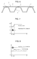
Figure 6 shows, in cross-section, a third variant of the device inFigure 2 ; and -
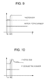
Figures 7 to 10 are diagrams showing the response of the sensor device inFigure 1 to respectively different external stimuli. - In
Figure 1 , a container of known type is indicated, as a whole, byreference numeral 1 and is defined by a box-shaped body delimited laterally by awall 2 made of corrugated sheet metal and closed by adoor 3. - The inner surface of at least one
wall 2 of thecontainer 1 is fitted with at least oneanti-intrusion sensor device 4 having the function of detecting any tampering or attempted break-ins and sending the associated signals to an electronic control unit 5 (of known type) for data collection, processing and transmission. - In particular, as shown in
Figures 1 ,2 and 3 , eachanti-intrusion sensor device 4 comprises asupport strip 6 made of a flexible material, preferably a plastic material such as polyethylene, and fastening means 7, which enable thestrip 6 to be fastened to thewall 2 and comprise a layer of magnetic material integral with a face of thestrip 6. - According to other alternative embodiments, the fastening means 7 can have a different shape and/or nature to those of the above-described example. For example, in the embodiment in
Figure 6 , the fastening means 7 comprise a plurality of magnets, which can be at least partially embedded in thestrip 6 and are set apart from each other along thesame strip 6, with a pitch equal to the pitch of the corrugations of thewall 2 such that by fixing theanti-intrusion sensor device 4 in a stretched out position transversal to the corrugations of thewall 2, the magnets find themselves in correspondence to the peaks of the corrugations. - According to a further variant (not shown), the fastening means 7 are constituted by a layer, or discrete portions, of an adhesive material which, amongst other things, also allows the
strip 6 to be fixed in cases where thewall 2 is made, or finished, with a non-metallic material. - On the opposite side to the fastening means 7, the
strip 6 supports a plurality of sensors comprising optical sensors and vibration sensors having the function, in use, of respectively detecting any light radiation inside thecontainer 1 and any vibration induced on thewall 2 of thecontainer 1, and of transforming this radiation and vibration into respective electrical signals that are sent to theelectronic control unit 5. - In the example in
Figures 2 and 3 , the optical sensors are constituted byphotodiodes 8, which are distributed in groups of two along the entire length of thestrip 6 and are equipped with focusing optics able to guarantee a field of view capable of monitoring the space surrounding thestrip 6. In a preferred embodiment, the focusing optics are constituted by cylindrical lenses able to ensure the monitoring of all the surface of thewall 2. In other words, by opportunely choosing the number, orientation and distribution of thephotodiodes 8, based on the breadth of the surfaces to be monitored and the position where theanti-intrusion sensor device 4 is fastened to the surface itself, theanti-intrusion sensor device 4 is able to detect any light radiation originating from any point of the surface that surrounds theanti-intrusion sensor device 4. - For example, for a
container 1 with an average length of 12m, ananti-intrusion sensor device 4 equipped with sixphotodiodes 8 with a field of view of approximately 120° each and installed on a side of thewall 2 at a height of 1.3m, namely at approximately half the height of the side, and in a transversal direction to the corrugations of this side, is able to monitor the entire side. - According to that shown in
Figure 2 , the vibration sensors compriseplates 9 of a piezoelectric ceramic material solidly glued or directly deposited on thestrip 6. The position of theplates 9 on thestrip 6 is arbitrary, but preferably theplates 9 are arranged along thestrip 6 in alternating positions to the pairs ofphotodiodes 8 and separated from each other such that when theanti-intrusion sensor device 4 is applied to thewall 2, theplates 9 always find themselves in a position to directly receive any vibrations transmitted by thewall 2. For example, if theanti-intrusion sensor device 4 is prepared for being fixed in a transversal direction to the corrugations of thewall 2 and in stretched out position so as to only adhere to the peaks of the corrugations, theplates 9 will be spaced apart from each other by a distance equal to the pitch of the peaks of the corrugations; instead, if theanti-intrusion sensor device 4 is prepared for being fixed in a transversal direction to the corrugations of thewall 2, but in a folded position so that it adheres both to the peaks and to the troughs of the corrugations of thewall 2, theplates 9 shall be spaced apart from each other by a distance greater than the pitch of the peaks such that, once theanti-intrusion sensor device 4 is applied, theplates 9 find themselves in correspondence to the troughs and thephotodiodes 8 find themselves in correspondence to the peaks. - In the event of an attempted break-in, in which a drill, cutter, grinder or any other type of tool that induces vibration of the
wall 2 is used, eachplate 9 is able to detect the oscillation that propagates alongwall 2 and translate it into an electrical signal proportional to the intensity of oscillation. In addition, the reciprocal positions of theplates 9 on thestrip 6 make it possible to characterize the vibration source in: - displacement, which is proportional to the load induced in the piezoelectric material;
- speed, which is proportional to the time that the oscillation takes to cross the
various plates 9; - frequency, which can be obtained by processing the data on the load induced in the piezoelectric material.
- The electrical signals generated by the optical and vibration sensors, the
photodiodes 8 and theplates 9 in the case in point, are transmitted on respective electricallyconductive tracks 10, preferably screen-printed on thestrip 6 and electrically connected to aconnector 11 arranged at one axial end of theanti-intrusion sensor device 4 that, in turn, is electrically connected to theelectronic control unit 5 by anelectrical cable 12. - In addition to the
tracks 10, the electronics for conditioning and amplifying the electrical signals are also printed on thestrip 6. - Preferably, the
electronic control unit 5 comprises a device for detecting the opening of thedoor 3 and is mounted close to the door 3 (Figure 1 ) and, normally, outside thecontainer 1. - The
electronic control unit 5 can also be provided with a global positioning device (i.e. GPS), a processor for processing the data, a power management system for managing the powering of the sensors and a device for storing the alarms. Finally, theelectronic control unit 5 could be capable of transmitting various types of information, for example, an alarm and an ID signal for thecontainer 1 from which the alarm originated, to a remote monitoring station (for example, via RF radio, satellite, or Wi-Fi). - The
electronic control unit 5 is electrically connected to all of thesensor devices 4 applied to thecontainer 1 and is preferably configured to periodically check the status of thesensor devices 4 and to generate a specific alarm in the case of them being tampered with or malfunctioning. - This check is based on the capacity of the piezoelectric material to behave like a sensor or like an actuator according to the type of stimulus it is subjected to; in practice, the check is carried out for each
anti-intrusion sensor device 4 by sending and electrical control signal to one of theplates 9 of theanti-intrusion sensor device 4 so as to provoke a vibration by means of theplate 9 itself, which is then detected and transformed into an electrical signal by theother plates 9 of theanti-intrusion sensor device 4. Based on the return signal received, theelectronic control unit 5 is able to evaluate the correct positioning of theanti-intrusion sensor device 4 and the correct operation of the all theplates 9. - The signal sent by the
electronic control unit 5 to the "actuator"plate 9 and the return signal received from the "sensor"plates 9 is stored in theelectronic control unit 5 at the time of installation and constitutes the ID signal that is periodically sent by theelectronic control unit 5 to evaluate the operation of theanti-intrusion sensor device 4. - Naturally, even in the case where the vibration sensors are not of the piezoelectric type, it is possible to carry out the above-described check by arranging piezoelectric elements along the
strip 6 that are electrically connected to theelectronic control unit 5 to receive and transmit the electrical control signals. - According to a variant, and only in the case where the fastening means 7 are of the magnetic type, the correct installation of the
sensor devices 4 is checked by electrically connecting the fastening magnetic layer or magnets of eachanti-intrusion sensor device 4 to theelectronic control unit 5, such that themetal wall 2 becomes part of the electrical circuit of theelectronic control unit 5. In this way, a possible detachment of theanti-intrusion sensor device 4 from thewall 2 would cause the circuit to open and would be immediately detectable by theelectronic control unit 5, for example via the generation-acquisition-testing of an electrical signal along the circuit. - According to that shown in
Figure 4 , the optical sensors, instead of beingphotodiodes 8, can be defined byoptical fibres 13 arranged along thestrip 6 such that their visual field is sufficiently wide to monitor everywhere around theanti-intrusion sensor device 4. - All of the
optical fibres 13 arranged along thestrip 6 converge to acombiner device 14, which is positioned close to theconnector 11 or, in alternative, is integrated into the latter, and has the function of "merging" the bundle ofoptical fibres 13 into a single optical fibre so that the light radiation collected from the bundle can be detected by a normal optoelectronic receiver unit (not shown) and transformed into a corresponding electrical current signal. The optoelectronic receiver unit can be placed in correspondence to thecombiner device 14 and connected to theelectronic control unit 5 by means of simple electrical connection, or be placed in correspondence to theelectronic control unit 5 and connected to thecombiner device 14 by means of an optical fibre. - With respect to the
photodiodes 8, theoptical fibres 13 have the advantage of avoiding the application of relatively expensive optoelectronic components, such as thephotodiodes 8, to thestrip 6, which is preferably of the disposable type and is designed to have a life cycle equal to the period of time that the cargo of a given shipment remains inside thecontainer 1. - According to that shown in
Figure 5 , theoptical fibres 13 of the previous example can be substituted by a singleoptical fibre 15, which is arranged in serpentine shape over almost the entire area of thestrip 6 and, in use, is traversed by a light signal generated by an optoelectronic transmission unit (not shown) and received and transformed into an electrical signal by an optoelectronic receiver unit (not shown). The optoelectronic transmission and receiver units are each connected to a free end of theoptical fibre 15 and can be placed in proximity to thestrip 6 and connected to theelectronic control unit 5 by means of an electrical connection, or be placed in correspondence to theelectronic control unit 5 and connected to theoptical fibre 15 on thestrip 6 by means of a further segment of optical fibre. - In this case, as shown in
Figure 5 , thestrip 6 has larger dimensions with respect to those of thestrip 6 in the previously described examples and, once fastened to the inner surface of a side of thewall 2, is preferably able to cover most of this surface. - A possible break-in attempted on the
container 1 through the side of thewall 2 equipped with astrip 6 of this type would cause theoptical fibre 15 to break, with consequent interruption of the light signal and immediate detection of the anomaly by the optoelectronic receiver unit. - Obviously, both in the case of the
anti-intrusion sensor device 4 with optical fibres 13 (Figure 4 ) and in the case of theanti-intrusion sensor device 4 with a single optical fibre 15 (Figure 5 ), thestrip 6 is also equipped with vibration sensors, such aspiezoelectric plates 9 for example. - With reference to
Figures 7 to 10 , the functioning shall now be described, by way of example, of ananti-intrusion sensor device 4 of the type shown inFigures 1 and2 , namely of the type equipped with a plurality ofplates 9, which permit detection of an attempted break-in using drills, cutters or grinders independently of luminosity conditions, andphotodiodes 8, which permit detection of both light radiation coming from the outside, in the case of daytime break-in, and light radiation due to the use of artificial light or cutting tools such as grinders, oxyacetylene welding or similar. - Under normal conditions and after the
container 1 has been closed, the state of thesensor devices 4 consists in an almost null signal from thephotodiodes 8 due to the total impossibility of light radiation being able to penetrate inside thecontainer 1 and in an almost null signal from theplates 9 due to the absence of vibration. Signals from theplates 9 are characterized by frequencies below 60 Hz, mainly due to vibrations induced by electrical tools used for breaking in scraping against the walls of thecontainer 1. - The behaviour of the
plates 9 and thephotodiodes 8 shall now be described in four cases of attempted break-in and with reference to respective diagrams representing the amplitude of the signals generated by thephotodiodes 8 and theplates 9 as a function of time. -
- A-B period: the attempted break-in begins; the
plates 9 detect the vibrations induced on thewall 2 by the break-in tool; - B- period: an opening has now been made into the inside of the
container 1; the signal from thephotodiodes 8 is continuous and due to external light entering thecontainer 1. -
- A-B period: the attempted break-in begins; the
plates 9 detect the vibrations induced on thewall 2 by the break-in tool; - B- period: an opening has now been made into the inside of the
container 1; the signal from thephotodiodes 8 is discontinuous and due to artificial light entering thecontainer 1, for example, light coming from a torch to identify things, or from external lighting. -
- A-B period: the attempted break-in begins; the
plates 9 do not generate signals due to the substantial absence of induced vibration on thewall 2 by the break-in tool; - B- period: an opening has now been made into the inside of the
container 1; the peak in the signal from the photodiodes is due to the blowlamp/oxyacetylene flame/grinder; afterwards, the signal is continuous and due to external light entering thecontainer 1. -
- A-B period: the attempted break-in begins; the
plates 9 do not generate signals due to the substantial absence of induced vibration on thewall 2 by the break-in tool; - B- period: an opening has now been made into the inside of the
container 1; the peak in the signal from the photodiodes is due to the blowlamp/oxyacetylene flame/grinder; afterwards, the signal is discontinuous and due to artificial light entering thecontainer 1, for example, light coming from a torch to identify things, or from external lighting. - With regard to the
electronic control unit 5, the alarm activation logic is based on the comparison of the signals produced by the optical sensors, thephotodiodes 8 in the case in point, and the vibration sensors, theplates 9 in the case in point, with the respective reference models. - With regard to the
photodiodes 8, the alarm signal is generated with known techniques, based on exceeding a threshold, gradient evaluation, etc., implemented in theelectronic control unit 5 for signal processing and conditioning. In particular, in order to improve the signal-noise ratio, in use, eachphotodiode 8 is in a quiescent state until the threshold value is exceeded, after which the signal values ofphotodiode 8 are evaluated over time, multiplying them by an opportune time interval (in practice, an integral of the signal is obtained). The resultant value is compared with a previously stored value and if it should exceed this value, an alarm signal is returned. - With regard to the
plates 9, an analogue band-pass filter is implemented in theelectronic control unit 5 that is centred on 50Hz (typical frequency when using tools such as drills, grinders, cutters, etc.) with a typical bandwidth of 20Hz-30Hz. The signal filtered in this manner, in the same way as for thephotodiodes 8, is only considered when a preset threshold value is exceeded and from that moment on the product of the acquired values and the opportune time interval is calculated. The resultant value is compared with a previously stored value and if it should exceed this value, an alarm signal is returned. - In connection with that described above, it is possible to deduce that the
electronic control unit 5 is configured to selectively assume a sleep state with minimal energy consumption and an awake state in which theelectronic control unit 5 is active and able to receive and transmit electrical signals respectively from and to thesensor devices 4 and to generate and transmit any alarm signals. - In particular, passage from the sleep state to the awake state takes place:
- periodically, when the
electronic control unit 5 is activated, for example, by an internal clock, for sending electrical signals to eachanti-intrusion sensor device 4 and, based on the response of theanti-intrusion sensor device 4, checking the correct positioning and operation of therespective strip 6 in the above-described manner; - if an external event occurs, when the
piezoelectric plates 9 and/or thephotodiodes 8 are stimulated by vibrations and/or light radiation and transmit respective electrical signals to theelectronic control unit 5. In this regard, it should be specified that in this case, return to the awake state only takes place when the electrical signals sent to theelectronic control unit 5 by theplates 9 and/or thephotodiodes 8 exceed a minimum energy threshold. - The energy management of the system constituted by the
electronic control unit 5 and thesensor devices 4 also provides for the energy induced by stimuli not indicative of a break-in in course, and therefore having values below the mentioned minimum threshold, to be "recovered" and used to charge a battery or similar device for powering theelectronic control unit 5. - In the case where the vibration sensors are not of the piezoelectric type, like the
plates 9, and the light radiation sensors are not optoelectronic units, like thephotodiodes 8, the task of providing the "wake-up" energy is performed by current generation units, for example, by piezoelectric units specially arranged on eachstrip 6. - Alternatively, this task can also be performed by a piezoelectric vibrational energy recovery system placed inside the
electronic control unit 5. The system is formed by one or more piezoelectric units that, by deforming under the effect of the oscillations to which thecontainer 1 is subjected during shipping, generate energy that is stored in a battery or similar device for powering theelectronic control unit 5. - In conclusion of what has been explained above, it should be underline that the use of the
anti-intrusion sensor device 4 enables numerous advantages to be obtained, such as, for example, the great ease of installation, application to any type of container, low cost and minimal interference with the cargo inside the container and with loading and unloading operations. - In addition, the reduced thickness and high flexibility of the
strip 6 makes it possible to roll up a series ofsensor devices 4, one attached to the other or on a single continuous support strip, so as to form a compact roll, from which theindividual sensor devices 4 can be unrolled and removed when they are installed. - Lastly, it should be specified that in the case where the containers are of the refrigerated type for transporting perishable goods, the
anti-intrusion sensor device 4 can be integrated with other sensors for monitoring, for example, the temperature, humidity, oxygen percentage, etc., in order to guarantee the continuity of suitable conditions for the conservation and preservation of the transported goods during transportation.
Claims (11)
- A container anti-intrusion sensor device (4), the anti-intrusion sensor device (4) comprising a strip (6) of flexible material, sensors (8; 13; 15; 9) carried by the strip (6) and fastening means (7) to fasten the strip (6) to a wall (2) of a container (1).
- The container anti-intrusion sensor device according to claim 1, wherein the sensors (8; 13; 15; 9) comprise at least one optical sensor (8; 13; 15) and at least one vibration sensor (9).
- The container anti-intrusion sensor device according to claim 2, wherein the vibration sensor (9) is a piezoelectric sensor.
- The container anti-intrusion sensor device according to claim 2 or 3 and comprising a plurality of vibration sensors (9) spaced apart along the strip (6).
- The container anti-intrusion sensor device according to claim 2, wherein the optical sensor (8; 13; 15) comprises a photodiode (8) or an optical fibre (13; 15).
- The container anti-intrusion sensor device according to claim 5 and comprising a plurality of optical sensors (8; 13) arranged along the strip (6) such that their visual field covers the space surrounding the strip (6).
- The container anti-intrusion sensor device according to claim 5, wherein the optical fibre (15) is arranged in a serpentine shape on the strip (6) and is connected to an optoelectronic light transmission unit and to an optoelectronic light receiver unit.
- The container anti-intrusion sensor device according to any of the preceding claims, wherein the fastening means (7) are magnetic fastening means.
- A container anti-intrusion system comprising at least one container anti-intrusion sensor device (4) according to one of the preceding claims and an electronic control unit (5) configured to be connected to the sensor device (4) and to:- receive electrical signals from the anti-intrusion sensor device (4), and- process said electrical signals to determine the occurrence of a break-in.
- The container anti-intrusion system according to claim 9, wherein the electronic control unit (5) is configured to periodically check the correct installation and operation of the container anti-intrusion sensor devices (4).
- Use of an anti-intrusion sensor device (4) according to one of the preceding claims on a container (1) to detect the occurrence of a break-in on said container (1).
Priority Applications (1)
| Application Number | Priority Date | Filing Date | Title |
|---|---|---|---|
| EP20110425079 EP2506228B1 (en) | 2011-03-28 | 2011-03-28 | A container anti-intrusion sensor device |
Applications Claiming Priority (1)
| Application Number | Priority Date | Filing Date | Title |
|---|---|---|---|
| EP20110425079 EP2506228B1 (en) | 2011-03-28 | 2011-03-28 | A container anti-intrusion sensor device |
Publications (2)
| Publication Number | Publication Date |
|---|---|
| EP2506228A1 true EP2506228A1 (en) | 2012-10-03 |
| EP2506228B1 EP2506228B1 (en) | 2015-05-06 |
Family
ID=44314202
Family Applications (1)
| Application Number | Title | Priority Date | Filing Date |
|---|---|---|---|
| EP20110425079 Not-in-force EP2506228B1 (en) | 2011-03-28 | 2011-03-28 | A container anti-intrusion sensor device |
Country Status (1)
| Country | Link |
|---|---|
| EP (1) | EP2506228B1 (en) |
Cited By (4)
| Publication number | Priority date | Publication date | Assignee | Title |
|---|---|---|---|---|
| CN103454954A (en) * | 2013-08-19 | 2013-12-18 | 北京机械设备研究所 | Multifunctional vehicle-mounted terminal device |
| EP2854114A1 (en) * | 2013-09-30 | 2015-04-01 | Nexans | Antitheft device for cable ducts |
| FR3033072A1 (en) * | 2015-02-24 | 2016-08-26 | Nexans | ALERT DEVICE FOR CABIN FLOW SPEAKER |
| DE102018003958A1 (en) * | 2018-05-17 | 2019-11-21 | Diehl Defence Gmbh & Co. Kg | A launcher |
Citations (6)
| Publication number | Priority date | Publication date | Assignee | Title |
|---|---|---|---|---|
| EP0401153A2 (en) * | 1989-06-01 | 1990-12-05 | United Technologies Corporation | Fiber optic damage detection system |
| US5068643A (en) * | 1989-03-27 | 1991-11-26 | Teio Tsushin Kogyo Kabushiki Kaisha | Burglarproof device |
| US5258743A (en) * | 1991-07-29 | 1993-11-02 | Uniplex Corporation | Piezoelectric motion sensor |
| US5838231A (en) * | 1995-10-10 | 1998-11-17 | Senstar-Stellar Corporation | Device for monitoring open terrain and for protecting objects |
| EP1355281A2 (en) * | 2002-04-19 | 2003-10-22 | Recan GmbH | Security device |
| WO2006026401A2 (en) * | 2004-08-27 | 2006-03-09 | L-3 Communications Security And Detection Systems, Inc. | Method and apparatus to detect event signatures |
-
2011
- 2011-03-28 EP EP20110425079 patent/EP2506228B1/en not_active Not-in-force
Patent Citations (6)
| Publication number | Priority date | Publication date | Assignee | Title |
|---|---|---|---|---|
| US5068643A (en) * | 1989-03-27 | 1991-11-26 | Teio Tsushin Kogyo Kabushiki Kaisha | Burglarproof device |
| EP0401153A2 (en) * | 1989-06-01 | 1990-12-05 | United Technologies Corporation | Fiber optic damage detection system |
| US5258743A (en) * | 1991-07-29 | 1993-11-02 | Uniplex Corporation | Piezoelectric motion sensor |
| US5838231A (en) * | 1995-10-10 | 1998-11-17 | Senstar-Stellar Corporation | Device for monitoring open terrain and for protecting objects |
| EP1355281A2 (en) * | 2002-04-19 | 2003-10-22 | Recan GmbH | Security device |
| WO2006026401A2 (en) * | 2004-08-27 | 2006-03-09 | L-3 Communications Security And Detection Systems, Inc. | Method and apparatus to detect event signatures |
Cited By (6)
| Publication number | Priority date | Publication date | Assignee | Title |
|---|---|---|---|---|
| CN103454954A (en) * | 2013-08-19 | 2013-12-18 | 北京机械设备研究所 | Multifunctional vehicle-mounted terminal device |
| EP2854114A1 (en) * | 2013-09-30 | 2015-04-01 | Nexans | Antitheft device for cable ducts |
| FR3011396A1 (en) * | 2013-09-30 | 2015-04-03 | Nexans | ALERT DEVICE FOR CABIN FLOW ENCLOSURE |
| FR3033072A1 (en) * | 2015-02-24 | 2016-08-26 | Nexans | ALERT DEVICE FOR CABIN FLOW SPEAKER |
| DE102018003958A1 (en) * | 2018-05-17 | 2019-11-21 | Diehl Defence Gmbh & Co. Kg | A launcher |
| US10746503B2 (en) | 2018-05-17 | 2020-08-18 | Diehl Defence Gmbh & Co. Kg | Launcher device and launcher battery |
Also Published As
| Publication number | Publication date |
|---|---|
| EP2506228B1 (en) | 2015-05-06 |
Similar Documents
| Publication | Publication Date | Title |
|---|---|---|
| KR100812769B1 (en) | Container location tracking and real-time management system using RF | |
| US8339263B2 (en) | Security device for monitoring integrity of closed objects | |
| US8392296B2 (en) | Active container management system | |
| US6624760B1 (en) | Monitoring system including an electronic sensor platform and an interrogation transceiver | |
| US5656996A (en) | Electronic security bonding device | |
| US7649455B2 (en) | System and method for providing container security | |
| US8031069B2 (en) | Electronic security seal and system | |
| US7936266B2 (en) | Shipping container seal monitoring device, system and method | |
| EP1749285B1 (en) | System and device for detecting object tampering | |
| EP2506228B1 (en) | A container anti-intrusion sensor device | |
| EP2061088A2 (en) | Upgraded photovoltaic system | |
| US20100289647A1 (en) | Detection of Changes in Fasteners or Fastened Joints | |
| US8384520B2 (en) | Glazing comprising an electronic device and method of reading/writing information in said device | |
| US20180005498A1 (en) | Security systems for containers | |
| US20050151067A1 (en) | Tamper proof container | |
| CA2856796A1 (en) | Apparatus and method for detecting unauthorized removal of asset tracking device | |
| WO1997034269A9 (en) | Electronic security bonding device | |
| WO2008088340A1 (en) | Enclosure door status detection | |
| US7218215B2 (en) | Cargo container integrity system | |
| WO2008091244A2 (en) | Determining enclosure intrusions | |
| EP2506229B1 (en) | A container anti-intrusion sensor device | |
| CN101350124A (en) | Surveillance alarm method and system | |
| CN104349126A (en) | Video surveillance system for in-transit transport state of physical distribution | |
| US11711639B1 (en) | System and method for tracking and monitoring the coupling and uncoupling of a fastener | |
| US20140266265A1 (en) | Conductive Fabric Seal |
Legal Events
| Date | Code | Title | Description |
|---|---|---|---|
| PUAI | Public reference made under article 153(3) epc to a published international application that has entered the european phase |
Free format text: ORIGINAL CODE: 0009012 |
|
| AK | Designated contracting states |
Kind code of ref document: A1 Designated state(s): AL AT BE BG CH CY CZ DE DK EE ES FI FR GB GR HR HU IE IS IT LI LT LU LV MC MK MT NL NO PL PT RO RS SE SI SK SM TR |
|
| AX | Request for extension of the european patent |
Extension state: BA ME |
|
| 17P | Request for examination filed |
Effective date: 20130403 |
|
| GRAP | Despatch of communication of intention to grant a patent |
Free format text: ORIGINAL CODE: EPIDOSNIGR1 |
|
| RIC1 | Information provided on ipc code assigned before grant |
Ipc: G08B 29/18 20060101ALI20141010BHEP Ipc: G08B 13/14 20060101AFI20141010BHEP Ipc: G08B 13/16 20060101ALI20141010BHEP Ipc: G08B 13/186 20060101ALI20141010BHEP |
|
| INTG | Intention to grant announced |
Effective date: 20141107 |
|
| GRAS | Grant fee paid |
Free format text: ORIGINAL CODE: EPIDOSNIGR3 |
|
| GRAA | (expected) grant |
Free format text: ORIGINAL CODE: 0009210 |
|
| AK | Designated contracting states |
Kind code of ref document: B1 Designated state(s): AL AT BE BG CH CY CZ DE DK EE ES FI FR GB GR HR HU IE IS IT LI LT LU LV MC MK MT NL NO PL PT RO RS SE SI SK SM TR |
|
| REG | Reference to a national code |
Ref country code: GB Ref legal event code: FG4D |
|
| REG | Reference to a national code |
Ref country code: CH Ref legal event code: EP |
|
| REG | Reference to a national code |
Ref country code: IE Ref legal event code: FG4D |
|
| REG | Reference to a national code |
Ref country code: AT Ref legal event code: REF Ref document number: 726174 Country of ref document: AT Kind code of ref document: T Effective date: 20150615 |
|
| REG | Reference to a national code |
Ref country code: DE Ref legal event code: R096 Ref document number: 602011016252 Country of ref document: DE Effective date: 20150618 |
|
| REG | Reference to a national code |
Ref country code: AT Ref legal event code: MK05 Ref document number: 726174 Country of ref document: AT Kind code of ref document: T Effective date: 20150506 |
|
| REG | Reference to a national code |
Ref country code: NL Ref legal event code: MP Effective date: 20150506 |
|
| REG | Reference to a national code |
Ref country code: LT Ref legal event code: MG4D |
|
| PG25 | Lapsed in a contracting state [announced via postgrant information from national office to epo] |
Ref country code: PT Free format text: LAPSE BECAUSE OF FAILURE TO SUBMIT A TRANSLATION OF THE DESCRIPTION OR TO PAY THE FEE WITHIN THE PRESCRIBED TIME-LIMIT Effective date: 20150907 Ref country code: NO Free format text: LAPSE BECAUSE OF FAILURE TO SUBMIT A TRANSLATION OF THE DESCRIPTION OR TO PAY THE FEE WITHIN THE PRESCRIBED TIME-LIMIT Effective date: 20150806 Ref country code: FI Free format text: LAPSE BECAUSE OF FAILURE TO SUBMIT A TRANSLATION OF THE DESCRIPTION OR TO PAY THE FEE WITHIN THE PRESCRIBED TIME-LIMIT Effective date: 20150506 Ref country code: ES Free format text: LAPSE BECAUSE OF FAILURE TO SUBMIT A TRANSLATION OF THE DESCRIPTION OR TO PAY THE FEE WITHIN THE PRESCRIBED TIME-LIMIT Effective date: 20150506 Ref country code: HR Free format text: LAPSE BECAUSE OF FAILURE TO SUBMIT A TRANSLATION OF THE DESCRIPTION OR TO PAY THE FEE WITHIN THE PRESCRIBED TIME-LIMIT Effective date: 20150506 Ref country code: LT Free format text: LAPSE BECAUSE OF FAILURE TO SUBMIT A TRANSLATION OF THE DESCRIPTION OR TO PAY THE FEE WITHIN THE PRESCRIBED TIME-LIMIT Effective date: 20150506 |
|
| PG25 | Lapsed in a contracting state [announced via postgrant information from national office to epo] |
Ref country code: BG Free format text: LAPSE BECAUSE OF FAILURE TO SUBMIT A TRANSLATION OF THE DESCRIPTION OR TO PAY THE FEE WITHIN THE PRESCRIBED TIME-LIMIT Effective date: 20150806 Ref country code: GR Free format text: LAPSE BECAUSE OF FAILURE TO SUBMIT A TRANSLATION OF THE DESCRIPTION OR TO PAY THE FEE WITHIN THE PRESCRIBED TIME-LIMIT Effective date: 20150807 Ref country code: RS Free format text: LAPSE BECAUSE OF FAILURE TO SUBMIT A TRANSLATION OF THE DESCRIPTION OR TO PAY THE FEE WITHIN THE PRESCRIBED TIME-LIMIT Effective date: 20150506 Ref country code: IS Free format text: LAPSE BECAUSE OF FAILURE TO SUBMIT A TRANSLATION OF THE DESCRIPTION OR TO PAY THE FEE WITHIN THE PRESCRIBED TIME-LIMIT Effective date: 20150906 Ref country code: AT Free format text: LAPSE BECAUSE OF FAILURE TO SUBMIT A TRANSLATION OF THE DESCRIPTION OR TO PAY THE FEE WITHIN THE PRESCRIBED TIME-LIMIT Effective date: 20150506 Ref country code: LV Free format text: LAPSE BECAUSE OF FAILURE TO SUBMIT A TRANSLATION OF THE DESCRIPTION OR TO PAY THE FEE WITHIN THE PRESCRIBED TIME-LIMIT Effective date: 20150506 |
|
| PG25 | Lapsed in a contracting state [announced via postgrant information from national office to epo] |
Ref country code: EE Free format text: LAPSE BECAUSE OF FAILURE TO SUBMIT A TRANSLATION OF THE DESCRIPTION OR TO PAY THE FEE WITHIN THE PRESCRIBED TIME-LIMIT Effective date: 20150506 Ref country code: DK Free format text: LAPSE BECAUSE OF FAILURE TO SUBMIT A TRANSLATION OF THE DESCRIPTION OR TO PAY THE FEE WITHIN THE PRESCRIBED TIME-LIMIT Effective date: 20150506 |
|
| REG | Reference to a national code |
Ref country code: DE Ref legal event code: R097 Ref document number: 602011016252 Country of ref document: DE |
|
| PG25 | Lapsed in a contracting state [announced via postgrant information from national office to epo] |
Ref country code: SK Free format text: LAPSE BECAUSE OF FAILURE TO SUBMIT A TRANSLATION OF THE DESCRIPTION OR TO PAY THE FEE WITHIN THE PRESCRIBED TIME-LIMIT Effective date: 20150506 Ref country code: CZ Free format text: LAPSE BECAUSE OF FAILURE TO SUBMIT A TRANSLATION OF THE DESCRIPTION OR TO PAY THE FEE WITHIN THE PRESCRIBED TIME-LIMIT Effective date: 20150506 Ref country code: RO Free format text: LAPSE BECAUSE OF NON-PAYMENT OF DUE FEES Effective date: 20150506 Ref country code: PL Free format text: LAPSE BECAUSE OF FAILURE TO SUBMIT A TRANSLATION OF THE DESCRIPTION OR TO PAY THE FEE WITHIN THE PRESCRIBED TIME-LIMIT Effective date: 20150506 |
|
| PLBE | No opposition filed within time limit |
Free format text: ORIGINAL CODE: 0009261 |
|
| STAA | Information on the status of an ep patent application or granted ep patent |
Free format text: STATUS: NO OPPOSITION FILED WITHIN TIME LIMIT |
|
| 26N | No opposition filed |
Effective date: 20160209 |
|
| PG25 | Lapsed in a contracting state [announced via postgrant information from national office to epo] |
Ref country code: SI Free format text: LAPSE BECAUSE OF FAILURE TO SUBMIT A TRANSLATION OF THE DESCRIPTION OR TO PAY THE FEE WITHIN THE PRESCRIBED TIME-LIMIT Effective date: 20150506 |
|
| PG25 | Lapsed in a contracting state [announced via postgrant information from national office to epo] |
Ref country code: BE Free format text: LAPSE BECAUSE OF FAILURE TO SUBMIT A TRANSLATION OF THE DESCRIPTION OR TO PAY THE FEE WITHIN THE PRESCRIBED TIME-LIMIT Effective date: 20150506 |
|
| REG | Reference to a national code |
Ref country code: DE Ref legal event code: R119 Ref document number: 602011016252 Country of ref document: DE |
|
| PG25 | Lapsed in a contracting state [announced via postgrant information from national office to epo] |
Ref country code: MC Free format text: LAPSE BECAUSE OF FAILURE TO SUBMIT A TRANSLATION OF THE DESCRIPTION OR TO PAY THE FEE WITHIN THE PRESCRIBED TIME-LIMIT Effective date: 20150506 Ref country code: LU Free format text: LAPSE BECAUSE OF FAILURE TO SUBMIT A TRANSLATION OF THE DESCRIPTION OR TO PAY THE FEE WITHIN THE PRESCRIBED TIME-LIMIT Effective date: 20160328 |
|
| REG | Reference to a national code |
Ref country code: CH Ref legal event code: PL |
|
| GBPC | Gb: european patent ceased through non-payment of renewal fee |
Effective date: 20160328 |
|
| REG | Reference to a national code |
Ref country code: IE Ref legal event code: MM4A |
|
| REG | Reference to a national code |
Ref country code: FR Ref legal event code: ST Effective date: 20161130 |
|
| PG25 | Lapsed in a contracting state [announced via postgrant information from national office to epo] |
Ref country code: LI Free format text: LAPSE BECAUSE OF NON-PAYMENT OF DUE FEES Effective date: 20160331 Ref country code: GB Free format text: LAPSE BECAUSE OF NON-PAYMENT OF DUE FEES Effective date: 20160328 Ref country code: DE Free format text: LAPSE BECAUSE OF NON-PAYMENT OF DUE FEES Effective date: 20161001 Ref country code: FR Free format text: LAPSE BECAUSE OF NON-PAYMENT OF DUE FEES Effective date: 20160331 Ref country code: CH Free format text: LAPSE BECAUSE OF NON-PAYMENT OF DUE FEES Effective date: 20160331 Ref country code: IE Free format text: LAPSE BECAUSE OF NON-PAYMENT OF DUE FEES Effective date: 20160328 |
|
| PG25 | Lapsed in a contracting state [announced via postgrant information from national office to epo] |
Ref country code: NL Free format text: LAPSE BECAUSE OF FAILURE TO SUBMIT A TRANSLATION OF THE DESCRIPTION OR TO PAY THE FEE WITHIN THE PRESCRIBED TIME-LIMIT Effective date: 20150506 Ref country code: SE Free format text: LAPSE BECAUSE OF FAILURE TO SUBMIT A TRANSLATION OF THE DESCRIPTION OR TO PAY THE FEE WITHIN THE PRESCRIBED TIME-LIMIT Effective date: 20150506 Ref country code: IT Free format text: LAPSE BECAUSE OF NON-PAYMENT OF DUE FEES Effective date: 20160328 |
|
| PG25 | Lapsed in a contracting state [announced via postgrant information from national office to epo] |
Ref country code: MT Free format text: LAPSE BECAUSE OF FAILURE TO SUBMIT A TRANSLATION OF THE DESCRIPTION OR TO PAY THE FEE WITHIN THE PRESCRIBED TIME-LIMIT Effective date: 20150506 |
|
| PG25 | Lapsed in a contracting state [announced via postgrant information from national office to epo] |
Ref country code: HU Free format text: LAPSE BECAUSE OF FAILURE TO SUBMIT A TRANSLATION OF THE DESCRIPTION OR TO PAY THE FEE WITHIN THE PRESCRIBED TIME-LIMIT; INVALID AB INITIO Effective date: 20110328 Ref country code: SM Free format text: LAPSE BECAUSE OF FAILURE TO SUBMIT A TRANSLATION OF THE DESCRIPTION OR TO PAY THE FEE WITHIN THE PRESCRIBED TIME-LIMIT Effective date: 20150506 Ref country code: CY Free format text: LAPSE BECAUSE OF FAILURE TO SUBMIT A TRANSLATION OF THE DESCRIPTION OR TO PAY THE FEE WITHIN THE PRESCRIBED TIME-LIMIT Effective date: 20150506 |
|
| PG25 | Lapsed in a contracting state [announced via postgrant information from national office to epo] |
Ref country code: TR Free format text: LAPSE BECAUSE OF FAILURE TO SUBMIT A TRANSLATION OF THE DESCRIPTION OR TO PAY THE FEE WITHIN THE PRESCRIBED TIME-LIMIT Effective date: 20150506 Ref country code: MT Free format text: LAPSE BECAUSE OF FAILURE TO SUBMIT A TRANSLATION OF THE DESCRIPTION OR TO PAY THE FEE WITHIN THE PRESCRIBED TIME-LIMIT Effective date: 20160331 Ref country code: MK Free format text: LAPSE BECAUSE OF FAILURE TO SUBMIT A TRANSLATION OF THE DESCRIPTION OR TO PAY THE FEE WITHIN THE PRESCRIBED TIME-LIMIT Effective date: 20150506 |
|
| PG25 | Lapsed in a contracting state [announced via postgrant information from national office to epo] |
Ref country code: AL Free format text: LAPSE BECAUSE OF FAILURE TO SUBMIT A TRANSLATION OF THE DESCRIPTION OR TO PAY THE FEE WITHIN THE PRESCRIBED TIME-LIMIT Effective date: 20150506 |