EP2506220A2 - A display system - Google Patents
A display system Download PDFInfo
- Publication number
- EP2506220A2 EP2506220A2 EP12160278A EP12160278A EP2506220A2 EP 2506220 A2 EP2506220 A2 EP 2506220A2 EP 12160278 A EP12160278 A EP 12160278A EP 12160278 A EP12160278 A EP 12160278A EP 2506220 A2 EP2506220 A2 EP 2506220A2
- Authority
- EP
- European Patent Office
- Prior art keywords
- display
- representation
- environment
- user
- display system
- Prior art date
- Legal status (The legal status is an assumption and is not a legal conclusion. Google has not performed a legal analysis and makes no representation as to the accuracy of the status listed.)
- Granted
Links
Images
Classifications
-
- G—PHYSICS
- G06—COMPUTING OR CALCULATING; COUNTING
- G06T—IMAGE DATA PROCESSING OR GENERATION, IN GENERAL
- G06T19/00—Manipulating three-dimensional [3D] models or images for computer graphics
- G06T19/003—Navigation within 3D models or images
-
- G—PHYSICS
- G06—COMPUTING OR CALCULATING; COUNTING
- G06F—ELECTRIC DIGITAL DATA PROCESSING
- G06F3/00—Input arrangements for transferring data to be processed into a form capable of being handled by the computer; Output arrangements for transferring data from processing unit to output unit, e.g. interface arrangements
- G06F3/01—Input arrangements or combined input and output arrangements for interaction between user and computer
- G06F3/048—Interaction techniques based on graphical user interfaces [GUI]
- G06F3/0481—Interaction techniques based on graphical user interfaces [GUI] based on specific properties of the displayed interaction object or a metaphor-based environment, e.g. interaction with desktop elements like windows or icons, or assisted by a cursor's changing behaviour or appearance
- G06F3/04815—Interaction with a metaphor-based environment or interaction object displayed as three-dimensional [3D], e.g. changing the user viewpoint with respect to the environment or object
-
- G—PHYSICS
- G01—MEASURING; TESTING
- G01C—MEASURING DISTANCES, LEVELS OR BEARINGS; SURVEYING; NAVIGATION; GYROSCOPIC INSTRUMENTS; PHOTOGRAMMETRY OR VIDEOGRAMMETRY
- G01C21/00—Navigation; Navigational instruments not provided for in groups G01C1/00 - G01C19/00
- G01C21/26—Navigation; Navigational instruments not provided for in groups G01C1/00 - G01C19/00 specially adapted for navigation in a road network
- G01C21/34—Route searching; Route guidance
- G01C21/36—Input/output arrangements for on-board computers
-
- G—PHYSICS
- G06—COMPUTING OR CALCULATING; COUNTING
- G06T—IMAGE DATA PROCESSING OR GENERATION, IN GENERAL
- G06T17/00—Three-dimensional [3D] modelling for computer graphics
- G06T17/05—Geographic models
Definitions
- the present invention relates to a display system and particularly, but not exclusively, to a display system for providing a visual representation of an environment.
- Global positioning systems exist which enable a pilot of a ship or a operator of a vehicle for example, to determine their position relative to their surroundings, but such systems do not provide for an interactive representation of the environment so that the operator can obtain a visual representation and awareness of the landscape or bathymetry.
- a display system for providing a visual representation of an environment, the system comprising a processor which is arranged to receive information of the environment from at least one environment sensor and output display signals representative of the sensed information to a display device, the display device comprising a display window, which is arranged to display at least a portion of said representation, the display device being further arranged to display a display reference at a user specified location within said representation, wherein said display window is further arranged to selectively display said portion from one of a plurality of viewpoints from within said representation, each viewpoint comprising the display reference at a fixed location within said window and within said representation.
- the display system provides for an interactive virtual representation of an environment through the acquisition of information about the environment from environmental sensors, thereby enabling a user to navigate through the environment.
- the system provides a situational awareness to the user by providing the user with various viewpoints of the environment.
- the display device is preferably arranged to display a 3-dimensional representation of the environment.
- said display reference is selectably positioned within said representation by a user.
- the display window is preferably arranged to follow the topography/bathymetry of the representation of the environment as the user navigates the display reference within the representation.
- the display reference is preferably alternatively or further selectably positioned at a specified location within said window by a user.
- the display window is preferably rotatable with respect to the representation about an axis comprising the display reference, so that a user can steer the display direction, for example.
- the axis further extends within a plane of the display window.
- a visual separation of the display window from the display reference within said representation is variable. This enables a user to obtain a magnified view of a particular location within the environment for example, or a more global view of the environment.
- the system thus combines different views, scales and perspectives of an environment, into a single cohesive view which allows for a quick and accurate manipulation and navigation, for example through the environment.
- the display portion is preferably selectable by a user by re-positioning the display reference within the visual representation of the environment.
- the display system is further arranged to selectively display at least one group of environment features, such as marine buoys, buildings, hazardous areas, marine vessels, land vehicles and the like.
- the display system comprises a plurality of sensor modules, which are arranged to acquire information from the at least one environment sensor.
- the sensor modules comprise modules for sensing dynamic information of the environment, such as traffic, and modules for sensing static information of the environment, such as buildings.
- the system further comprises a user interface for enabling a user to input commands to the system.
- the system further comprises optimisation modules for optimising the visual representation of the environment, in accordance with the information acquired from the sensor modules and user input commands.
- the system preferably further comprises surveillance modules which are arranged to maintain real-time spatial relationships between objects within the representation and alert a user to potential dangers in the environment.
- the system further comprises an automated surveillance module which enables a passive surveillance of the environment without requiring any active input by the user.
- the automated surveillance module is arranged to provide an automated navigation of a vehicle within an environment. If required however, a user may intervene upon observing the navigation and/or respond to system alerts for example.
- the system preferably further comprises communication means for communicating sensor and/or surveillance information to remote locations. It is envisaged that this will enable remote operation of the system.
- a display system 10 for displaying a 3-dimensional visual representation of at least a portion of an environment 100, to an operator (not shown) of a vehicle (not shown).
- the system 10 may be disposed within a vehicle (not shown) and enables the operator of the vehicle, which may comprise a submersible (not shown), a ship 101 or a car 102, to suitably navigate a vehicle across a landscape 103a or upon a lake 103b by providing the operator with environment information in the form of a real-life, intuitive visual representation of the environment 100. It is also envisaged however, that the system 10 may be stationed remote to the vehicle being navigated, within a surveillance station (not shown) for example, and thus stationary with respect to the vehicle being navigated.
- the system 10 comprises a plurality of sensor modules 11 a, 11 b which are arranged to acquire real-time information on dynamic environmental features, such as the movement of vehicles, sea conditions and the like, in addition to static environmental information such as topography and bathymetry.
- This information may be obtained from transponders 104, RADAR (Radio Direction And Ranging) stations 105, video streams from closed circuit television systems (not shown), SONAR (SOund Navigation And Ranging), LIDAR (Llght Detection And Ranging) stations, and the like, in addition to existing charts and plots (not shown) of the environment 100.
- the sensor modules 11 a, 11 b are arranged to retrieve environmental information and output the sensed information to a processor 12, which subsequently processes the information and generates the visual representation on a display screen 13.
- the system 10 further comprises a user interface devices, such as a keyboard 14, a mouse 15, a joystick (not shown) and the like which enable an operator (not shown) to interact with the system 10 and provide operator commands and input to the system 10.
- the processor 12 is further arranged to overlay a reference marker 16 upon the displayed representation so that an operator can select the area of the environment 100 to be displayed by suitably positioning the reference marker 16 at the desired location within the representation using an interface device, such as the mouse 15.
- the reference marker 16 may comprise a "dot" which may be disposed centrally of the display screen 13 or at any other operator specified location within to the display screen 13.
- the marker 16 provides a reference for the operator in selecting the displayed direction relative to the operator (not shown).
- the displayed direction may be an absolute direction, for example a relocation of the marker at a specified location within the representation to provide an operator with a representation of the selected location.
- the marker 16 may serve to provide a relative direction, for example a view of the selected location from a different viewpoint from within the representation and in this case, the marker 16 is arranged to remain at a fixed position, namely locked, within the display screen 13, for each viewpoint.
- the display 13 will provide an apparent motion to the operator as the operator slides the marker 16 across the representation of the environment 100, as illustrated by arrows B in figure 2 of the drawings.
- the system 10 is arranged to operate in one of two modes. In the first mode, the marker 16 is arranged to remain at a selected altitude above or below sea level, as long as the terrain/bathymetry permits, whereas in the second mode, the marker 16 is arranged to remain at a selected altitude above the terrain/bathymetry, and is arranged to follow the contour of the terrain to maintain this altitude as the marker 16 moves across the terrain.
- the marker 16 is arranged to remain at a fixed location within the representation and provides a reference about which the display 13 can pivot to provide a view of the location from all positions around the location.
- the display system 10 can provide a view from all around the ship 101 from below the hull to above the hull, and thus enable a ship pilot for example, to determine whether there is sufficient water depth to manoeuvre within a harbour (not shown).
- This change in relative direction is achieved by combining a change in viewing altitude with respect to the representation, as illustrated with arrow C-C, with a rotation of the displayed view about a vertical and/or horizontal axis 17a, 17b which extend within the display screen 13 and which extend through the marker 16 (as illustrated in figure 2 of the drawings).
- the operator can adjust the apparent separation of the display 13 from the marked location (as indicated by arrow A-A) to reduce the separation to obtain a magnified view of the location, and thus obtain a detailed representation of the location, as indicated by the display portion 13a.
- the operator may increase the apparent separation to obtain a more global view of the location, as indicated by the display portion 13b.
- the system further comprises an optimisation module 18 for optimising the visual representation of the environment 100 in dependence of the sensed information and operator input commands, for example the operator specified viewing direction.
- the optimisation module 18 may be arranged to restrict the rotation of the viewing direction about the horizontal axis 17b in accordance with the apparent separation of the display screen 13 from the location, to prevent the viewing direction falling from below the terrain surface.
- the optimisation module may be arranged to increase the apparent size of environmental objects as an operator zooms out from a location within the representation, so that the objects remain visible to the operator. This may be further supplemented with a change in the colour of displayed objects, for example.
- the system 10 further comprises a surveillance module 19 for providing real-time information on the separation of the objects, such as obstacles and vehicles, within the environment 100 to alert the operator to potential collision hazards, for example.
- the system 10 further comprises an automated surveillance module which allows for an automated navigation and operation of a vehicle (not shown) within the surveyed environment 100 without the need for any active input from the operator. If required, the system 10 may communicate the information from the sensor and surveillance modules 11, 19, 20, using a communication device 21, to enable a remote operation of the vehicle.
- the system is further arranged to selectively populate the display with a plurality of groups of environmental objects, such as marine buoys, and vehicles (not shown) proximate to the vehicle (not shown) being manoeuvred.
- a plurality of groups of environmental objects such as marine buoys, and vehicles (not shown) proximate to the vehicle (not shown) being manoeuvred.
- the display system provides for an improved manoeuvrability and navigation of vehicles, through the provision of an intuitive visual representation of the environment.
Landscapes
- Engineering & Computer Science (AREA)
- Physics & Mathematics (AREA)
- Remote Sensing (AREA)
- Radar, Positioning & Navigation (AREA)
- Theoretical Computer Science (AREA)
- General Physics & Mathematics (AREA)
- General Engineering & Computer Science (AREA)
- Software Systems (AREA)
- Computer Graphics (AREA)
- Human Computer Interaction (AREA)
- Computer Hardware Design (AREA)
- Automation & Control Theory (AREA)
- Geometry (AREA)
- Traffic Control Systems (AREA)
- Control Of Indicators Other Than Cathode Ray Tubes (AREA)
- User Interface Of Digital Computer (AREA)
- Controls And Circuits For Display Device (AREA)
Abstract
Description
- The present invention relates to a display system and particularly, but not exclusively, to a display system for providing a visual representation of an environment.
- When navigating a ship within a harbour, a submersible along a seabed or vehicle across a landscape for example, it is necessary to consult charts and maps to obtain information about the environment to ensure an efficient and safe manoeuvring. In this respect, it is necessary to combine information from various sources to establish an awareness of the environment.
- Global positioning systems exist which enable a pilot of a ship or a operator of a vehicle for example, to determine their position relative to their surroundings, but such systems do not provide for an interactive representation of the environment so that the operator can obtain a visual representation and awareness of the landscape or bathymetry.
- In accordance with the present invention there is provided a display system for providing a visual representation of an environment, the system comprising a processor which is arranged to receive information of the environment from at least one environment sensor and output display signals representative of the sensed information to a display device,
the display device comprising a display window, which is arranged to display at least a portion of said representation,
the display device being further arranged to display a display reference at a user specified location within said representation,
wherein said display window is further arranged to selectively display said portion from one of a plurality of viewpoints from within said representation, each viewpoint comprising the display reference at a fixed location within said window and within said representation. - Advantageously, the display system provides for an interactive virtual representation of an environment through the acquisition of information about the environment from environmental sensors, thereby enabling a user to navigate through the environment. Moreover, the system provides a situational awareness to the user by providing the user with various viewpoints of the environment.
- The display device is preferably arranged to display a 3-dimensional representation of the environment.
- Preferably, said display reference is selectably positioned within said representation by a user. In this situation, the display window is preferably arranged to follow the topography/bathymetry of the representation of the environment as the user navigates the display reference within the representation.
- The display reference is preferably alternatively or further selectably positioned at a specified location within said window by a user.
- The display window is preferably rotatable with respect to the representation about an axis comprising the display reference, so that a user can steer the display direction, for example. Preferably, the axis further extends within a plane of the display window.
- Preferably, a visual separation of the display window from the display reference within said representation is variable. This enables a user to obtain a magnified view of a particular location within the environment for example, or a more global view of the environment. The system thus combines different views, scales and perspectives of an environment, into a single cohesive view which allows for a quick and accurate manipulation and navigation, for example through the environment.
- The display portion is preferably selectable by a user by re-positioning the display reference within the visual representation of the environment.
- Preferably, the display system is further arranged to selectively display at least one group of environment features, such as marine buoys, buildings, hazardous areas, marine vessels, land vehicles and the like.
- Preferably, the display system comprises a plurality of sensor modules, which are arranged to acquire information from the at least one environment sensor. The sensor modules comprise modules for sensing dynamic information of the environment, such as traffic, and modules for sensing static information of the environment, such as buildings.
- Preferably, the system further comprises a user interface for enabling a user to input commands to the system.
- The system further comprises optimisation modules for optimising the visual representation of the environment, in accordance with the information acquired from the sensor modules and user input commands.
- The system preferably further comprises surveillance modules which are arranged to maintain real-time spatial relationships between objects within the representation and alert a user to potential dangers in the environment.
- Preferably, the system further comprises an automated surveillance module which enables a passive surveillance of the environment without requiring any active input by the user. In this respect, the automated surveillance module is arranged to provide an automated navigation of a vehicle within an environment. If required however, a user may intervene upon observing the navigation and/or respond to system alerts for example.
- The system preferably further comprises communication means for communicating sensor and/or surveillance information to remote locations. It is envisaged that this will enable remote operation of the system.
- An embodiment of the present invention will now be described by way of example only and with reference to the accompanying drawings in which
-
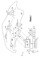
Figure 1 is a schematic illustration of a display system according to an embodiment of the present invention for displaying at least a portion of a representation of an environment; and, -
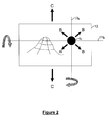
Figure 2 is a schematic illustration of a display window of the display system illustrated infigure 1 . - Referring to the drawings, there is illustrated a display system 10 for displaying a 3-dimensional visual representation of at least a portion of an
environment 100, to an operator (not shown) of a vehicle (not shown). The system 10 may be disposed within a vehicle (not shown) and enables the operator of the vehicle, which may comprise a submersible (not shown), aship 101 or acar 102, to suitably navigate a vehicle across alandscape 103a or upon a lake 103b by providing the operator with environment information in the form of a real-life, intuitive visual representation of theenvironment 100. It is also envisaged however, that the system 10 may be stationed remote to the vehicle being navigated, within a surveillance station (not shown) for example, and thus stationary with respect to the vehicle being navigated. - The system 10 comprises a plurality of sensor modules 11 a, 11 b which are arranged to acquire real-time information on dynamic environmental features, such as the movement of vehicles, sea conditions and the like, in addition to static environmental information such as topography and bathymetry. This information may be obtained from transponders 104, RADAR (Radio Direction And Ranging)
stations 105, video streams from closed circuit television systems (not shown), SONAR (SOund Navigation And Ranging), LIDAR (Llght Detection And Ranging) stations, and the like, in addition to existing charts and plots (not shown) of theenvironment 100. The sensor modules 11 a, 11 b are arranged to retrieve environmental information and output the sensed information to aprocessor 12, which subsequently processes the information and generates the visual representation on adisplay screen 13. The system 10 further comprises a user interface devices, such as akeyboard 14, amouse 15, a joystick (not shown) and the like which enable an operator (not shown) to interact with the system 10 and provide operator commands and input to the system 10. - The
processor 12 is further arranged to overlay areference marker 16 upon the displayed representation so that an operator can select the area of theenvironment 100 to be displayed by suitably positioning thereference marker 16 at the desired location within the representation using an interface device, such as themouse 15. Thereference marker 16 may comprise a "dot" which may be disposed centrally of thedisplay screen 13 or at any other operator specified location within to thedisplay screen 13. - The
marker 16 provides a reference for the operator in selecting the displayed direction relative to the operator (not shown). The displayed direction may be an absolute direction, for example a relocation of the marker at a specified location within the representation to provide an operator with a representation of the selected location. Alternatively, themarker 16 may serve to provide a relative direction, for example a view of the selected location from a different viewpoint from within the representation and in this case, themarker 16 is arranged to remain at a fixed position, namely locked, within thedisplay screen 13, for each viewpoint. - In the case of a change in absolute direction, the
display 13 will provide an apparent motion to the operator as the operator slides themarker 16 across the representation of theenvironment 100, as illustrated by arrows B infigure 2 of the drawings. In this case, the system 10 is arranged to operate in one of two modes. In the first mode, themarker 16 is arranged to remain at a selected altitude above or below sea level, as long as the terrain/bathymetry permits, whereas in the second mode, themarker 16 is arranged to remain at a selected altitude above the terrain/bathymetry, and is arranged to follow the contour of the terrain to maintain this altitude as themarker 16 moves across the terrain. - In the case of a change in the relative direction, the
marker 16 is arranged to remain at a fixed location within the representation and provides a reference about which thedisplay 13 can pivot to provide a view of the location from all positions around the location. For example, upon positioning the marker upon the hull of aship 101, then the display system 10 can provide a view from all around theship 101 from below the hull to above the hull, and thus enable a ship pilot for example, to determine whether there is sufficient water depth to manoeuvre within a harbour (not shown). This change in relative direction is achieved by combining a change in viewing altitude with respect to the representation, as illustrated with arrow C-C, with a rotation of the displayed view about a vertical and/orhorizontal axis 17a, 17b which extend within thedisplay screen 13 and which extend through the marker 16 (as illustrated infigure 2 of the drawings). - In addition, the operator (not shown) can adjust the apparent separation of the
display 13 from the marked location (as indicated by arrow A-A) to reduce the separation to obtain a magnified view of the location, and thus obtain a detailed representation of the location, as indicated by thedisplay portion 13a. Alternatively, the operator may increase the apparent separation to obtain a more global view of the location, as indicated by the display portion 13b. - The system further comprises an
optimisation module 18 for optimising the visual representation of theenvironment 100 in dependence of the sensed information and operator input commands, for example the operator specified viewing direction. For example, theoptimisation module 18 may be arranged to restrict the rotation of the viewing direction about the horizontal axis 17b in accordance with the apparent separation of thedisplay screen 13 from the location, to prevent the viewing direction falling from below the terrain surface. As a further example, the optimisation module may be arranged to increase the apparent size of environmental objects as an operator zooms out from a location within the representation, so that the objects remain visible to the operator. This may be further supplemented with a change in the colour of displayed objects, for example. - The system 10 further comprises a
surveillance module 19 for providing real-time information on the separation of the objects, such as obstacles and vehicles, within theenvironment 100 to alert the operator to potential collision hazards, for example. Similarly, the system 10 further comprises an automated surveillance module which allows for an automated navigation and operation of a vehicle (not shown) within the surveyedenvironment 100 without the need for any active input from the operator. If required, the system 10 may communicate the information from the sensor andsurveillance modules 11, 19, 20, using acommunication device 21, to enable a remote operation of the vehicle. - In order to provide more intuitive representation of the visual representation of the environment, the system is further arranged to selectively populate the display with a plurality of groups of environmental objects, such as marine buoys, and vehicles (not shown) proximate to the vehicle (not shown) being manoeuvred.
- From the foregoing therefore, it is evident that the display system provides for an improved manoeuvrability and navigation of vehicles, through the provision of an intuitive visual representation of the environment.
Claims (15)
- A display system for providing a visual representation of an environment, the system comprising a processor which is arranged to receive information of the environment from at least one environment sensor and output display signals representative of the sensed information to a display device,
the display device comprising a display window, which is arranged to display at least a portion of said representation,
the display device being further arranged to display a display reference at a fixed location within said representation,
wherein said display window is further arranged to selectively display said portion from one of a plurality of viewpoints from within said representation, each viewpoint comprising the display reference at a fixed location within said window and within said representation. - A display system according to claim 1, wherein the display device is arranged to display a 3-dimensional representation of the environment.
- A display system according to claim 1 or 2, wherein said display reference is selectably positioned within said representation by a user.
- A display system according to claim 3, wherein the display window is arranged to follow the topography/bathymetry of the representation of the environment as the user navigates the display reference within the representation.
- A display system according to any preceding claim, wherein the display reference is selectably positioned or further positioned within said window by a user.
- A display system according to any preceding claim, wherein the display window is rotatable with respect to the representation about an axis comprising the display reference, so that a user can steer the display direction.
- A display system according to any preceding claim, wherein a visual separation of the display window from the display reference within said representation is variable.
- A display system according to any preceding claim, wherein the display portion is selectable by a user by re-positioning the display reference within the visual representation of the environment.
- A display system according to any preceding claim, wherein the display system is arranged or further arranged to selectively display at least one group of environment features.
- A display system according to any preceding claim, further comprising a plurality of sensor modules, which are arranged to acquire information from the at least one environment sensor.
- A display system according to any preceding claim, further comprising a user interface for enabling a user to input commands to the system.
- A display system according to claims 10 and 11, further comprising optimisation modules for optimising the visual representation of the environment, in accordance with the information acquired from the sensor modules and user input commands.
- A display system according to any preceding claim, further comprising surveillance modules which are arranged to maintain real-time spatial relationships between objects within the representation and alert a user to potential dangers in the environment.
- A display system according to any preceding claim, further comprising an automated surveillance module which enables a passive surveillance of the environment without requiring any active analysis by the user.
- A display system according to claims 10 and 13, further comprising communication means for communicating sensor and/or surveillance information to remote locations.
Applications Claiming Priority (1)
| Application Number | Priority Date | Filing Date | Title |
|---|---|---|---|
| GB1105454.1A GB2489685B (en) | 2011-03-31 | 2011-03-31 | A Display System |
Publications (3)
| Publication Number | Publication Date |
|---|---|
| EP2506220A2 true EP2506220A2 (en) | 2012-10-03 |
| EP2506220A3 EP2506220A3 (en) | 2017-02-22 |
| EP2506220B1 EP2506220B1 (en) | 2019-01-23 |
Family
ID=44071728
Family Applications (1)
| Application Number | Title | Priority Date | Filing Date |
|---|---|---|---|
| EP12160278.3A Active EP2506220B1 (en) | 2011-03-31 | 2012-03-20 | A display system |
Country Status (3)
| Country | Link |
|---|---|
| US (1) | US10235804B2 (en) |
| EP (1) | EP2506220B1 (en) |
| GB (1) | GB2489685B (en) |
Family Cites Families (30)
| Publication number | Priority date | Publication date | Assignee | Title |
|---|---|---|---|---|
| US5583972A (en) * | 1993-08-02 | 1996-12-10 | Miller; Richard L. | 3-D weather display and weathercast system |
| US5781146A (en) * | 1996-03-11 | 1998-07-14 | Imaging Accessories, Inc. | Automatic horizontal and vertical scanning radar with terrain display |
| US20030210228A1 (en) * | 2000-02-25 | 2003-11-13 | Ebersole John Franklin | Augmented reality situational awareness system and method |
| US20020180809A1 (en) * | 2001-05-31 | 2002-12-05 | Light John J. | Navigation in rendered three-dimensional spaces |
| US7274380B2 (en) * | 2001-10-04 | 2007-09-25 | Siemens Corporate Research, Inc. | Augmented reality system |
| US6917370B2 (en) * | 2002-05-13 | 2005-07-12 | Charles Benton | Interacting augmented reality and virtual reality |
| US8363144B2 (en) * | 2003-12-18 | 2013-01-29 | Anthrotronix, Inc. | Operator control unit with tracking |
| US7382374B2 (en) * | 2005-05-02 | 2008-06-03 | Bitplane Ag | Computerized method and computer system for positioning a pointer |
| ATE393427T1 (en) * | 2005-05-02 | 2008-05-15 | Bitplane Ag | COMPUTER-ASSISTED METHOD AND COMPUTER SYSTEM FOR POSITIONING A POINTER |
| US10198521B2 (en) * | 2005-06-27 | 2019-02-05 | Google Llc | Processing ambiguous search requests in a geographic information system |
| WO2007046063A2 (en) * | 2005-10-21 | 2007-04-26 | Koninklijke Philips Electronics N.V. | A method of and a system for interactive probing and annotating medical images using profile flags |
| US20080033641A1 (en) * | 2006-07-25 | 2008-02-07 | Medalia Michael J | Method of generating a three-dimensional interactive tour of a geographic location |
| US20080192118A1 (en) * | 2006-09-22 | 2008-08-14 | Rimbold Robert K | Three-Dimensional Surveillance Toolkit |
| US8994851B2 (en) * | 2007-08-07 | 2015-03-31 | Qualcomm Incorporated | Displaying image data and geographic element data |
| US8314789B2 (en) * | 2007-09-26 | 2012-11-20 | Autodesk, Inc. | Navigation system for a 3D virtual scene |
| US8099234B1 (en) * | 2008-07-03 | 2012-01-17 | Rockwell Collins, Inc. | System, apparatus, and method for generating location information on an aircraft display unit using location markers |
| WO2010019205A1 (en) * | 2008-08-12 | 2010-02-18 | Google Inc. | Touring in a geographic information system |
| US9310992B2 (en) * | 2008-08-22 | 2016-04-12 | Google Inc. | Panning in a three dimensional environment on a mobile device |
| US20100131126A1 (en) * | 2008-11-21 | 2010-05-27 | Honeywell International Inc. | System and display element for displaying waypoint markers with integrated altitude constraint information |
| US8294766B2 (en) * | 2009-01-28 | 2012-10-23 | Apple Inc. | Generating a three-dimensional model using a portable electronic device recording |
| US8566020B2 (en) * | 2009-12-01 | 2013-10-22 | Nokia Corporation | Method and apparatus for transforming three-dimensional map objects to present navigation information |
| US20110137561A1 (en) * | 2009-12-04 | 2011-06-09 | Nokia Corporation | Method and apparatus for measuring geographic coordinates of a point of interest in an image |
| US9164577B2 (en) * | 2009-12-22 | 2015-10-20 | Ebay Inc. | Augmented reality system, method, and apparatus for displaying an item image in a contextual environment |
| US8400548B2 (en) * | 2010-01-05 | 2013-03-19 | Apple Inc. | Synchronized, interactive augmented reality displays for multifunction devices |
| US8436872B2 (en) * | 2010-02-03 | 2013-05-07 | Oculus Info Inc. | System and method for creating and displaying map projections related to real-time images |
| WO2011106520A1 (en) * | 2010-02-24 | 2011-09-01 | Ipplex Holdings Corporation | Augmented reality panorama supporting visually impaired individuals |
| JP2011244058A (en) * | 2010-05-14 | 2011-12-01 | Sony Corp | Information processing device, information processing system, and program |
| US20110279446A1 (en) * | 2010-05-16 | 2011-11-17 | Nokia Corporation | Method and apparatus for rendering a perspective view of objects and content related thereto for location-based services on mobile device |
| US9710554B2 (en) * | 2010-09-23 | 2017-07-18 | Nokia Technologies Oy | Methods, apparatuses and computer program products for grouping content in augmented reality |
| US9147221B2 (en) * | 2012-05-23 | 2015-09-29 | Qualcomm Incorporated | Image-driven view management for annotations |
-
2011
- 2011-03-31 GB GB1105454.1A patent/GB2489685B/en active Active
-
2012
- 2012-03-20 EP EP12160278.3A patent/EP2506220B1/en active Active
- 2012-03-27 US US13/430,719 patent/US10235804B2/en active Active
Non-Patent Citations (1)
| Title |
|---|
| None |
Also Published As
| Publication number | Publication date |
|---|---|
| US20120249786A1 (en) | 2012-10-04 |
| GB2489685A (en) | 2012-10-10 |
| GB2489685B (en) | 2017-01-25 |
| EP2506220A3 (en) | 2017-02-22 |
| US10235804B2 (en) | 2019-03-19 |
| EP2506220B1 (en) | 2019-01-23 |
| GB201105454D0 (en) | 2011-05-18 |
Similar Documents
| Publication | Publication Date | Title |
|---|---|---|
| US12066579B2 (en) | Real-time monitoring of surroundings of marine vessel | |
| US20250196977A1 (en) | Video sensor fusion and model based virtual and augmented reality systems and methods | |
| US11892298B2 (en) | Navigational danger identification and feedback systems and methods | |
| US10942028B2 (en) | Video sensor fusion and model based virtual and augmented reality systems and methods | |
| US11328155B2 (en) | Augmented reality labels systems and methods | |
| US10338800B2 (en) | Enhanced pilot display systems and methods | |
| EP3125213B1 (en) | Onboard aircraft systems and methods to identify moving landing platforms | |
| US7375678B2 (en) | Displaying obstacles in perspective view | |
| US10431099B2 (en) | Collision avoidance systems and methods | |
| EP3082121B1 (en) | Aircraft systems and methods to display moving landing platforms | |
| JP7255794B2 (en) | Disturbance zone determination method, mobile system and disturbance zone display method | |
| KR20220079667A (en) | Shipbuilding support systems and methods | |
| JP2015215278A (en) | Information display device | |
| KR20130121744A (en) | Device and method for displaying information | |
| JP2015215532A (en) | Information display device | |
| US20110025684A1 (en) | Three-dimensional tactical display and method for visualizing data with a probability of uncertainty | |
| WO2018102772A1 (en) | System and method for augmented reality comprising labels | |
| EP2506220B1 (en) | A display system | |
| US10094912B2 (en) | Operator terminal with display of zones of picture taking quality |
Legal Events
| Date | Code | Title | Description |
|---|---|---|---|
| PUAI | Public reference made under article 153(3) epc to a published international application that has entered the european phase |
Free format text: ORIGINAL CODE: 0009012 |
|
| AK | Designated contracting states |
Kind code of ref document: A2 Designated state(s): AL AT BE BG CH CY CZ DE DK EE ES FI FR GB GR HR HU IE IS IT LI LT LU LV MC MK MT NL NO PL PT RO RS SE SI SK SM TR |
|
| AX | Request for extension of the european patent |
Extension state: BA ME |
|
| PUAL | Search report despatched |
Free format text: ORIGINAL CODE: 0009013 |
|
| AK | Designated contracting states |
Kind code of ref document: A3 Designated state(s): AL AT BE BG CH CY CZ DE DK EE ES FI FR GB GR HR HU IE IS IT LI LT LU LV MC MK MT NL NO PL PT RO RS SE SI SK SM TR |
|
| AX | Request for extension of the european patent |
Extension state: BA ME |
|
| RIC1 | Information provided on ipc code assigned before grant |
Ipc: G06F 3/048 20130101ALI20170118BHEP Ipc: G06T 15/00 20110101ALN20170118BHEP Ipc: G01C 21/36 20060101ALI20170118BHEP Ipc: G06T 19/00 20110101AFI20170118BHEP |
|
| STAA | Information on the status of an ep patent application or granted ep patent |
Free format text: STATUS: REQUEST FOR EXAMINATION WAS MADE |
|
| 17P | Request for examination filed |
Effective date: 20170822 |
|
| RBV | Designated contracting states (corrected) |
Designated state(s): AL AT BE BG CH CY CZ DE DK EE ES FI FR GB GR HR HU IE IS IT LI LT LU LV MC MK MT NL NO PL PT RO RS SE SI SK SM TR |
|
| STAA | Information on the status of an ep patent application or granted ep patent |
Free format text: STATUS: EXAMINATION IS IN PROGRESS |
|
| 17Q | First examination report despatched |
Effective date: 20171019 |
|
| RAP1 | Party data changed (applicant data changed or rights of an application transferred) |
Owner name: SRT MARINE SYSTEM SOLUTIONS LIMITED |
|
| GRAP | Despatch of communication of intention to grant a patent |
Free format text: ORIGINAL CODE: EPIDOSNIGR1 |
|
| STAA | Information on the status of an ep patent application or granted ep patent |
Free format text: STATUS: GRANT OF PATENT IS INTENDED |
|
| RIC1 | Information provided on ipc code assigned before grant |
Ipc: G06T 19/00 20110101AFI20180802BHEP Ipc: G01C 21/36 20060101ALI20180802BHEP Ipc: G06F 3/0481 20130101ALI20180802BHEP |
|
| INTG | Intention to grant announced |
Effective date: 20180830 |
|
| GRAS | Grant fee paid |
Free format text: ORIGINAL CODE: EPIDOSNIGR3 |
|
| GRAA | (expected) grant |
Free format text: ORIGINAL CODE: 0009210 |
|
| STAA | Information on the status of an ep patent application or granted ep patent |
Free format text: STATUS: THE PATENT HAS BEEN GRANTED |
|
| AK | Designated contracting states |
Kind code of ref document: B1 Designated state(s): AL AT BE BG CH CY CZ DE DK EE ES FI FR GR HR HU IE IS IT LI LT LU LV MC MK MT NL NO PL PT RO RS SE SI SK SM TR |
|
| RBV | Designated contracting states (corrected) |
Designated state(s): AL AT BE BG CH CY CZ DE DK EE ES FI FR GR HR HU IE IS IT LI LT LU LV MC MK MT NL NO PL PT RO RS SE SI SK SM TR |
|
| REG | Reference to a national code |
Ref country code: CH Ref legal event code: EP |
|
| RIC2 | Information provided on ipc code assigned after grant |
Ipc: G01C 21/36 20060101ALI20180802BHEP Ipc: G06T 19/00 20110101AFI20180802BHEP Ipc: G06F 3/0481 20130101ALI20180802BHEP |
|
| REG | Reference to a national code |
Ref country code: AT Ref legal event code: REF Ref document number: 1092069 Country of ref document: AT Kind code of ref document: T Effective date: 20190215 |
|
| REG | Reference to a national code |
Ref country code: IE Ref legal event code: FG4D |
|
| REG | Reference to a national code |
Ref country code: DE Ref legal event code: R096 Ref document number: 602012056139 Country of ref document: DE |
|
| REG | Reference to a national code |
Ref country code: SE Ref legal event code: TRGR |
|
| REG | Reference to a national code |
Ref country code: NL Ref legal event code: MP Effective date: 20190123 |
|
| PG25 | Lapsed in a contracting state [announced via postgrant information from national office to epo] |
Ref country code: NL Free format text: LAPSE BECAUSE OF FAILURE TO SUBMIT A TRANSLATION OF THE DESCRIPTION OR TO PAY THE FEE WITHIN THE PRESCRIBED TIME-LIMIT Effective date: 20190123 |
|
| PG25 | Lapsed in a contracting state [announced via postgrant information from national office to epo] |
Ref country code: FI Free format text: LAPSE BECAUSE OF FAILURE TO SUBMIT A TRANSLATION OF THE DESCRIPTION OR TO PAY THE FEE WITHIN THE PRESCRIBED TIME-LIMIT Effective date: 20190123 Ref country code: LT Free format text: LAPSE BECAUSE OF FAILURE TO SUBMIT A TRANSLATION OF THE DESCRIPTION OR TO PAY THE FEE WITHIN THE PRESCRIBED TIME-LIMIT Effective date: 20190123 Ref country code: PL Free format text: LAPSE BECAUSE OF FAILURE TO SUBMIT A TRANSLATION OF THE DESCRIPTION OR TO PAY THE FEE WITHIN THE PRESCRIBED TIME-LIMIT Effective date: 20190123 Ref country code: PT Free format text: LAPSE BECAUSE OF FAILURE TO SUBMIT A TRANSLATION OF THE DESCRIPTION OR TO PAY THE FEE WITHIN THE PRESCRIBED TIME-LIMIT Effective date: 20190523 Ref country code: NO Free format text: LAPSE BECAUSE OF FAILURE TO SUBMIT A TRANSLATION OF THE DESCRIPTION OR TO PAY THE FEE WITHIN THE PRESCRIBED TIME-LIMIT Effective date: 20190423 Ref country code: ES Free format text: LAPSE BECAUSE OF FAILURE TO SUBMIT A TRANSLATION OF THE DESCRIPTION OR TO PAY THE FEE WITHIN THE PRESCRIBED TIME-LIMIT Effective date: 20190123 |
|
| REG | Reference to a national code |
Ref country code: AT Ref legal event code: MK05 Ref document number: 1092069 Country of ref document: AT Kind code of ref document: T Effective date: 20190123 |
|
| PG25 | Lapsed in a contracting state [announced via postgrant information from national office to epo] |
Ref country code: BG Free format text: LAPSE BECAUSE OF FAILURE TO SUBMIT A TRANSLATION OF THE DESCRIPTION OR TO PAY THE FEE WITHIN THE PRESCRIBED TIME-LIMIT Effective date: 20190423 Ref country code: GR Free format text: LAPSE BECAUSE OF FAILURE TO SUBMIT A TRANSLATION OF THE DESCRIPTION OR TO PAY THE FEE WITHIN THE PRESCRIBED TIME-LIMIT Effective date: 20190424 Ref country code: HR Free format text: LAPSE BECAUSE OF FAILURE TO SUBMIT A TRANSLATION OF THE DESCRIPTION OR TO PAY THE FEE WITHIN THE PRESCRIBED TIME-LIMIT Effective date: 20190123 Ref country code: RS Free format text: LAPSE BECAUSE OF FAILURE TO SUBMIT A TRANSLATION OF THE DESCRIPTION OR TO PAY THE FEE WITHIN THE PRESCRIBED TIME-LIMIT Effective date: 20190123 Ref country code: LV Free format text: LAPSE BECAUSE OF FAILURE TO SUBMIT A TRANSLATION OF THE DESCRIPTION OR TO PAY THE FEE WITHIN THE PRESCRIBED TIME-LIMIT Effective date: 20190123 Ref country code: IS Free format text: LAPSE BECAUSE OF FAILURE TO SUBMIT A TRANSLATION OF THE DESCRIPTION OR TO PAY THE FEE WITHIN THE PRESCRIBED TIME-LIMIT Effective date: 20190523 |
|
| REG | Reference to a national code |
Ref country code: DE Ref legal event code: R097 Ref document number: 602012056139 Country of ref document: DE |
|
| PG25 | Lapsed in a contracting state [announced via postgrant information from national office to epo] |
Ref country code: MC Free format text: LAPSE BECAUSE OF FAILURE TO SUBMIT A TRANSLATION OF THE DESCRIPTION OR TO PAY THE FEE WITHIN THE PRESCRIBED TIME-LIMIT Effective date: 20190123 Ref country code: AL Free format text: LAPSE BECAUSE OF FAILURE TO SUBMIT A TRANSLATION OF THE DESCRIPTION OR TO PAY THE FEE WITHIN THE PRESCRIBED TIME-LIMIT Effective date: 20190123 Ref country code: EE Free format text: LAPSE BECAUSE OF FAILURE TO SUBMIT A TRANSLATION OF THE DESCRIPTION OR TO PAY THE FEE WITHIN THE PRESCRIBED TIME-LIMIT Effective date: 20190123 Ref country code: DK Free format text: LAPSE BECAUSE OF FAILURE TO SUBMIT A TRANSLATION OF THE DESCRIPTION OR TO PAY THE FEE WITHIN THE PRESCRIBED TIME-LIMIT Effective date: 20190123 Ref country code: IT Free format text: LAPSE BECAUSE OF FAILURE TO SUBMIT A TRANSLATION OF THE DESCRIPTION OR TO PAY THE FEE WITHIN THE PRESCRIBED TIME-LIMIT Effective date: 20190123 Ref country code: RO Free format text: LAPSE BECAUSE OF FAILURE TO SUBMIT A TRANSLATION OF THE DESCRIPTION OR TO PAY THE FEE WITHIN THE PRESCRIBED TIME-LIMIT Effective date: 20190123 Ref country code: CZ Free format text: LAPSE BECAUSE OF FAILURE TO SUBMIT A TRANSLATION OF THE DESCRIPTION OR TO PAY THE FEE WITHIN THE PRESCRIBED TIME-LIMIT Effective date: 20190123 Ref country code: SK Free format text: LAPSE BECAUSE OF FAILURE TO SUBMIT A TRANSLATION OF THE DESCRIPTION OR TO PAY THE FEE WITHIN THE PRESCRIBED TIME-LIMIT Effective date: 20190123 |
|
| REG | Reference to a national code |
Ref country code: CH Ref legal event code: PL |
|
| PG25 | Lapsed in a contracting state [announced via postgrant information from national office to epo] |
Ref country code: SM Free format text: LAPSE BECAUSE OF FAILURE TO SUBMIT A TRANSLATION OF THE DESCRIPTION OR TO PAY THE FEE WITHIN THE PRESCRIBED TIME-LIMIT Effective date: 20190123 Ref country code: LU Free format text: LAPSE BECAUSE OF NON-PAYMENT OF DUE FEES Effective date: 20190320 |
|
| PLBE | No opposition filed within time limit |
Free format text: ORIGINAL CODE: 0009261 |
|
| STAA | Information on the status of an ep patent application or granted ep patent |
Free format text: STATUS: NO OPPOSITION FILED WITHIN TIME LIMIT |
|
| PG25 | Lapsed in a contracting state [announced via postgrant information from national office to epo] |
Ref country code: AT Free format text: LAPSE BECAUSE OF FAILURE TO SUBMIT A TRANSLATION OF THE DESCRIPTION OR TO PAY THE FEE WITHIN THE PRESCRIBED TIME-LIMIT Effective date: 20190123 |
|
| 26N | No opposition filed |
Effective date: 20191024 |
|
| PG25 | Lapsed in a contracting state [announced via postgrant information from national office to epo] |
Ref country code: LI Free format text: LAPSE BECAUSE OF NON-PAYMENT OF DUE FEES Effective date: 20190331 Ref country code: IE Free format text: LAPSE BECAUSE OF NON-PAYMENT OF DUE FEES Effective date: 20190320 Ref country code: CH Free format text: LAPSE BECAUSE OF NON-PAYMENT OF DUE FEES Effective date: 20190331 |
|
| PG25 | Lapsed in a contracting state [announced via postgrant information from national office to epo] |
Ref country code: SI Free format text: LAPSE BECAUSE OF FAILURE TO SUBMIT A TRANSLATION OF THE DESCRIPTION OR TO PAY THE FEE WITHIN THE PRESCRIBED TIME-LIMIT Effective date: 20190123 |
|
| PG25 | Lapsed in a contracting state [announced via postgrant information from national office to epo] |
Ref country code: TR Free format text: LAPSE BECAUSE OF FAILURE TO SUBMIT A TRANSLATION OF THE DESCRIPTION OR TO PAY THE FEE WITHIN THE PRESCRIBED TIME-LIMIT Effective date: 20190123 |
|
| PG25 | Lapsed in a contracting state [announced via postgrant information from national office to epo] |
Ref country code: MT Free format text: LAPSE BECAUSE OF NON-PAYMENT OF DUE FEES Effective date: 20190320 |
|
| PG25 | Lapsed in a contracting state [announced via postgrant information from national office to epo] |
Ref country code: CY Free format text: LAPSE BECAUSE OF FAILURE TO SUBMIT A TRANSLATION OF THE DESCRIPTION OR TO PAY THE FEE WITHIN THE PRESCRIBED TIME-LIMIT Effective date: 20190123 |
|
| PG25 | Lapsed in a contracting state [announced via postgrant information from national office to epo] |
Ref country code: HU Free format text: LAPSE BECAUSE OF FAILURE TO SUBMIT A TRANSLATION OF THE DESCRIPTION OR TO PAY THE FEE WITHIN THE PRESCRIBED TIME-LIMIT; INVALID AB INITIO Effective date: 20120320 |
|
| PG25 | Lapsed in a contracting state [announced via postgrant information from national office to epo] |
Ref country code: MK Free format text: LAPSE BECAUSE OF FAILURE TO SUBMIT A TRANSLATION OF THE DESCRIPTION OR TO PAY THE FEE WITHIN THE PRESCRIBED TIME-LIMIT Effective date: 20190123 |
|
| PGFP | Annual fee paid to national office [announced via postgrant information from national office to epo] |
Ref country code: DE Payment date: 20250331 Year of fee payment: 14 |
|
| PGFP | Annual fee paid to national office [announced via postgrant information from national office to epo] |
Ref country code: SE Payment date: 20260327 Year of fee payment: 15 |
|
| PGFP | Annual fee paid to national office [announced via postgrant information from national office to epo] |
Ref country code: BE Payment date: 20260324 Year of fee payment: 15 |
|
| PGFP | Annual fee paid to national office [announced via postgrant information from national office to epo] |
Ref country code: FR Payment date: 20260327 Year of fee payment: 15 |