EP2505946A1 - Air cooled refrigerator, control method and control system thereof - Google Patents
Air cooled refrigerator, control method and control system thereof Download PDFInfo
- Publication number
- EP2505946A1 EP2505946A1 EP10848752A EP10848752A EP2505946A1 EP 2505946 A1 EP2505946 A1 EP 2505946A1 EP 10848752 A EP10848752 A EP 10848752A EP 10848752 A EP10848752 A EP 10848752A EP 2505946 A1 EP2505946 A1 EP 2505946A1
- Authority
- EP
- European Patent Office
- Prior art keywords
- refrigerating
- temperature
- evaporator
- rotating speed
- fan
- Prior art date
- Legal status (The legal status is an assumption and is not a legal conclusion. Google has not performed a legal analysis and makes no representation as to the accuracy of the status listed.)
- Granted
Links
Images



Classifications
-
- F—MECHANICAL ENGINEERING; LIGHTING; HEATING; WEAPONS; BLASTING
- F25—REFRIGERATION OR COOLING; COMBINED HEATING AND REFRIGERATION SYSTEMS; HEAT PUMP SYSTEMS; MANUFACTURE OR STORAGE OF ICE; LIQUEFACTION SOLIDIFICATION OF GASES
- F25D—REFRIGERATORS; COLD ROOMS; ICE-BOXES; COOLING OR FREEZING APPARATUS NOT OTHERWISE PROVIDED FOR
- F25D17/00—Arrangements for circulating cooling fluids; Arrangements for circulating gas, e.g. air, within refrigerated spaces
- F25D17/04—Arrangements for circulating cooling fluids; Arrangements for circulating gas, e.g. air, within refrigerated spaces for circulating air, e.g. by convection
- F25D17/06—Arrangements for circulating cooling fluids; Arrangements for circulating gas, e.g. air, within refrigerated spaces for circulating air, e.g. by convection by forced circulation
- F25D17/062—Arrangements for circulating cooling fluids; Arrangements for circulating gas, e.g. air, within refrigerated spaces for circulating air, e.g. by convection by forced circulation in household refrigerators
- F25D17/065—Arrangements for circulating cooling fluids; Arrangements for circulating gas, e.g. air, within refrigerated spaces for circulating air, e.g. by convection by forced circulation in household refrigerators with compartments at different temperatures
-
- F—MECHANICAL ENGINEERING; LIGHTING; HEATING; WEAPONS; BLASTING
- F25—REFRIGERATION OR COOLING; COMBINED HEATING AND REFRIGERATION SYSTEMS; HEAT PUMP SYSTEMS; MANUFACTURE OR STORAGE OF ICE; LIQUEFACTION SOLIDIFICATION OF GASES
- F25D—REFRIGERATORS; COLD ROOMS; ICE-BOXES; COOLING OR FREEZING APPARATUS NOT OTHERWISE PROVIDED FOR
- F25D29/00—Arrangement or mounting of control or safety devices
-
- F—MECHANICAL ENGINEERING; LIGHTING; HEATING; WEAPONS; BLASTING
- F25—REFRIGERATION OR COOLING; COMBINED HEATING AND REFRIGERATION SYSTEMS; HEAT PUMP SYSTEMS; MANUFACTURE OR STORAGE OF ICE; LIQUEFACTION SOLIDIFICATION OF GASES
- F25B—REFRIGERATION MACHINES, PLANTS OR SYSTEMS; COMBINED HEATING AND REFRIGERATION SYSTEMS; HEAT PUMP SYSTEMS
- F25B2600/00—Control issues
- F25B2600/11—Fan speed control
- F25B2600/112—Fan speed control of evaporator fans
-
- F—MECHANICAL ENGINEERING; LIGHTING; HEATING; WEAPONS; BLASTING
- F25—REFRIGERATION OR COOLING; COMBINED HEATING AND REFRIGERATION SYSTEMS; HEAT PUMP SYSTEMS; MANUFACTURE OR STORAGE OF ICE; LIQUEFACTION SOLIDIFICATION OF GASES
- F25D—REFRIGERATORS; COLD ROOMS; ICE-BOXES; COOLING OR FREEZING APPARATUS NOT OTHERWISE PROVIDED FOR
- F25D2700/00—Means for sensing or measuring; Sensors therefor
- F25D2700/12—Sensors measuring the inside temperature
Definitions
- the present disclosure relates to a method of controlling an air-cooled refrigerator, a system of controlling the air-cooled refrigerator and an air-cooled refrigerator comprising the system, and more particularly to a method of controlling a humidity in a refrigerating compartment of an air-cooled refrigerator, a system of controlling the humidity in the refrigerating compartment of the air-cooled refrigerator and an air-cooled refrigerator comprising the system.
- a single refrigerating system that is, only one evaporator is disposed in a freezing compartment and a fan are used for providing cold air to the freezing compartment and a refrigerating compartment, and the cold air is controlled to enter into the refrigerating compartment by the opening and the closing of a damper.
- a fan used for providing cold air to the freezing compartment and a refrigerating compartment
- the cold air is controlled to enter into the refrigerating compartment by the opening and the closing of a damper.
- the humidity in the refrigerating compartment is very low, moistures in stored food, especially vegetables, fruits, etc., may be easily lost, and the refreshing effect is poor, thus resulting in air drying of an epidermis of the food and loss of nutrients therein.
- an air-cooled frostless refrigerator having two refrigerating systems in which two evaporators are disposed in a refrigerating compartment and a freezing compartment respectively so that airs in the refrigerating compartment and the freezing compartment are circulated separately.
- certain treatment measures are not taken for the evaporators and working conditions of a fan in the refrigerating compartment are not optimized, although factors non-advantageous for a user such as tainting by odors among foods are alleviated, moistures in the refrigerating compartment are frosted on the evaporator and then discharged out of the refrigerator after the frost is heated and defrosted. Therefore, the humidity in the entire refrigerating compartment may not be ensured, and the refreshing time of the food may not be ensured.
- a method of controlling an air-cooled refrigerator, a system of controlling the air-cooled refrigerator and an air-cooled refrigerator comprising the system may need to be provided, which may control the humidity in a refrigerating compartment flexibly, avoid moisture loss in food, and/or improve the refreshing effect by appropriately controlling a refrigerating evaporator and a refrigerating fan.
- a method of controlling an air-cooled refrigerator may be provided.
- the air-cooled refrigerator may comprise a refrigerating compartment, a refrigerating evaporator, and a refrigerating fan for circulating an air between the refrigerating evaporator and the refrigerating compartment.
- the method may comprise steps of: detecting a temperature T L in the refrigerating compartment; determining whether the temperature T L is greater than or equal to a first predetermined temperature T 1 , and starting the refrigerating evaporator to refrigerate the refrigerating compartment and adjusting a rotating speed of the refrigerating fan to r 1 if the temperature T L ⁇ T 1 ; determining whether the temperature T L is less than a second predetermined temperature T 2 if the temperature T L ⁇ T 1 ; stopping the refrigerating evaporator and detecting a temperature T H of the refrigerating evaporator if the temperature T L ⁇ T 2 ; and adjusting the rotating speed of the refrigerating fan according to the temperature T H to adjust a humidity in the refrigerating compartment.
- a separate refrigerating evaporator and a separate refrigerating fan are disposed in the refrigerating compartment.
- the operation of the refrigerating evaporator may be controlled according to the temperature in the refrigerating compartment, and the rotating speed of the refrigerating fan may be adjusted according to the temperature of the refrigerating evaporator appropriately and flexibly, so that a higher humidity in the refrigerating compartment may be maintained, moisture loss of food in the refrigerating compartment may be reduced effectively, and the refreshing effect may be enhanced.
- the defrosting period of the refrigerating compartment may be prolonged, or the total working times of a heating wire in the refrigerating compartment within a time unit may be decreased, thus reducing electric energy consumption.
- first predetermined temperature T 1 is a maximum allowable temperature in the refrigerating compartment
- second predetermined temperature T 2 is a minimum allowable temperature in the refrigerating compartment.
- the step of adjusting the rotating speed of the refrigerating fan comprises decreasing the rotating speed of the refrigerating fan stage by stage with an increase of the temperature T H .
- the step of adjusting the rotating speed of the refrigerating fan further comprises: adjusting the rotating speed of the refrigerating fan to r 2 if T H ⁇ t 3 ; adjusting the rotating speed of the refrigerating fan to r 3 if t 3 ⁇ T H ⁇ t 4 ; and adjusting the rotating speed of the refrigerating fan to r 4 if T H ⁇ t 4 , where t 3 is a third predetermined temperature, t 4 is a fourth predetermined temperature, and r 4 ⁇ r 3 ⁇ r 2 ⁇ r 1 .
- the step of adjusting the rotating speed of the refrigerating fan comprises decreasing the rotating speed of the refrigerating fan gradually with an increase of the temperature T H .
- a system of controlling an air-cooled refrigerator may be provided.
- the air-cooled refrigerator may comprise a refrigerating compartment, a refrigerating evaporator, and a refrigerating fan for circulating an air between the refrigerating evaporator and the refrigerating compartment.
- the system may comprise: a refrigerating compartment temperature detecting unit for detecting a temperature T L in the refrigerating compartment; a refrigerating compartment temperature determining unit for determining whether T 2 ⁇ T L ⁇ T 1 , where T 1 is a first predetermined temperature, and T 2 is a second predetermined temperature; a refrigerating evaporator temperature detecting unit for detecting a temperature T H of the refrigerating evaporator; and a control unit for starting the refrigerating evaporator to refrigerate the refrigerating compartment and adjusting a rotating speed of the refrigerating fan to r 1 if T 1 ⁇ T 1 , and stopping an operation of the refrigerating evaporator and adjusting the rotating speed of the refrigerating fan according to the temperature T H to adjust a humidity in the refrigerating compartment if T L ⁇ T 2 .
- the refrigerating evaporator is controlled by the control unit to continue operating, and the rotating speed of the refrigerating fan is maintained at r 1 .
- the rotating speed of the refrigerating fan is decreased by the control unit stage by stage with an increase of the temperature T H .
- the system may further comprise a refrigerating evaporator temperature determining unit for determining the temperature of the refrigerating evaporator, in which the rotating speed of the refrigerating fan is adjusted to r 2 by the control unit if it is determined by the refrigerating evaporator temperature determining unit that T H ⁇ t 3 , the rotating speed of the refrigerating fan is adjusted to r 3 by the control unit if it is determined by the refrigerating evaporator temperature determining unit that t 3 ⁇ T H ⁇ t 4 , and the rotating speed of the refrigerating fan is adjusted to r 4 by the control unit if it is determined by the refrigerating evaporator temperature determining unit that T H ⁇ t 4 , where t 3 is a third predetermined temperature, t 4 is a fourth predetermined temperature, and r 4 ⁇ r 3 ⁇ r 2 ⁇ r 1 .
- a refrigerating evaporator temperature determining unit for determining the temperature of the
- an air-cooled refrigerator may comprise: a refrigerating compartment; a refrigerating evaporator; and a refrigerating fan for circulating an air between the refrigerating evaporator and the refrigerating compartment, in which the air-cooled refrigerator further comprises a system according to the second aspect of the present disclosure.
- the air-cooled refrigerator according to the third aspect of the present disclosure may further comprise a freezing compartment, a freezing evaporator, and a switching unit, in which the switching unit is connected with the freezing evaporator via a freezing capillary tube, the refrigerating evaporator is connected with the switching unit via a refrigerating capillary tube, the refrigerating evaporator and the refrigerating capillary tube are connected with the freezing capillary tube in parallel, and the switching unit is controlled by the control unit to selectively supply a refrigerant to the refrigerating evaporator, to start or stop the refrigerating of the refrigerating compartment.
- the refrigerating evaporator comprises a coil pipe and a plurality of fins, the coil pipe is extended into a corrugated shape in a longitudinal direction to form a plurality of layers of pipe segments in a lateral direction perpendicular to the longitudinal direction, the plurality of fins are arranged in the lateral direction and connected with the coil pipe respectively, and at least a part of the fins have at least a break point in the longitudinal direction to be discontinuous in the longitudinal direction.
- each fin has a plurality of break points between two adjacent layers of pipe segments.
- each fin is formed with a plurality of via holes through which the plurality of the layers of the pipe segments are penetrated respectively.
- phraseology and terminology used herein with reference to device or element orientation are only used to simplify description of the present invention, and do not alone indicate or imply that the device or element referred to must have or operated in a particular orientation.
- the body 1 defines a refrigerating compartment 5 located in an upper portion thereof and a freezing compartment 7 located in a lower portion thereof.
- a temperature change compartment B may also be disposed between the refrigerating compartment 5 and the freezing compartment 7.
- a refrigerating evaporator 3 is disposed at a back surface (left side in Fig.
- a refrigerating air passage F is disposed between the refrigerating evaporator 3 and the refrigerating compartment 5
- foam materials may be disposed in the refrigerating air passage F
- a refrigerating fan 4 is disposed between the refrigerating air passage F and the refrigerating compartment 5 for transferring a cold air generated in the refrigerating evaporator 3 to the refrigerating compartment 5.
- the temperature change compartment B is also refrigerated by the cold air generated in the refrigerating evaporator 3, however, the present disclosure is not limited to this.
- a freezing evaporator 6 is disposed at a back surface of the freezing compartment 7.
- a compressor 9 is provided at the bottom of the body 1, and a condenser 8 is disposed at the right side of the compressor 9 at the bottom of the body 1.
- the refrigerating evaporator 3 and the freezing evaporator 6 are disposed in one refrigerating system, and the compressor 9, the condenser 8, an anti-condensation tube 12, a drying filter 11, an electromagnetic valve 10 as a switching unit, and the freezing evaporator 6 are connected, in which the electromagnetic valve 10 is connected with the freezing evaporator 6 via a freezing capillary tube 13.
- the electromagnetic valve 10 is also connected with the refrigerating evaporator 3 via a refrigerating capillary tube 14, and the refrigerating evaporator 3 and the refrigerating capillary tube 14 are connected with the freezing capillary tube 13 in parallel.
- the electromagnetic valve 10 is used for supplying a refrigerant to the refrigerating evaporator 3 selectively, thus controlling the refrigerating of the refrigerating compartment 5 selectively.
- the refrigerating compartment 5 and the freezing compartment 7 are refrigerated by individual evaporators respectively, and only one refrigerating system is used, thus decreasing the total number of the members and reducing the cost accordingly.
- the refrigerating evaporator 3 comprises a coil pipe 31 and a plurality of fins 32.
- the coil pipe 31 is extended into a corrugated shape in a longitudinal direction, the vertical direction in Fig. 6 , to form a plurality of layers of pipe segments 311 in the longitudinal direction.
- adjacent layers of the pipe segments 311 are connected with each other via an arcuate transition pipe segment 312 so that two adjacent layers of pipe segments 311 and the arcuate transition pipe segment 312 form into a substantially U shape.
- the plurality of fins 32 are arranged in a lateral direction, i.e. the left-to-right direction in Fig.
- the fins 32 are discontinuous in the longitudinal direction.
- the fact that at least a part of the fins 32 is discontinuous in the longitudinal direction may be achieved by disposing a break point in one integral fin.
- the fins 32 connected on each layer of pipe segment 311 may be individual ones, so that the fins 32 connected with the plurality of layers of pipe segments 311 respectively are discontinuous in the longitudinal direction.
- each fin 32 has a plurality of break points between two adjacent layers of pipe segments 311 in the longitudinal direction, so that each fin 32 is formed by a plurality of segments which are discontinuous in the longitudinal direction.
- each fin 32 is formed with a plurality of via holes (not shown) through which the plurality of the layers of the pipe segments 311 are penetrated respectively so as to connect the plurality of fins 32 with the plurality of the layers of the pipe segments 311 respectively.
- the plurality of fins 32 may be welded to the plurality of the layers of the pipe segments 311 respectively.
- the fins 32 have a structure which is discontinuous in the longitudinal direction, the surface tension of water may be used to form small water drops at a bottom end of each fin 32, thus avoiding loss of moistures caused by flow and accumulation of water drops along conventional fins which are continuous in the longitudinal direction and prolonging the time period during which water drops remain on the refrigerating evaporator 3. Moreover, the small water drops may be brought into the refrigerating compartment 5 by the way of water vapor circulation, so that a higher humidity in the refrigerating compartment 5 may be maintained.
- small water drops generated during defrosting on the plurality of fins 32 may be converted into water vapors and brought into the refrigerating compartment 5 by the refrigerating fan 4, thus reducing loss of moistures in the refrigerating compartment 5 effectively and avoiding the fact that water drops flow downwards quickly along the conventional fins which are continuous in the longitudinal direction and then are accumulated in a water-containing plate in a bottom of the air-cooled refrigerator to be discharged out of the body 1. Therefore, the refrigerating compartment 5 may be in a high-humidity state, moisture loss in food may be reduced, the refreshing time of the food may be prolonged, and the refreshing performance of the refrigerating compartment 5 may be improved significantly.
- the rotating speed of the refrigerating fan 4 may be appropriately and flexibly adjusted according to the temperature of the refrigerating evaporator 3, so that defrosting water on the refrigerating evaporator 3 may be sent into the refrigerating compartment 5 and the humidity in the refrigerating compartment 5 may be maintained.
- the method of controlling the air-cooled refrigerator for maintaining the humidity in the refrigerating compartment 5 comprises the following steps.
- a temperature T L in the refrigerating compartment 5 is detected (step S101).
- step S102 it is determined whether the temperature T L in the refrigerating compartment 5 is greater than or equal to a first predetermined temperature T 1 (step S102). If T L ⁇ T 1 , the refrigerating evaporator 3 is started to refrigerate the refrigerating compartment 5 and a rotating speed of the refrigerating fan 4 is adjusted to r 1 (step S103).
- step S104 it is determined whether the temperature T L is less than a second predetermined temperature T 2 (step S104).
- step S105 If the temperature T L ⁇ T 2 , the refrigerating evaporator 3 is stopped and a temperature T H of the refrigerating evaporator 3 is detected (step S105).
- the rotating speed of the refrigerating fan 4 is adjusted according to the temperature T H of the refrigerating evaporator 3 to adjust a humidity in the refrigerating compartment 5 (step S106).
- the refrigerating evaporator 3 is started to refrigerate the refrigerating compartment 5.
- the refrigerating evaporator 3 is stopped, but the refrigerating fan 4 is not stopped at this time but continues operating to send defrosting water on the surface of the refrigerating evaporator 3 into the refrigerating compartment 5 and adjust the rotating speed of the refrigerating fan 4 according to the temperature of the refrigerating evaporator 3.
- a higher humidity in the refrigerating compartment 5 may be maintained, moisture loss in food in the refrigerating compartment 5 may be reduced, and the refreshing effect may be enhanced.
- frosting on the refrigerating evaporator 3 may be relatively reduced, thus prolonging the defrosting period of the refrigerating compartment 5, that is, decreasing the working times of a heating wire in the refrigerating compartment 5 per time unit. Therefore, electric energy consumption may be reduced, and the effect of saving energy may be achieved.
- the first predetermined temperature T 1 is a maximum allowable temperature in the refrigerating compartment 5, and the second predetermined temperature T 2 is a minimum allowable temperature in the refrigerating compartment 5.
- the first predetermined temperature T 1 may be determined to be 6 Celsius degrees, and the second predetermined temperature T 2 may be 1 Celsius degree.
- T 2 ⁇ T L ⁇ T 1 for example, the temperature in the refrigerating compartment 5 is decreased from T 1 to T 2 , then the refrigerating evaporator 3 continues operating, and the rotating speed of the refrigerating fan 4 is maintained at r 1 , until T L is less than T 2 .
- the operation of the refrigerating evaporator 3 is stopped when T L is less than T 1 .
- the operation of the refrigerating evaporator 3 may also be stopped.
- the step of adjusting the rotating speed of the refrigerating fan 4 comprises decreasing the rotating speed of the refrigerating fan 4 gradually with an increase of the temperature T H .
- the step of adjusting the rotating speed of the refrigerating fan 4 comprises decreasing the rotating speed of the refrigerating fan 4 stage by stage with an increase of the temperature T H .
- the method of controlling the air-cooled refrigerator comprises the following steps.
- a temperature T L in the refrigerating compartment 5 is detected (step S201).
- step S202 it is determined whether the temperature T L in the refrigerating compartment 5 is greater than or equal to a first predetermined temperature T 1 (step S202). If T L ⁇ T 1 , the refrigerating evaporator 3 is started to refrigerate the refrigerating compartment 5 and a rotating speed of the refrigerating fan 4 is adjusted to r 1 (step S203).
- step S204 it is determined whether the temperature T L is less than a second predetermined temperature T 2 (step S204).
- step S205 If the temperature T L ⁇ T 2 , the refrigerating evaporator 3 is stopped and a temperature T H of the refrigerating evaporator 3 is detected (step S205).
- the rotating speed of the refrigerating fan 4 is adjusted according to the temperature T H of the refrigerating evaporator 3 to adjust a humidity in the refrigerating compartment 5. More particularly, it is determined whether T H is less than t 3 (step S2601), and the rotating speed of the refrigerating fan 4 is adjusted to r 2 if T H ⁇ t 3 (step S2602). If T H is not less than t 3 , it is determined whether T H is less than t 4 (step S2603), and the rotating speed of the refrigerating fan 4 is adjusted to r 3 if t 3 ⁇ T H ⁇ t 4 (step S2604).
- T H is not less than t 4 , it is determined that T H ⁇ t 4 (step S2605), and the rotating speed of the refrigerating fan 4 is adjusted to r 4 (step S2606).
- t 3 is a third predetermined temperature
- t 4 is a fourth predetermined temperature
- r 4 ⁇ r 3 ⁇ r 2 ⁇ r 1 is a third predetermined temperature
- the rotating speed of the refrigerating fan 4 is adjusted according to the temperature T H of the refrigerating evaporator 3 stage by stage, in which the temperature T H of the refrigerating evaporator 3 is divided into three stages. It would be appreciated that the present disclosure is not limited to this, and any suitable quantity of stages may be divided according to applications.
- the rotating speed of the refrigerating fan 4 may be adjusted according to the temperature T H of the refrigerating evaporator 3 stage by stage and flexibly, thus ensuring the humidity in the refrigerating compartment 5 and improving the freshness in the refrigerating compartment 5.
- the system of controlling the air-cooled refrigerator comprises a refrigerating compartment temperature detecting unit 18, a refrigerating compartment temperature determining unit 19 connected with the refrigerating compartment temperature detecting unit 18, a refrigerating evaporator temperature detecting unit 20, and a control unit 15.
- the refrigerating compartment temperature detecting unit 18 is, for example, a temperature sensor for detecting a temperature T L in the refrigerating compartment 5.
- the refrigerating compartment temperature determining unit 19 is used for determining whether T 2 ⁇ T L ⁇ T 1 .
- the refrigerating evaporator temperature detecting unit 20 is used for detecting a temperature T H of the refrigerating evaporator 3.
- the control unit 15 is used for starting the refrigerating evaporator 3 to refrigerate the refrigerating compartment 5 and adjusting a rotating speed of the refrigerating fan 4 to r 1 if T L ⁇ T 1 , and stopping an operation of the refrigerating evaporator 3 and adjusting the rotating speed of the refrigerating fan 4 according to the temperature T H to adjust a humidity in the refrigerating compartment 5 if T L ⁇ T 2 .
- control unit 15 may comprise a refrigerating control unit 17 and a refrigerating fan control unit 16.
- the refrigerating control unit 17 is used for controlling the operation and the stopping of the refrigerating evaporator 3, and the refrigerating fan control unit 16 is used for controlling the refrigerating fan 4.
- the refrigerating evaporator 3 is controlled by the control unit 15 to continue operating, and the rotating speed of the refrigerating fan 4 is maintained at r 1 .
- the rotating speed of the refrigerating fan 4 may be decreased by the control unit 15 gradually or stage by stage with an increase of the temperature T H .
- control unit 15 may further comprise a refrigerating evaporator temperature determining unit 21 for determining the temperature T H of the refrigerating evaporator 3.
- the rotating speed of the refrigerating fan 4 is adjusted to r 2 by the control unit 15 if it is determined by the refrigerating evaporator temperature determining unit 21 that T H ⁇ t 3
- the rotating speed of the refrigerating fan 4 is adjusted to r 3 by the control unit 15 if it is determined by the refrigerating evaporator temperature, determining unit 21 that t 3 ⁇ T H ⁇ t 4
- the rotating speed of the refrigerating fan 4 is adjusted to r 4 by the control unit 15 if it is determined by the refrigerating evaporator temperature determining unit 21 that TH ⁇ t 4 , where t 3 is a third predetermined temperature, t 4 is a fourth predetermined temperature, and r 4 ⁇ r 3 ⁇ r 2 ⁇ r 1 .
- the rotating speed of the refrigerating fan 4 may be adjusted according to the temperature of the refrigerating evaporator 3, so that defrosting water on the refrigerating evaporator 3 may be sent into the refrigerating compartment, 5. Therefore, a higher humidity in the refrigerating compartment 5 may be maintained, moisture loss in food in the refrigerating compartment 5 may be reduced, and the refreshing effect may be enhanced. Moreover, frosting on the refrigerating evaporator 3 may be relatively reduced, thus prolonging the defrosting period of the refrigerating compartment 5, that is, decreasing the working times of a heating wire in the refrigerating compartment 5 per time unit. Therefore, electric energy consumption may be reduced, and the effect of saving energy may be achieved.
- control unit 15, the refrigerating compartment temperature determining unit 19 and the refrigerating evaporator temperature determining unit 21 may be separately provided. However, it would be appreciated by those skilled in the art that the control unit 15, the refrigerating compartment temperature determining unit 19 and the refrigerating evaporator temperature determining unit 21 may be integrated in a single chip.
- the air-cooled refrigerator according to an embodiment of the present disclosure may comprise the above-mentioned system.
- the operation of the air-cooled refrigerator according to an embodiment of the present disclosure will be simply described below.
- the compressor 9 is started by the control unit 15, and the refrigerant is switched into the refrigerating capillary tube 14 by the switching unit (electromagnetic valve) 10, flows into the refrigerating evaporator 3 from the refrigerating capillary tube 14, and then flows into the freezing evaporator 6 from the refrigerating evaporator 3, thus refrigerating the refrigerating compartment 5 and the freezing compartment 7.
- the rotating speed of the refrigerating fan 4 is controlled to be r 1 by the control unit 15.
- the refrigerant is switched into the freezing capillary tube 13 by the electromagnetic valve 10 under the control of the control unit 15, and flows into the freezing evaporator 6 to refrigerate the freezing compartment 7. Because no refrigerants flow into the refrigerating evaporator 3, the refrigerating compartment 5 is not refrigerated. When neither the refrigerating compartment 5 nor the freezing compartment 7 needs to be refrigerated, the operation of the compressor 9 is stopped by the control unit 15.
- the temperature T H of the refrigerating evaporator 3 is detected by the refrigerating evaporator temperature detecting unit 20, the rotating speed of the refrigerating fan 4 is adjusted to r 2 by the control unit 15 if T H ⁇ t 3 , the rotating speed of the refrigerating fan 4 is adjusted to r 3 by the control unit 15 if t 3 ⁇ T H ⁇ t 4 , and the rotating speed of the refrigerating fan 4 is adjusted to r 4 by the control unit 15 if T H ⁇ t 4 . Therefore, defrosting water on the refrigerating evaporator 3 may be sent into the refrigerating compartment 5 by the refrigerating fan 4, thus maintaining the humidity and the freshness in the refrigerating compartment 5.
- separate evaporators and separate air passages are disposed in the refrigerating compartment and the freezing compartment of the air-cooled refrigerator respectively, and the working state of the refrigerating fan is adjusted in an appropriate and flexible manner, so that the refrigerating compartment may be in a high-humidity state, moisture loss in food may be reduced, and the refreshing time of the food may be prolonged. Therefore, the refreshing performance of the refrigerating compartment may be improved significantly. Meanwhile, because the refrigerating compartment and the freezing compartment have separate air passage circulation systems, tainting by odors among foods may be avoided, thus further meeting the requirement of the user.
- defrosting water on the refrigerating evaporator 3 may be sent into the refrigerating compartment 5 by the refrigerating fan 4, a higher humidity in the refrigerating compartment 5 may be maintained, moisture loss in food in the refrigerating compartment 5 may be reduced, and the refreshing effect may be enhanced.
- frosting on the refrigerating evaporator 3 may be relatively reduced, thus prolonging the defrosting period of the refrigerating compartment 5, that is, decreasing the working times of a heating wire in the refrigerating compartment 5 per time unit. Therefore, electric energy consumption may be reduced, and the effect of saving energy may be achieved accordingly.
Landscapes
- Engineering & Computer Science (AREA)
- Chemical & Material Sciences (AREA)
- Combustion & Propulsion (AREA)
- Physics & Mathematics (AREA)
- Mechanical Engineering (AREA)
- Thermal Sciences (AREA)
- General Engineering & Computer Science (AREA)
- Cold Air Circulating Systems And Constructional Details In Refrigerators (AREA)
- Devices That Are Associated With Refrigeration Equipment (AREA)
Abstract
Description
- The present disclosure relates to a method of controlling an air-cooled refrigerator, a system of controlling the air-cooled refrigerator and an air-cooled refrigerator comprising the system, and more particularly to a method of controlling a humidity in a refrigerating compartment of an air-cooled refrigerator, a system of controlling the humidity in the refrigerating compartment of the air-cooled refrigerator and an air-cooled refrigerator comprising the system.
- With a conventional air-cooled frostless refrigerator, normally, a single refrigerating system is adopted, that is, only one evaporator is disposed in a freezing compartment and a fan are used for providing cold air to the freezing compartment and a refrigerating compartment, and the cold air is controlled to enter into the refrigerating compartment by the opening and the closing of a damper. However, because there is only one evaporator, almost all the moistures in the refrigerating compartment are brought back to the evaporator in the freezing compartment via air circulation and are frosted, and consequently water needs to be discharged out of the refrigerator by heating and defrosting of a heating wire periodically. Therefore, the humidity in the refrigerating compartment is very low, moistures in stored food, especially vegetables, fruits, etc., may be easily lost, and the refreshing effect is poor, thus resulting in air drying of an epidermis of the food and loss of nutrients therein.
- Accordingly, an air-cooled frostless refrigerator having two refrigerating systems is provided, in which two evaporators are disposed in a refrigerating compartment and a freezing compartment respectively so that airs in the refrigerating compartment and the freezing compartment are circulated separately. However, because certain treatment measures are not taken for the evaporators and working conditions of a fan in the refrigerating compartment are not optimized, although factors non-advantageous for a user such as tainting by odors among foods are alleviated, moistures in the refrigerating compartment are frosted on the evaporator and then discharged out of the refrigerator after the frost is heated and defrosted. Therefore, the humidity in the entire refrigerating compartment may not be ensured, and the refreshing time of the food may not be ensured.
- The present disclosure is directed to solve at least one of the problems existing in the prior art. Accordingly, a method of controlling an air-cooled refrigerator, a system of controlling the air-cooled refrigerator and an air-cooled refrigerator comprising the system may need to be provided, which may control the humidity in a refrigerating compartment flexibly, avoid moisture loss in food, and/or improve the refreshing effect by appropriately controlling a refrigerating evaporator and a refrigerating fan.
- According to a first aspect of the present disclosure, a method of controlling an air-cooled refrigerator may be provided. The air-cooled refrigerator may comprise a refrigerating compartment, a refrigerating evaporator, and a refrigerating fan for circulating an air between the refrigerating evaporator and the refrigerating compartment. The method may comprise steps of: detecting a temperature TL in the refrigerating compartment; determining whether the temperature TL is greater than or equal to a first predetermined temperature T1, and starting the refrigerating evaporator to refrigerate the refrigerating compartment and adjusting a rotating speed of the refrigerating fan to r1 if the temperature TL≥T1; determining whether the temperature TL is less than a second predetermined temperature T2 if the temperature TL<T1; stopping the refrigerating evaporator and detecting a temperature TH of the refrigerating evaporator if the temperature TL<T2; and adjusting the rotating speed of the refrigerating fan according to the temperature TH to adjust a humidity in the refrigerating compartment.
- With the method of controlling the air-cooled refrigerator according to an embodiment of the present disclosure, a separate refrigerating evaporator and a separate refrigerating fan are disposed in the refrigerating compartment. The operation of the refrigerating evaporator may be controlled according to the temperature in the refrigerating compartment, and the rotating speed of the refrigerating fan may be adjusted according to the temperature of the refrigerating evaporator appropriately and flexibly, so that a higher humidity in the refrigerating compartment may be maintained, moisture loss of food in the refrigerating compartment may be reduced effectively, and the refreshing effect may be enhanced.
- With the method of controlling the air-cooled refrigerator according to an embodiment of the present disclosure, most of defrosting water on the refrigerating evaporator may be brought into the refrigerating compartment, so that frosting on the refrigerating evaporator may be relatively reduced. Therefore, the defrosting period of the refrigerating compartment may be prolonged, or the total working times of a heating wire in the refrigerating compartment within a time unit may be decreased, thus reducing electric energy consumption.
- Further, the first predetermined temperature T1 is a maximum allowable temperature in the refrigerating compartment, and the second predetermined temperature T2 is a minimum allowable temperature in the refrigerating compartment.
- Alternatively, if T2≤TL<T1, the refrigerating evaporator continues operating, and the rotating speed of the refrigerating fan is maintained at r1.
- Further, the step of adjusting the rotating speed of the refrigerating fan comprises decreasing the rotating speed of the refrigerating fan stage by stage with an increase of the temperature TH.
- Particularly, the step of adjusting the rotating speed of the refrigerating fan further comprises: adjusting the rotating speed of the refrigerating fan to r2 if TH<t3; adjusting the rotating speed of the refrigerating fan to r3 if t3≤TH<t4; and adjusting the rotating speed of the refrigerating fan to r4 if TH≥t4, where t3 is a third predetermined temperature, t4 is a fourth predetermined temperature, and r4 < r3 < r2 < r1.
- Alternatively, the step of adjusting the rotating speed of the refrigerating fan comprises decreasing the rotating speed of the refrigerating fan gradually with an increase of the temperature TH.
- According to a second aspect of the present disclosure, a system of controlling an air-cooled refrigerator may be provided. The air-cooled refrigerator may comprise a refrigerating compartment, a refrigerating evaporator, and a refrigerating fan for circulating an air between the refrigerating evaporator and the refrigerating compartment. The system may comprise: a refrigerating compartment temperature detecting unit for detecting a temperature TL in the refrigerating compartment; a refrigerating compartment temperature determining unit for determining whether T2≤TL< T1, where T1 is a first predetermined temperature, and T2 is a second predetermined temperature; a refrigerating evaporator temperature detecting unit for detecting a temperature TH of the refrigerating evaporator; and a control unit for starting the refrigerating evaporator to refrigerate the refrigerating compartment and adjusting a rotating speed of the refrigerating fan to r1 if T1≥T1, and stopping an operation of the refrigerating evaporator and adjusting the rotating speed of the refrigerating fan according to the temperature TH to adjust a humidity in the refrigerating compartment if TL<T2.
- Alternatively, if T2≤TL<T1, the refrigerating evaporator is controlled by the control unit to continue operating, and the rotating speed of the refrigerating fan is maintained at r1.
- Further, the rotating speed of the refrigerating fan is decreased by the control unit stage by stage with an increase of the temperature TH.
- Particularly, the system may further comprise a refrigerating evaporator temperature determining unit for determining the temperature of the refrigerating evaporator, in which the rotating speed of the refrigerating fan is adjusted to r2 by the control unit if it is determined by the refrigerating evaporator temperature determining unit that TH<t3, the rotating speed of the refrigerating fan is adjusted to r3 by the control unit if it is determined by the refrigerating evaporator temperature determining unit that t3≤TH<t4, and the rotating speed of the refrigerating fan is adjusted to r4 by the control unit if it is determined by the refrigerating evaporator temperature determining unit that TH≥t4, where t3 is a third predetermined temperature, t4 is a fourth predetermined temperature, and r4 < r3 < r2 < r1.
- According to a third aspect of the present disclosure, an air-cooled refrigerator may comprise: a refrigerating compartment; a refrigerating evaporator; and a refrigerating fan for circulating an air between the refrigerating evaporator and the refrigerating compartment, in which the air-cooled refrigerator further comprises a system according to the second aspect of the present disclosure.
- The air-cooled refrigerator according to the third aspect of the present disclosure may further comprise a freezing compartment, a freezing evaporator, and a switching unit, in which the switching unit is connected with the freezing evaporator via a freezing capillary tube, the refrigerating evaporator is connected with the switching unit via a refrigerating capillary tube, the refrigerating evaporator and the refrigerating capillary tube are connected with the freezing capillary tube in parallel, and the switching unit is controlled by the control unit to selectively supply a refrigerant to the refrigerating evaporator, to start or stop the refrigerating of the refrigerating compartment.
- The refrigerating evaporator comprises a coil pipe and a plurality of fins, the coil pipe is extended into a corrugated shape in a longitudinal direction to form a plurality of layers of pipe segments in a lateral direction perpendicular to the longitudinal direction, the plurality of fins are arranged in the lateral direction and connected with the coil pipe respectively, and at least a part of the fins have at least a break point in the longitudinal direction to be discontinuous in the longitudinal direction.
- Alternatively, each fin has a plurality of break points between two adjacent layers of pipe segments.
- Particularly, each fin is formed with a plurality of via holes through which the plurality of the layers of the pipe segments are penetrated respectively.
- Additional aspects and advantages of the embodiments of the present disclosure will be given in part in the following descriptions, become apparent in part from the following descriptions, or be learned from the practice of the embodiments of the present disclosure.
- These and other aspects and advantages of the disclosure will become apparent and more readily appreciated from the following descriptions taken in conjunction with the drawings in which:
-
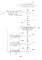
Fig. 1 is a flow chart of a method of controlling an air-cooled refrigerator according to an embodiment of the present disclosure; -
Fig. 2 is a flow chart of a method of controlling an air-cooled refrigerator according to another embodiment of the present disclosure; -
Fig. 3 is a block diagram of a system of controlling an air-cooled refrigerator according to an embodiment of the present disclosure; -
Fig. 4 is a schematic diagram of a system of controlling an air-cooled refrigerator according to an embodiment of the present disclosure; -
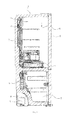
Fig. 5 is a schematic cross-sectional view of an air-cooled refrigerator according to an embodiment of the present disclosure; -
Fig. 6 is a schematic view of a refrigerating evaporator of an air-cooled refrigerator according to an embodiment of the present disclosure; and -
Fig. 7 is an enlarged schematic view of the part I shown inFig. 6 . - Embodiments of the present disclosure will be described in detail in the following descriptions, examples of which are shown in the accompanying drawings, in which the same or similar elements and elements having same or similar functions are denoted by like reference numerals throughout the descriptions. The embodiments described herein with reference to the accompanying drawings are explanatory and illustrative, which are used to generally understand the present disclosure. The embodiments shall not be construed to limit the present disclosure.
- It is to be understood that phraseology and terminology used herein with reference to device or element orientation (such as, terms like "longitudinal", "lateral", "front", "rear", "right", "left", "lower", "upper", "horizontal", "vertical", "above", "below", "up", "top", "bottom" as well as derivative thereof such as "horizontally", "downwardly", "upwardly", etc.) are only used to simplify description of the present invention, and do not alone indicate or imply that the device or element referred to must have or operated in a particular orientation.
- An air-cooled refrigerator according to an embodiment of the present disclosure will be described below with reference to
Fig. 5 . As shown inFig. 5 , the air-cooled refrigerator according to an embodiment of the present disclosure comprises abody 1 and adoor 2. Thebody 1 defines a refrigeratingcompartment 5 located in an upper portion thereof and afreezing compartment 7 located in a lower portion thereof. Alternatively, a temperature change compartment B may also be disposed between the refrigeratingcompartment 5 and thefreezing compartment 7. A refrigeratingevaporator 3 is disposed at a back surface (left side inFig. 5 ) of the refrigeratingcompartment 5, a refrigerating air passage F is disposed between the refrigeratingevaporator 3 and the refrigeratingcompartment 5, foam materials (not shown) may be disposed in the refrigerating air passage F, and a refrigeratingfan 4 is disposed between the refrigerating air passage F and the refrigeratingcompartment 5 for transferring a cold air generated in the refrigeratingevaporator 3 to the refrigeratingcompartment 5. In the embodiment shown inFig. 5 , the temperature change compartment B is also refrigerated by the cold air generated in the refrigeratingevaporator 3, however, the present disclosure is not limited to this. - A
freezing evaporator 6 is disposed at a back surface of thefreezing compartment 7. Acompressor 9 is provided at the bottom of thebody 1, and acondenser 8 is disposed at the right side of thecompressor 9 at the bottom of thebody 1. - The system of controlling the air-cooled refrigerator according to an embodiment of the present disclosure will be described hereinafter with reference to
Fig. 4 . As shown inFig. 4 , the refrigeratingevaporator 3 and thefreezing evaporator 6 are disposed in one refrigerating system, and thecompressor 9, thecondenser 8, ananti-condensation tube 12, a drying filter 11, anelectromagnetic valve 10 as a switching unit, and thefreezing evaporator 6 are connected, in which theelectromagnetic valve 10 is connected with thefreezing evaporator 6 via a freezingcapillary tube 13. In addition, theelectromagnetic valve 10 is also connected with the refrigeratingevaporator 3 via a refrigeratingcapillary tube 14, and the refrigeratingevaporator 3 and the refrigeratingcapillary tube 14 are connected with the freezingcapillary tube 13 in parallel. Theelectromagnetic valve 10 is used for supplying a refrigerant to the refrigeratingevaporator 3 selectively, thus controlling the refrigerating of the refrigeratingcompartment 5 selectively. - With the air-cooled refrigerator according to an embodiment of the present disclosure, the refrigerating
compartment 5 and thefreezing compartment 7 are refrigerated by individual evaporators respectively, and only one refrigerating system is used, thus decreasing the total number of the members and reducing the cost accordingly. - In some embodiments, as shown in
Figs. 6-7 , therefrigerating evaporator 3 comprises acoil pipe 31 and a plurality offins 32. Thecoil pipe 31 is extended into a corrugated shape in a longitudinal direction, the vertical direction inFig. 6 , to form a plurality of layers ofpipe segments 311 in the longitudinal direction. And adjacent layers of thepipe segments 311 are connected with each other via an arcuatetransition pipe segment 312 so that two adjacent layers ofpipe segments 311 and the arcuatetransition pipe segment 312 form into a substantially U shape. The plurality offins 32 are arranged in a lateral direction, i.e. the left-to-right direction inFig. 6 , and connected with the plurality of layers ofpipe segments 311 respectively, and at least a part of thefins 32 is discontinuous in the longitudinal direction. In some embodiments, the fact that at least a part of thefins 32 is discontinuous in the longitudinal direction may be achieved by disposing a break point in one integral fin. Alternatively, thefins 32 connected on each layer ofpipe segment 311 may be individual ones, so that thefins 32 connected with the plurality of layers ofpipe segments 311 respectively are discontinuous in the longitudinal direction. - In some specific examples, as shown in
Fig. 6 , eachfin 32 has a plurality of break points between two adjacent layers ofpipe segments 311 in the longitudinal direction, so that eachfin 32 is formed by a plurality of segments which are discontinuous in the longitudinal direction. - In a specific example, each
fin 32 is formed with a plurality of via holes (not shown) through which the plurality of the layers of thepipe segments 311 are penetrated respectively so as to connect the plurality offins 32 with the plurality of the layers of thepipe segments 311 respectively. Alternatively, the plurality offins 32 may be welded to the plurality of the layers of thepipe segments 311 respectively. - With the air-cooled refrigerator according to an embodiment of the present disclosure, because the
fins 32 have a structure which is discontinuous in the longitudinal direction, the surface tension of water may be used to form small water drops at a bottom end of eachfin 32, thus avoiding loss of moistures caused by flow and accumulation of water drops along conventional fins which are continuous in the longitudinal direction and prolonging the time period during which water drops remain on the refrigeratingevaporator 3. Moreover, the small water drops may be brought into therefrigerating compartment 5 by the way of water vapor circulation, so that a higher humidity in therefrigerating compartment 5 may be maintained. For example, small water drops generated during defrosting on the plurality offins 32 may be converted into water vapors and brought into therefrigerating compartment 5 by the refrigeratingfan 4, thus reducing loss of moistures in therefrigerating compartment 5 effectively and avoiding the fact that water drops flow downwards quickly along the conventional fins which are continuous in the longitudinal direction and then are accumulated in a water-containing plate in a bottom of the air-cooled refrigerator to be discharged out of thebody 1. Therefore, therefrigerating compartment 5 may be in a high-humidity state, moisture loss in food may be reduced, the refreshing time of the food may be prolonged, and the refreshing performance of therefrigerating compartment 5 may be improved significantly. - The method and system of controlling the air-cooled refrigerator according to an embodiment of the present disclosure will be described below with reference to
Figs. 1-3 . With the method and the system of controlling the air-cooled refrigerator according to an embodiment of the present disclosure, the rotating speed of the refrigeratingfan 4 may be appropriately and flexibly adjusted according to the temperature of the refrigeratingevaporator 3, so that defrosting water on the refrigeratingevaporator 3 may be sent into therefrigerating compartment 5 and the humidity in therefrigerating compartment 5 may be maintained. - As shown in
Fig. 1 , the method of controlling the air-cooled refrigerator for maintaining the humidity in therefrigerating compartment 5 according to an embodiment of the present disclosure comprises the following steps. - First, a temperature TL in the
refrigerating compartment 5 is detected (step S101). - Then, it is determined whether the temperature TL in the
refrigerating compartment 5 is greater than or equal to a first predetermined temperature T1 (step S102). If TL≥T1, the refrigeratingevaporator 3 is started to refrigerate therefrigerating compartment 5 and a rotating speed of the refrigeratingfan 4 is adjusted to r1 (step S103). - If the temperature TL<T1, it is determined whether the temperature TL is less than a second predetermined temperature T2 (step S104).
- If the temperature TL<T2, the refrigerating
evaporator 3 is stopped and a temperature TH of the refrigeratingevaporator 3 is detected (step S105). - Finally, the rotating speed of the refrigerating
fan 4 is adjusted according to the temperature TH of the refrigeratingevaporator 3 to adjust a humidity in the refrigerating compartment 5 (step S106). - With the method of controlling the air-cooled refrigerator according to an embodiment of the present disclosure, when the temperature in the
refrigerating compartment 5 is greater than or equal to the first predetermined temperature T1, the refrigeratingevaporator 3 is started to refrigerate therefrigerating compartment 5. When the temperature in therefrigerating compartment 5 meets normal needs, the refrigeratingevaporator 3 is stopped, but the refrigeratingfan 4 is not stopped at this time but continues operating to send defrosting water on the surface of the refrigeratingevaporator 3 into therefrigerating compartment 5 and adjust the rotating speed of the refrigeratingfan 4 according to the temperature of the refrigeratingevaporator 3. Therefore, a higher humidity in therefrigerating compartment 5 may be maintained, moisture loss in food in therefrigerating compartment 5 may be reduced, and the refreshing effect may be enhanced. Moreover, frosting on the refrigeratingevaporator 3 may be relatively reduced, thus prolonging the defrosting period of therefrigerating compartment 5, that is, decreasing the working times of a heating wire in therefrigerating compartment 5 per time unit. Therefore, electric energy consumption may be reduced, and the effect of saving energy may be achieved. - In some embodiments, the first predetermined temperature T1 is a maximum allowable temperature in the
refrigerating compartment 5, and the second predetermined temperature T2 is a minimum allowable temperature in therefrigerating compartment 5. For example, if the temperature in therefrigerating compartment 5 is usually between 1 Celsius degree and 6 Celsius degrees, then the first predetermined temperature T1 may be determined to be 6 Celsius degrees, and the second predetermined temperature T2 may be 1 Celsius degree. - In some embodiments, if T2≤TL<T1, for example, the temperature in the
refrigerating compartment 5 is decreased from T1 to T2, then the refrigeratingevaporator 3 continues operating, and the rotating speed of the refrigeratingfan 4 is maintained at r1, until TL is less than T2. The operation of the refrigeratingevaporator 3 is stopped when TL is less than T1. Alternatively, when T2≤TL<T1, the operation of the refrigeratingevaporator 3 may also be stopped. - In some embodiments, the step of adjusting the rotating speed of the refrigerating
fan 4 comprises decreasing the rotating speed of the refrigeratingfan 4 gradually with an increase of the temperature TH. In other words, the higher the temperature of the refrigeratingevaporator 3, the lower the rotating speed of the refrigeratingfan 4 is, and the higher the humidity in therefrigerating compartment 5. - The method of controlling the air-cooled refrigerator according to another embodiment of the present disclosure will be described below with reference to
Fig. 1 . In the embodiment shown inFig. 2 , the step of adjusting the rotating speed of the refrigeratingfan 4 comprises decreasing the rotating speed of the refrigeratingfan 4 stage by stage with an increase of the temperature TH. - More particularly, as shown in
Fig. 2 , the method of controlling the air-cooled refrigerator according to another embodiment of the present disclosure comprises the following steps. - First, a temperature TL in the
refrigerating compartment 5 is detected (step S201). - Then, it is determined whether the temperature TL in the
refrigerating compartment 5 is greater than or equal to a first predetermined temperature T1 (step S202). If TL≥T1, the refrigeratingevaporator 3 is started to refrigerate therefrigerating compartment 5 and a rotating speed of the refrigeratingfan 4 is adjusted to r1 (step S203). - If the temperature TL<T1, it is determined whether the temperature TL is less than a second predetermined temperature T2 (step S204).
- If the temperature TL<T2, the refrigerating
evaporator 3 is stopped and a temperature TH of the refrigeratingevaporator 3 is detected (step S205). - Next, the rotating speed of the refrigerating
fan 4 is adjusted according to the temperature TH of the refrigeratingevaporator 3 to adjust a humidity in therefrigerating compartment 5. More particularly, it is determined whether TH is less than t3 (step S2601), and the rotating speed of the refrigeratingfan 4 is adjusted to r2 if TH<t3 (step S2602). If TH is not less than t3, it is determined whether TH is less than t4 (step S2603), and the rotating speed of the refrigeratingfan 4 is adjusted to r3 if t3≤TH<t4 (step S2604). If TH is not less than t4, it is determined that TH≥t4 (step S2605), and the rotating speed of the refrigeratingfan 4 is adjusted to r4 (step S2606). t3 is a third predetermined temperature, t4 is a fourth predetermined temperature, and r4 < r3 < r2 < r1. - In the above embodiment, the rotating speed of the refrigerating
fan 4 is adjusted according to the temperature TH of the refrigeratingevaporator 3 stage by stage, in which the temperature TH of the refrigeratingevaporator 3 is divided into three stages. It would be appreciated that the present disclosure is not limited to this, and any suitable quantity of stages may be divided according to applications. - According to the above embodiment of the present disclosure, the rotating speed of the refrigerating
fan 4 may be adjusted according to the temperature TH of the refrigeratingevaporator 3 stage by stage and flexibly, thus ensuring the humidity in therefrigerating compartment 5 and improving the freshness in therefrigerating compartment 5. - The system of controlling the air-cooled refrigerator according to an embodiment of the present disclosure will be described below with reference to
Fig. 3 . As shown inFig. 3 , the system of controlling the air-cooled refrigerator according to an embodiment of the present disclosure comprises a refrigerating compartmenttemperature detecting unit 18, a refrigerating compartmenttemperature determining unit 19 connected with the refrigerating compartmenttemperature detecting unit 18, a refrigerating evaporatortemperature detecting unit 20, and acontrol unit 15. - The refrigerating compartment
temperature detecting unit 18 is, for example, a temperature sensor for detecting a temperature TL in therefrigerating compartment 5. The refrigerating compartmenttemperature determining unit 19 is used for determining whether T2≤TL< T1. The refrigerating evaporatortemperature detecting unit 20 is used for detecting a temperature TH of the refrigeratingevaporator 3. - The
control unit 15 is used for starting the refrigeratingevaporator 3 to refrigerate therefrigerating compartment 5 and adjusting a rotating speed of the refrigeratingfan 4 to r1 if TL≥T1, and stopping an operation of the refrigeratingevaporator 3 and adjusting the rotating speed of the refrigeratingfan 4 according to the temperature TH to adjust a humidity in therefrigerating compartment 5 if TL<T2. - In some embodiments, as shown in
Fig. 3 , particularly, thecontrol unit 15 may comprise a refrigeratingcontrol unit 17 and a refrigeratingfan control unit 16. The refrigeratingcontrol unit 17 is used for controlling the operation and the stopping of the refrigeratingevaporator 3, and the refrigeratingfan control unit 16 is used for controlling the refrigeratingfan 4. - Alternatively, if T2≤TL<T1, the refrigerating
evaporator 3 is controlled by thecontrol unit 15 to continue operating, and the rotating speed of the refrigeratingfan 4 is maintained at r1. - The rotating speed of the refrigerating
fan 4 may be decreased by thecontrol unit 15 gradually or stage by stage with an increase of the temperature TH. - In one example, the
control unit 15 may further comprise a refrigerating evaporatortemperature determining unit 21 for determining the temperature TH of the refrigeratingevaporator 3. For example, the rotating speed of the refrigeratingfan 4 is adjusted to r2 by thecontrol unit 15 if it is determined by the refrigerating evaporatortemperature determining unit 21 that TH<t3, the rotating speed of the refrigeratingfan 4 is adjusted to r3 by thecontrol unit 15 if it is determined by the refrigerating evaporator temperature, determiningunit 21 that t3≤TH<t4, and the rotating speed of the refrigeratingfan 4 is adjusted to r4 by thecontrol unit 15 if it is determined by the refrigerating evaporatortemperature determining unit 21 that TH≥t4, where t3 is a third predetermined temperature, t4 is a fourth predetermined temperature, and r4 < r3 < r2 < r1. - With the system of controlling the air-cooled refrigerator according to an embodiment of the present disclosure, the rotating speed of the refrigerating
fan 4 may be adjusted according to the temperature of the refrigeratingevaporator 3, so that defrosting water on the refrigeratingevaporator 3 may be sent into the refrigerating compartment, 5. Therefore, a higher humidity in therefrigerating compartment 5 may be maintained, moisture loss in food in therefrigerating compartment 5 may be reduced, and the refreshing effect may be enhanced. Moreover, frosting on the refrigeratingevaporator 3 may be relatively reduced, thus prolonging the defrosting period of therefrigerating compartment 5, that is, decreasing the working times of a heating wire in therefrigerating compartment 5 per time unit. Therefore, electric energy consumption may be reduced, and the effect of saving energy may be achieved. - It should be noted that in the above description, the
control unit 15, the refrigerating compartmenttemperature determining unit 19 and the refrigerating evaporatortemperature determining unit 21 may be separately provided. However, it would be appreciated by those skilled in the art that thecontrol unit 15, the refrigerating compartmenttemperature determining unit 19 and the refrigerating evaporatortemperature determining unit 21 may be integrated in a single chip. - The air-cooled refrigerator according to an embodiment of the present disclosure may comprise the above-mentioned system. The operation of the air-cooled refrigerator according to an embodiment of the present disclosure will be simply described below.
- When the temperature in each of the
refrigerating compartment 5 and the freezing compartment, 7 are higher than a predetermined temperature and therefrigerating compartment 5 and the freezingcompartment 7 need to be refrigerated, thecompressor 9 is started by thecontrol unit 15, and the refrigerant is switched into the refrigeratingcapillary tube 14 by the switching unit (electromagnetic valve) 10, flows into the refrigeratingevaporator 3 from the refrigeratingcapillary tube 14, and then flows into the freezingevaporator 6 from the refrigeratingevaporator 3, thus refrigerating therefrigerating compartment 5 and the freezingcompartment 7. At this time, the rotating speed of the refrigeratingfan 4 is controlled to be r1 by thecontrol unit 15. When therefrigerating compartment 5 does not need to be refrigerated but the freezingcompartment 7 needs to be refrigerated, the refrigerant is switched into the freezingcapillary tube 13 by theelectromagnetic valve 10 under the control of thecontrol unit 15, and flows into the freezingevaporator 6 to refrigerate the freezingcompartment 7. Because no refrigerants flow into the refrigeratingevaporator 3, therefrigerating compartment 5 is not refrigerated. When neither therefrigerating compartment 5 nor the freezingcompartment 7 needs to be refrigerated, the operation of thecompressor 9 is stopped by thecontrol unit 15. - When the
refrigerating compartment 5 is not refrigerated, the temperature TH of the refrigeratingevaporator 3 is detected by the refrigerating evaporatortemperature detecting unit 20, the rotating speed of the refrigeratingfan 4 is adjusted to r2 by thecontrol unit 15 if TH<t3, the rotating speed of the refrigeratingfan 4 is adjusted to r3 by thecontrol unit 15 if t3≤TH<t4, and the rotating speed of the refrigeratingfan 4 is adjusted to r4 by thecontrol unit 15 if TH≥t4. Therefore, defrosting water on the refrigeratingevaporator 3 may be sent into therefrigerating compartment 5 by the refrigeratingfan 4, thus maintaining the humidity and the freshness in therefrigerating compartment 5. - According to an embodiment of the present disclosure, separate evaporators and separate air passages are disposed in the refrigerating compartment and the freezing compartment of the air-cooled refrigerator respectively, and the working state of the refrigerating fan is adjusted in an appropriate and flexible manner, so that the refrigerating compartment may be in a high-humidity state, moisture loss in food may be reduced, and the refreshing time of the food may be prolonged. Therefore, the refreshing performance of the refrigerating compartment may be improved significantly. Meanwhile, because the refrigerating compartment and the freezing compartment have separate air passage circulation systems, tainting by odors among foods may be avoided, thus further meeting the requirement of the user.
- Moreover, because defrosting water on the refrigerating
evaporator 3 may be sent into therefrigerating compartment 5 by the refrigeratingfan 4, a higher humidity in therefrigerating compartment 5 may be maintained, moisture loss in food in therefrigerating compartment 5 may be reduced, and the refreshing effect may be enhanced. Moreover, frosting on the refrigeratingevaporator 3 may be relatively reduced, thus prolonging the defrosting period of therefrigerating compartment 5, that is, decreasing the working times of a heating wire in therefrigerating compartment 5 per time unit. Therefore, electric energy consumption may be reduced, and the effect of saving energy may be achieved accordingly. - Reference throughout this specification to "an embodiment", "some embodiments", "one embodiment", "an example", "a specific examples", or "some examples" means that a particular feature, structure, material, or characteristic described in connection with the embodiment or example is included in at least one embodiment or example of the disclosure. Thus, the appearances of the phrases such as "in some embodiments", "in one embodiment", "in an embodiment", "an example", "a specific examples", or "some examples" in various places throughout this specification are not necessarily referring to the same embodiment or example of the disclosure. Furthermore, the particular features, structures, materials, or characteristics may be combined in any suitable manner in one or more embodiments or examples,
- Although explanatory embodiments have been shown and described, it would be appreciated by those skilled in the art that changes, alternatives, and modifications may be made in the embodiments without deporting from spirit and principles of the disclosure. Such changes, alternatives, and modifications all fall into the scope of the claims and their equivalents.
Claims (15)
- A method of controlling an air-cooled refrigerator, the air-cooled refrigerator comprising a refrigerating compartment, a refrigerating evaporator, and a refrigerating fan for circulating an air between the refrigerating evaporator and the refrigerating compartment, the method comprising steps of:detecting a temperature TL in the refrigerating compartment;determining whether the temperature TL is greater than or equal to a first predetermined temperature, T1, and starting the refrigerating evaporator to refrigerate the refrigerating compartment and adjusting a rotating speed of the refrigerating fan to r1 if the temperature TL≥T1;determining whether the temperature TL is less than a second predetermined temperature T2 if the temperature TL<T1;stopping the refrigerating evaporator and detecting a temperature TH of the refrigerating evaporator if the temperature TL<T2; andadjusting the rotating speed of the refrigerating fan according to the temperature TH to adjust a humidity in the refrigerating compartment,
- The method according to claim 1, wherein the first predetermined temperature T1 is a maximum allowable temperature in the refrigerating compartment, and the second predetermined temperature T2 is a minimum allowable temperature in the refrigerating compartment.
- The method according to claim 1, wherein if T2≤TL<T1, the refrigerating evaporator continues operating, and the rotating speed of the refrigerating fan is maintained at r1.
- The method according to claim 1, wherein the step of adjusting the rotating speed of the refrigerating fan comprises decreasing the rotating speed of the refrigerating fan stage by stage with an increase of the temperature TH.
- The method according to claim 4, wherein the step of adjusting the rotating speed of the refrigerating fan further comprises:adjusting the rotating speed of the refrigerating fan to r2 if TH<t3;adjusting the rotating speed of the refrigerating fan to r3 if t3≤TH<t4; andadjusting the rotating speed of the refrigerating fan to r4 if TH≥t4, where t3 is a third predetermined temperature, t4 is a fourth predetermined temperature, and r4 < r3 < r2 < r1.
- The method according to claim 1, wherein the step of adjusting the rotating speed of the refrigerating fan comprises decreasing the rotating speed of the refrigerating fan gradually with an increase of the temperature TH.
- A system of controlling an air-cooled refrigerator, the air-cooled refrigerator comprising a refrigerating compartment, a refrigerating evaporator, and a refrigerating fan for circulating an air between the refrigerating evaporator and the refrigerating compartment, the system comprising:a refrigerating compartment temperature detecting unit for detecting a temperature TL in the refrigerating compartment;a refrigerating compartment temperature determining unit for determining whether T2≤TL< T1, where T1 is a first predetermined temperature, and T2 is a second predetermined temperature;a refrigerating evaporator temperature detecting unit for detecting a temperature, TH of the refrigerating evaporator; anda control unit for starting the refrigerating evaporator to refrigerate the refrigerating compartment and adjusting a rotating speed of the refrigerating fan to r1 if TL≥T1, and stopping an operation of the refrigerating evaporator and adjusting the rotating speed of the refrigerating fan according to the temperature TH to adjust a humidity in the refrigerating compartment if TL<T2.
- The system according to claim 7, wherein if T2≤TL<T1, the refrigerating evaporator is controlled by the control unit to continue operating, and the rotating speed of the refrigerating fan is maintained at r1.
- The system according to claim 7, wherein the rotating speed of the refrigerating fan is decreased by the control unit stage by stage with an increase of the temperature TH.
- The system according to claim 9, further comprising a refrigerating evaporator temperature determining unit for determining the temperature of the refrigerating evaporator, wherein the rotating speed of the refrigerating fan is adjusted to r2 by the control unit if it is determined by the refrigerating evaporator temperature determining unit that TH<t3,
the rotating speed of the refrigerating fan is adjusted to r3 by the control unit if it is determined by the refrigerating evaporator temperature determining unit that t3≤TH<t4, and
the rotating speed of the refrigerating fan is adjusted to r4 by the control unit if it is determined by the refrigerating evaporator temperature determining unit that TH≥t4, where t3 is a third predetermined temperature, t4 is a fourth predetermined temperature, and r4 < r3 < r2 < r1. - An air-cooled refrigerator comprising:a refrigerating compartment;a refrigerating evaporator; anda refrigerating fan for circulating an air between the refrigerating evaporator and the refrigerating compartment, wherein the air-cooled refrigerator further comprises a system according to any one of claims 7-10.
- The air-cooled refrigerator according to claim 11, further comprising a freezing compartment, a freezing evaporator, and a switching unit, wherein the switching unit is connected with the freezing evaporator via a freezing capillary tube, the refrigerating evaporator is connected with the switching unit via a refrigerating capillary tube, the refrigerating evaporator and the refrigerating capillary tube are connected with the freezing capillary tube in parallel, and the switching unit is controlled by the control unit to selectively supply a refrigerant to the refrigerating evaporator, to start or stop the refrigerating of the refrigerating compartment.
- The air-cooled refrigerator according to claim 11, wherein the refrigerating evaporator comprises a coil pipe and a plurality of fins, the coil pipe is extended into a corrugated shape in a longitudinal direction to form a plurality of layers of pipe segments in the longitudinal direction, the plurality of fins are arranged in a lateral direction and connected with the coil pipe respectively, and wherein at least a part of the fins have at least a break point in the longitudinal direction to be discontinuous in the longitudinal direction.
- The air-cooled refrigerator according to claim 13, wherein each fin has a plurality of break points between two adjacent layers of pipe segments.
- The air-cooled refrigerator according to claim 14, wherein each fin is formed with a plurality of via holes through which the plurality of the layers of the pipe segments are penetrated respectively.
Applications Claiming Priority (3)
| Application Number | Priority Date | Filing Date | Title |
|---|---|---|---|
| CN 201010138403 CN101937247B (en) | 2010-03-30 | 2010-03-30 | Air cooling refrigerator as well as moisture-preservation control method and system thereof |
| CN2010201593478U CN201662283U (en) | 2010-04-08 | 2010-04-08 | Finned evaporator and refrigerator |
| PCT/CN2010/077844 WO2011120293A1 (en) | 2010-03-30 | 2010-10-18 | Air cooled refrigerator, control method and control system thereof |
Publications (3)
| Publication Number | Publication Date |
|---|---|
| EP2505946A1 true EP2505946A1 (en) | 2012-10-03 |
| EP2505946A4 EP2505946A4 (en) | 2013-12-11 |
| EP2505946B1 EP2505946B1 (en) | 2017-09-13 |
Family
ID=44711332
Family Applications (1)
| Application Number | Title | Priority Date | Filing Date |
|---|---|---|---|
| EP10848752.1A Active EP2505946B1 (en) | 2010-03-30 | 2010-10-18 | A system of controlling an air-cooled refrigerator |
Country Status (4)
| Country | Link |
|---|---|
| US (1) | US8677771B2 (en) |
| EP (1) | EP2505946B1 (en) |
| AU (1) | AU2010350112B2 (en) |
| WO (1) | WO2011120293A1 (en) |
Cited By (3)
| Publication number | Priority date | Publication date | Assignee | Title |
|---|---|---|---|---|
| EP3351879A1 (en) * | 2017-01-24 | 2018-07-25 | Heatcraft Refrigeration Products LLC | Method and apparatus for enhanced off-cycle defrost |
| CN108885054A (en) * | 2016-03-24 | 2018-11-23 | Lg 电子株式会社 | Refrigerator and its control method |
| CN109060035A (en) * | 2018-08-28 | 2018-12-21 | 重庆大学 | Internet of Things intelligence sensor |
Families Citing this family (11)
| Publication number | Priority date | Publication date | Assignee | Title |
|---|---|---|---|---|
| JP5766000B2 (en) * | 2011-04-25 | 2015-08-19 | ホシザキ電機株式会社 | Cooling storage |
| ITTO20131094A1 (en) * | 2013-12-31 | 2015-07-01 | Indesit Co Spa | METHOD AND DEVICE FOR CHECKING A DEEP FREEZING PHASE IN A REFRIGERATOR OF THE COMBINED SINGLE-ADJUSTMENT TYPE, AND ITS REFRIGERATOR APPARATUS |
| ITTO20131095A1 (en) * | 2013-12-31 | 2015-07-01 | Indesit Co Spa | METHOD AND DEVICE FOR CHECKING A DEEP FREEZING PHASE IN A REFRIGERATOR OF THE COMBINED SINGLE-ADJUSTMENT TYPE, AND ITS REFRIGERATOR APPARATUS |
| ITTO20131093A1 (en) * | 2013-12-31 | 2015-07-01 | Indesit Co Spa | METHOD AND DEVICE FOR CHECKING A DEEP FREEZING PHASE IN A REFRIGERATOR OF THE COMBINED SINGLE-ADJUSTMENT TYPE, AND ITS REFRIGERATOR APPARATUS |
| WO2017105047A1 (en) * | 2015-12-15 | 2017-06-22 | 엘지전자 주식회사 | Refrigerator and control method therefor |
| US11559147B2 (en) | 2019-05-07 | 2023-01-24 | Carrier Corporation | Refrigerated display cabinet utilizing a radial cross flow fan |
| US11116333B2 (en) | 2019-05-07 | 2021-09-14 | Carrier Corporation | Refrigerated display cabinet including microchannel heat exchangers |
| CN113465283A (en) * | 2020-03-31 | 2021-10-01 | 博西华电器(江苏)有限公司 | Control method for refrigerator and refrigerator |
| CN116147272A (en) * | 2021-11-19 | 2023-05-23 | 青岛海尔电冰箱有限公司 | Refrigerator control method and refrigerator |
| CN115978877B (en) * | 2023-01-11 | 2024-08-13 | 长虹美菱股份有限公司 | Refrigerator with humidification function and control method |
| CN119178280B (en) * | 2024-10-24 | 2025-12-05 | 长虹美菱股份有限公司 | Refrigerator control methods and refrigerators |
Family Cites Families (17)
| Publication number | Priority date | Publication date | Assignee | Title |
|---|---|---|---|---|
| GB1553666A (en) * | 1976-09-20 | 1979-09-26 | Smiths Industries Ltd | Sequence-control apparatus |
| US5255530A (en) * | 1992-11-09 | 1993-10-26 | Whirlpool Corporation | System of two zone refrigerator temperature control |
| KR0182533B1 (en) * | 1994-11-15 | 1999-05-01 | 윤종용 | Refrigerator and its temperature control method |
| KR19980054641A (en) * | 1996-12-27 | 1998-09-25 | 배순훈 | How to control fan motor of refrigerator |
| TW528847B (en) * | 1998-06-18 | 2003-04-21 | Hitachi Ltd | Refrigerator |
| JP3874941B2 (en) * | 1998-09-16 | 2007-01-31 | 株式会社東芝 | refrigerator |
| US7237395B2 (en) * | 2003-12-22 | 2007-07-03 | General Electric Company | Methods and apparatus for controlling refrigerators |
| EP1809962A1 (en) * | 2004-11-02 | 2007-07-25 | LG Electronics, Inc. | Defrost operating method for refrigerator |
| JP2006177632A (en) * | 2004-12-24 | 2006-07-06 | Denso Corp | Refrigeration cycle |
| KR101095554B1 (en) * | 2004-12-30 | 2011-12-19 | 삼성전자주식회사 | Operation control method of refrigerator |
| JP2005331239A (en) * | 2005-08-04 | 2005-12-02 | Toshiba Corp | refrigerator |
| KR100687931B1 (en) * | 2005-08-11 | 2007-02-27 | 삼성전자주식회사 | How to control the operation of the refrigerator |
| KR20070054462A (en) * | 2005-11-23 | 2007-05-29 | 삼성전자주식회사 | Refrigerator and its control method |
| US20080178621A1 (en) * | 2007-01-26 | 2008-07-31 | Samsung Electronics Co., Ltd. | Refrigerator and operation control method thereof |
| KR20090074292A (en) * | 2008-01-02 | 2009-07-07 | 삼성전자주식회사 | Refrigerator and its control method |
| CN201203318Y (en) * | 2008-04-24 | 2009-03-04 | 海信(北京)电器有限公司 | Wind cooling refrigerator |
| CN101586898A (en) * | 2008-05-20 | 2009-11-25 | 海信(北京)电器有限公司 | Air-cooled refrigerator and defrosting method of same |
-
2010
- 2010-10-18 AU AU2010350112A patent/AU2010350112B2/en active Active
- 2010-10-18 WO PCT/CN2010/077844 patent/WO2011120293A1/en not_active Ceased
- 2010-10-18 EP EP10848752.1A patent/EP2505946B1/en active Active
-
2012
- 2012-05-16 US US13/472,697 patent/US8677771B2/en active Active
Cited By (7)
| Publication number | Priority date | Publication date | Assignee | Title |
|---|---|---|---|---|
| CN108885054A (en) * | 2016-03-24 | 2018-11-23 | Lg 电子株式会社 | Refrigerator and its control method |
| EP3435014A4 (en) * | 2016-03-24 | 2020-01-01 | LG Electronics Inc. | REFRIGERATOR AND ITS CONTROL METHOD |
| CN108885054B (en) * | 2016-03-24 | 2020-11-13 | Lg 电子株式会社 | Refrigerator and control method thereof |
| US11067324B2 (en) | 2016-03-24 | 2021-07-20 | Lg Electronics Inc. | Refrigerator and control method therefor |
| EP3351879A1 (en) * | 2017-01-24 | 2018-07-25 | Heatcraft Refrigeration Products LLC | Method and apparatus for enhanced off-cycle defrost |
| US10429122B2 (en) | 2017-01-24 | 2019-10-01 | Kysor Warren Epta Us Corporation | Method and apparatus for enhanced off-cycle defrost |
| CN109060035A (en) * | 2018-08-28 | 2018-12-21 | 重庆大学 | Internet of Things intelligence sensor |
Also Published As
| Publication number | Publication date |
|---|---|
| AU2010350112B2 (en) | 2014-09-25 |
| US20120222436A1 (en) | 2012-09-06 |
| EP2505946A4 (en) | 2013-12-11 |
| WO2011120293A1 (en) | 2011-10-06 |
| EP2505946B1 (en) | 2017-09-13 |
| US8677771B2 (en) | 2014-03-25 |
| AU2010350112A1 (en) | 2012-05-03 |
Similar Documents
| Publication | Publication Date | Title |
|---|---|---|
| US8677771B2 (en) | Air cooled refrigerator, method and system of controlling the same | |
| AU2011375631B2 (en) | Refrigerator | |
| CN106091566B (en) | A control method for an air-cooled refrigerator | |
| KR101319106B1 (en) | Refrigerator and freezer | |
| US12313305B2 (en) | Refrigerator | |
| US12222140B2 (en) | Method for controlling refrigerator | |
| JP7090198B2 (en) | refrigerator | |
| EP2580550B1 (en) | A cooling device | |
| CN108800747A (en) | Refrigerator and its control method | |
| CN108800704A (en) | Refrigerator and its control method | |
| US12038220B2 (en) | Refrigerator and deep freezing compartment defrost operation | |
| CN207247632U (en) | Evaporator assemblies and the refrigerator with the evaporator assemblies | |
| CN111609633A (en) | Air-cooled refrigerator | |
| CN116951874B (en) | Refrigerator and defrost control method thereof | |
| WO2015029409A1 (en) | Refrigerator | |
| US12163702B2 (en) | Method for controlling refrigerator | |
| US12130055B2 (en) | Refrigerator control method | |
| JP5031045B2 (en) | Freezer refrigerator | |
| JP2019027649A (en) | refrigerator | |
| JP2009250599A (en) | Refrigerator | |
| JP2008002731A (en) | refrigerator | |
| CN119983657A (en) | refrigerator | |
| JP2014156965A (en) | Freezer refrigerator | |
| KR20060041500A (en) | The structure of the wine cellar | |
| JP2007278660A (en) | refrigerator |
Legal Events
| Date | Code | Title | Description |
|---|---|---|---|
| PUAI | Public reference made under article 153(3) epc to a published international application that has entered the european phase |
Free format text: ORIGINAL CODE: 0009012 |
|
| 17P | Request for examination filed |
Effective date: 20120419 |
|
| AK | Designated contracting states |
Kind code of ref document: A1 Designated state(s): AL AT BE BG CH CY CZ DE DK EE ES FI FR GB GR HR HU IE IS IT LI LT LU LV MC MK MT NL NO PL PT RO RS SE SI SK SM TR |
|
| DAX | Request for extension of the european patent (deleted) | ||
| A4 | Supplementary search report drawn up and despatched |
Effective date: 20131107 |
|
| RIC1 | Information provided on ipc code assigned before grant |
Ipc: F25D 17/06 20060101ALI20131101BHEP Ipc: F25D 11/02 20060101ALI20131101BHEP Ipc: F25D 29/00 20060101AFI20131101BHEP |
|
| 17Q | First examination report despatched |
Effective date: 20131121 |
|
| GRAP | Despatch of communication of intention to grant a patent |
Free format text: ORIGINAL CODE: EPIDOSNIGR1 |
|
| INTG | Intention to grant announced |
Effective date: 20160705 |
|
| GRAJ | Information related to disapproval of communication of intention to grant by the applicant or resumption of examination proceedings by the epo deleted |
Free format text: ORIGINAL CODE: EPIDOSDIGR1 |
|
| GRAJ | Information related to disapproval of communication of intention to grant by the applicant or resumption of examination proceedings by the epo deleted |
Free format text: ORIGINAL CODE: EPIDOSDIGR1 |
|
| GRAP | Despatch of communication of intention to grant a patent |
Free format text: ORIGINAL CODE: EPIDOSNIGR1 |
|
| INTG | Intention to grant announced |
Effective date: 20170202 |
|
| GRAS | Grant fee paid |
Free format text: ORIGINAL CODE: EPIDOSNIGR3 |
|
| GRAJ | Information related to disapproval of communication of intention to grant by the applicant or resumption of examination proceedings by the epo deleted |
Free format text: ORIGINAL CODE: EPIDOSDIGR1 |
|
| GRAL | Information related to payment of fee for publishing/printing deleted |
Free format text: ORIGINAL CODE: EPIDOSDIGR3 |
|
| INTC | Intention to grant announced (deleted) | ||
| GRAR | Information related to intention to grant a patent recorded |
Free format text: ORIGINAL CODE: EPIDOSNIGR71 |
|
| GRAA | (expected) grant |
Free format text: ORIGINAL CODE: 0009210 |
|
| RAP1 | Party data changed (applicant data changed or rights of an application transferred) |
Owner name: HEFEI MIDEA REFRIGERATOR CO., LTD. Owner name: HEFEI HUALING CO., LTD. |
|
| AK | Designated contracting states |
Kind code of ref document: B1 Designated state(s): AL AT BE BG CH CY CZ DE DK EE ES FI FR GB GR HR HU IE IS IT LI LT LU LV MC MK MT NL NO PL PT RO RS SE SI SK SM TR |
|
| INTG | Intention to grant announced |
Effective date: 20170808 |
|
| REG | Reference to a national code |
Ref country code: GB Ref legal event code: FG4D |
|
| REG | Reference to a national code |
Ref country code: CH Ref legal event code: EP |
|
| REG | Reference to a national code |
Ref country code: IE Ref legal event code: FG4D |
|
| REG | Reference to a national code |
Ref country code: AT Ref legal event code: REF Ref document number: 928569 Country of ref document: AT Kind code of ref document: T Effective date: 20171015 |
|
| REG | Reference to a national code |
Ref country code: DE Ref legal event code: R096 Ref document number: 602010045288 Country of ref document: DE |
|
| REG | Reference to a national code |
Ref country code: FR Ref legal event code: PLFP Year of fee payment: 8 |
|
| REG | Reference to a national code |
Ref country code: NL Ref legal event code: MP Effective date: 20170913 |
|
| REG | Reference to a national code |
Ref country code: LT Ref legal event code: MG4D |
|
| PG25 | Lapsed in a contracting state [announced via postgrant information from national office to epo] |
Ref country code: FI Free format text: LAPSE BECAUSE OF FAILURE TO SUBMIT A TRANSLATION OF THE DESCRIPTION OR TO PAY THE FEE WITHIN THE PRESCRIBED TIME-LIMIT Effective date: 20170913 Ref country code: SE Free format text: LAPSE BECAUSE OF FAILURE TO SUBMIT A TRANSLATION OF THE DESCRIPTION OR TO PAY THE FEE WITHIN THE PRESCRIBED TIME-LIMIT Effective date: 20170913 Ref country code: LT Free format text: LAPSE BECAUSE OF FAILURE TO SUBMIT A TRANSLATION OF THE DESCRIPTION OR TO PAY THE FEE WITHIN THE PRESCRIBED TIME-LIMIT Effective date: 20170913 Ref country code: HR Free format text: LAPSE BECAUSE OF FAILURE TO SUBMIT A TRANSLATION OF THE DESCRIPTION OR TO PAY THE FEE WITHIN THE PRESCRIBED TIME-LIMIT Effective date: 20170913 Ref country code: NO Free format text: LAPSE BECAUSE OF FAILURE TO SUBMIT A TRANSLATION OF THE DESCRIPTION OR TO PAY THE FEE WITHIN THE PRESCRIBED TIME-LIMIT Effective date: 20171213 |
|
| REG | Reference to a national code |
Ref country code: AT Ref legal event code: MK05 Ref document number: 928569 Country of ref document: AT Kind code of ref document: T Effective date: 20170913 |
|
| PG25 | Lapsed in a contracting state [announced via postgrant information from national office to epo] |
Ref country code: ES Free format text: LAPSE BECAUSE OF FAILURE TO SUBMIT A TRANSLATION OF THE DESCRIPTION OR TO PAY THE FEE WITHIN THE PRESCRIBED TIME-LIMIT Effective date: 20170913 Ref country code: BG Free format text: LAPSE BECAUSE OF FAILURE TO SUBMIT A TRANSLATION OF THE DESCRIPTION OR TO PAY THE FEE WITHIN THE PRESCRIBED TIME-LIMIT Effective date: 20171213 Ref country code: LV Free format text: LAPSE BECAUSE OF FAILURE TO SUBMIT A TRANSLATION OF THE DESCRIPTION OR TO PAY THE FEE WITHIN THE PRESCRIBED TIME-LIMIT Effective date: 20170913 Ref country code: RS Free format text: LAPSE BECAUSE OF FAILURE TO SUBMIT A TRANSLATION OF THE DESCRIPTION OR TO PAY THE FEE WITHIN THE PRESCRIBED TIME-LIMIT Effective date: 20170913 |
|
| PG25 | Lapsed in a contracting state [announced via postgrant information from national office to epo] |
Ref country code: NL Free format text: LAPSE BECAUSE OF FAILURE TO SUBMIT A TRANSLATION OF THE DESCRIPTION OR TO PAY THE FEE WITHIN THE PRESCRIBED TIME-LIMIT Effective date: 20170913 |
|
| PG25 | Lapsed in a contracting state [announced via postgrant information from national office to epo] |
Ref country code: RO Free format text: LAPSE BECAUSE OF FAILURE TO SUBMIT A TRANSLATION OF THE DESCRIPTION OR TO PAY THE FEE WITHIN THE PRESCRIBED TIME-LIMIT Effective date: 20170913 Ref country code: PL Free format text: LAPSE BECAUSE OF FAILURE TO SUBMIT A TRANSLATION OF THE DESCRIPTION OR TO PAY THE FEE WITHIN THE PRESCRIBED TIME-LIMIT Effective date: 20170913 Ref country code: CZ Free format text: LAPSE BECAUSE OF FAILURE TO SUBMIT A TRANSLATION OF THE DESCRIPTION OR TO PAY THE FEE WITHIN THE PRESCRIBED TIME-LIMIT Effective date: 20170913 |
|
| PG25 | Lapsed in a contracting state [announced via postgrant information from national office to epo] |
Ref country code: SM Free format text: LAPSE BECAUSE OF FAILURE TO SUBMIT A TRANSLATION OF THE DESCRIPTION OR TO PAY THE FEE WITHIN THE PRESCRIBED TIME-LIMIT Effective date: 20170913 Ref country code: AT Free format text: LAPSE BECAUSE OF FAILURE TO SUBMIT A TRANSLATION OF THE DESCRIPTION OR TO PAY THE FEE WITHIN THE PRESCRIBED TIME-LIMIT Effective date: 20170913 Ref country code: IS Free format text: LAPSE BECAUSE OF FAILURE TO SUBMIT A TRANSLATION OF THE DESCRIPTION OR TO PAY THE FEE WITHIN THE PRESCRIBED TIME-LIMIT Effective date: 20180113 Ref country code: SK Free format text: LAPSE BECAUSE OF FAILURE TO SUBMIT A TRANSLATION OF THE DESCRIPTION OR TO PAY THE FEE WITHIN THE PRESCRIBED TIME-LIMIT Effective date: 20170913 Ref country code: EE Free format text: LAPSE BECAUSE OF FAILURE TO SUBMIT A TRANSLATION OF THE DESCRIPTION OR TO PAY THE FEE WITHIN THE PRESCRIBED TIME-LIMIT Effective date: 20170913 |
|
| REG | Reference to a national code |
Ref country code: CH Ref legal event code: PL |
|
| REG | Reference to a national code |
Ref country code: DE Ref legal event code: R097 Ref document number: 602010045288 Country of ref document: DE |
|
| PG25 | Lapsed in a contracting state [announced via postgrant information from national office to epo] |
Ref country code: MC Free format text: LAPSE BECAUSE OF FAILURE TO SUBMIT A TRANSLATION OF THE DESCRIPTION OR TO PAY THE FEE WITHIN THE PRESCRIBED TIME-LIMIT Effective date: 20170913 |
|
| PLBE | No opposition filed within time limit |
Free format text: ORIGINAL CODE: 0009261 |
|
| STAA | Information on the status of an ep patent application or granted ep patent |
Free format text: STATUS: NO OPPOSITION FILED WITHIN TIME LIMIT |
|
| REG | Reference to a national code |
Ref country code: IE Ref legal event code: MM4A |
|
| PG25 | Lapsed in a contracting state [announced via postgrant information from national office to epo] |
Ref country code: DK Free format text: LAPSE BECAUSE OF FAILURE TO SUBMIT A TRANSLATION OF THE DESCRIPTION OR TO PAY THE FEE WITHIN THE PRESCRIBED TIME-LIMIT Effective date: 20170913 Ref country code: CH Free format text: LAPSE BECAUSE OF NON-PAYMENT OF DUE FEES Effective date: 20171031 Ref country code: LU Free format text: LAPSE BECAUSE OF NON-PAYMENT OF DUE FEES Effective date: 20171018 Ref country code: LI Free format text: LAPSE BECAUSE OF NON-PAYMENT OF DUE FEES Effective date: 20171031 |
|
| 26N | No opposition filed |
Effective date: 20180614 |
|
| REG | Reference to a national code |
Ref country code: BE Ref legal event code: MM Effective date: 20171031 |
|
| PG25 | Lapsed in a contracting state [announced via postgrant information from national office to epo] |
Ref country code: BE Free format text: LAPSE BECAUSE OF NON-PAYMENT OF DUE FEES Effective date: 20171031 |
|
| PG25 | Lapsed in a contracting state [announced via postgrant information from national office to epo] |
Ref country code: MT Free format text: LAPSE BECAUSE OF NON-PAYMENT OF DUE FEES Effective date: 20171018 |
|
| REG | Reference to a national code |
Ref country code: FR Ref legal event code: PLFP Year of fee payment: 9 |
|
| PG25 | Lapsed in a contracting state [announced via postgrant information from national office to epo] |
Ref country code: IE Free format text: LAPSE BECAUSE OF NON-PAYMENT OF DUE FEES Effective date: 20171018 |
|
| PG25 | Lapsed in a contracting state [announced via postgrant information from national office to epo] |
Ref country code: SI Free format text: LAPSE BECAUSE OF FAILURE TO SUBMIT A TRANSLATION OF THE DESCRIPTION OR TO PAY THE FEE WITHIN THE PRESCRIBED TIME-LIMIT Effective date: 20170913 |
|
| PG25 | Lapsed in a contracting state [announced via postgrant information from national office to epo] |
Ref country code: HU Free format text: LAPSE BECAUSE OF FAILURE TO SUBMIT A TRANSLATION OF THE DESCRIPTION OR TO PAY THE FEE WITHIN THE PRESCRIBED TIME-LIMIT; INVALID AB INITIO Effective date: 20101018 |
|
| PG25 | Lapsed in a contracting state [announced via postgrant information from national office to epo] |
Ref country code: CY Free format text: LAPSE BECAUSE OF NON-PAYMENT OF DUE FEES Effective date: 20170913 |
|
| PG25 | Lapsed in a contracting state [announced via postgrant information from national office to epo] |
Ref country code: MK Free format text: LAPSE BECAUSE OF FAILURE TO SUBMIT A TRANSLATION OF THE DESCRIPTION OR TO PAY THE FEE WITHIN THE PRESCRIBED TIME-LIMIT Effective date: 20170913 |
|
| PG25 | Lapsed in a contracting state [announced via postgrant information from national office to epo] |
Ref country code: TR Free format text: LAPSE BECAUSE OF FAILURE TO SUBMIT A TRANSLATION OF THE DESCRIPTION OR TO PAY THE FEE WITHIN THE PRESCRIBED TIME-LIMIT Effective date: 20170913 |
|
| PG25 | Lapsed in a contracting state [announced via postgrant information from national office to epo] |
Ref country code: PT Free format text: LAPSE BECAUSE OF FAILURE TO SUBMIT A TRANSLATION OF THE DESCRIPTION OR TO PAY THE FEE WITHIN THE PRESCRIBED TIME-LIMIT Effective date: 20170913 |
|
| PG25 | Lapsed in a contracting state [announced via postgrant information from national office to epo] |
Ref country code: GR Free format text: LAPSE BECAUSE OF FAILURE TO SUBMIT A TRANSLATION OF THE DESCRIPTION OR TO PAY THE FEE WITHIN THE PRESCRIBED TIME-LIMIT Effective date: 20170913 |
|
| PG25 | Lapsed in a contracting state [announced via postgrant information from national office to epo] |
Ref country code: AL Free format text: LAPSE BECAUSE OF FAILURE TO SUBMIT A TRANSLATION OF THE DESCRIPTION OR TO PAY THE FEE WITHIN THE PRESCRIBED TIME-LIMIT Effective date: 20170913 |
|
| PGFP | Annual fee paid to national office [announced via postgrant information from national office to epo] |
Ref country code: DE Payment date: 20251027 Year of fee payment: 16 |
|
| PGFP | Annual fee paid to national office [announced via postgrant information from national office to epo] |
Ref country code: GB Payment date: 20251024 Year of fee payment: 16 |
|
| PGFP | Annual fee paid to national office [announced via postgrant information from national office to epo] |
Ref country code: IT Payment date: 20251022 Year of fee payment: 16 |
|
| PGFP | Annual fee paid to national office [announced via postgrant information from national office to epo] |
Ref country code: FR Payment date: 20251028 Year of fee payment: 16 |