EP2505920A2 - Fuel injector having passive bi-directional oscillating fuel injection ports - Google Patents
Fuel injector having passive bi-directional oscillating fuel injection ports Download PDFInfo
- Publication number
- EP2505920A2 EP2505920A2 EP12161137A EP12161137A EP2505920A2 EP 2505920 A2 EP2505920 A2 EP 2505920A2 EP 12161137 A EP12161137 A EP 12161137A EP 12161137 A EP12161137 A EP 12161137A EP 2505920 A2 EP2505920 A2 EP 2505920A2
- Authority
- EP
- European Patent Office
- Prior art keywords
- fuel
- fuel injection
- injection port
- flow
- feedback
- Prior art date
- Legal status (The legal status is an assumption and is not a legal conclusion. Google has not performed a legal analysis and makes no representation as to the accuracy of the status listed.)
- Withdrawn
Links
- 239000000446 fuel Substances 0.000 title claims abstract description 341
- 238000002347 injection Methods 0.000 title claims abstract description 150
- 239000007924 injection Substances 0.000 title claims abstract description 150
- 238000011144 upstream manufacturing Methods 0.000 claims abstract description 27
- 238000000034 method Methods 0.000 claims description 13
- 230000001939 inductive effect Effects 0.000 claims description 5
- 238000002485 combustion reaction Methods 0.000 description 14
- 239000000203 mixture Substances 0.000 description 13
- 230000010355 oscillation Effects 0.000 description 11
- 239000007789 gas Substances 0.000 description 10
- 238000011084 recovery Methods 0.000 description 6
- 239000000567 combustion gas Substances 0.000 description 4
- 230000002093 peripheral effect Effects 0.000 description 4
- 230000008878 coupling Effects 0.000 description 3
- 238000010168 coupling process Methods 0.000 description 3
- 238000005859 coupling reaction Methods 0.000 description 3
- 230000001627 detrimental effect Effects 0.000 description 3
- 239000012530 fluid Substances 0.000 description 3
- 238000013461 design Methods 0.000 description 2
- 238000010586 diagram Methods 0.000 description 2
- 238000004519 manufacturing process Methods 0.000 description 2
- VNWKTOKETHGBQD-UHFFFAOYSA-N methane Chemical compound C VNWKTOKETHGBQD-UHFFFAOYSA-N 0.000 description 2
- UFHFLCQGNIYNRP-UHFFFAOYSA-N Hydrogen Chemical compound [H][H] UFHFLCQGNIYNRP-UHFFFAOYSA-N 0.000 description 1
- 230000008901 benefit Effects 0.000 description 1
- UHZZMRAGKVHANO-UHFFFAOYSA-M chlormequat chloride Chemical compound [Cl-].C[N+](C)(C)CCCl UHZZMRAGKVHANO-UHFFFAOYSA-M 0.000 description 1
- 230000001808 coupling effect Effects 0.000 description 1
- 230000000694 effects Effects 0.000 description 1
- 230000006870 function Effects 0.000 description 1
- 239000001257 hydrogen Substances 0.000 description 1
- 229910052739 hydrogen Inorganic materials 0.000 description 1
- 239000007788 liquid Substances 0.000 description 1
- 230000007246 mechanism Effects 0.000 description 1
- 230000004048 modification Effects 0.000 description 1
- 238000012986 modification Methods 0.000 description 1
- 239000003345 natural gas Substances 0.000 description 1
- 230000008569 process Effects 0.000 description 1
- 238000007789 sealing Methods 0.000 description 1
Images




Classifications
-
- F—MECHANICAL ENGINEERING; LIGHTING; HEATING; WEAPONS; BLASTING
- F23—COMBUSTION APPARATUS; COMBUSTION PROCESSES
- F23R—GENERATING COMBUSTION PRODUCTS OF HIGH PRESSURE OR HIGH VELOCITY, e.g. GAS-TURBINE COMBUSTION CHAMBERS
- F23R3/00—Continuous combustion chambers using liquid or gaseous fuel
- F23R3/28—Continuous combustion chambers using liquid or gaseous fuel characterised by the fuel supply
- F23R3/30—Continuous combustion chambers using liquid or gaseous fuel characterised by the fuel supply comprising fuel prevapourising devices
-
- F—MECHANICAL ENGINEERING; LIGHTING; HEATING; WEAPONS; BLASTING
- F23—COMBUSTION APPARATUS; COMBUSTION PROCESSES
- F23R—GENERATING COMBUSTION PRODUCTS OF HIGH PRESSURE OR HIGH VELOCITY, e.g. GAS-TURBINE COMBUSTION CHAMBERS
- F23R3/00—Continuous combustion chambers using liquid or gaseous fuel
- F23R3/02—Continuous combustion chambers using liquid or gaseous fuel characterised by the air-flow or gas-flow configuration
- F23R3/04—Air inlet arrangements
- F23R3/10—Air inlet arrangements for primary air
- F23R3/12—Air inlet arrangements for primary air inducing a vortex
- F23R3/14—Air inlet arrangements for primary air inducing a vortex by using swirl vanes
-
- F—MECHANICAL ENGINEERING; LIGHTING; HEATING; WEAPONS; BLASTING
- F23—COMBUSTION APPARATUS; COMBUSTION PROCESSES
- F23R—GENERATING COMBUSTION PRODUCTS OF HIGH PRESSURE OR HIGH VELOCITY, e.g. GAS-TURBINE COMBUSTION CHAMBERS
- F23R3/00—Continuous combustion chambers using liquid or gaseous fuel
- F23R3/28—Continuous combustion chambers using liquid or gaseous fuel characterised by the fuel supply
- F23R3/286—Continuous combustion chambers using liquid or gaseous fuel characterised by the fuel supply having fuel-air premixing devices
-
- F—MECHANICAL ENGINEERING; LIGHTING; HEATING; WEAPONS; BLASTING
- F23—COMBUSTION APPARATUS; COMBUSTION PROCESSES
- F23C—METHODS OR APPARATUS FOR COMBUSTION USING FLUID FUEL OR SOLID FUEL SUSPENDED IN A CARRIER GAS OR AIR
- F23C2900/00—Special features of, or arrangements for combustion apparatus using fluid fuels or solid fuels suspended in air; Combustion processes therefor
- F23C2900/07001—Air swirling vanes incorporating fuel injectors
-
- F—MECHANICAL ENGINEERING; LIGHTING; HEATING; WEAPONS; BLASTING
- F23—COMBUSTION APPARATUS; COMBUSTION PROCESSES
- F23D—BURNERS
- F23D2209/00—Safety arrangements
- F23D2209/10—Flame flashback
-
- F—MECHANICAL ENGINEERING; LIGHTING; HEATING; WEAPONS; BLASTING
- F23—COMBUSTION APPARATUS; COMBUSTION PROCESSES
- F23R—GENERATING COMBUSTION PRODUCTS OF HIGH PRESSURE OR HIGH VELOCITY, e.g. GAS-TURBINE COMBUSTION CHAMBERS
- F23R2900/00—Special features of, or arrangements for continuous combustion chambers; Combustion processes therefor
- F23R2900/00014—Reducing thermo-acoustic vibrations by passive means, e.g. by Helmholtz resonators
-
- F—MECHANICAL ENGINEERING; LIGHTING; HEATING; WEAPONS; BLASTING
- F23—COMBUSTION APPARATUS; COMBUSTION PROCESSES
- F23R—GENERATING COMBUSTION PRODUCTS OF HIGH PRESSURE OR HIGH VELOCITY, e.g. GAS-TURBINE COMBUSTION CHAMBERS
- F23R2900/00—Special features of, or arrangements for continuous combustion chambers; Combustion processes therefor
- F23R2900/03281—Intermittent fuel injection or supply with plunger pump or other means therefor
Definitions
- the subject matter disclosed herein relates to fuel nozzles and, more specifically, to fuel nozzles having passive bi-directional oscillating fuel injection ports.
- a gas turbine engine combusts a mixture of fuel and air to generate hot combustion gases, which in turn drive one or more turbines.
- the hot combustion gases force turbine blades to rotate, thereby driving a shaft to rotate one or more loads, e.g., electrical generator.
- loads e.g., electrical generator.
- a flame may develop in a combustion zone having a combustible mixture of fuel and air.
- the flame can potentially propagate upstream from the combustion zone into the fuel nozzle, which can result in damage due to the heat of combustion. This phenomenon is generally referred to as flashback.
- the flame can sometimes develop on or near surfaces, which can also result in damage due to the heat of combustion. This phenomenon is generally referred to as flame holding.
- the flame holding may occur on or near a fuel nozzle in a low velocity region.
- an injection of a fuel flow into an air flow may cause a low velocity region near the injection point of the fuel flow, which can lead to flame holding.
- conventional combustion systems are often characterized by high degrees of acoustic coupling, whereby heat releases in the combustor generate certain magnitudes of dynamic pressure at predominant frequencies that may cause detrimental effects to the combustor.
- the invention resides in a fuel injector including a wall separating a fuel passage from an air passage.
- the fuel injector also includes a fuel injection port extending from a first side of the wall to a second side of the wall for injecting a flow of fuel from the fuel passage into a flow of air in the air passage.
- the fuel injector includes first and second feedback lines extending from a downstream end of the fuel injection port to an upstream end of the fuel injection port. The first and second feedback lines are disposed on opposite sides of the fuel injection port. In addition, the first and second feedback lines are disposed entirely within the wall.
- the invention resides in a fuel nozzle including a fuel passage through which a fuel flows, an air passage through which air flows, and the fuel injection as described above.
- the invention resides in a method including injecting a main flow of fuel along a central axis of a fuel injection port.
- the method includes passively inducing a first feedback flow of fuel through a first feedback line extending from a downstream end on a first side of the fuel injection port to an upstream end on the first side of the fuel injection port.
- the first feedback flow of fuel creates a pressure field that forces the main flow of fuel toward a second side of the fuel injection port opposite the first side.
- the disclosed embodiments include systems and methods for passively inducing bi-directional oscillating fuel injection in combustion systems, such as in pre-mixed combustion systems for gas turbines.
- the embodiments described herein include fuel injection ports, each having a diffuser section disposed in a wall, and two pressure feedback lines on opposite sides of the fuel injection port. When the fuel attaches to one of the sides of the fuel injection port, a feedback flow is generated through the pressure feedback line on that side of the fuel injection port, such that a high pressure is created at the outlet of the pressure feedback line, thereby forcing the fuel stream back toward the opposite wall. This process repeats in an alternating manner, thereby creating the bi-directional oscillating nature of the fuel stream.
- the resulting oscillating fuel injection jet is output from the diffuser section of the fuel injection port without detachment and flame holding.
- the self-oscillating (i.e., passive) nature of the fuel injection decouples the fuel injection acoustics from other acoustic excited modes in the combustor.
- each fuel injection port may have a different oscillating frequency by varying dimensions (i.e., shapes, sizes, orientations, and so forth) of the fuel injection ports, the probability of any acoustic driven coupling is relatively small.
- FIG. 1 is a schematic flow diagram of an embodiment of a turbine system 10 having a combustor 12 with a plurality of fuel nozzles 14.
- the plurality of fuel nozzles 14 may include first, second, and third fuel nozzles 16, 18, 20.
- the plurality of fuel nozzles 14 may include 2, 4, 5, 6, 7, 8, 9, 10, 11, 12, or even more fuel nozzles 14.
- the turbine system 10 may use liquid or gas fuel, such as natural gas and/or a hydrogen rich synthetic gas.
- the fuel nozzles 14 intake a plurality of fuel supply streams 22, 24, 26. Each of the fuel supply streams 22, 24, 26 may mix with a respective air stream, and be distributed as an air-fuel mixture into the combustor 12.
- each of the fuel nozzles 14 may include passive bi-directional oscillating fuel injection features to facilitate the creation of oscillating fluid jets of the fuel into the air, thereby reducing the possibility of ignition and flame holding at locations where the fuel mixes with the air.
- the air-fuel mixture combusts in a chamber within the combustor 12, thereby creating hot pressurized exhaust gases.
- the combustor 12 directs the exhaust gases through a turbine 28 toward an exhaust outlet 30. As the exhaust gases pass through the turbine 28, the gases force one or more turbine blades to rotate a shaft 32 along an axis of the turbine system 10.
- the shaft 32 may be connected to various components of the turbine system 10, including a compressor 34.
- the compressor 34 also includes blades that may be coupled to the shaft 32. As the shaft 32 rotates, the blades within the compressor 34 also rotate, thereby compressing air from an air intake 36 through the compressor 34 and into the fuel nozzles 14 and/or combustor 12.
- a first compressed air stream 38 may be directed into the first fuel nozzle 16
- a second compressed air stream 40 may be directed into the second fuel nozzle 18
- a third compressed air stream 42 may be directed into the third fuel nozzle 20.
- any number of compressed air streams 44 may be directed into the plurality of respective fuel nozzles 14.
- the shaft 32 may also be connected to a load 46, which may be a vehicle or a stationary load, such as an electrical generator in a power plant or a propeller on an aircraft, for example.
- the load 46 may include any suitable device capable of being powered by the rotational output of turbine system 10.
- FIG. 2 is a cross-sectional side view of an embodiment of the turbine system 10, as illustrated in FIG. 1 .
- the turbine system 10 includes one or more fuel nozzles 14 located inside one or more combustors 12.
- air enters the turbine system 10 through the air intake 36 and is pressurized in the compressor 34.
- the compressed air may then be mixed with fuel for combustion within the combustor 12 using the fuel nozzles 14 having the bi-directional fuel injection ports described herein.
- the fuel nozzles 14 may inject a fuel-air mixture into the combustor 12 in a suitable ratio for optimal combustion, emissions, fuel consumption, and power output.
- the combustion generates hot pressurized exhaust gases, which then drive one or more blades 48 within the turbine 28 to rotate the shaft 32 and, thus, the compressor 34 and the load 46.
- the rotation of the turbine blades 48 causes a rotation of the shaft 32, thereby causing blades 50 within the compressor 34 to draw in and pressurize the air received by the air intake 36.
- FIG. 3 is a detailed perspective view of an embodiment of a combustor head end 52 having an end cover 54 with the plurality of fuel nozzles 14 attached to an end cover base surface 56 via sealing joints 58.
- the head end 52 routes the compressed air from the compressor 34 and the fuel through the end cover 54 to each of the fuel nozzles 14, which at least partially pre-mix the compressed air and fuel as an air-fuel mixture prior to entry into a combustion zone in the combustor 12.
- each fuel nozzle 14 may include a swirling mechanism (e.g., one or more swirl vanes) configured to induce swirl in an air-fuel mixture (or, in certain circumstances, only air) in a direction.
- the fuel nozzles 14 may include bi-directional fuel injection features to facilitate the creation of oscillating fluid jets of the fuel into the air.
- FIG. 4 is a cross-sectional side view of an embodiment of the fuel nozzles 14 of FIG. 3 .
- the fuel nozzle 14 includes an outer peripheral wall 60 and a nozzle center body 62 disposed within the outer peripheral wall 60.
- the outer peripheral wall 60 may be described as a burner tube, whereas the nozzle center body 62 may be described as a fuel supply tube.
- the fuel nozzle 14 also includes an air-fuel pre-mixer 64, an air inlet 66, a fuel inlet 68, swirl vanes 70, a mixing passage 72 (e.g., annular passage for mixing air and fuel), and a fuel passage 74.
- the swirl vanes 70 are configured to induce swirling flow within the fuel nozzle 14.
- the fuel nozzle 14 may be described with reference to an axial direction or axis 76, a radial direction or axis 78, and a circumferential direction or axis 80.
- the axis 76 corresponds to a longitudinal centerline or lengthwise direction
- the axis 78 corresponds to a crosswise or radial direction relative to the longitudinal centerline
- the axis 80 corresponds to the circumferential direction about the longitudinal centerline.
- fuel may enter the nozzle center body 62 through the fuel inlet 68 into the fuel passage 74.
- the fuel may travel axially 76 in a downstream direction, as noted by arrow 82, through the entire length of the nozzle center body 62 until it impinges upon an interior end wall 84 (e.g., a downstream end portion) of the fuel passage 74, whereupon the fuel reverses flow, as indicated by arrow 86, and enters a reverse flow passage 88 in an upstream axial direction.
- downstream may represent a direction of flow of the combustion gases through the combustor 12 toward the turbine 28, whereas the term upstream may represent a direction away from or opposite to the direction of flow of the combustion gases through the combustor 12 toward the turbine 28.
- the fuel impinges upon wall 90 (e.g., upstream end portion) and travels into an outlet chamber 92 (e.g., an upstream cavity or passage), as indicated by arrow 94.
- the fuel is expelled from the outlet chamber 92 through fuel injection ports 98 in the swirl vanes 70, where the fuel mixes with air flowing through the mixing passage 72 from the air inlet 66, as illustrated by arrow 100.
- the fuel injection ports 98 may inject the fuel crosswise to the air flow to induce mixing.
- the swirl vanes 70 induce a swirling flow of the air and fuel, thereby increasing the mixture of the air and fuel.
- the fuel injection ports 98 may be configured to facilitate bi-directional fuel injection of the fuel into the flow of air.
- the air-fuel mixture exits the air-fuel pre-mixer 64 and continues to mix as it flows through the mixing passage 72, as indicated by arrow 102. This continuing mixing of the air and fuel through the mixing passage 72 allows the air-fuel mixture exiting the mixing passage 72 to be substantially fully mixed when it enters the combustor 12, where the mixed air and fuel may be combusted.
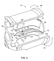
- FIG. 5 is a perspective cutaway view of an embodiment of the fuel nozzle 14 taken within arcuate line 5-5 of FIG. 4 .
- the fuel nozzle 14 includes the swirl vanes 70 disposed circumferentially around the nozzle center body 62, wherein the swirl vanes 70 extend radially outward from the nozzle center body 62 to the outer peripheral wall 60.
- each swirl vane 70 is a hollow body (e.g., a hollow airfoil shaped body) having the outlet chamber 92 from which fuel may be injected into the flow of air. The fuel travels upstream to the outlet chamber 92, and then exits the outlet chamber 92 through the fuel injection ports 98.
- the swirl vanes 70 are configured to swirl the flow, and thus induce air-fuel mixing, in a circumferential direction 80 about the axis 76.
- each swirl vane 70 bends or curves from an upstream end portion 104 to a downstream end portion 106.
- the upstream end portion 104 is generally oriented in an axial direction along the axis 76
- the downstream end portion 106 is generally angled, curved, or directed away from the axial direction along the axis 76.
- the downstream end portion 106 of each swirl vane 70 biases or guides the flow into a rotational path about the axis 76 (e.g., swirling flow).
- Each swirl vane 70 may include the fuel injection ports 98 on first and/or second sides 108, 110 of the swirl vane 70.
- the first and second sides 108, 110 may combine to form the outer surface of the swirl vane 70.
- the first and second sides 108, 110 may define an airfoil shaped surface.
- the physical shape of the swirl vanes 70 of the fuel nozzle 14 may induce swirling of the air-fuel mixture in a circumferential direction about the longitudinal centerline of the fuel nozzle 14, as indicated by arrow 114. More specifically, the downstream end portion 106 of each swirl vane 70 may bias or guide the air-fuel mixture into a rotational path about the axis 76 (e.g., swirling flow). Although illustrated in FIG. 5 as inducing counterclockwise rotational swirling relative to the axis 76, in other embodiments, the swirling vanes 70 of the fuel nozzle 14 may be designed such that clockwise rotational swirling relative to the axis 76 is induced. Indeed, the bi-directional fuel injection embodiments described herein may be extended to other systems that inject a flow of fuel into a flow of air.
- other fuel injection ports of the fuel nozzle 14 may utilize the bi-directional fuel injection techniques described herein.
- a plurality of fuel injection ports 112 through the nozzle center body 62 of the fuel nozzle 14 may utilize the bi-directional fuel injection techniques described herein to inject the flow of fuel into the flow of air.
- the fuel injection ports 98, 112 may be collectively referred to as the bi-directional fuel injection ports 116.
- FIG. 6 is a cross-sectional side view of an embodiment of a bi-directional fuel injection port 116 (e.g., the fuel injection ports 98, 112) of the fuel nozzles 14 described above.
- the fuel 118 flows through a wall 120 (e.g., a wall of the swirling vanes 70 for the fuel injection ports 98, and a wall of the nozzle center body 62 for the fuel injection ports 112) from an inner side 122 of the wall 120 to an outer side 124 of the wall 120.
- the fuel injection port 116 may have a central axis 126 of fuel flow that is angled with respect to the wall 120.
- the central axis 126 of fuel flow is not orthogonal to the wall 120, extending generally perpendicular to the inner and outer sides 122, 124 of the wall 120. Rather, the central axis 126 of fuel flow may be aligned at an angle ⁇ from both the inner and outer sides 122, 124 of the wall 120.
- the angle ⁇ may be approximately 15, 20, 25, 30, 35, 40, or 45 degrees, or even greater.
- the bi-directional fuel injection techniques may be extended to fuel injection ports 116 that are aligned substantially orthogonally to the wall 120.
- the fuel injection port 116 may include more than one cross-sectional section.
- the cross-sectional area of the fuel injection port 116 along the central axis 126 of fuel flow may not be constant. More specifically, as illustrated in FIG. 6 , the fuel injection port 116 may include an upstream cross-sectional section 128 and a downstream cross-sectional section 130.
- the upstream cross-sectional section 128 may extend from an upstream end 132 (i.e., an inlet) of the fuel injection port 116 to a central point 134 along the central axis 126 of fuel flow of the fuel injection port 116, whereas the downstream cross-sectional section 130 may extend from the central point 134 along the central axis 126 of fuel flow of the fuel injection port 116 to a downstream end 136 (e.g., an outlet) of the fuel injection port 116.
- the upstream cross-sectional section 128 of the fuel injection port 116 may be substantially constant. More specifically, in certain embodiments, the upstream cross-sectional section 128 may be a substantially constant circular area (e.g., varying only within a range of approximately ⁇ 10%, ⁇ 5%, ⁇ 2%, ⁇ 1%, or even less). However, in other embodiments, the upstream cross-sectional section 128 may be a substantially constant oval area. In addition, in other embodiments, the upstream cross-sectional section 128 may not be substantially constant. For example, the upstream cross-sectional section area 128 may gradually increase along the central axis 126 of fuel flow.
- the downstream cross-sectional section 130 may generally increase (i.e., function as a diffuser section) along the central axis 126 of fuel flow toward the downstream end 136 (e.g., the outlet) of the fuel injection port 116. More specifically, the height h DCS of the downstream cross-sectional section 130 may gradually increase (i.e., diverge) along the central axis 126 of fuel flow toward the downstream end 136 of the fuel injection port 116.
- FIG. 7 is a cross-sectional top view of an embodiment of the bi-directional fuel injection port 116 taken along the central axis 126 of fuel flow illustrated in FIG. 6 .
- the width w DCS of the downstream cross-sectional section 130 may increase (i.e., diverge) significantly more from a first side 138 of the fuel injection port 116 to a second side 140 of the fuel injection port 116 than the height h DCS of the downstream cross-sectional section 130 along the central axis 126 of fuel flow toward the downstream end 136 of the fuel injection port 116.
- the fuel injection port 116 may be in fluid connection with first and second pressure feedback lines 142, 144, which are disposed entirely within the wall 120.
- the first pressure feedback line 142 is on the first side 138 of the fuel injection port 116 and the second pressure feedback line 144 is on the second side 140 of the fuel injection port 116.
- Both the first and second pressure feedback lines 142, 144 include respective pressure feedback inlets 146, 148 and pressure feedback outlets 150, 152.
- the fuel injection port 116 comprises a single, continuous fuel passage having a single inlet and a single outlet for injecting a main fuel flow stream 154 into the flow of air.
- the first and second pressure feedback lines 142, 144 both comprise a single, continuous fuel feedback passage having a single inlet and a single outlet for feeding back a portion of the main fuel flow stream 154.
- the pressure feedback inlets 146, 148 and the pressure feedback outlets 150, 152 are all substantially orthogonal to the central axis 126 of the main fuel flow stream 154.
- a portion of the main fuel flow stream 154 may feed back through the first and second pressure feedback lines 142, 144 in an alternating manner (e.g., first through the first pressure feedback line 142, then through the second pressure feedback line 144, and so forth) to ensure that the main fuel flow stream 154 does not hold against either side 138, 140 of the fuel injection port 116.
- the first and second pressure feedback lines 142, 144 may cause the main fuel flow stream 154 to oscillate back and forth between the first and second sides 138, 140 of the fuel injection port 116, as illustrated by arrows 156.
- the fuel injection port 116 is a bi-directional fuel injection port, which generates a bi-directional oscillating fluidic jet of the main fuel flow stream 154.
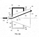
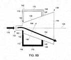
- FIGS. 8A and 8B are cross-sectional top views of an embodiment of the bi-directional fuel injection port 116 as illustrated in FIG. 7 , illustrating the functionality of the first and second pressure feedback lines 142, 144.
- FIG. 8A when the main fuel flow stream 154 attaches to the first side 138 of the fuel injection port 116, a portion of the main fuel flow stream 154 may be induced by a pressure recovery field in the first pressure feedback line 142 to enter the pressure feedback inlet 146 along the first side 138 and exit the pressure feedback outlet 150 along the first side 138.
- a secondary fuel flow stream i.e., a first pressure feedback stream 158) may be induced back through the first pressure feedback line 142.
- the first pressure feedback stream 158 When the first pressure feedback stream 158 exits through the pressure feedback outlet 150 along the first side 138 of the fuel injection port 116, the first pressure feedback stream 158 applies pressure against the main fuel flow stream 154 generally orthogonal to the central axis 126. As such, the main fuel flow stream 154 may be forced back toward the central axis 126 by the first pressure feedback stream 158, as illustrated by arrow 160. Indeed, the main fuel flow stream 154 may ultimately be forced all the way back toward the second side 140 of the fuel injection port 116. It is the recovery pressure inside the first pressure feedback line 142 that causes the high pressure at the pressure feedback outlet 150 along the first side 138 of the fuel injection port 116.
- the first pressure feedback line 142 is sized large enough (i.e., with sufficient volume, diameter, and so forth) to ensure that the pressure recovery (i.e., due to lower velocities) in the first pressure feedback line 142 is realized from the dynamic pressure in the fuel injection port 116.
- a portion of the main fuel flow stream 154 may be induced by a pressure recovery field in the second pressure feedback line 144 to enter the pressure feedback inlet 148 along the second side 140 and exit the pressure feedback outlet 152 along the second side 140.
- a secondary fuel flow stream i.e., a second pressure feedback stream 162
- the second pressure feedback stream 162 exits through the pressure feedback outlet 152 along the second side 140 of the fuel injection port 116, the second pressure feedback stream 162 applies pressure against the main fuel flow stream 154 generally orthogonal to the central axis 126.
- the main fuel flow stream 154 may be forced back toward the central axis 126 by the second pressure feedback stream 162, as illustrated by arrow 164. Indeed, the main fuel flow stream 154 may ultimately be forced all the way back toward the first side 138 of the fuel injection port 116. It is the recovery pressure inside the second pressure feedback line 144 that causes the high pressure at the pressure feedback outlet 152 along the second side 140 of the fuel injection port 116. As such, the second pressure feedback line 144 is sized large enough (i.e., with sufficient volume, diameter, and so forth) to ensure that the pressure recovery (i.e., due to lower velocities) in the second pressure feedback line 144 is realized from the dynamic pressure in the fuel injection port 116.
- the first and second pressure feedback lines 142, 144 also passively create an oscillating bi-directional fluidic jet (i.e., illustrated by arrows 156) of the main fuel flow stream 154 such that the main fuel flow stream 154 mixes more efficiently with the air stream.
- the first and second pressure feedback lines 142, 144 passively create the bi-directional oscillating nature of the main fuel flow stream 154.
- the bi-directional oscillations created by the first and second pressure feedback lines 142, 144 also dampen acoustic coupling effects within the combustor 12.
- all fuel injection ports generate substantially similar combustion acoustics due to the fact that the fuel injection ports are generally similarly shaped and oriented.
- first and second pressure feedback lines 142, 144 described herein may be sized and shaped to create different frequencies of oscillation.
- the cross-sectional areas of both the first and second pressure feedback lines 142, 144 are substantially constant across the length of the first and second pressure feedback lines 142, 144.
- the cross-sectional areas and the lengths of both the first and second pressure feedback lines 142, 144 are substantially similar to ensure that the oscillations between the first and second sides 138, 140 of the fuel injection port 116 occur at generally the same frequencies.
- both the cross-sectional areas and the lengths of the first and second pressure feedback lines 142, 144 associated with the fuel injection ports 116 may be varied between fuel injection ports 116 to create different frequencies of oscillation for the fuel injection ports 116.
- higher recovered pressure is obtained by larger cross-sectional areas of the first and second pressure feedback lines 142, 144.
- the lengths of the first and second pressure feedback lines 142, 144 may be varied as an additional parameter to modify the frequency of oscillation for a given fuel injection port 116.
- the cross-sectional areas and/or the lengths of the associated first and second pressure feedback lines 142, 144 may be varied to tune the frequency of oscillation for the fuel injection port 116.
- the cross-sectional areas and/or the lengths of the first and second pressure feedback lines 142, 144 may be sized based on an expected flow rate of the main fuel flow stream 154 through the fuel injection port 116.
- the cross-sectional areas and/or lengths of the first and second pressure feedback lines 142, 144 for all of the fuel injection ports 116 (e.g., the fuel injection ports 98, 112) of a given fuel nozzle 14 may be modified to ensure that none of the fuel injection ports 116 have exactly the same frequency of oscillation.
- all of the various oscillation frequencies for the fuel injection ports 116 may be designed to not coincide with the combustion frequencies present in the combustor 12. As described above, in conventional combustion systems, heat releases in the combustor generate certain magnitudes of dynamic pressure at predominant frequencies that can cause detrimental effects to the combustor.
- pressure oscillations can be acoustically coupled to the upstream fuel injection, causing a detrimental feedback loop that varies the fuel injection flow rate.
- the system is acoustically decoupled.
- FIGS. 9A and 9B are cross-sectional top views of an embodiment of the bi-directional fuel injection port 116 as illustrated in FIG. 7 , illustrating varying lengths of the bi-directional fuel injection port 116. More specifically, as illustrated in FIGS. 9A , the length l DCS of the downstream cross-sectional section 130 of the fuel injection port 116 may be varied. In particular, in the embodiment illustrated in FIG. 9A , the length l DCS of the downstream cross-sectional section 130 is relatively long with the pressure feedback inlets 146, 148 farther away from the downstream end 136. Conversely, in the embodiment illustrated in FIG. 9B , the length l DCS of the downstream cross-sectional section 130 is relatively short with the pressure feedback inlets 146, 148 closer to the downstream end 136.
- the length l DCS of the downstream cross-sectional section 130 of the fuel injection port 116 is relatively long and, as such, a fully diffused flow regime 166 (e.g., caused by the bi-directional oscillating nature of the main fuel flow stream 154) occurs farther away from the downstream end 136 than in the embodiment illustrated in FIG. 9B , where the length l DCS of the downstream cross-sectional section 130 is relatively small.
- a fully diffused flow regime 166 e.g., caused by the bi-directional oscillating nature of the main fuel flow stream 15
- the location of the fully diffused flow regime 166 may be varied, and the mixing dynamics with the flow of air may also be varied.
- both of the first and second pressure feedback lines 142, 144 include three substantially orthogonal sections 168, 170, 172.
- the first and second pressure feedback lines 142, 144 may be shaped differently than three substantially orthogonal sections 168, 170, 172.
- first and second pressure feedback lines 142, 144 may be rounded, such as circular or oval, with the end points (e.g., the pressure feedback inlets 146, 148 and the pressure feedback outlets 150, 152) of the circular or oval shapes still be substantially orthogonal to the central axis 126 of the main fuel flow stream 154.
- the walls 120 are rapid prototyped such that the fuel injection ports 116 and associated first and second pressure feedback lines 142, 144 are not drilled into the walls 120.
- the varying shapes of the upstream and downstream cross-sectional sections 128, 130 of the fuel injection ports 116 and the varying shapes (e.g., varying cross-sectional areas and/or lengths) of the first and second pressure feedback lines 142, 144 are more easily created in the walls 120.
- the rapid prototyping also facilitates the modification of the cross-sectional areas and lengths of the upstream and downstream cross-sectional sections 128, 130 of the fuel injection ports 116 and the first and second pressure feedback lines 142, 144 to vary the oscillation acoustics among the various fuel injection ports 116 as described above.
Landscapes
- Engineering & Computer Science (AREA)
- Chemical & Material Sciences (AREA)
- Combustion & Propulsion (AREA)
- Mechanical Engineering (AREA)
- General Engineering & Computer Science (AREA)
- Fuel-Injection Apparatus (AREA)
Abstract
A fuel injector includes a wall separating a fuel passage from an air passage. The fuel injector also includes a fuel injection port (116) extending from a first side of the wall to a second side of the wall for injecting a flow of fuel from the fuel passage into a flow of air in the air passage. In addition, the fuel injector includes first (142) and second (144) feedback lines extending from a downstream end (136) of the fuel injection port (116) to an upstream end (132) of the fuel injection port (116). The first (142) and second (144) feedback lines are disposed on opposite sides of the fuel injection port (116). In addition, the first (142) and second (144) feedback lines are disposed entirely within the wall.
Description
- The subject matter disclosed herein relates to fuel nozzles and, more specifically, to fuel nozzles having passive bi-directional oscillating fuel injection ports.
- A gas turbine engine combusts a mixture of fuel and air to generate hot combustion gases, which in turn drive one or more turbines. In particular, the hot combustion gases force turbine blades to rotate, thereby driving a shaft to rotate one or more loads, e.g., electrical generator. As appreciated, a flame may develop in a combustion zone having a combustible mixture of fuel and air. Unfortunately, the flame can potentially propagate upstream from the combustion zone into the fuel nozzle, which can result in damage due to the heat of combustion. This phenomenon is generally referred to as flashback. Likewise, the flame can sometimes develop on or near surfaces, which can also result in damage due to the heat of combustion. This phenomenon is generally referred to as flame holding. For example, the flame holding may occur on or near a fuel nozzle in a low velocity region. In particular, an injection of a fuel flow into an air flow may cause a low velocity region near the injection point of the fuel flow, which can lead to flame holding. In addition, conventional combustion systems are often characterized by high degrees of acoustic coupling, whereby heat releases in the combustor generate certain magnitudes of dynamic pressure at predominant frequencies that may cause detrimental effects to the combustor.
- Certain embodiments commensurate in scope with the originally claimed invention are summarized below. These embodiments are not intended to limit the scope of the claimed invention, but rather these embodiments are intended only to provide a brief summary of possible forms of the invention. Indeed, the invention may encompass a variety of forms that may be similar to or different from the embodiments set forth below.
- In a first aspect, the invention resides in a fuel injector including a wall separating a fuel passage from an air passage. The fuel injector also includes a fuel injection port extending from a first side of the wall to a second side of the wall for injecting a flow of fuel from the fuel passage into a flow of air in the air passage. In addition, the fuel injector includes first and second feedback lines extending from a downstream end of the fuel injection port to an upstream end of the fuel injection port. The first and second feedback lines are disposed on opposite sides of the fuel injection port. In addition, the first and second feedback lines are disposed entirely within the wall.
- In a second aspect, the invention resides in a fuel nozzle including a fuel passage through which a fuel flows, an air passage through which air flows, and the fuel injection as described above.
- In a third aspect, the invention resides in a method including injecting a main flow of fuel along a central axis of a fuel injection port. In addition, the method includes passively inducing a first feedback flow of fuel through a first feedback line extending from a downstream end on a first side of the fuel injection port to an upstream end on the first side of the fuel injection port. The first feedback flow of fuel creates a pressure field that forces the main flow of fuel toward a second side of the fuel injection port opposite the first side.
- Embodiments of the present invention will now be described, by way of example only, with reference to the accompanying drawings in which:
-
FIG. 1 is a schematic flow diagram of an embodiment of a turbine system having a combustor with a plurality of fuel nozzles, which may include bi-directional fuel injection ports; -
FIG. 2 is a cross-sectional side view of an embodiment of the turbine system, as illustrated inFIG. 1 ; -
FIG. 3 is a perspective view of an embodiment of a combustor head end of a combustor of the gas turbine engine, as shown inFIG. 2 , illustrating the plurality of fuel nozzles; -
FIG. 4 is a cross-sectional side view of an embodiment of a fuel nozzle, as shown inFIG. 3 ; -
FIG. 5 is a perspective cutaway view of an embodiment of the fuel nozzle, as shown inFIG. 4 ; -
FIG. 6 is a cross-sectional side view of an embodiment of a bi-directional fuel injection port of the fuel nozzles; -
FIG. 7 is a cross-sectional top view of an embodiment of the bi-directional fuel injection port taken along a central axis of fuel flow illustrated inFIG. 6 ; -
FIGS. 8A and8B are cross-sectional top views of an embodiment of the bi-directional fuel injection port as illustrated inFIG. 7 , illustrating the functionality of first and second pressure feedback lines; and -
FIGS. 9A and 9B are cross-sectional top views of an embodiment of the bi-directional fuel injection port as illustrated inFIG. 7 , illustrating varying lengths of the bi-directional fuel injection port. - One or more specific embodiments of the present invention will be described below. In an effort to provide a concise description of these embodiments, all features of an actual implementation may not be described in the specification. It should be appreciated that in the development of any such actual implementation, as in any engineering or design project, numerous implementation-specific decisions must be made to achieve the developers' specific goals, such as compliance with system-related and business-related constraints, which may vary from one implementation to another. Moreover, it should be appreciated that such a development effort might be complex and time consuming, but would nevertheless be a routine undertaking of design, fabrication, and manufacture for those of ordinary skill having the benefit of this disclosure.
- When introducing elements of various embodiments of the present invention, the articles "a," "an," "the," and "said" are intended to mean that there are one or more of the elements. The terms "comprising," "including," and "having" are intended to be inclusive and mean that there may be additional elements other than the listed elements.
- The disclosed embodiments include systems and methods for passively inducing bi-directional oscillating fuel injection in combustion systems, such as in pre-mixed combustion systems for gas turbines. The embodiments described herein include fuel injection ports, each having a diffuser section disposed in a wall, and two pressure feedback lines on opposite sides of the fuel injection port. When the fuel attaches to one of the sides of the fuel injection port, a feedback flow is generated through the pressure feedback line on that side of the fuel injection port, such that a high pressure is created at the outlet of the pressure feedback line, thereby forcing the fuel stream back toward the opposite wall. This process repeats in an alternating manner, thereby creating the bi-directional oscillating nature of the fuel stream. The resulting oscillating fuel injection jet is output from the diffuser section of the fuel injection port without detachment and flame holding. In addition, the self-oscillating (i.e., passive) nature of the fuel injection decouples the fuel injection acoustics from other acoustic excited modes in the combustor. Furthermore, since each fuel injection port may have a different oscillating frequency by varying dimensions (i.e., shapes, sizes, orientations, and so forth) of the fuel injection ports, the probability of any acoustic driven coupling is relatively small.
-
FIG. 1 is a schematic flow diagram of an embodiment of aturbine system 10 having acombustor 12 with a plurality offuel nozzles 14. As illustrated, the plurality offuel nozzles 14 may include first, second, andthird fuel nozzles fuel nozzles 14 may include 2, 4, 5, 6, 7, 8, 9, 10, 11, 12, or evenmore fuel nozzles 14. Theturbine system 10 may use liquid or gas fuel, such as natural gas and/or a hydrogen rich synthetic gas. As depicted, thefuel nozzles 14 intake a plurality offuel supply streams fuel supply streams combustor 12. More specifically, as described in greater detail below, each of thefuel nozzles 14 may include passive bi-directional oscillating fuel injection features to facilitate the creation of oscillating fluid jets of the fuel into the air, thereby reducing the possibility of ignition and flame holding at locations where the fuel mixes with the air. - The air-fuel mixture combusts in a chamber within the
combustor 12, thereby creating hot pressurized exhaust gases. Thecombustor 12 directs the exhaust gases through aturbine 28 toward anexhaust outlet 30. As the exhaust gases pass through theturbine 28, the gases force one or more turbine blades to rotate ashaft 32 along an axis of theturbine system 10. As illustrated, theshaft 32 may be connected to various components of theturbine system 10, including acompressor 34. Thecompressor 34 also includes blades that may be coupled to theshaft 32. As theshaft 32 rotates, the blades within thecompressor 34 also rotate, thereby compressing air from anair intake 36 through thecompressor 34 and into thefuel nozzles 14 and/orcombustor 12. More specifically, a firstcompressed air stream 38 may be directed into thefirst fuel nozzle 16, a secondcompressed air stream 40 may be directed into thesecond fuel nozzle 18, and a thirdcompressed air stream 42 may be directed into thethird fuel nozzle 20. However, again, any number of compressed air streams 44 may be directed into the plurality ofrespective fuel nozzles 14. Theshaft 32 may also be connected to aload 46, which may be a vehicle or a stationary load, such as an electrical generator in a power plant or a propeller on an aircraft, for example. Theload 46 may include any suitable device capable of being powered by the rotational output ofturbine system 10. -
FIG. 2 is a cross-sectional side view of an embodiment of theturbine system 10, as illustrated inFIG. 1 . Theturbine system 10 includes one ormore fuel nozzles 14 located inside one ormore combustors 12. In operation, air enters theturbine system 10 through theair intake 36 and is pressurized in thecompressor 34. The compressed air may then be mixed with fuel for combustion within thecombustor 12 using thefuel nozzles 14 having the bi-directional fuel injection ports described herein. For example, thefuel nozzles 14 may inject a fuel-air mixture into thecombustor 12 in a suitable ratio for optimal combustion, emissions, fuel consumption, and power output. The combustion generates hot pressurized exhaust gases, which then drive one ormore blades 48 within theturbine 28 to rotate theshaft 32 and, thus, thecompressor 34 and theload 46. The rotation of theturbine blades 48 causes a rotation of theshaft 32, thereby causingblades 50 within thecompressor 34 to draw in and pressurize the air received by theair intake 36. -
FIG. 3 is a detailed perspective view of an embodiment of acombustor head end 52 having anend cover 54 with the plurality offuel nozzles 14 attached to an endcover base surface 56 via sealing joints 58. Thehead end 52 routes the compressed air from thecompressor 34 and the fuel through theend cover 54 to each of thefuel nozzles 14, which at least partially pre-mix the compressed air and fuel as an air-fuel mixture prior to entry into a combustion zone in thecombustor 12. As described in greater detail below, eachfuel nozzle 14 may include a swirling mechanism (e.g., one or more swirl vanes) configured to induce swirl in an air-fuel mixture (or, in certain circumstances, only air) in a direction. In addition, as also described in greater detail below, thefuel nozzles 14 may include bi-directional fuel injection features to facilitate the creation of oscillating fluid jets of the fuel into the air. -
FIG. 4 is a cross-sectional side view of an embodiment of thefuel nozzles 14 ofFIG. 3 . In the illustrated embodiment, thefuel nozzle 14 includes an outerperipheral wall 60 and anozzle center body 62 disposed within the outerperipheral wall 60. The outerperipheral wall 60 may be described as a burner tube, whereas thenozzle center body 62 may be described as a fuel supply tube. Thefuel nozzle 14 also includes an air-fuel pre-mixer 64, anair inlet 66, afuel inlet 68,swirl vanes 70, a mixing passage 72 (e.g., annular passage for mixing air and fuel), and afuel passage 74. The swirl vanes 70 are configured to induce swirling flow within thefuel nozzle 14. It should be noted that various aspects of thefuel nozzle 14 may be described with reference to an axial direction oraxis 76, a radial direction oraxis 78, and a circumferential direction oraxis 80. For example, theaxis 76 corresponds to a longitudinal centerline or lengthwise direction, theaxis 78 corresponds to a crosswise or radial direction relative to the longitudinal centerline, and theaxis 80 corresponds to the circumferential direction about the longitudinal centerline. - As illustrated, fuel may enter the
nozzle center body 62 through thefuel inlet 68 into thefuel passage 74. The fuel may travel axially 76 in a downstream direction, as noted byarrow 82, through the entire length of thenozzle center body 62 until it impinges upon an interior end wall 84 (e.g., a downstream end portion) of thefuel passage 74, whereupon the fuel reverses flow, as indicated byarrow 86, and enters areverse flow passage 88 in an upstream axial direction. For purposes of discussion, the term downstream may represent a direction of flow of the combustion gases through thecombustor 12 toward theturbine 28, whereas the term upstream may represent a direction away from or opposite to the direction of flow of the combustion gases through thecombustor 12 toward theturbine 28. - At the axially 76 extending end of the
reverse flow passage 88 opposite theend wall 84, the fuel impinges upon wall 90 (e.g., upstream end portion) and travels into an outlet chamber 92 (e.g., an upstream cavity or passage), as indicated byarrow 94. The fuel is expelled from theoutlet chamber 92 throughfuel injection ports 98 in theswirl vanes 70, where the fuel mixes with air flowing through the mixingpassage 72 from theair inlet 66, as illustrated byarrow 100. For example, thefuel injection ports 98 may inject the fuel crosswise to the air flow to induce mixing. Likewise, theswirl vanes 70 induce a swirling flow of the air and fuel, thereby increasing the mixture of the air and fuel. In addition, as described in greater detail below, thefuel injection ports 98 may be configured to facilitate bi-directional fuel injection of the fuel into the flow of air. The air-fuel mixture exits the air-fuel pre-mixer 64 and continues to mix as it flows through the mixingpassage 72, as indicated byarrow 102. This continuing mixing of the air and fuel through the mixingpassage 72 allows the air-fuel mixture exiting the mixingpassage 72 to be substantially fully mixed when it enters thecombustor 12, where the mixed air and fuel may be combusted. -
FIG. 5 is a perspective cutaway view of an embodiment of thefuel nozzle 14 taken within arcuate line 5-5 ofFIG. 4 . Thefuel nozzle 14 includes theswirl vanes 70 disposed circumferentially around thenozzle center body 62, wherein theswirl vanes 70 extend radially outward from thenozzle center body 62 to the outerperipheral wall 60. As illustrated, eachswirl vane 70 is a hollow body (e.g., a hollow airfoil shaped body) having theoutlet chamber 92 from which fuel may be injected into the flow of air. The fuel travels upstream to theoutlet chamber 92, and then exits theoutlet chamber 92 through thefuel injection ports 98. - The swirl vanes 70 are configured to swirl the flow, and thus induce air-fuel mixing, in a
circumferential direction 80 about theaxis 76. As illustrated, eachswirl vane 70 bends or curves from anupstream end portion 104 to adownstream end portion 106. In particular, theupstream end portion 104 is generally oriented in an axial direction along theaxis 76, whereas thedownstream end portion 106 is generally angled, curved, or directed away from the axial direction along theaxis 76. As a result, thedownstream end portion 106 of eachswirl vane 70 biases or guides the flow into a rotational path about the axis 76 (e.g., swirling flow). This swirling flow enhances air-fuel mixing within thefuel nozzle 14 prior to delivery into thecombustor 12. Eachswirl vane 70 may include thefuel injection ports 98 on first and/orsecond sides swirl vane 70. The first andsecond sides swirl vane 70. For example, the first andsecond sides - Therefore, as described above, the physical shape of the
swirl vanes 70 of thefuel nozzle 14 may induce swirling of the air-fuel mixture in a circumferential direction about the longitudinal centerline of thefuel nozzle 14, as indicated byarrow 114. More specifically, thedownstream end portion 106 of eachswirl vane 70 may bias or guide the air-fuel mixture into a rotational path about the axis 76 (e.g., swirling flow). Although illustrated inFIG. 5 as inducing counterclockwise rotational swirling relative to theaxis 76, in other embodiments, the swirlingvanes 70 of thefuel nozzle 14 may be designed such that clockwise rotational swirling relative to theaxis 76 is induced. Indeed, the bi-directional fuel injection embodiments described herein may be extended to other systems that inject a flow of fuel into a flow of air. - Moreover, in addition to the
fuel injection ports 98 of the swirlingvanes 70 illustrated inFIGS. 4 and5 , other fuel injection ports of thefuel nozzle 14 may utilize the bi-directional fuel injection techniques described herein. For example, as illustrated inFIG. 5 , a plurality offuel injection ports 112 through thenozzle center body 62 of thefuel nozzle 14 may utilize the bi-directional fuel injection techniques described herein to inject the flow of fuel into the flow of air. As such, thefuel injection ports fuel injection ports 116. -
FIG. 6 is a cross-sectional side view of an embodiment of a bi-directional fuel injection port 116 (e.g., thefuel injection ports 98, 112) of thefuel nozzles 14 described above. For each of the types of bi-directionalfuel injection ports 116 described above, thefuel 118 flows through a wall 120 (e.g., a wall of the swirlingvanes 70 for thefuel injection ports 98, and a wall of thenozzle center body 62 for the fuel injection ports 112) from aninner side 122 of thewall 120 to anouter side 124 of thewall 120. As illustrated inFIG. 6 , in certain embodiments, thefuel injection port 116 may have acentral axis 126 of fuel flow that is angled with respect to thewall 120. In other words, thecentral axis 126 of fuel flow is not orthogonal to thewall 120, extending generally perpendicular to the inner andouter sides wall 120. Rather, thecentral axis 126 of fuel flow may be aligned at an angle θ from both the inner andouter sides wall 120. For example, in certain embodiments, the angle θ may be approximately 15, 20, 25, 30, 35, 40, or 45 degrees, or even greater. However, in other embodiments, the bi-directional fuel injection techniques may be extended tofuel injection ports 116 that are aligned substantially orthogonally to thewall 120. - In addition, in certain embodiments, the
fuel injection port 116 may include more than one cross-sectional section. In other words, the cross-sectional area of thefuel injection port 116 along thecentral axis 126 of fuel flow may not be constant. More specifically, as illustrated inFIG. 6 , thefuel injection port 116 may include an upstreamcross-sectional section 128 and a downstreamcross-sectional section 130. In general, the upstreamcross-sectional section 128 may extend from an upstream end 132 (i.e., an inlet) of thefuel injection port 116 to acentral point 134 along thecentral axis 126 of fuel flow of thefuel injection port 116, whereas the downstreamcross-sectional section 130 may extend from thecentral point 134 along thecentral axis 126 of fuel flow of thefuel injection port 116 to a downstream end 136 (e.g., an outlet) of thefuel injection port 116. - In certain embodiments, the upstream
cross-sectional section 128 of thefuel injection port 116 may be substantially constant. More specifically, in certain embodiments, the upstreamcross-sectional section 128 may be a substantially constant circular area (e.g., varying only within a range of approximately ±10%, ±5%, ±2%, ±1%, or even less). However, in other embodiments, the upstreamcross-sectional section 128 may be a substantially constant oval area. In addition, in other embodiments, the upstreamcross-sectional section 128 may not be substantially constant. For example, the upstreamcross-sectional section area 128 may gradually increase along thecentral axis 126 of fuel flow. - Similarly, as illustrated in
FIG. 6 , the downstreamcross-sectional section 130 may generally increase (i.e., function as a diffuser section) along thecentral axis 126 of fuel flow toward the downstream end 136 (e.g., the outlet) of thefuel injection port 116. More specifically, the height hDCS of the downstreamcross-sectional section 130 may gradually increase (i.e., diverge) along thecentral axis 126 of fuel flow toward thedownstream end 136 of thefuel injection port 116.FIG. 7 is a cross-sectional top view of an embodiment of the bi-directionalfuel injection port 116 taken along thecentral axis 126 of fuel flow illustrated inFIG. 6 . As illustrated, the width wDCS of the downstreamcross-sectional section 130 may increase (i.e., diverge) significantly more from afirst side 138 of thefuel injection port 116 to asecond side 140 of thefuel injection port 116 than the height hDCS of the downstreamcross-sectional section 130 along thecentral axis 126 of fuel flow toward thedownstream end 136 of thefuel injection port 116. - As illustrated in
FIG. 7 , thefuel injection port 116 may be in fluid connection with first and secondpressure feedback lines wall 120. The firstpressure feedback line 142 is on thefirst side 138 of thefuel injection port 116 and the secondpressure feedback line 144 is on thesecond side 140 of thefuel injection port 116. Both the first and secondpressure feedback lines pressure feedback inlets pressure feedback outlets fuel injection port 116 comprises a single, continuous fuel passage having a single inlet and a single outlet for injecting a mainfuel flow stream 154 into the flow of air. Similarly, in certain embodiments, the first and secondpressure feedback lines fuel flow stream 154. - In certain embodiments, the
pressure feedback inlets pressure feedback outlets central axis 126 of the mainfuel flow stream 154. As described in greater detail below, a portion of the mainfuel flow stream 154 may feed back through the first and secondpressure feedback lines pressure feedback line 142, then through the secondpressure feedback line 144, and so forth) to ensure that the mainfuel flow stream 154 does not hold against eitherside fuel injection port 116. Rather, by ensuring that the mainfuel flow stream 154 does not hold against eitherside fuel injection port 116, the first and secondpressure feedback lines fuel flow stream 154 to oscillate back and forth between the first andsecond sides fuel injection port 116, as illustrated byarrows 156. As such, thefuel injection port 116 is a bi-directional fuel injection port, which generates a bi-directional oscillating fluidic jet of the mainfuel flow stream 154. - For example,
FIGS. 8A and8B are cross-sectional top views of an embodiment of the bi-directionalfuel injection port 116 as illustrated inFIG. 7 , illustrating the functionality of the first and secondpressure feedback lines FIG. 8A , when the mainfuel flow stream 154 attaches to thefirst side 138 of thefuel injection port 116, a portion of the mainfuel flow stream 154 may be induced by a pressure recovery field in the firstpressure feedback line 142 to enter thepressure feedback inlet 146 along thefirst side 138 and exit thepressure feedback outlet 150 along thefirst side 138. As such, a secondary fuel flow stream (i.e., a first pressure feedback stream 158) may be induced back through the firstpressure feedback line 142. When the firstpressure feedback stream 158 exits through thepressure feedback outlet 150 along thefirst side 138 of thefuel injection port 116, the firstpressure feedback stream 158 applies pressure against the mainfuel flow stream 154 generally orthogonal to thecentral axis 126. As such, the mainfuel flow stream 154 may be forced back toward thecentral axis 126 by the firstpressure feedback stream 158, as illustrated byarrow 160. Indeed, the mainfuel flow stream 154 may ultimately be forced all the way back toward thesecond side 140 of thefuel injection port 116. It is the recovery pressure inside the firstpressure feedback line 142 that causes the high pressure at thepressure feedback outlet 150 along thefirst side 138 of thefuel injection port 116. As such, the firstpressure feedback line 142 is sized large enough (i.e., with sufficient volume, diameter, and so forth) to ensure that the pressure recovery (i.e., due to lower velocities) in the firstpressure feedback line 142 is realized from the dynamic pressure in thefuel injection port 116. - As illustrated in
FIG. 8B , when the mainfuel flow stream 154 attaches to thesecond side 140 of thefuel injection port 116, a portion of the mainfuel flow stream 154 may be induced by a pressure recovery field in the secondpressure feedback line 144 to enter thepressure feedback inlet 148 along thesecond side 140 and exit thepressure feedback outlet 152 along thesecond side 140. As such, a secondary fuel flow stream (i.e., a second pressure feedback stream 162) may be induced back through the secondpressure feedback line 144. When the secondpressure feedback stream 162 exits through thepressure feedback outlet 152 along thesecond side 140 of thefuel injection port 116, the secondpressure feedback stream 162 applies pressure against the mainfuel flow stream 154 generally orthogonal to thecentral axis 126. As such, the mainfuel flow stream 154 may be forced back toward thecentral axis 126 by the secondpressure feedback stream 162, as illustrated byarrow 164. Indeed, the mainfuel flow stream 154 may ultimately be forced all the way back toward thefirst side 138 of thefuel injection port 116. It is the recovery pressure inside the secondpressure feedback line 144 that causes the high pressure at thepressure feedback outlet 152 along thesecond side 140 of thefuel injection port 116. As such, the secondpressure feedback line 144 is sized large enough (i.e., with sufficient volume, diameter, and so forth) to ensure that the pressure recovery (i.e., due to lower velocities) in the secondpressure feedback line 144 is realized from the dynamic pressure in thefuel injection port 116. - As such, returning now to
FIG. 7 , in addition to ensuring that the mainfuel flow stream 154 does not attach to thesides fuel injection port 116, the first and secondpressure feedback lines fuel flow stream 154 such that the mainfuel flow stream 154 mixes more efficiently with the air stream. In other words, without the use of a separate control system (e.g., to actively vary the flow rate, direction, and so forth of the main fuel flow stream 154), the first and secondpressure feedback lines fuel flow stream 154. In addition, the bi-directional oscillations created by the first and secondpressure feedback lines combustor 12. In conventional fuel injection techniques, all fuel injection ports generate substantially similar combustion acoustics due to the fact that the fuel injection ports are generally similarly shaped and oriented. - However, the first and second
pressure feedback lines pressure feedback lines pressure feedback lines pressure feedback lines second sides fuel injection port 116 occur at generally the same frequencies. However, both the cross-sectional areas and the lengths of the first and secondpressure feedback lines fuel injection ports 116 may be varied betweenfuel injection ports 116 to create different frequencies of oscillation for thefuel injection ports 116. Generally speaking, higher recovered pressure is obtained by larger cross-sectional areas of the first and secondpressure feedback lines pressure feedback lines fuel injection port 116. - As such, for any given
fuel injection port 116, the cross-sectional areas and/or the lengths of the associated first and secondpressure feedback lines fuel injection port 116. In certain embodiments, the cross-sectional areas and/or the lengths of the first and secondpressure feedback lines fuel flow stream 154 through thefuel injection port 116. Furthermore, returning now toFIG. 5 , the cross-sectional areas and/or lengths of the first and secondpressure feedback lines fuel injection ports 98, 112) of a givenfuel nozzle 14 may be modified to ensure that none of thefuel injection ports 116 have exactly the same frequency of oscillation. Furthermore, in certain embodiments, all of the various oscillation frequencies for thefuel injection ports 116 may be designed to not coincide with the combustion frequencies present in thecombustor 12. As described above, in conventional combustion systems, heat releases in the combustor generate certain magnitudes of dynamic pressure at predominant frequencies that can cause detrimental effects to the combustor. These pressure oscillations can be acoustically coupled to the upstream fuel injection, causing a detrimental feedback loop that varies the fuel injection flow rate. By having a range of fuel injection oscillation frequencies, while still at relatively constant fuel flow rates, the system is acoustically decoupled. - In addition, the effects of strong acoustic coupling may be further mitigated by varying the total length of the
fuel injection port 116 along thecentral axis 126. For example,FIGS. 9A and 9B are cross-sectional top views of an embodiment of the bi-directionalfuel injection port 116 as illustrated inFIG. 7 , illustrating varying lengths of the bi-directionalfuel injection port 116. More specifically, as illustrated inFIGS. 9A , the length lDCS of the downstreamcross-sectional section 130 of thefuel injection port 116 may be varied. In particular, in the embodiment illustrated inFIG. 9A , the length lDCS of the downstreamcross-sectional section 130 is relatively long with thepressure feedback inlets downstream end 136. Conversely, in the embodiment illustrated inFIG. 9B , the length lDCS of the downstreamcross-sectional section 130 is relatively short with thepressure feedback inlets downstream end 136. - As such, the length lDCS of the downstream
cross-sectional section 130 of thefuel injection port 116 is relatively long and, as such, a fully diffused flow regime 166 (e.g., caused by the bi-directional oscillating nature of the main fuel flow stream 154) occurs farther away from thedownstream end 136 than in the embodiment illustrated inFIG. 9B , where the length lDCS of the downstreamcross-sectional section 130 is relatively small. As such, by varying the length lDCS of the downstreamcross-sectional section 130 of thefuel injection port 116, the location of the fully diffusedflow regime 166 may be varied, and the mixing dynamics with the flow of air may also be varied. - Returning now to
FIG. 7 , as described above, in certain embodiments, thepressure feedback inlets pressure feedback outlets pressure feedback lines fuel injection ports 116 are all substantially orthogonal to thecentral axis 126 of the mainfuel flow stream 154. In addition, in the embodiments illustrated inFIGS. 7 ,8A ,8B ,9A, and 9B , both of the first and secondpressure feedback lines orthogonal sections pressure feedback lines orthogonal sections pressure feedback lines pressure feedback inlets pressure feedback outlets 150, 152) of the circular or oval shapes still be substantially orthogonal to thecentral axis 126 of the mainfuel flow stream 154. - In certain embodiments, the
walls 120 are rapid prototyped such that thefuel injection ports 116 and associated first and secondpressure feedback lines walls 120. As such, the varying shapes of the upstream and downstreamcross-sectional sections fuel injection ports 116 and the varying shapes (e.g., varying cross-sectional areas and/or lengths) of the first and secondpressure feedback lines walls 120. Furthermore, the rapid prototyping also facilitates the modification of the cross-sectional areas and lengths of the upstream and downstreamcross-sectional sections fuel injection ports 116 and the first and secondpressure feedback lines fuel injection ports 116 as described above. - This written description uses examples to disclose the invention, including the best mode, and also to enable any person skilled in the art to practice the invention, including making and using any devices or systems and performing any incorporated methods. The patentable scope of the invention is defined by the claims, and may include other examples that occur to those skilled in the art. Such other examples are intended to be within the scope of the claims if they have structural elements that do not differ from the literal language of the claims, or if they include equivalent structural elements with insubstantial differences from the literal languages of the claims.
Claims (16)
- A fuel injector, comprising:a wall (120) separating a fuel passage (74) from an air passage (72);a fuel injection port (116) extending from a first side (122) of the wall (120) to a second side (124) of the wall (120) for injecting a flow of fuel (118) from the fuel passage (74) into a flow of air in the air passage (72); andfirst and second feedback lines (142,144) extending from a downstream end (136) of the fuel injection port (116) to an upstream end (132) of the fuel injection port (116), wherein the first and second feedback lines (142,144) are disposed on opposite sides of the fuel injection port (116), and wherein the first and second feedback lines (142,144) are disposed entirely within the wall (120).
- The fuel injector of claim 1, wherein the first and second feedback lines (142,144) are configured to passively induce feedback flows of fuel (118) through the first and second feedback lines (142,144) in an alternating manner such that the flow of fuel (118) through the fuel injection port (116) oscillates from side to side of the fuel injection port (116).
- The fuel injector of claim 1 or 2, wherein a cross-sectional area (128,130) of the fuel injection port (116) increases from the upstream end (132) to the downstream end (136).
- The fuel injector of claim 1, 2 or 3, wherein the first and second feedback lines (142,144) each comprise first and second ends (146,148,150,152) that are substantially orthogonal to a central axis of (126) the flow of fuel (154), wherein the first end (146,148) is proximate to the downstream end (136) of the fuel injection port (116) and the second end (150,152) is proximate to the upstream end (132) of the fuel injection port (116).
- The fuel injector of claim 4, wherein the first and second feedback lines (142,144) comprise only substantially orthogonal sections from the first end (146,148) to the second end (150,152).
- The fuel injector of claim 4 or 5, wherein the first and second feedback lines (142,144) comprise rounded sections from the first end (146,148) to the second end (150,152).
- The fuel injector of any of claims 1 to 6, wherein cross-sectional areas of the first and second feedback lines (142,144) are sized based upon an expected fuel flow rate through the fuel injection port (116).
- The fuel injector of any of claims 1 to 6, wherein lengths of the first and second feedback lines (142,144) are sized based upon an expected fuel flow rate through the fuel injection port (116).
- The fuel injector of any preceding claim, wherein the wall (120) comprises a plurality of fuel injection ports (116), and wherein cross-sectional areas of the first and second feedback lines (142,144) associated with the fuel injection ports (116) vary between fuel injection ports (116).
- The fuel injector of claims 1 to 8, wherein the wall (120) comprises a plurality of fuel injection ports, and wherein lengths of the first and second feedback lines (142,144) associated with the fuel injection ports (116) vary between fuel injection ports (116).
- The fuel injector of any preceding claim, wherein a central axis (126) of the flow of fuel (154) through the fuel injection port (116) is angled with respect to the wall (120).
- A fuel nozzle, (14) comprising:a fuel passage (74) through which a fuel flows (118);an air passage (72) through which air flows; anda fuel injector as recited in any of claims 1 to 11.
- A method, comprising:injecting a main flow of fuel (154) along a central axis (126) of a fuel injection port (116); andpassively inducing a first feedback flow of fuel (118) through a first feedback line (142) extending from a downstream end (136) on a first side (138) of the fuel injection port (116) to an upstream end (132) on the first side (138) of the fuel injection port (116), wherein the first feedback flow of fuel creates a pressure field that forces the main flow of fuel (154) toward a second side (146) of the fuel injection port (116) opposite the first side (138).
- The method of claim 13, comprising passively inducing a second feedback flow of fuel through a second feedback line (144) extending from the downstream end (136) on the second side (146) of the fuel injection port (116) to the upstream end (132) on the second side (146) of the fuel injection port (116), wherein the second feedback flow of fuel creates a pressure that forces the main flow of fuel (154) toward the first side (138) of the fuel injection port (116).
- The method of claim 14, comprising oscillating the main flow of fuel (154) from the first side (138) to the second side (146) of the fuel injection port (116).
- The method of claim 15, comprising oscillating the main flow of fuel (154) between diverging first (138) and second sides (146) of the fuel injection port (116).
Applications Claiming Priority (1)
| Application Number | Priority Date | Filing Date | Title |
|---|---|---|---|
| US13/077,719 US8899494B2 (en) | 2011-03-31 | 2011-03-31 | Bi-directional fuel injection method |
Publications (1)
| Publication Number | Publication Date |
|---|---|
| EP2505920A2 true EP2505920A2 (en) | 2012-10-03 |
Family
ID=45936900
Family Applications (1)
| Application Number | Title | Priority Date | Filing Date |
|---|---|---|---|
| EP12161137A Withdrawn EP2505920A2 (en) | 2011-03-31 | 2012-03-23 | Fuel injector having passive bi-directional oscillating fuel injection ports |
Country Status (3)
| Country | Link |
|---|---|
| US (1) | US8899494B2 (en) |
| EP (1) | EP2505920A2 (en) |
| CN (1) | CN102777930A (en) |
Families Citing this family (3)
| Publication number | Priority date | Publication date | Assignee | Title |
|---|---|---|---|---|
| JP6327826B2 (en) * | 2013-10-11 | 2018-05-23 | 川崎重工業株式会社 | Gas turbine fuel injection device |
| KR102359001B1 (en) * | 2014-08-26 | 2022-02-08 | 존 징크 컴파니 엘엘씨 | Swirl stabilized high capacity duct burner |
| US10228140B2 (en) * | 2016-02-18 | 2019-03-12 | General Electric Company | Gas-only cartridge for a premix fuel nozzle |
Family Cites Families (17)
| Publication number | Priority date | Publication date | Assignee | Title |
|---|---|---|---|---|
| GB8603759D0 (en) * | 1986-02-15 | 1986-03-19 | Northern Eng Ind | Liquid fuel atomiser |
| DE4215763C2 (en) * | 1992-05-13 | 1996-01-11 | Ppv Verwaltungs Ag | burner |
| DE19752851C1 (en) * | 1997-11-28 | 1998-12-17 | Siemens Ag | Hydraulic 2/2-way control valve for automobile fuel injection system |
| GB2385095B (en) | 2002-01-23 | 2005-11-09 | Alstom | Fluidic apparatuses |
| US7128082B1 (en) | 2005-08-10 | 2006-10-31 | General Electric Company | Method and system for flow control with fluidic oscillators |
| US7669405B2 (en) | 2005-12-22 | 2010-03-02 | General Electric Company | Shaped walls for enhancement of deflagration-to-detonation transition |
| US20070237627A1 (en) | 2006-03-31 | 2007-10-11 | Bunker Ronald S | Offset blade tip chord sealing system and method for rotary machines |
| DE102006023470A1 (en) * | 2006-05-18 | 2007-11-22 | Siemens Ag | Common rail injection system |
| US8001761B2 (en) * | 2006-05-23 | 2011-08-23 | General Electric Company | Method and apparatus for actively controlling fuel flow to a mixer assembly of a gas turbine engine combustor |
| US20080104961A1 (en) | 2006-11-08 | 2008-05-08 | Ronald Scott Bunker | Method and apparatus for enhanced mixing in premixing devices |
| US7832212B2 (en) | 2006-11-10 | 2010-11-16 | General Electric Company | High expansion fuel injection slot jet and method for enhancing mixing in premixing devices |
| US20080134685A1 (en) | 2006-12-07 | 2008-06-12 | Ronald Scott Bunker | Gas turbine guide vanes with tandem airfoils and fuel injection and method of use |
| US20100011770A1 (en) | 2008-07-21 | 2010-01-21 | Ronald James Chila | Gas Turbine Premixer with Cratered Fuel Injection Sites |
| US20100068066A1 (en) | 2008-09-12 | 2010-03-18 | General Electric Company | System and method for generating modulated pulsed flow |
| US20100123031A1 (en) | 2008-11-17 | 2010-05-20 | Caterpillar Inc. | Fluid oscillator assembly for fuel injectors and fuel injection system using same |
| US20110005334A1 (en) | 2009-07-08 | 2011-01-13 | General Electric Company | Tunable fluid flow control system |
| US8763400B2 (en) | 2009-08-04 | 2014-07-01 | General Electric Company | Aerodynamic pylon fuel injector system for combustors |
-
2011
- 2011-03-31 US US13/077,719 patent/US8899494B2/en active Active
-
2012
- 2012-03-23 EP EP12161137A patent/EP2505920A2/en not_active Withdrawn
- 2012-03-30 CN CN2012101039033A patent/CN102777930A/en active Pending
Non-Patent Citations (1)
| Title |
|---|
| None |
Also Published As
| Publication number | Publication date |
|---|---|
| CN102777930A (en) | 2012-11-14 |
| US8899494B2 (en) | 2014-12-02 |
| US20120248217A1 (en) | 2012-10-04 |
Similar Documents
| Publication | Publication Date | Title |
|---|---|---|
| CN205481129U (en) | A fuel injector for gas turbine engine's combustor | |
| CN206113000U (en) | A fuel injector for gas turbine engine's combustor | |
| US8215116B2 (en) | System and method for air-fuel mixing in gas turbines | |
| CN103375819B (en) | Fuel/air premix system for turbogenerator | |
| EP2631544B1 (en) | Annular Premixed Pilot in Fuel Nozzle | |
| JP4958709B2 (en) | Device for reducing combustor acoustics | |
| EP3211316A1 (en) | Pilot nozzles in gas turbine combustors | |
| CN204678394U (en) | For the fuel injector of gas-turbine unit | |
| CN109804200B (en) | Swirler, combustor assembly, and gas turbine with improved fuel/air mixing | |
| US9297535B2 (en) | Fuel/air mixing system for fuel nozzle | |
| CN102538012B (en) | Self-oscillating fuel injection jets | |
| EP2549189A2 (en) | System for damping oscillations in a turbine combustor | |
| EP2213944A2 (en) | Apparatus for fuel injection in a turbine engine | |
| US20160186662A1 (en) | Pilot nozzle in gas turbine combustor | |
| CN101949540A (en) | ACTIVE CONTROL to flame stabilization and tempering in the turbine burner fuel nozzle | |
| CN106196173B (en) | System and method for controlling combustion dynamics in a combustion system | |
| CN106471313A (en) | Air fuel premixer for low emission gas turbine combustor | |
| CN106662328A (en) | Burner comprising a fluidic oscillator, for a gas turbine, and a gas turbine comprising at least one such burner | |
| US10767866B2 (en) | Micromixer for use with liquid fuel | |
| CN116136308A (en) | Cyclone ferrule plate with pressure drop purge channels | |
| US8881531B2 (en) | Gas turbine engine premix injectors | |
| US8899494B2 (en) | Bi-directional fuel injection method | |
| JP2024508474A (en) | Hydrogen injection to improve combustion stability in gas turbine systems | |
| US8966908B2 (en) | Phase and amplitude matched fuel injector | |
| US20150276225A1 (en) | Combustor wth pre-mixing fuel nozzle assembly |
Legal Events
| Date | Code | Title | Description |
|---|---|---|---|
| PUAI | Public reference made under article 153(3) epc to a published international application that has entered the european phase |
Free format text: ORIGINAL CODE: 0009012 |
|
| AK | Designated contracting states |
Kind code of ref document: A2 Designated state(s): AL AT BE BG CH CY CZ DE DK EE ES FI FR GB GR HR HU IE IS IT LI LT LU LV MC MK MT NL NO PL PT RO RS SE SI SK SM TR |
|
| AX | Request for extension of the european patent |
Extension state: BA ME |
|
| STAA | Information on the status of an ep patent application or granted ep patent |
Free format text: STATUS: THE APPLICATION IS DEEMED TO BE WITHDRAWN |
|
| 18D | Application deemed to be withdrawn |
Effective date: 20141001 |