EP2505499A2 - Landing gear system - Google Patents
Landing gear system Download PDFInfo
- Publication number
- EP2505499A2 EP2505499A2 EP12159953A EP12159953A EP2505499A2 EP 2505499 A2 EP2505499 A2 EP 2505499A2 EP 12159953 A EP12159953 A EP 12159953A EP 12159953 A EP12159953 A EP 12159953A EP 2505499 A2 EP2505499 A2 EP 2505499A2
- Authority
- EP
- European Patent Office
- Prior art keywords
- cylinder
- chamber
- shock absorber
- length
- fluid
- Prior art date
- Legal status (The legal status is an assumption and is not a legal conclusion. Google has not performed a legal analysis and makes no representation as to the accuracy of the status listed.)
- Granted
Links
Images



Classifications
-
- B—PERFORMING OPERATIONS; TRANSPORTING
- B64—AIRCRAFT; AVIATION; COSMONAUTICS
- B64C—AEROPLANES; HELICOPTERS
- B64C25/00—Alighting gear
- B64C25/32—Alighting gear characterised by elements which contact the ground or similar surface
- B64C25/58—Arrangements or adaptations of shock-absorbers or springs
- B64C25/60—Oleo legs
-
- B—PERFORMING OPERATIONS; TRANSPORTING
- B64—AIRCRAFT; AVIATION; COSMONAUTICS
- B64C—AEROPLANES; HELICOPTERS
- B64C25/00—Alighting gear
- B64C25/02—Undercarriages
- B64C25/08—Undercarriages non-fixed, e.g. jettisonable
- B64C25/10—Undercarriages non-fixed, e.g. jettisonable retractable, foldable, or the like
- B64C25/18—Operating mechanisms
- B64C25/22—Operating mechanisms fluid
-
- B—PERFORMING OPERATIONS; TRANSPORTING
- B64—AIRCRAFT; AVIATION; COSMONAUTICS
- B64C—AEROPLANES; HELICOPTERS
- B64C25/00—Alighting gear
- B64C25/001—Devices not provided for in the groups B64C25/02 - B64C25/68
- B64C2025/008—Comprising means for modifying their length, e.g. for kneeling, for jumping, or for leveling the aircraft
Definitions
- the second configuration may occur when the landing gear is retracted or moved into a stowed position.
- Ring 402 is a structure that is configured to be placed between outer cylinder 326 and inner cylinder 328 in Figure 3 .
- seal carrier 404 is a structure that is also configured to be placed between outer cylinder 326 and inner cylinder 328.
- ring 402 has first flange 414
- seal carrier 404 has second flange 416.
- First flange 414 extends from inner side 418 of ring 402.
- Second flange 416 extends from outer side 420 of seal carrier 404.
- first flange 414 and second flange 416 are configured to engage each other such that contact is maintained between ring 402 and seal carrier 404 during movement of ring 402 and seal carrier 404 relative to each other.
- the length of the shock absorber system is a first length and wherein application of the pressure within the first chamber causes the inner cylinder to move relative to the outer cylinder such that a second length of the inner cylinder and the outer cylinder is reduced such that the first length is reduced.
Landscapes
- Engineering & Computer Science (AREA)
- Mechanical Engineering (AREA)
- Aviation & Aerospace Engineering (AREA)
- Fluid-Damping Devices (AREA)
- Fluid-Pressure Circuits (AREA)
- Gear Transmission (AREA)
- Actuator (AREA)
Abstract
Description
- The present disclosure relates generally to vehicles and, in particular, to aircraft. Still more particularly, the present disclosure relates to landing gear systems for aircraft.
- A landing gear system is a structure that supports an aircraft on the ground. A landing gear system is used by an aircraft during different phases of operation, such as taxiing, takeoff, and landing. Typically, a landing gear system includes wheels and a shock absorber for use on the ground. With commercial aircraft, a landing gear system is retractable. For example, the legs and wheels attached to the legs on the landing gear system may retract into the wing and/or the fuselage of the aircraft during flight. The leg on which the wheel is attached to the aircraft is also referred to as a strut.
- The length of the strut in the landing gear system may affect the performance of the aircraft. For example, when the strut has a longer length, the aircraft may be able to pivot or rotate more on takeoff. This capability may allow for the use of a less-powerful engine, less thrust during takeoff, and/or a shorter length of the runway used to takeoff. The longer length of the struts in a landing gear system, however, may result in undesired configurations in the design, maintenance, and/or operation of an aircraft.
- The different advantageous embodiments take into account one or more of the issues discussed above, as well as possibly other issues.
- In one advantageous embodiment, an apparatus comprises a shock absorber system, a first chamber in the shock absorber system, a second chamber in the shock absorber system, and a length reduction system in the shock absorber system. The length reduction system is configured to allow a flow of a fluid between the first chamber and the second chamber when the length reduction system has a first configuration. The length reduction system is configured to substantially prevent the flow of the fluid between the first chamber and the second chamber when the length reduction system has a second configuration such that a length of the shock absorber system reduces in response to a pressure in the first chamber when the flow of the fluid is substantially prevented.
- In another advantageous embodiment, an apparatus comprises a ring, a seal carrier, and a number of seals. The ring is configured to be placed between an outer cylinder and an inner cylinder. The seal carrier is configured to be placed between the outer cylinder and the inner cylinder. The seal carrier and the ring are configured to move relative to each other between a first configuration and a second configuration along an axis extending centrally through the outer cylinder and the inner cylinder. The number of seals is associated with the seal carrier. The number of seals is configured to engage an inner wall of the outer cylinder and an outer wall of the inner cylinder.
- In yet another advantageous embodiment, a method is provided for changing a length of a landing gear system. A first cylinder and a second cylinder are moved relative to each other along an axis extending centrally through the first cylinder and the second cylinder such that the first cylinder and the second cylinder are in an extended position. In response to the first cylinder and the second cylinder being in the extended position, a flow of a fluid is substantially prevented between a first chamber formed between the first cylinder and the second cylinder and a second chamber within the first cylinder and the second cylinder. In response to a pressure applied to the first chamber, the first cylinder and the second cylinder are moved relative to each other along the axis such that a length of the first cylinder and the second cylinder is reduced.
- The features, functions, and advantages can be achieved independently in various embodiments of the present disclosure or may be combined in yet other embodiments in which further details can be seen with reference to the following description and drawings.
- The novel features believed characteristic of the advantageous embodiments are set forth in the appended claims. The advantageous embodiments, however, as well as a preferred mode of use, further objectives, and advantages thereof, will best be understood by reference to the following detailed description of an advantageous embodiment of the present disclosure when read in conjunction with the accompanying drawings, wherein:
-
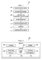
Figure 1 is an illustration of an aircraft manufacturing and service method in accordance with an advantageous embodiment; -
Figure 2 is an illustration of an aircraft in which an advantageous embodiment may be implemented; -
Figure 3 is an illustration of a block diagram of a landing gear system in accordance with an advantageous embodiment; -
Figure 4 is an illustration of a block diagram of a length reduction system in accordance with an advantageous embodiment; -
Figure 5 is an illustration of a landing gear system in accordance with an advantageous embodiment; -
Figure 6 is an illustration of a landing gear system in accordance with an advantageous embodiment; -
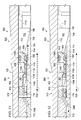
Figure 7 is an illustration of a more-detailed cross-sectional view of a shock absorber system in accordance with an advantageous embodiment; -
Figure 8 is an illustration of a more-detailed cross-sectional view of a shock absorber system in a compressed state in accordance with an advantageous embodiment; -
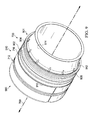
Figure 9 is an illustration of a perspective view of a portion of a shock absorber system in accordance with an advantageous embodiment; -
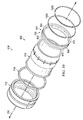
Figure 10 is an illustration of an exploded perspective view of a length reduction system in accordance with an advantageous embodiment; -
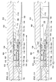
Figure 11 is an illustration of a more-detailed cross-sectional view of a portion of a shock absorber system in accordance with an advantageous embodiment; -
Figure 12 is an illustration of a more-detailed cross-sectional view of a portion of a shock absorber system in accordance with an advantageous embodiment; -
Figure 13 is an illustration of a more-detailed cross-sectional view of a portion of a shock absorber system in accordance with an advantageous embodiment; -
Figure 14 is an illustration of a more-detailed cross-sectional view of a portion of a shock absorber system in accordance with an advantageous embodiment; and -
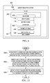
Figure 15 is an illustration of a flowchart of a process for changing a length of a landing gear system in accordance with an advantageous embodiment. - Referring more particularly to the drawings, embodiments of the disclosure may be described in the context of aircraft manufacturing and
service method 100 as shown inFigure 1 andaircraft 200 as shown inFigure 2 . Turning first toFigure 1 , an illustration of an aircraft manufacturing and service method is depicted in accordance with an advantageous embodiment. During pre-production, aircraft manufacturing andservice method 100 may include specification anddesign 102 ofaircraft 200 inFigure 2 andmaterial procurement 104. - During production, component and
subassembly manufacturing 106 andsystem integration 108 ofaircraft 200 inFigure 2 takes place. Thereafter,aircraft 200 inFigure 2 may go through certification anddelivery 110 in order to be placed inservice 112. While inservice 112 by a customer,aircraft 200 inFigure 2 is scheduled for routine maintenance andservice 114, which may include modification, reconfiguration, refurbishment, and other maintenance or service. - Each of the processes of aircraft manufacturing and
service method 100 may be performed or carried out by a system integrator, a third party, and/or an operator. In these examples, the operator may be a customer. For the purposes of this description, a system integrator may include, without limitation, any number of aircraft manufacturers and major-system subcontractors; a third party may include, without limitation, any number of venders, subcontractors, and suppliers; and an operator may be an airline, leasing company, military entity, service organization, and so on. - With reference now to
Figure 2 , an illustration of an aircraft is depicted in which an advantageous embodiment may be implemented. In this example,aircraft 200 is produced by aircraft manufacturing andservice method 100 inFigure 1 and may includeairframe 202 with a plurality ofsystems 204 andinterior 206. Examples ofsystems 204 include one or more ofpropulsion system 208,electrical system 210,hydraulic system 212,environmental system 214, andlanding gear system 216. Any number of other systems may be included. Although an aerospace example is shown, different advantageous embodiments may be applied to other industries, such as the automotive industry. - Apparatus and methods embodied herein may be employed during at least one of the stages of aircraft manufacturing and
service method 100 inFigure 1 . As used herein, the phrase "at least one of", when used with a list of items, means that different combinations of one or more of the listed items may be used and only one of each item in the list may be needed. For example, "at least one of item A, item B, and item C" may include, for example, without limitation, item A or item A and item B. This example also may include item A, item B, and item C or item B and item C. - In one illustrative example, components or subassemblies for
landing gear system 216 produced in component andsubassembly manufacturing 106 inFigure 1 may be fabricated or manufactured in a manner similar to components or subassemblies forlanding gear system 216 produced whileaircraft 200 is inservice 112 inFigure 1 . - As yet another example, a number of apparatus embodiments, method embodiments, or a combination thereof may be utilized during production stages, such as component and
subassembly manufacturing 106 andsystem integration 108 inFigure 1 . A number of apparatus embodiments, method embodiments, or a combination thereof may be utilized whileaircraft 200 is inservice 112 and/or during maintenance andservice 114 inFigure 1 . The use of a number of the different advantageous embodiments may substantially reduce the cost ofaircraft 200. - The different advantageous embodiments recognize and take into account a number of different considerations. For example, the different advantageous embodiments recognize and take into account that increasing the length of struts in a landing gear system may result in undesired constraints with respect to the design of an aircraft. The different advantageous embodiments also recognize and take into account that it may be desirable to reduce the length of struts in a landing gear system for storage in an aircraft after takeoff. For example, with longer struts, the amount of space within the aircraft may be reduced.
- Further, the different advantageous embodiments recognize and take into account that as the length of a strut increases, the hinge point of the strut with the wheel moves in an outward direction from the fuselage. In other words, the hinge point may be moved outwards away from the center of the aircraft. This type of design may result in loads on a wing that may be undesirable. Further, the different advantageous embodiments recognize and take into account that as the length of struts increases, the shape of the fuselage also may be affected.
- Thus, the different advantageous embodiments recognize and take into account that it would be desirable to shorten the length of struts for storage when the struts are moved to a retracted position during flight. The different advantageous embodiments recognize and take into account that a retractable jack may be used to extend and retract the landing gear. The different advantageous embodiments recognize and take into account that with this type of retraction, the actuator system uses an external actuator that may require additional space within the aircraft.
- The different advantageous embodiments also recognize and take into account that another solution may involve adding another structure to the strut to pull in or reduce the length of the strut. For example, a third cylinder may be placed around a shock absorber to pull the shock absorber into a retracted position. The different advantageous embodiments recognize and take into account that this type of solution increases the weight of the strut and also requires an actuator to be external to the strut to reduce the length of the strut.
- Thus, the different advantageous embodiments provide a method and apparatus for shortening the length of components in a landing gear system. One or more of the advantageous embodiments includes an apparatus that comprises a shock absorber system, a first chamber in the shock absorber system, a second chamber in the shock absorber system, and a length reduction system in the shock absorber system.
- The length reduction system is configured to allow a flow of fluid from the first chamber into the second chamber during compression of the shock absorber system. This flow occurs when the length reduction system has a first configuration. This flow also may occur when an aircraft lands or places a load on the shock absorber system. The length reduction system is configured to substantially prevent the flow of fluid from the first chamber into the second chamber when the length reduction system has a second configuration. In this second configuration, the length of the shock absorber system may be reduced in response to pressure in the first chamber when the flow is substantially prevented in the second configuration.
- The second configuration may occur when the landing gear is retracted or moved into a stowed position.
- With reference now to
Figure 3 , an illustration of a block diagram of a landing gear system is depicted in accordance with an advantageous embodiment.Landing gear system 300 is an example of one manner in whichlanding gear system 216 foraircraft 200 inFigure 2 may be implemented. As depicted,landing gear system 300 includesstrut 302, number ofwheels 304,hinge mechanism 306, andactuator system 308. -
Strut 302 is an elongate member that may have multiple components.Strut 302 has number ofwheels 304 connected to strut 302 atfirst end 310 ofstrut 302.Second end 312 ofstrut 302 is associated or moveably connected to an aircraft.Hinge mechanism 306 is configured to guidestrut 302 to rotatably move between retractedposition 314 andextended position 316.Actuator system 308 causes strut 302 to move between retractedposition 314 andextended position 316. - In these illustrative examples, strut 302 has
length 318. The different advantageous embodiments reducelength 318 ofstrut 302 whenstrut 302 is moved fromextended position 316 to retractedposition 314. In this manner, the amount of room or space needed to storestrut 302 and number ofwheels 304 may be reduced. - In these illustrative examples, strut 302 includes
shock absorber system 320.Length 318 is reduced, in these illustrative examples, by reducinglength 322 ofshock absorber system 320. As illustrated,length reduction system 324 inshock absorber system 320 is configured to reducelength 322 ofshock absorber system 320. - As depicted,
shock absorber system 320 comprisesouter cylinder 326 andinner cylinder 328. In these illustrative examples,inner cylinder 328 andouter cylinder 326 are concentric to each other. In other words,inner cylinder 328 andouter cylinder 326 share the same center through whichaxis 330 extends in these depicted examples.Inner cylinder 328 is located withinouter cylinder 326. In this manner,axis 330 extends centrally throughinner cylinder 328 andouter cylinder 326 in these examples.Inner cylinder 328 andouter cylinder 326 are configured to move relative to each other alongaxis 330. - In these depicted examples,
shock absorber system 320 also comprisesfirst bearing 332 andsecond bearing 334. In these illustrative examples, a bearing is a device that is configured to constrain relative motion between two or more components.First bearing 332 andsecond bearing 334 are configured to constrain relative motion betweenouter cylinder 326 andinner cylinder 328. -
First bearing 332 andsecond bearing 334 are located with respect toinner cylinder 328 andouter cylinder 326. In these examples,first bearing 332 andsecond bearing 334 are located betweeninner cylinder 328 andouter cylinder 326. In particular,first bearing 332 andsecond bearing 334 are located betweenouter wall 338 ofinner cylinder 328 andinner wall 340 ofouter cylinder 326. - For example, in one advantageous embodiment,
first bearing 332 is connected toouter cylinder 326 betweenouter cylinder 326 andinner cylinder 328. Further, in this embodiment,second bearing 334 is connected toinner cylinder 328 betweenouter cylinder 326 andinner cylinder 328. Of course, in other examples,first bearing 332 may be connected toouter cylinder 326 and/orinner cylinder 328, whilesecond bearing 334 may be connected toinner cylinder 328 and/orouter cylinder 326. -
First volume 346 betweenfirst bearing 332,second bearing 334,outer wall 338 ofinner cylinder 328, andinner wall 340 ofouter cylinder 326 formsfirst chamber 342.Second volume 347 withininner wall 348 ofinner cylinder 328 and withininner wall 340 ofouter cylinder 326 outside offirst volume 346 formssecond chamber 344. -
Length reduction system 324 is configured to allowflow 350 offluid 352 betweenfirst chamber 342 tosecond chamber 344 duringcompression 354 ofshock absorber system 320. In these examples,fluid 352 is hydraulic fluid that is selected for use inshock absorber system 320. - In the different illustrative examples,
compression 354 may occur when a load is applied tolanding gear system 300. For example, when an aircraft, such asaircraft 200 inFigure 2 , lands or moves on the ground, a load is applied tolanding gear system 300.Compression 354 may occur in response to this load. - Additionally, recoil 355 of
shock absorber system 320 occurs whenshock absorber system 320 is not incompression 354. In other words, when the load is reduced or no longer applied tolanding gear system 300,shock absorber system 320 may be inrecoil 355. Recoil 355 may include a normal state forshock absorber system 320 when a load is not being applied tolanding gear system 300. - In these examples,
compression 354 ofshock absorber system 320 includes a reduction inlength 356 ofouter cylinder 326 andinner cylinder 328.Length 356 is a measurement of the length of the combination ofouter cylinder 326 andinner cylinder 328 alongaxis 330. - Flow 350 of
fluid 352 betweenfirst chamber 342 andsecond chamber 344 is allowed to occur bylength reduction system 324 whenlength reduction system 324 hasfirst configuration 358. In other words,first configuration 358 forlength reduction system 324 is a configuration that allows fluid 352 to flow fromfirst chamber 342 intosecond chamber 344 and/or fromsecond chamber 344 intofirst chamber 342. - In particular,
length reduction system 324 hasfirst configuration 358 duringcompression 354. Whenlength reduction system 324 hasfirst configuration 358 duringcompression 354, flow 350 offluid 352 occurs fromsecond chamber 344 intofirst chamber 342. - Additionally,
length reduction system 324 hasfirst configuration 358 duringrecoil 355. Whenlength reduction system 324 hasfirst configuration 358 duringrecoil 355, flow 350 offluid 352 occurs fromfirst chamber 342 intosecond chamber 344. - When
length reduction system 324 hassecond configuration 360, flow 350 offluid 352 betweenfirst chamber 342 andsecond chamber 344 is substantially prevented bylength reduction system 324. In particular, flow 350 offluid 352 fromsecond chamber 344 intofirst chamber 342 is substantially prevented bylength reduction system 324. Substantially preventingflow 350 means that flow 350 offluid 352 does not occur at all or that flow 350 offluid 352 is such thatpressure 362 applied tofirst chamber 342 causeslength 322 ofshock absorber system 320 to be reduced. In particular,length 356 ofouter cylinder 326 andinner cylinder 328 is reduced. - In the illustrative examples, this reduction in
length 356 occurs in response to a sufficient amount ofpressure 362 being applied. In these illustrative examples, pump 364 inlength reduction system 324 causespressure 362 infirst chamber 342 by pumping a selected volume of suitable fluid intofirst chamber 342. - The volume of suitable fluid is selected based on the desired amount of
pressure 362 to be generated infirst chamber 342. In these depicted examples, the suitable fluid may be a hydraulic fluid, such as, for example, without limitation, a petroleum-base hydraulic fluid, a Skydrol® Type IV hydraulic fluid manufactured by Solutia Incorporated, or some other suitable type of hydraulic fluid. - Further, when
shock absorber system 320 is inrecoil 355, flow 350 offluid 352 may flow fromfirst chamber 342 intosecond chamber 344. Recoil 355 may occur in response tocompression 354 ofshock absorber system 320 in these examples. - In these illustrative examples, number of
wheels 304 is connected toinner cylinder 328. As used herein, a first component "connected to" a second component means that the first component can be connected directly or indirectly to the second component. In other words, additional components may be present between the first component and the second component. The first component is considered to be indirectly connected to the second component when one or more additional components are present between the two components. When the first component is directly connected to the second component, no additional components are present between the two components. - The illustration of
landing gear system 300 inFigure 3 is not meant to imply physical or architectural limitations to the manner in which different advantageous embodiments may be implemented. Other components in addition to and/or in place of the ones illustrated may be used. Some components may be unnecessary in some advantageous embodiments. Also, the blocks are presented to illustrate some functional components. One or more of these blocks may be combined and/or divided into different blocks when implemented in different advantageous embodiments. - For example, in the depicted examples, only strut 302 is illustrated. In other illustrative examples,
landing gear system 300 may include additional struts in addition to strut 302 in which each of the additional struts may include a length reduction system, such aslength reduction system 324 instrut 302. In yet other illustrative examples, some of the other additional struts may not include a length reduction system. - In this manner, the different advantageous embodiments provide a method and apparatus for reducing the length of a landing gear system between a retracted position and an extended position. In the different illustrative examples, the reduction in length of the landing gear system occurs without requiring components that may use additional space within the aircraft. In the different illustrative examples,
length reduction system 324 is configured to be located withinshock absorber system 320 and uses existing components withinshock absorber system 320 to reducelength 318 oflanding gear system 300. - With reference now to
Figure 4 , an illustration of a block diagram of a length reduction system is depicted in accordance with an advantageous embodiment.Length reduction system 324 is shown in more detail in this figure. In this illustrative example,length reduction system 324 takes the form ofvalve 400.Valve 400 comprisesring 402,seal carrier 404, biasingsystem 406, and number ofseals 408 in these depicted examples. -
Ring 402 is a structure that is configured to be placed betweenouter cylinder 326 andinner cylinder 328 inFigure 3 . In a similar fashion,seal carrier 404 is a structure that is also configured to be placed betweenouter cylinder 326 andinner cylinder 328. -
Ring 402 andseal carrier 404 are configured to move relative to each other alongaxis 330 inFigure 3 .Ring 402 andseal carrier 404 move relative to each other whenlength reduction system 324 changes betweenfirst configuration 358 andsecond configuration 360 inFigure 3 . - In these illustrative examples, biasing
system 406 is associated withseal carrier 404. A first component may be considered to be associated with a second component by being secured to the second component, bonded to the second component, fastened to the second component, and/or connected to the second component in some other suitable manner. The first component also may be connected to the second component using a third component. The first component may also be considered to be associated with the second component by being formed as part of and/or an extension of the second component. - In other illustrative examples, biasing
system 406 may be associated withring 402 or bothring 402 andseal carrier 404, depending on the particular implementation. In these depicted examples, biasingsystem 406 comprises at least one of a spring, a belleville washer, a split ring washer, and/or other suitable types of biasing mechanisms. - Additionally, number of
seals 408 is also associated withseal carrier 404. Number ofseals 408 is configured to substantially preventflow 350 offluid 352 betweenfirst chamber 342 andsecond chamber 344 inFigure 3 . In these illustrative examples, number ofseals 408 may take various forms. For example, number ofseals 408 may include at least one of an O-ring seal, a T-shaped seal, a cap seal, and other suitable types and/or shapes of seals. Number ofseals 408 may be comprised of different types of materials. For example, number ofseals 408 may be comprised of plastic, nylon, silicone, rubber, a thermoplastic elastomer, polyurethane, polyamide, and/or other suitable types of materials. - When
ring 402 andseal carrier 404 move towards each other,length reduction system 324 changes fromfirst configuration 358 tosecond configuration 360 inFigure 3 . Whensecond configuration 360 is reached, number ofseals 408 associated withseal carrier 404 substantially preventsflow 350 offluid 352 betweenfirst chamber 342 intosecond chamber 344. - In these illustrative examples,
ring 402 hasfirst flange 414, andseal carrier 404 hassecond flange 416.First flange 414 extends frominner side 418 ofring 402.Second flange 416 extends fromouter side 420 ofseal carrier 404. In these illustrative examples,first flange 414 andsecond flange 416 are configured to engage each other such that contact is maintained betweenring 402 andseal carrier 404 during movement ofring 402 andseal carrier 404 relative to each other. - The illustration of
length reduction system 324 inFigure 4 is not meant to imply physical or architectural limitations to the manner in which different advantageous embodiments may be implemented. Other components in addition to and/or in place of the ones illustrated may be used. Some components may be unnecessary in some advantageous embodiments. - For example, in some illustrative examples,
length reduction system 324 may not includering 402. Instead,seal carrier 404 may be configured to move freely withinfirst chamber 342 in response to flow 350 offluid 352 infirst chamber 342 to movelength reduction system 324 betweenfirst configuration 358 andsecond configuration 360. In other illustrative examples,length reduction system 324 may include other components, such as, for example, structural components. - With reference now to
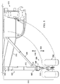
Figure 5 , an illustration of a landing gear system is depicted in accordance with an advantageous embodiment.Landing gear system 500 is an example of one implementation forlanding gear system 300 inFigure 3 . The different components shown inFigures 5-14 may be components inFigure 3 , comprised of components inFigure 3 , combined with components inFigure 3 , and/or used with components inFigure 3 . Additionally, some of the components inFigures 5-14 may be illustrative examples of how components shown in block form inFigure 3 can be implemented as physical structures. -
Landing gear system 500 comprisesstrut 502,wheels 504, andhinge system 506. An actuator system (not shown) may causehinge system 506 to movestrut 502 into different positions. - In this illustrative example,
landing gear system 500 is in deployedposition 508. When landinggear system 500 is in deployedposition 508,strut 502 is inextended position 509. As illustrated,strut 502 includesshock absorber system 510.Shock absorber system 510 hasend 511 rotatably connected toaircraft 513 havinglanding gear system 500. In particular,shock absorber system 510 is connected towing 515 ofaircraft 513. - As depicted,
shock absorber system 510 hasouter cylinder 512 andinner cylinder 514.Outer cylinder 512 andinner cylinder 514 havelength 516.Length 516 is an example oflength 356 forouter cylinder 326 andinner cylinder 328 inFigure 3 .Length 516 is a relative length forouter cylinder 512 andinner cylinder 514. In other words,length 516 changes, depending on the movement ofinner cylinder 514 relative toouter cylinder 512. - For example,
length 516 is reduced wheninner cylinder 514 moves towardsouter cylinder 512 in the direction of arrow 518.Length 516 is increased wheninner cylinder 514 moves away fromouter cylinder 512 in the direction ofarrow 520. In these illustrative examples, it is desirable to reducelength 516 whenlanding gear system 500 moves out of deployedposition 508. A reduction inlength 516 reduces the length ofshock absorber system 510, and thereby reduces the length ofstrut 502. - With reference now to
Figure 6 , an illustration of a landing gear system is depicted in accordance with an advantageous embodiment. In this illustrative example,landing gear system 500 fromFigure 5 is in stowedposition 600. As depicted,landing gear system 500 is stowed away for storage insidefuselage 602 ofaircraft 513. - With reference now to
Figure 7 , an illustration of a more-detailed cross-sectional view of a shock absorber system is depicted in accordance with an advantageous embodiment. In this illustrative example, a more-detailed view ofshock absorber system 510 fromFigure 5 is shown. In this illustrative example,outer cylinder 512 andinner cylinder 514 may move relative to each other alongaxis 700. Additionally, as depicted,outer cylinder 512 andinner cylinder 514 are concentric to each other. In particular,inner cylinder 514 is located inside ofouter cylinder 512. - In this illustrative example,
first chamber 702 andsecond chamber 704 are present withinshock absorber system 510.First chamber 702 is formed byfirst volume 706. In this depicted example,first volume 706 is defined byouter wall 708 ofinner cylinder 514,inner wall 710 ofouter cylinder 512,first bearing 712, andsecond bearing 714. - In this illustrative example,
first bearing 712 is connected toinner cylinder 514.Second bearing 714 is connected toouter cylinder 512.First bearing 712 andsecond bearing 714 are configured to constrain movement ofouter cylinder 512 relative toinner cylinder 514. -
Second chamber 704 is formed bysecond volume 707.Second volume 707 includes the volume withininner wall 713 ofinner cylinder 514 and withininner wall 710 ofouter cylinder 512 that is outside offirst volume 706. In other words,second volume 707 includes the volume withininner wall 710 ofouter cylinder 512 that is abovefirst bearing 712. - Additionally,
valve 716 is adjacent tofirst bearing 712.Valve 716 is configured to control flow offluid 718 betweenfirst chamber 702 andsecond chamber 704. In these illustrative examples,valve 716 takes the form of a recoil valve.Valve 716 is configured such that recoil fluid is allowed to flow more easily fromsecond chamber 704 intofirst chamber 702 as compared to flowing fromfirst chamber 702 back intosecond chamber 704. This configuration ofvalve 716 may be used to reduce the number of oscillations that may occur whenshock absorber system 510 is compressed and decompressed upon application of a load. This load may be, for example, an aircraft landing on a runway. - In this illustrative example,
length reduction system 720 is configured to reduce the length ofstrut 502 through the reduction inlength 516 ofouter cylinder 512 andinner cylinder 514 ofshock absorber system 510. - Additionally, in this illustrative example, fluid may be pumped into
first chamber 702 usingpump 722. Pump 722 may be used to apply pressure tolength reduction system 720 infirst chamber 702. - With reference now to
Figure 8 , an illustration of a more detailed cross-sectional view of a shock absorber system in a compressed state is depicted in accordance with an advantageous embodiment. In this illustrative example,shock absorber system 510 is shown with compression. In this example, oil flows in the direction ofarrow 800 fromsecond chamber 704 intofirst chamber 702. - With reference now to
Figure 9 , an illustration of a perspective view of a portion of a shock absorber system is depicted in accordance with an advantageous embodiment. In this illustrative example,portion 900 ofshock absorber system 510 fromFigures 5-8 is depicted withoutouter cylinder 512. In particular,portion 900 includesfirst bearing 712,valve 716, a portion ofinner cylinder 514, andlength reduction system 720. - As depicted,
length reduction system 720 takes the form ofvalve 901.Valve 901 comprisesring 902,seal carrier 904, and biasingsystem 906 aroundinner cylinder 514. -
Ring 902 andseal carrier 904 may move relative to each other alongaxis 700 throughvalve 901.Ring 902 is atfirst end 910 ofvalve 901.Seal carrier 904 is atsecond end 912 ofvalve 901. Together,ring 902 andseal carrier 904 may be referred to as a seal cartridge. - With reference now to
Figure 10 , an illustration of an exploded perspective view of a length reduction system is depicted in accordance with an advantageous embodiment. In this illustrative example,portion 900 ofshock absorber system 510 fromFigure 9 is seen in an exploded view. As depicted in this view,length reduction system 720 includesfirst seal 1000 andsecond seal 1002.Seal carrier 904 is configured to holdfirst seal 1000 andsecond seal 1002.First seal 1000 is configured to engageinner wall 710 of outer cylinder 512 (not shown).Second seal 1002 is configured to engageouter wall 708 ofinner cylinder 514. - With reference now to
Figure 11 , an illustration of a more-detailed cross-sectional view of a portion of a shock absorber system is depicted in accordance with an advantageous embodiment. In this illustrative example,shock absorber system 510 is in compression. Fluid is allowed to flow fromsecond chamber 704 inFigure 7 intofirst chamber 702 during compression ofshock absorber system 510. In particular, fluid is allowed to flow fromsecond chamber 704 throughvalve 716 intofirst chamber 702 in the direction ofarrow 1100. - Further, in this illustrative example, biasing
system 906 is configured to substantially preventsecond seal 1002 carried byseal carrier 904 from fully engagingportion 1111 ofinner cylinder 514 such that the flow of the fluid is allowed betweensecond chamber 704 andfirst chamber 702. Whensecond seal 1002 fully engagesportion 1111 ofinner cylinder 514, fluid is substantially prevented from flowing betweensecond chamber 704 andfirst chamber 702. - As depicted, the flow of fluid through
valve 716 movesvalve 716 towardsring 902.Ring 902 hasfirst flange 1102 atinner side 1104 ofring 902.Seal carrier 904 hassecond flange 1106 atouter side 1108 ofseal carrier 904.First flange 1102 andsecond flange 1106 are configured to engage whenring 902 andseal carrier 904 move towards each other. - Additionally, in this illustrative example,
shock absorber system 510 includestube 1110.Tube 1110 may be, for example, a spacer tube. In this illustrative example,tube 1110 is located inside of and connected toouter cylinder 512.Tube 1110 is located away fromlength reduction system 720 whenshock absorber system 510 is in compression in this illustrative example. In other words,tube 1110 does not engagelength reduction system 720 whenshock absorber system 510 is in compression. As depicted,length reduction system 720 is located betweenvalve 716 atfirst bearing 712 andtube 1110. - Turning now to
Figure 12 , an illustration of a more-detailed cross-sectional view of a portion of a shock absorber system is depicted in accordance with an advantageous embodiment. In this illustrative example,shock absorber system 510 is in recoil. During recoil, fluid is allowed to flow fromfirst chamber 702 intosecond chamber 704 fromFigure 7 . In particular, fluid is allowed to flow fromfirst chamber 702 throughvalve 716 intosecond chamber 704 in the direction ofarrow 1200. As depicted, the flow of fluid throughvalve 716 movesvalve 716 into contact withfirst bearing 712. - Further, as illustrated, biasing
system 906 substantially preventssecond seal 1002 from fully engagingportion 1111 ofinner cylinder 514 such that the flow of fluid is allowed betweenfirst chamber 702 andsecond chamber 704 in this example. Further,tube 1110 does not engagelength reduction system 720 whenshock absorber system 510 is in recoil. - With reference now to
Figure 13 , an illustration of a more-detailed cross-sectional view of a portion of a shock absorber system is depicted in accordance with an advantageous embodiment. In this illustrative example,inner cylinder 514 has moved relative toouter cylinder 512 in the direction ofarrow 1300.Inner cylinder 514 has moved to movestrut 502 into an extended position. - Further, as depicted,
first bearing 712 is connected toinner cylinder 514 such that movement ofinner cylinder 514 movesfirst bearing 712. - As depicted, when
inner cylinder 514 is moved in the direction ofarrow 1300,length reduction system 720 engagestube 1110. In particular,seal carrier 904 oflength reduction system 720 engagestube 1110. Whenseal carrier 904 engagestube 1110,seal carrier 904 is prevented from further moving in the direction ofarrow 1300. - With
seal carrier 904 blocked bytube 1110,first bearing 712, which is connected toinner cylinder 514, moves withinner cylinder 514 in the direction ofarrow 1300 to pushvalve 716 towardsring 902.Valve 716, which is pressing againstring 902, causesring 902 to compress biasingsystem 906 such thatring 902 moves towardseal carrier 904. Further, withvalve 716 pressed againstring 902 andring 902 pressed againstseal carrier 904,inner cylinder 514 moves in the direction ofarrow 1300 such thatportion 1111 ofinner cylinder 514 fully engagessecond seal 1002. - In this manner,
second seal 1002 fully engagesportion 1111 ofinner cylinder 514 to substantially prevent the flow of fluid betweenfirst chamber 702 andsecond chamber 704. In this manner, the flow of fluid throughfirst chamber 702 is substantially prevented whenstrut 502 is in the extended position. In particular, the flow of fluid betweenfirst chamber 702 andsecond chamber 704 inFigure 7 is substantially prevented whenstrut 502 is extended. - With reference now to
Figure 14 , an illustration of a more-detailed cross-sectional view of a portion of a shock absorber system is depicted in accordance with an advantageous embodiment. In this illustrative example, pressure may be applied tolength reduction system 720 in the direction ofarrow 1400 to movestrut 502 into a compressed state. This pressure may be applied by pumping fluid intofirst chamber 702 through, for example, pump 722 inFigure 7 . The fluid may be, for example, hydraulic fluid. - As depicted, when pressure is applied to
length reduction system 720,seal carrier 904 moves towardsring 902, andring 902 moves towardsvalve 716. In this manner, the flow of fluid betweenfirst chamber 702 andsecond chamber 704 inFigure 7 is substantially prevented whilestrut 502 is moved into the compressed state. - With reference now to
Figure 15 , an illustration of a flowchart of a process for changing a length of a landing gear system is depicted in accordance with an advantageous embodiment. The process illustrated inFigure 15 may be implemented usinglanding gear system 300 inFigure 3 . - The process begins by moving a first cylinder and a second cylinder relative to each other along an axis extending centrally through the first cylinder and the second cylinder (operation 1500). The first cylinder and the second cylinder are part of a shock absorber system in a strut. In this illustrative example, the first cylinder and the second cylinder are concentric to each other. The second cylinder is located in the first cylinder.
- The first cylinder and the second cylinder are moved such that the first cylinder and the second cylinder are in an extended position. In other words, the strut is moved into an extended position when the first cylinder and the second cylinder are moved in
operation 1500. The first cylinder may be, for example,outer cylinder 326 inFigure 3 , orouter cylinder 512 inFigures 5-8 and 11-14. The second cylinder may be, for example,inner cylinder 328 inFigure 3 , orinner cylinder 514 inFigures 5-14 . - Thereafter, the process substantially prevents a flow of fluid between a first chamber between the first cylinder and the second cylinder and a second chamber within the first cylinder in response to the first cylinder being in the extended position (operation 1502). The process then moves the first cylinder and the second cylinder relative to each other along the axis in response to a pressure applied to the first chamber (operation 1504), with the process terminating thereafter. The first cylinder and the second cylinder are moved such that a length of the first cylinder and the second cylinder is reduced. In this manner, in
operation 1504, the first cylinder and the second cylinder are moved to move the strut into a retracted position. - The flowchart and block diagrams in the different depicted embodiments illustrate the architecture, functionality, and operation of some possible implementations of apparatus and methods in different advantageous embodiments. In this regard, each block in the flowchart or block diagrams may represent a module, segment, function, and/or a portion of an operation or step. For example, one or more of the blocks may be implemented as program code, in hardware, or a combination of the program code and hardware. When implemented in hardware, the hardware may, for example, take the form of integrated circuits that are manufactured or configured to perform one or more operations in the flowcharts or block diagrams.
- In some alternative implementations, the function or functions noted in the block may occur out of the order noted in the figures. For example, in some cases, two blocks shown in succession may be executed substantially concurrently, or the blocks may sometimes be executed in the reverse order, depending upon the functionality involved. Also, other blocks may be added in addition to the illustrated blocks in a flowchart or block diagram.
- Thus, the different advantageous embodiments provide a method and apparatus for shortening or reducing the length of components in a landing gear system. One or more of the advantageous embodiments includes an apparatus that comprises a shock absorber system, a first chamber in the shock absorber system, a second chamber in the shock absorber system, and a length reduction system in the shock absorber system.
- The length reduction system is configured to allow a flow of fluid from the first chamber into the second chamber during compression of the shock absorber system. This flow occurs when the length reduction system has a first configuration. This flow also may occur when an aircraft lands or places a load on the shock absorber system. The length reduction system is configured to substantially prevent the flow of fluid from the first chamber into the second chamber when the length reduction system has a second configuration. In this second configuration, the length of the shock absorber system may be reduced in response to pressure in the first chamber when the flow is substantially prevented in the second configuration. The second configuration may occur when the landing gear is retracted or moved into a stowed position.
- In this manner, the different advantageous embodiments provide a length reduction system that reduces the length of the strut for a landing gear system for an aircraft without increasing the weight and/or complexity of the landing gear system in an undesired manner.
- In one exemplary embodiment, an apparatus is disclosed including a shock absorber system; a first chamber in the shock absorber system; a second chamber in the shock absorber system; and a length reduction system in the shock absorber system in which the length reduction system is configured to allow a flow of a fluid between the first chamber and the second chamber when the length reduction system has a first configuration and configured to substantially prevent the flow of the fluid between the first chamber and the second chamber when the length reduction system has a second configuration such that a length of the shock absorber system reduces in response to a pressure in the first chamber when the flow of the fluid is substantially prevented.
- In one variant, the shock absorber system includes an outer cylinder; and an inner cylinder located within the outer cylinder, wherein the inner cylinder and the outer cylinder are configured to move relative to each other along an axis extending centrally through the inner cylinder and the outer cylinder. In yet another variant, further including a number of wheels, wherein the number of wheels is connected to the inner cylinder. In one variant, the first chamber is located between the inner cylinder and the outer cylinder and the second chamber is located inside of the inner cylinder and the outer cylinder.
- In yet another variant, the first chamber is located between a first bearing connected to the outer cylinder and a second bearing connected to the inner cylinder. In yet another alternative, the length reduction system is located between a valve located at the first bearing and a spacer tube located inside the outer cylinder. In yet another alternative, the length reduction system includes a ring located between the outer cylinder and the inner cylinder; and a seal carrier moveable relative to the ring along the axis, wherein movement of the outer cylinder and the inner cylinder into an extended position causes the ring and the seal carrier to move relative to each other into the second configuration of the length reduction system.
- In yet another variant, the length of the shock absorber system is a first length and wherein application of the pressure within the first chamber causes the inner cylinder to move relative to the outer cylinder such that a second length of the inner cylinder and the outer cylinder is reduced such that the first length is reduced.
- In another variant, the length reduction system further includes a biasing system configured to substantially prevent a number of seals carried by the seal carrier from engaging a portion of the inner cylinder such that the flow of the fluid is allowed between the first chamber and the second chamber, wherein the number of seals carried by the seal carrier engages the portion of the inner cylinder such that the flow of the fluid between the first chamber and the second chamber is substantially prevented when a spacer tube engages the seal carrier. In one variant, the biasing system includes at least one of a spring, a belleville washer, and a split ring washer. In yet another variant, the seal carrier is configured to hold a first seal and a second seal, wherein the first seal is configured to engage an inner wall of the outer cylinder and the second seal is configured to engage an outer wall of the inner cylinder.
- In another variant, the ring has a first flange extending from an inner side of the ring in which the first flange is configured to engage a second flange extending from an outer side of the seal carrier
such that contact is maintained between the ring and the seal carrier. - In another variant, the flow of the fluid occurs from the first chamber to the second chamber when the length reduction system has the first configuration during compression of the shock absorber system and from the second chamber to the first chamber during recoil of the shock absorber system.
- In one variant, an actuator system may be configured to move the shock absorber system and the number of wheels between a retracted position and an extended position.
- In one exemplary embodiment, an apparatus is disclosed that includes a ring configured to be placed between an outer cylinder and an inner cylinder; a seal carrier configured to be placed between the outer cylinder and the inner cylinder, wherein the seal carrier and the ring are configured to move relative to each other between a first configuration and a second configuration along an axis extending centrally through the outer cylinder and the inner cylinder; and a number of seals associated with the seal carrier, wherein the number of seals is configured to engage an inner wall of the outer cylinder and an outer wall of the inner cylinder. In one variant, a biasing system may be included. In yet another variant, a first flange is extending from an inner side of the ring; and a second flange is extending from an outer side of the seal carrier, wherein the first flange is configured to engage the second flange such that contact is maintained between the ring and the seal carrier.
- The description of the different advantageous embodiments has been presented for purposes of illustration and description and is not intended to be exhaustive or limited to the embodiments in the form disclosed. Many modifications and variations will be apparent to those of ordinary skill in the art. Further, different advantageous embodiments may provide different advantages as compared to other advantageous embodiments. The embodiment or embodiments selected are chosen and described in order to best explain the principles of the embodiments, the practical application, and to enable others of ordinary skill in the art to understand the disclosure for various embodiments with various modifications as are suited to the particular use contemplated.
Claims (15)
- An apparatus comprising:a shock absorber system(320);a first chamber(342) in the shock absorber system(320);a second chamber(344) in the shock absorber system(320); anda length reduction system(324) in the shock absorber system(320) in which the length reduction system(324) is configured to allow a flow of a fluid between the first chamber(342) and the second chamber (344) when the length reduction system(324) has a first configuration and configured to substantially prevent the flow of the fluid between the first chamber(342) and the second chamber(344) when the length reduction system (324) has a second configuration such that a length of the shock absorber system(324) reduces in response to a pressure in the first chamber(342) when the flow of the fluid is substantially prevented.
- The apparatus of claim 1 wherein the shock absorber system (320)comprises:an outer cylinder(326); andan inner cylinder(328)located within the outer cylinder(326), wherein the inner cylinder(328) and the outer cylinder(326) are configured to move relative to each other along an axis extending centrally through the inner cylinder(328) and the outer cylinder.
- The apparatus of any of the claims 1 and 2 further comprising:a number of wheels(304), wherein the number of wheels (304) is connected to the inner cylinder (328).
- The apparatus of the claim 2 wherein the first chamber(342) is located between the inner cylinder(328)and the outer cylinder(326) and the second chamber(344) is located inside of the inner cylinder(328)and the outer cylinder(326).
- The apparatus of any of the claims 2 and 4 wherein the length reduction system(324)comprises:a ring (402) located between the outer cylinder(326) and the inner cylinder(328); anda seal carrier(404)moveable relative to the ring (402) along the axis, wherein movement of the outer cylinder(326)and the inner cylinder (328)into an extended position causes the ring (402)and the seal carrier(404) to move relative to each other into the second configuration of the length reduction system (324).
- The apparatus of any of the claims 2, 4, and 5 wherein the length of the shock absorber system (320) is a first length and wherein application of the pressure within the first chamber (342) causes the inner cylinder (328) to move relative to the outer cylinder (326) such that a second length of the inner cylinder (328) and the outer cylinder (326) is reduced such that the first length is reduced.
- The apparatus of any of the claims 2-6 wherein the length reduction system (324)further comprises:a biasing system(406)configured to substantially prevent a number of seals(408)carried by the seal carrier (404)from engaging a portion of the inner cylinder (328)such that the flow of the fluid is allowed between the first chamber(342)and the second chamber(344), wherein the number of seals(408)carried by the seal carrier (404)engages the portion of the inner cylinder (328)such that the flow of the fluid between the first chamber(342) and the second chamber(344)is substantially prevented when a spacer tube engages the seal carrier(404).
- The apparatus of any of the preceding claims wherein the flow of the fluid occurs from the first chamber (342) to the second chamber (344) when the length reduction system (324) has the first configuration during compression of the shock absorber system (320) and from the second chamber (344) to the first chamber (342) during recoil of the shock absorber system (320).
- A method for changing a length of a landing gear system(300), the method comprising:moving a first cylinder(324)and a second cylinder (328)relative to each other along an axis extending centrally through the first cylinder(324)and the second cylinder (328)such that the first cylinder(324) and the second cylinder(328)are in an extended position;responsive to the first cylinder(324) and the second cylinder (328) being in the extended position, substantially preventing a flow of a fluid between a first chamber(342) formed between the first cylinder (324)and the second cylinder(328)and a second chamber (344) within the first cylinder(324)and the second cylinder(328); andresponsive to a pressure applied to the first chamber(342), moving the first cylinder(326) and the second cylinder(328)relative to the each other along the axis such that a length of the first cylinder(326) and the second cylinder(328)is reduced.
- The method of claim 9 wherein the step of substantially preventing the flow of the fluid between the first chamber(342)formed between the first cylinder (326)and the second cylinder(328)and the second chamber(344)within the first cylinder(326) and the second cylinder(328)is performed using a length reduction system (324)and comprises:responsive to movement of the first cylinder (342) and the second cylinder(328) into the extended position, moving a seal carrier(404) in the length reduction system (324)relative to a ring(402)in the length reduction system(324) to substantially prevent the flow of the fluid between the first chamber(342) and the second chamber(344), wherein the ring(402)and the seal carrier(404)are located between the first cylinder (326)and the second cylinder(328).
- The method of any of the claims 9 and 10 wherein the first cylinder (326)and the second cylinder(328)are part of a shock absorber system (320) and further comprising:moving the shock absorber system (320) and a number of wheels (304) connected to the shock absorber system (320) between a retracted position and the extended position.
- The method of claim 10 further comprising:extending a first flange (414) from an inner side of the ring (402); andextending a second flange (416) from an outer side of the seal carrier (404), wherein the first flange (414) is configured to engage the second flange (416) such that contact is maintained between the ring (402) and the seal carrier (404).
- The method of claim 11 further comprising:moving by an actuator system (308) the shock absorber system (320) and the number of wheels (304) between a retracted position and an extended position.
- The method of any of the claims 11-13 further comprising:locating the first chamber (344) between a first bearing (332) connected to the outer cylinder (326) and a second bearing (334) connected to the inner cylinder (328).
- The method of claim 11, further comprising:locating the length reduction system (324) between a valve (400) located at the first bearing (332) and a spacer tube (1110) located inside the outer cylinder (326).
Applications Claiming Priority (1)
| Application Number | Priority Date | Filing Date | Title |
|---|---|---|---|
| US13/078,075 US8998133B2 (en) | 2011-04-01 | 2011-04-01 | Landing gear system |
Publications (3)
| Publication Number | Publication Date |
|---|---|
| EP2505499A2 true EP2505499A2 (en) | 2012-10-03 |
| EP2505499A3 EP2505499A3 (en) | 2014-04-02 |
| EP2505499B1 EP2505499B1 (en) | 2015-12-09 |
Family
ID=45936805
Family Applications (1)
| Application Number | Title | Priority Date | Filing Date |
|---|---|---|---|
| EP12159953.4A Active EP2505499B1 (en) | 2011-04-01 | 2012-03-16 | Landing gear system |
Country Status (5)
| Country | Link |
|---|---|
| US (1) | US8998133B2 (en) |
| EP (1) | EP2505499B1 (en) |
| JP (1) | JP6039913B2 (en) |
| CN (1) | CN102730188B (en) |
| ES (1) | ES2556963T3 (en) |
Cited By (1)
| Publication number | Priority date | Publication date | Assignee | Title |
|---|---|---|---|---|
| EP2860102A1 (en) * | 2013-10-11 | 2015-04-15 | Goodrich Corporation | Shrink strut landing gear system |
Families Citing this family (18)
| Publication number | Priority date | Publication date | Assignee | Title |
|---|---|---|---|---|
| US9481452B2 (en) | 2010-11-22 | 2016-11-01 | The Boeing Company | Hydraulic actuator for semi levered landing gear |
| US8939400B2 (en) | 2011-02-21 | 2015-01-27 | The Boeing Company | Air-ground detection system for semi-levered landing gear |
| EP3263449B1 (en) * | 2016-07-01 | 2018-08-29 | Safran Landing Systems UK Limited | Aircraft landing gear |
| US10486802B2 (en) | 2016-09-19 | 2019-11-26 | Goodrich Corporation | Landing gear arrangement with passive shock strut shrink actuator |
| US10562614B2 (en) | 2016-09-21 | 2020-02-18 | The Boeing Company | Aircraft landing gear, aircraft, and related methods |
| US10384767B2 (en) | 2017-01-25 | 2019-08-20 | The Boeing Company | Single axle, semi-levered landing gear with shortening mechanism |
| US10597146B2 (en) | 2017-02-28 | 2020-03-24 | The Boeing Company | Aircraft landing gear having a lever assembly, aircraft including the same, and related methods |
| US10669017B2 (en) | 2017-02-28 | 2020-06-02 | The Boeing Company | Aircraft landing gear, aircraft, and related methods |
| US10766608B2 (en) | 2017-02-28 | 2020-09-08 | The Boeing Company | Aircraft landing gear having a retract actuator, aircraft including the same, and related methods |
| US10625849B2 (en) | 2017-04-11 | 2020-04-21 | The Boeing Company | Levered landing gear with inner shock strut |
| US10800516B2 (en) | 2017-06-02 | 2020-10-13 | The Boeing Company | Semi-levered shrink landing gear |
| US10591013B2 (en) | 2017-06-14 | 2020-03-17 | Safran Landing Systems Canada Inc. | Lubrication mechanism design for aircraft landing gear bearings |
| US11161599B2 (en) | 2018-01-26 | 2021-11-02 | The Boeing Company | Landing gear strut assembly and method therefor |
| US11008091B2 (en) | 2018-05-03 | 2021-05-18 | The Boeing Company | Body mounted shrinking landing gear |
| US10981646B2 (en) | 2018-07-30 | 2021-04-20 | The Boeing Company | Landing gear shrink link mechanism |
| US11433994B2 (en) | 2019-07-17 | 2022-09-06 | The Boeing Company | Mechanical link with preload verification |
| US10793262B1 (en) | 2019-07-17 | 2020-10-06 | The Boeing Company | Mechanical link with preload verification |
| US10583919B1 (en) | 2019-07-17 | 2020-03-10 | The Boeing Company | Mechanical link with preload verification |
Family Cites Families (82)
| Publication number | Priority date | Publication date | Assignee | Title |
|---|---|---|---|---|
| GB594541A (en) | 1944-10-23 | 1947-11-13 | Miles Aircraft Ltd | Improvements in aircraft landing gear |
| US2193736A (en) | 1936-11-14 | 1940-03-12 | Onions John Henry | Fluid pressure motor |
| US2783744A (en) | 1955-09-21 | 1957-03-05 | Hydraulic Unit Specialities Co | Multistage hydraulic cylinder |
| US2932281A (en) | 1958-06-25 | 1960-04-12 | North American Aviation Inc | Double-acting actuator means |
| US3082980A (en) | 1958-09-03 | 1963-03-26 | Sarl Rech S Etudes Production | Multi-purpose landing gear with wheels in tandem |
| US3083937A (en) | 1959-02-05 | 1963-04-02 | English Electric Co Ltd | Aeroplane undercarriages |
| US3237726A (en) * | 1962-09-07 | 1966-03-01 | Bendix Corp | Shock absorber lock |
| US3188922A (en) * | 1962-10-12 | 1965-06-15 | Wagner Electric Corp | Friction device operating mechanism |
| GB1024455A (en) | 1963-04-09 | 1966-03-30 | Electro Hydraulics Ltd | Retractable undercarriages for aircraft |
| GB1006522A (en) | 1963-10-08 | 1965-10-06 | Electro Hydraulics Ltd | Retractable undercarriages for aircraft |
| US3335642A (en) | 1965-01-08 | 1967-08-15 | Borje O Rosaen | Cylinder construction |
| US3290038A (en) * | 1965-01-14 | 1966-12-06 | Bendix Corp | Extensible shock absorber |
| US3426651A (en) * | 1966-07-26 | 1969-02-11 | Pneumo Dynamics Corp | Air-oil suspension |
| US3533613A (en) * | 1967-11-02 | 1970-10-13 | Lockheed Aircraft Corp | Axially retractable landing gear |
| US3578303A (en) | 1969-04-02 | 1971-05-11 | Abex Ind Canada Ltd | Oleo-pneumatic shock absorbers |
| US3568705A (en) | 1969-08-19 | 1971-03-09 | Bendix Corp | Hydraulic system circuit breaker |
| US3724832A (en) | 1971-03-09 | 1973-04-03 | Menasco Mfg Co | Oleo-pneumatic shock absorber |
| US3869861A (en) | 1973-10-15 | 1975-03-11 | Hesston Corp | Combination hydraulic cylinder and accumulator |
| US3845919A (en) | 1974-01-07 | 1974-11-05 | Boeing Co | Landing gear truck pitch damping |
| US4007894A (en) | 1975-12-04 | 1977-02-15 | The Boeing Company | Method and apparatus for minimizing axial friction forces in a cylinder-piston shock absorber |
| US4061295A (en) | 1975-12-22 | 1977-12-06 | The Boeing Company | Shock absorbing method and apparatus |
| US4075929A (en) | 1976-01-28 | 1978-02-28 | The United States Of America As Represented By The Secretary Of The Air Force | Three stage thrusting device |
| FR2370196A2 (en) | 1976-02-04 | 1978-06-02 | Messier Hispano Sa | IMPROVEMENTS TO SHOCK ABSORBERS-CYLINDERS |
| FR2448662A1 (en) * | 1979-02-06 | 1980-09-05 | Messier Hispano Bugatti Sa | IMPROVEMENTS ON SHOCK ABSORBERS AND CYLINDER SHOCK ABSORBERS, PARTICULARLY FOR AERODYNE LANDING GEARS |
| US4291850A (en) * | 1979-03-19 | 1981-09-29 | Lockheed Corporation | Contractable shock absorber strut |
| US4359199A (en) | 1979-12-05 | 1982-11-16 | The United States Of America As Represented By The Secretary Of The Air Force | Soft landing gear |
| FR2493444A1 (en) * | 1980-10-30 | 1982-05-07 | Messier Hispano Sa | SHOCK-CYLINDER |
| US4381857A (en) * | 1980-12-08 | 1983-05-03 | Lockheed Corporation | Programmed oleo-pneumatic shock absorber |
| FR2503662A1 (en) | 1981-04-08 | 1982-10-15 | Messier Hispano Sa | LANDING TRAIN AS TANDEM |
| DE3114525A1 (en) | 1981-04-10 | 1982-11-04 | Gewerkschaft Eisenhütte Westfalia, 4670 Lünen | HYDRAULIC PRESS CYLINDER FOR PIPE PRESSING AND THE LIKE |
| GB2101542A (en) | 1981-06-13 | 1983-01-19 | British Aerospace | Aircraft undercarriage unit |
| US4749452A (en) | 1981-12-30 | 1988-06-07 | Oronzio De Nora Impianti Elettrochimici S.P.A. | Multi-layer electrode membrane-assembly and electrolysis process using same |
| FR2598676B1 (en) | 1986-05-13 | 1988-07-29 | Messier Hispano Sa | AIRCRAFT LANDER WITH TIPPING BEAM AND REDUCED SIZE |
| US4770372A (en) | 1986-09-30 | 1988-09-13 | The Boeing Company | Two-stage aircraft landing gear |
| US4869444A (en) | 1986-09-30 | 1989-09-26 | The Boeing Company | Adjustable two-stage aircraft landing gear system |
| US4746086A (en) | 1987-03-09 | 1988-05-24 | Pneumo Abex Corporation | Nose landing gear jump strut assembly |
| FR2616410B1 (en) | 1987-06-09 | 1992-08-21 | Messier Hispano Sa | TIPPING BEAM LANDING DEVICE |
| GB8803134D0 (en) | 1988-02-11 | 1988-03-09 | British Aerospace | Aircraft undercarriage unit |
| IL86374A0 (en) | 1988-05-13 | 1988-11-30 | Israel Aircraft Ind Ltd | Aircraft landing gear shortening apparatus |
| FR2647170B1 (en) | 1989-05-18 | 1991-08-30 | Aerospatiale | DEVICE FOR REDUCING THE FLEXIBILITY OF AN OLEO-PNEUMATIC LANDING SHOCK ABSORBER, AND DAMPER AND LANDING COMPRISING SAME |
| US5086995A (en) | 1990-04-09 | 1992-02-11 | The Boeing Company | Aft cantilevered wing landing gear for heavy airplane with aft center of gravity |
| EP0461981A3 (en) * | 1990-06-13 | 1993-08-04 | Messier Bugatti | Spring-damper unit with variable stroke for a vehicle |
| FR2663289B1 (en) * | 1990-06-18 | 1992-09-18 | Messier Bugatti | AIRPLANE SHOCK ABSORBER. |
| US5140894A (en) | 1991-01-16 | 1992-08-25 | Axelson, Inc. | Gas spring actuator |
| US5148896A (en) | 1991-07-01 | 1992-09-22 | The Boeing Company | High pressure hydropneumatic shock absorber |
| FR2681308B1 (en) * | 1991-09-17 | 1993-12-17 | Messier Bugatti | LIFTABLE ANTI-CRASH SHOCK ABSORBER. |
| US5396973A (en) | 1991-11-15 | 1995-03-14 | Lord Corporation | Variable shock absorber with integrated controller, actuator and sensors |
| FR2686857B1 (en) * | 1992-02-04 | 1994-04-01 | Messier Bugatti | AIRCRAFT LANDING LEG SHOCK ABSORBER. |
| FR2688467B1 (en) | 1992-03-11 | 1994-05-13 | Messier Bugatti | LIFT LEVER WITH LEG SHORTENING. |
| GB9223714D0 (en) | 1992-11-12 | 1992-12-23 | British Aerospace | Auxiliary control of aircraft landing gear movement |
| FR2699886B1 (en) | 1992-12-28 | 1995-03-24 | Messier Bugatti | Liftable undercarriage, especially for large aircraft. |
| FR2702446B1 (en) | 1993-03-08 | 1995-06-09 | Messier Bugatti | LIFTABLE LANDING GEAR FOR LARGE AIRCRAFT. |
| US5390586A (en) | 1994-03-28 | 1995-02-21 | Jones; Peter D. | Self-bleeding hydraulic cylinder |
| US5826833A (en) | 1995-05-15 | 1998-10-27 | The Boeing Company | System for providing an air/ground signal to aircraft flight control systems |
| US5908174A (en) * | 1996-10-31 | 1999-06-01 | Coltec Industries Inc. | Automatic shrink shock strut for an aircraft landing gear |
| US6128951A (en) | 1997-04-15 | 2000-10-10 | Trinity Airweighs, L.L.C. | Aircraft weight and center of gravity indicator |
| US6182925B1 (en) | 1999-03-30 | 2001-02-06 | The Boeing Company | Semi-levered landing gear and auxiliary strut therefor |
| US6575405B2 (en) | 1999-03-30 | 2003-06-10 | The Boeing Company | Control system and method for a semi-levered landing gear for an aircraft |
| FR2849830B1 (en) | 2003-01-10 | 2005-12-16 | Messier Dowty Sa | LANDING TRAIN LEG SHOCK, AND INDEPENDENT LEGS LANDING TRAIN EQUIPPED WITH SUCH SHOCK ABSORBER |
| FR2856976B1 (en) | 2003-07-02 | 2005-10-21 | Messier Dowty Sa | LANDING TRAIN WITH INDEPENDENT LEGS OF THE VERTICAL LIFTING TYPE |
| EP2277774B1 (en) | 2004-06-18 | 2016-03-09 | Goodrich Corporation | Retractable articulated landing gear |
| WO2007005040A2 (en) * | 2004-09-17 | 2007-01-11 | Aurora Flight Sciences | Adaptive landing gear |
| WO2006094145A1 (en) | 2005-03-02 | 2006-09-08 | Goodrich Corporation | Landing gear with articulated length extension mechanism |
| US7193530B2 (en) | 2005-03-29 | 2007-03-20 | Nance C Kirk | Aircraft landing gear automated inspection and life limitation escalation system and method |
| DE102005027385B4 (en) | 2005-06-14 | 2011-08-18 | Airbus Operations GmbH, 21129 | Method and device for supporting the star rotation of an aircraft |
| GB0515359D0 (en) | 2005-07-26 | 2005-08-31 | Airbus Uk Ltd | Landing gear |
| GB2428650B (en) | 2005-08-04 | 2011-01-12 | Messier Dowty Ltd | Landing gear |
| US20070068754A1 (en) | 2005-09-26 | 2007-03-29 | Furgala George W | Gas-biased hydraulic cylinder |
| FR2895483B1 (en) | 2005-12-23 | 2008-10-24 | Messier Bugatti Sa | TELESCOPIC ACTUATOR WITH MAIN ROD AND AUXILIARY ROD, AND METHOD USING THE SAME |
| JP4809902B2 (en) * | 2006-01-13 | 2011-11-09 | グッドリッチ コーポレイション | Aircraft shock absorber strut with improved cylinder and bearing |
| US20090210105A1 (en) | 2006-05-15 | 2009-08-20 | Lusby Brock D | Air-ground detection system and method |
| FR2917371B1 (en) * | 2007-06-15 | 2009-11-20 | Messier Dowty Sa | AIRCRAFT DRIVER SHOCK ABSORBER |
| GB2453554B (en) * | 2007-10-09 | 2012-03-14 | Messier Dowty Ltd | Load detection in an aircraft landing gear |
| US8403115B2 (en) | 2008-01-11 | 2013-03-26 | Penske Racing Shocks | Dual rate gas spring shock absorber |
| FR2935680B1 (en) | 2008-09-08 | 2011-05-20 | Airbus | REAR LANDING TRAIN AT VARIABLE HEIGHT |
| US8556209B2 (en) * | 2008-10-22 | 2013-10-15 | Goodrich Corporation | Electric-powered transfer cylinder for landing gear system |
| US8070095B2 (en) * | 2008-10-22 | 2011-12-06 | Goodrich Corporation | Shrinking shock strut system for retractable landing gear |
| US8087610B2 (en) * | 2009-01-22 | 2012-01-03 | Goodrich Corporation | Aircraft shock strut having fixed upper bearing |
| EP2383604B1 (en) | 2009-01-27 | 2016-02-24 | Sharp Kabushiki Kaisha | Liquid crystal display apparatus |
| US8448900B2 (en) | 2010-03-24 | 2013-05-28 | The Boeing Company | Semi-levered landing gear and associated method |
| US9481452B2 (en) | 2010-11-22 | 2016-11-01 | The Boeing Company | Hydraulic actuator for semi levered landing gear |
| US8939400B2 (en) | 2011-02-21 | 2015-01-27 | The Boeing Company | Air-ground detection system for semi-levered landing gear |
-
2011
- 2011-04-01 US US13/078,075 patent/US8998133B2/en active Active
-
2012
- 2012-02-28 CN CN201210048066.9A patent/CN102730188B/en active Active
- 2012-03-16 ES ES12159953.4T patent/ES2556963T3/en active Active
- 2012-03-16 EP EP12159953.4A patent/EP2505499B1/en active Active
- 2012-03-30 JP JP2012081145A patent/JP6039913B2/en active Active
Non-Patent Citations (1)
| Title |
|---|
| None |
Cited By (2)
| Publication number | Priority date | Publication date | Assignee | Title |
|---|---|---|---|---|
| EP2860102A1 (en) * | 2013-10-11 | 2015-04-15 | Goodrich Corporation | Shrink strut landing gear system |
| US9321525B2 (en) | 2013-10-11 | 2016-04-26 | Goodrich Corporation | Shrink strut landing gear system, method, and apparatus |
Also Published As
| Publication number | Publication date |
|---|---|
| EP2505499B1 (en) | 2015-12-09 |
| US20120247892A1 (en) | 2012-10-04 |
| US8998133B2 (en) | 2015-04-07 |
| JP2012218730A (en) | 2012-11-12 |
| JP6039913B2 (en) | 2016-12-07 |
| ES2556963T3 (en) | 2016-01-21 |
| CN102730188B (en) | 2016-03-16 |
| CN102730188A (en) | 2012-10-17 |
| EP2505499A3 (en) | 2014-04-02 |
Similar Documents
| Publication | Publication Date | Title |
|---|---|---|
| US8998133B2 (en) | Landing gear system | |
| US9321525B2 (en) | Shrink strut landing gear system, method, and apparatus | |
| US9764827B2 (en) | Hydraulic strut assembly for semi-levered landing gear | |
| EP3366579B1 (en) | Aircraft landing gear, aircraft, and related methods | |
| US9771147B2 (en) | Shrink strut landing gear system, method, and apparatus | |
| CN109969386B (en) | Aircraft assembly | |
| US11407499B2 (en) | Aircraft landing gear having a lever assembly, aircraft including the same, and related methods | |
| US11186360B2 (en) | Aircraft landing gear, aircraft, and related methods | |
| US20150129381A1 (en) | Cam-operated bi-directional shock absorber damper | |
| EP2664538B1 (en) | Hydraulic strut assembly for semi-levered landing gear | |
| US8683795B1 (en) | Control valve for a hydraulic refueling boom system | |
| US20250074581A1 (en) | Retract actuator assemblies, landing gear assemblies and methods for kneeling landing gear assembly of aircraft | |
| US20180079496A1 (en) | Landing gear arrangement with passive shock strut shrink actuator |
Legal Events
| Date | Code | Title | Description |
|---|---|---|---|
| PUAI | Public reference made under article 153(3) epc to a published international application that has entered the european phase |
Free format text: ORIGINAL CODE: 0009012 |
|
| 17P | Request for examination filed |
Effective date: 20120316 |
|
| AK | Designated contracting states |
Kind code of ref document: A2 Designated state(s): AL AT BE BG CH CY CZ DE DK EE ES FI FR GB GR HR HU IE IS IT LI LT LU LV MC MK MT NL NO PL PT RO RS SE SI SK SM TR |
|
| AX | Request for extension of the european patent |
Extension state: BA ME |
|
| PUAL | Search report despatched |
Free format text: ORIGINAL CODE: 0009013 |
|
| AK | Designated contracting states |
Kind code of ref document: A3 Designated state(s): AL AT BE BG CH CY CZ DE DK EE ES FI FR GB GR HR HU IE IS IT LI LT LU LV MC MK MT NL NO PL PT RO RS SE SI SK SM TR |
|
| AX | Request for extension of the european patent |
Extension state: BA ME |
|
| RIC1 | Information provided on ipc code assigned before grant |
Ipc: B64C 25/60 20060101AFI20140226BHEP Ipc: B64C 25/10 20060101ALI20140226BHEP |
|
| GRAP | Despatch of communication of intention to grant a patent |
Free format text: ORIGINAL CODE: EPIDOSNIGR1 |
|
| RIC1 | Information provided on ipc code assigned before grant |
Ipc: B64C 25/60 20060101AFI20150129BHEP Ipc: B64C 25/00 20060101ALI20150129BHEP Ipc: B64C 25/10 20060101ALI20150129BHEP Ipc: B64C 25/22 20060101ALI20150129BHEP |
|
| INTG | Intention to grant announced |
Effective date: 20150209 |
|
| GRAP | Despatch of communication of intention to grant a patent |
Free format text: ORIGINAL CODE: EPIDOSNIGR1 |
|
| INTG | Intention to grant announced |
Effective date: 20150617 |
|
| GRAS | Grant fee paid |
Free format text: ORIGINAL CODE: EPIDOSNIGR3 |
|
| GRAA | (expected) grant |
Free format text: ORIGINAL CODE: 0009210 |
|
| AK | Designated contracting states |
Kind code of ref document: B1 Designated state(s): AL AT BE BG CH CY CZ DE DK EE ES FI FR GB GR HR HU IE IS IT LI LT LU LV MC MK MT NL NO PL PT RO RS SE SI SK SM TR |
|
| REG | Reference to a national code |
Ref country code: GB Ref legal event code: FG4D |
|
| REG | Reference to a national code |
Ref country code: AT Ref legal event code: REF Ref document number: 764451 Country of ref document: AT Kind code of ref document: T Effective date: 20151215 Ref country code: CH Ref legal event code: EP |
|
| REG | Reference to a national code |
Ref country code: IE Ref legal event code: FG4D |
|
| REG | Reference to a national code |
Ref country code: ES Ref legal event code: FG2A Ref document number: 2556963 Country of ref document: ES Kind code of ref document: T3 Effective date: 20160121 Ref country code: DE Ref legal event code: R096 Ref document number: 602012012821 Country of ref document: DE |
|
| REG | Reference to a national code |
Ref country code: FR Ref legal event code: PLFP Year of fee payment: 5 |
|
| REG | Reference to a national code |
Ref country code: LT Ref legal event code: MG4D |
|
| REG | Reference to a national code |
Ref country code: NL Ref legal event code: MP Effective date: 20151209 |
|
| PG25 | Lapsed in a contracting state [announced via postgrant information from national office to epo] |
Ref country code: LT Free format text: LAPSE BECAUSE OF FAILURE TO SUBMIT A TRANSLATION OF THE DESCRIPTION OR TO PAY THE FEE WITHIN THE PRESCRIBED TIME-LIMIT Effective date: 20151209 Ref country code: NO Free format text: LAPSE BECAUSE OF FAILURE TO SUBMIT A TRANSLATION OF THE DESCRIPTION OR TO PAY THE FEE WITHIN THE PRESCRIBED TIME-LIMIT Effective date: 20160309 |
|
| REG | Reference to a national code |
Ref country code: AT Ref legal event code: MK05 Ref document number: 764451 Country of ref document: AT Kind code of ref document: T Effective date: 20151209 |
|
| PG25 | Lapsed in a contracting state [announced via postgrant information from national office to epo] |
Ref country code: GR Free format text: LAPSE BECAUSE OF FAILURE TO SUBMIT A TRANSLATION OF THE DESCRIPTION OR TO PAY THE FEE WITHIN THE PRESCRIBED TIME-LIMIT Effective date: 20160310 Ref country code: RS Free format text: LAPSE BECAUSE OF FAILURE TO SUBMIT A TRANSLATION OF THE DESCRIPTION OR TO PAY THE FEE WITHIN THE PRESCRIBED TIME-LIMIT Effective date: 20151209 Ref country code: LV Free format text: LAPSE BECAUSE OF FAILURE TO SUBMIT A TRANSLATION OF THE DESCRIPTION OR TO PAY THE FEE WITHIN THE PRESCRIBED TIME-LIMIT Effective date: 20151209 Ref country code: FI Free format text: LAPSE BECAUSE OF FAILURE TO SUBMIT A TRANSLATION OF THE DESCRIPTION OR TO PAY THE FEE WITHIN THE PRESCRIBED TIME-LIMIT Effective date: 20151209 Ref country code: SE Free format text: LAPSE BECAUSE OF FAILURE TO SUBMIT A TRANSLATION OF THE DESCRIPTION OR TO PAY THE FEE WITHIN THE PRESCRIBED TIME-LIMIT Effective date: 20151209 Ref country code: NL Free format text: LAPSE BECAUSE OF FAILURE TO SUBMIT A TRANSLATION OF THE DESCRIPTION OR TO PAY THE FEE WITHIN THE PRESCRIBED TIME-LIMIT Effective date: 20151209 |
|
| PG25 | Lapsed in a contracting state [announced via postgrant information from national office to epo] |
Ref country code: IS Free format text: LAPSE BECAUSE OF FAILURE TO SUBMIT A TRANSLATION OF THE DESCRIPTION OR TO PAY THE FEE WITHIN THE PRESCRIBED TIME-LIMIT Effective date: 20151209 |
|
| PG25 | Lapsed in a contracting state [announced via postgrant information from national office to epo] |
Ref country code: CZ Free format text: LAPSE BECAUSE OF FAILURE TO SUBMIT A TRANSLATION OF THE DESCRIPTION OR TO PAY THE FEE WITHIN THE PRESCRIBED TIME-LIMIT Effective date: 20151209 |
|
| PG25 | Lapsed in a contracting state [announced via postgrant information from national office to epo] |
Ref country code: PT Free format text: LAPSE BECAUSE OF FAILURE TO SUBMIT A TRANSLATION OF THE DESCRIPTION OR TO PAY THE FEE WITHIN THE PRESCRIBED TIME-LIMIT Effective date: 20160411 Ref country code: EE Free format text: LAPSE BECAUSE OF FAILURE TO SUBMIT A TRANSLATION OF THE DESCRIPTION OR TO PAY THE FEE WITHIN THE PRESCRIBED TIME-LIMIT Effective date: 20151209 Ref country code: AT Free format text: LAPSE BECAUSE OF FAILURE TO SUBMIT A TRANSLATION OF THE DESCRIPTION OR TO PAY THE FEE WITHIN THE PRESCRIBED TIME-LIMIT Effective date: 20151209 Ref country code: SM Free format text: LAPSE BECAUSE OF FAILURE TO SUBMIT A TRANSLATION OF THE DESCRIPTION OR TO PAY THE FEE WITHIN THE PRESCRIBED TIME-LIMIT Effective date: 20151209 Ref country code: RO Free format text: LAPSE BECAUSE OF FAILURE TO SUBMIT A TRANSLATION OF THE DESCRIPTION OR TO PAY THE FEE WITHIN THE PRESCRIBED TIME-LIMIT Effective date: 20151209 Ref country code: BE Free format text: LAPSE BECAUSE OF NON-PAYMENT OF DUE FEES Effective date: 20160331 Ref country code: IS Free format text: LAPSE BECAUSE OF FAILURE TO SUBMIT A TRANSLATION OF THE DESCRIPTION OR TO PAY THE FEE WITHIN THE PRESCRIBED TIME-LIMIT Effective date: 20160409 Ref country code: SK Free format text: LAPSE BECAUSE OF FAILURE TO SUBMIT A TRANSLATION OF THE DESCRIPTION OR TO PAY THE FEE WITHIN THE PRESCRIBED TIME-LIMIT Effective date: 20151209 |
|
| REG | Reference to a national code |
Ref country code: DE Ref legal event code: R097 Ref document number: 602012012821 Country of ref document: DE |
|
| PLBE | No opposition filed within time limit |
Free format text: ORIGINAL CODE: 0009261 |
|
| STAA | Information on the status of an ep patent application or granted ep patent |
Free format text: STATUS: NO OPPOSITION FILED WITHIN TIME LIMIT |
|
| PG25 | Lapsed in a contracting state [announced via postgrant information from national office to epo] |
Ref country code: PL Free format text: LAPSE BECAUSE OF FAILURE TO SUBMIT A TRANSLATION OF THE DESCRIPTION OR TO PAY THE FEE WITHIN THE PRESCRIBED TIME-LIMIT Effective date: 20151209 Ref country code: MC Free format text: LAPSE BECAUSE OF FAILURE TO SUBMIT A TRANSLATION OF THE DESCRIPTION OR TO PAY THE FEE WITHIN THE PRESCRIBED TIME-LIMIT Effective date: 20151209 Ref country code: DK Free format text: LAPSE BECAUSE OF FAILURE TO SUBMIT A TRANSLATION OF THE DESCRIPTION OR TO PAY THE FEE WITHIN THE PRESCRIBED TIME-LIMIT Effective date: 20151209 Ref country code: LU Free format text: LAPSE BECAUSE OF FAILURE TO SUBMIT A TRANSLATION OF THE DESCRIPTION OR TO PAY THE FEE WITHIN THE PRESCRIBED TIME-LIMIT Effective date: 20160316 |
|
| REG | Reference to a national code |
Ref country code: CH Ref legal event code: PL |
|
| 26N | No opposition filed |
Effective date: 20160912 |
|
| PG25 | Lapsed in a contracting state [announced via postgrant information from national office to epo] |
Ref country code: SI Free format text: LAPSE BECAUSE OF FAILURE TO SUBMIT A TRANSLATION OF THE DESCRIPTION OR TO PAY THE FEE WITHIN THE PRESCRIBED TIME-LIMIT Effective date: 20151209 |
|
| REG | Reference to a national code |
Ref country code: IE Ref legal event code: MM4A |
|
| PG25 | Lapsed in a contracting state [announced via postgrant information from national office to epo] |
Ref country code: BE Free format text: LAPSE BECAUSE OF FAILURE TO SUBMIT A TRANSLATION OF THE DESCRIPTION OR TO PAY THE FEE WITHIN THE PRESCRIBED TIME-LIMIT Effective date: 20151209 |
|
| PG25 | Lapsed in a contracting state [announced via postgrant information from national office to epo] |
Ref country code: CH Free format text: LAPSE BECAUSE OF NON-PAYMENT OF DUE FEES Effective date: 20160331 Ref country code: IE Free format text: LAPSE BECAUSE OF NON-PAYMENT OF DUE FEES Effective date: 20160316 Ref country code: LI Free format text: LAPSE BECAUSE OF NON-PAYMENT OF DUE FEES Effective date: 20160331 |
|
| REG | Reference to a national code |
Ref country code: FR Ref legal event code: PLFP Year of fee payment: 6 |
|
| PG25 | Lapsed in a contracting state [announced via postgrant information from national office to epo] |
Ref country code: MT Free format text: LAPSE BECAUSE OF FAILURE TO SUBMIT A TRANSLATION OF THE DESCRIPTION OR TO PAY THE FEE WITHIN THE PRESCRIBED TIME-LIMIT Effective date: 20151209 |
|
| REG | Reference to a national code |
Ref country code: FR Ref legal event code: PLFP Year of fee payment: 7 |
|
| PG25 | Lapsed in a contracting state [announced via postgrant information from national office to epo] |
Ref country code: CY Free format text: LAPSE BECAUSE OF FAILURE TO SUBMIT A TRANSLATION OF THE DESCRIPTION OR TO PAY THE FEE WITHIN THE PRESCRIBED TIME-LIMIT Effective date: 20151209 Ref country code: HU Free format text: LAPSE BECAUSE OF FAILURE TO SUBMIT A TRANSLATION OF THE DESCRIPTION OR TO PAY THE FEE WITHIN THE PRESCRIBED TIME-LIMIT; INVALID AB INITIO Effective date: 20120316 |
|
| PG25 | Lapsed in a contracting state [announced via postgrant information from national office to epo] |
Ref country code: TR Free format text: LAPSE BECAUSE OF FAILURE TO SUBMIT A TRANSLATION OF THE DESCRIPTION OR TO PAY THE FEE WITHIN THE PRESCRIBED TIME-LIMIT Effective date: 20151209 Ref country code: HR Free format text: LAPSE BECAUSE OF FAILURE TO SUBMIT A TRANSLATION OF THE DESCRIPTION OR TO PAY THE FEE WITHIN THE PRESCRIBED TIME-LIMIT Effective date: 20151209 Ref country code: MK Free format text: LAPSE BECAUSE OF FAILURE TO SUBMIT A TRANSLATION OF THE DESCRIPTION OR TO PAY THE FEE WITHIN THE PRESCRIBED TIME-LIMIT Effective date: 20151209 Ref country code: MT Free format text: LAPSE BECAUSE OF FAILURE TO SUBMIT A TRANSLATION OF THE DESCRIPTION OR TO PAY THE FEE WITHIN THE PRESCRIBED TIME-LIMIT Effective date: 20160331 |
|
| PG25 | Lapsed in a contracting state [announced via postgrant information from national office to epo] |
Ref country code: BG Free format text: LAPSE BECAUSE OF FAILURE TO SUBMIT A TRANSLATION OF THE DESCRIPTION OR TO PAY THE FEE WITHIN THE PRESCRIBED TIME-LIMIT Effective date: 20151209 |
|
| PG25 | Lapsed in a contracting state [announced via postgrant information from national office to epo] |
Ref country code: AL Free format text: LAPSE BECAUSE OF FAILURE TO SUBMIT A TRANSLATION OF THE DESCRIPTION OR TO PAY THE FEE WITHIN THE PRESCRIBED TIME-LIMIT Effective date: 20151209 |
|
| P01 | Opt-out of the competence of the unified patent court (upc) registered |
Effective date: 20230516 |
|
| PGFP | Annual fee paid to national office [announced via postgrant information from national office to epo] |
Ref country code: GB Payment date: 20260327 Year of fee payment: 15 |
|
| PGFP | Annual fee paid to national office [announced via postgrant information from national office to epo] |
Ref country code: DE Payment date: 20260327 Year of fee payment: 15 |
|
| PGFP | Annual fee paid to national office [announced via postgrant information from national office to epo] |
Ref country code: IT Payment date: 20260319 Year of fee payment: 15 |
|
| PGFP | Annual fee paid to national office [announced via postgrant information from national office to epo] |
Ref country code: FR Payment date: 20260325 Year of fee payment: 15 |
|
| PGFP | Annual fee paid to national office [announced via postgrant information from national office to epo] |
Ref country code: ES Payment date: 20260401 Year of fee payment: 15 |