EP2505498A2 - Method and system for detecting forces on aircraft - Google Patents
Method and system for detecting forces on aircraft Download PDFInfo
- Publication number
- EP2505498A2 EP2505498A2 EP12162069A EP12162069A EP2505498A2 EP 2505498 A2 EP2505498 A2 EP 2505498A2 EP 12162069 A EP12162069 A EP 12162069A EP 12162069 A EP12162069 A EP 12162069A EP 2505498 A2 EP2505498 A2 EP 2505498A2
- Authority
- EP
- European Patent Office
- Prior art keywords
- aircraft
- rotation
- axis
- velocity vector
- sensor
- Prior art date
- Legal status (The legal status is an assumption and is not a legal conclusion. Google has not performed a legal analysis and makes no representation as to the accuracy of the status listed.)
- Granted
Links
- 238000000034 method Methods 0.000 title claims description 30
- 239000013598 vector Substances 0.000 claims abstract description 55
- 230000001133 acceleration Effects 0.000 claims description 18
- 230000008859 change Effects 0.000 claims description 13
- 230000005484 gravity Effects 0.000 claims description 10
- 230000006870 function Effects 0.000 description 14
- 238000010586 diagram Methods 0.000 description 6
- 238000001514 detection method Methods 0.000 description 5
- 230000000712 assembly Effects 0.000 description 2
- 238000000429 assembly Methods 0.000 description 2
- 230000008569 process Effects 0.000 description 2
- 230000004075 alteration Effects 0.000 description 1
- 238000006467 substitution reaction Methods 0.000 description 1
Images


Classifications
-
- B—PERFORMING OPERATIONS; TRANSPORTING
- B64—AIRCRAFT; AVIATION; COSMONAUTICS
- B64C—AEROPLANES; HELICOPTERS
- B64C25/00—Alighting gear
-
- B—PERFORMING OPERATIONS; TRANSPORTING
- B64—AIRCRAFT; AVIATION; COSMONAUTICS
- B64D—EQUIPMENT FOR FITTING IN OR TO AIRCRAFT; FLIGHT SUITS; PARACHUTES; ARRANGEMENT OR MOUNTING OF POWER PLANTS OR PROPULSION TRANSMISSIONS IN AIRCRAFT
- B64D45/00—Aircraft indicators or protectors not otherwise provided for
-
- B—PERFORMING OPERATIONS; TRANSPORTING
- B64—AIRCRAFT; AVIATION; COSMONAUTICS
- B64D—EQUIPMENT FOR FITTING IN OR TO AIRCRAFT; FLIGHT SUITS; PARACHUTES; ARRANGEMENT OR MOUNTING OF POWER PLANTS OR PROPULSION TRANSMISSIONS IN AIRCRAFT
- B64D45/00—Aircraft indicators or protectors not otherwise provided for
- B64D2045/008—Devices for detecting or indicating hard landing
Definitions
- the subject matter disclosed herein relates to detecting impact forces on aircraft, and in particular to detecting landing gear impact on aircraft.
- Aircraft such as, for example, rotary wing aircraft and fixed wing aircraft use a variety of sensors to provide feedback to aircraft control systems. Detecting when a force, such as weight, is applied to the landing assemblies or other portions of an aircraft provides useful feedback to aircraft systems. Previous systems used sensors located on each landing assembly to determine whether weight was applied to a landing assembly. The use of these sensors increased the weight and complexity of the aircraft, and had limited fidelity in sensing actual weight applied to a landing assembly.
- a method for sensing a force applied to an aircraft includes defining a first velocity vector as a function of a first velocity due to a rotation motion of the aircraft, defining a second velocity vector as a function of a second velocity due to the rotation motion of the aircraft, defining an instant axis of rotation of the aircraft as a function of the first velocity vector and the second velocity vector, determining whether a force has been exerted on a first portion of the aircraft, and outputting an indication that a force has been exerted on the first portion of the aircraft responsive to determining that the force has been exerted on the first portion of the aircraft.
- a system for sensing a force applied to an aircraft includes a first sensor, a second sensor, and a processor operative to define a first velocity vector as a function of a first velocity due to a rotation motion of the aircraft, define a second velocity vector as a function of a second velocity due to the rotation motion of the aircraft, define an instant axis of rotation of the aircraft as a function of the first velocity vector and the second velocity vector, determine whether a force has been exerted on a first portion of the aircraft, and output an indication that a force has been exerted on the first portion of the aircraft responsive to determining that the force has been exerted on the first portion of the aircraft.
- FIG. 1 illustrates a block diagram of an exemplary embodiment of an aircraft 100.
- FIG. 2 illustrates an example of the geometric relationship between sensors and a nose landing assembly of FIG. 1 .
- FIG. 3 illustrates a block diagram of an exemplary embodiment of logic performed by the processor of FIG. 1 .
- FIG. 4 illustrates an exemplary diagram of a Euler Axis estimation.
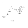
- FIG. 5 illustrates an exemplary diagram of a Euler Axis and a landing assembly.
- FIG. 1 illustrates a block diagram of an exemplary embodiment of an aircraft 100.
- the aircraft 100 includes a nose landing assembly 101, a left landing assembly 103, and a right landing assembly 105.
- the landing assemblies may include, for example, a landing gear assembly that includes an inflatable wheel, or any other device that is operative to contact a landing surface.
- a skid assembly may be used, and portions of the skid assembly may be designated as contact points similar to the gear described above.
- the aircraft 100 includes a processor 102 that is communicatively connected to flight controls 104 and sensors 106 that may include, for example, a gyro sensor, one or more accelerometers, two or more velocity sensors from, for example, a global positioning system (GPS), or any other inertial sensors.
- the processor 102 may also be communicatively connected to a memory 110 and a display 108.
- FIG. 2 illustrates an example of the geometric relationship between a sensor 106, sensor 107 and the nose landing assembly 101 including an example of coordinate systems that are associated with the sensor 106, the sensor 107 and the nose landing assembly 101.
- FIG. 3 illustrates a block diagram of an exemplary embodiment of logic performed by the processor 102 (of FIG. 1 ).
- the input includes acceleration (a i x , a i y , and a i z ) from, for example, an accelerometer, velocity (v i x , v i y , v i z ) from, for example, a GPS or derived from an accelerometer, and a rate of change in orientation (P, Q, R) from, for example, a gyro.
- the processor 102 receives sensor coordinates ( P i sensor ) 303, which includes locations of the sensors, and performs Euler-Axis routine that determines an instant axis of rotation of the aircraft defined as the intersection line of two non-parallel planes as illustrated in FIG. 4 .
- the intersection line, axis of rotation is defined by a unit directional vector u axis and a specific point defined P axis on the axis.
- plane ⁇ is defined by a point P and a normal vector n .
- CPN max v rot 1 ⁇ v rot 2 ⁇ v rot 1 ⁇ v rot 3 ⁇ v rot 2 ⁇ v rot 3
- CPN v rot 1 ⁇ v rot 2 thus selecting sensor_1 and sensor_2 for the detection process.
- the axis-distances routine receives gear coordinates 305 that include locations of the gears P k gear 101, 103, 105 (of FIG. 1 ), and using equations 13 and 14, computes and outputs ⁇ k axis-gear and ⁇ cg parameters defined as the distances from the estimated instant axis of rotation to the extended landing gears end points and the aircraft center of gravity as illustrated in FIG. 5 .
- the detection logic determines if the distance from the axis of rotation to a given gear is the minimum of the axis-distances values and is less than a gear-axis-distance threshold value defined as a gear-cylinder-diameter ⁇ cylinder 307 and the distance from the axis of rotation to center of gravity of the aircraft exceeds the gear-axis-distance threshold value then the detection logic identifies the landing gear as center-of-rotation.
- WoW K if ⁇ min k ⁇ ⁇ axis - gear k ⁇ ⁇ cylinder & ⁇ cg > ⁇ cylinder
- WOW 1 ⁇ left gear
- WOW 2 ⁇ right gear
- WOW 3 ⁇ foward gear.
- the weight on wheel signal may indicate that the aircraft has landed or has taken off from a landing area.
Landscapes
- Engineering & Computer Science (AREA)
- Aviation & Aerospace Engineering (AREA)
- Mechanical Engineering (AREA)
- Force Measurement Appropriate To Specific Purposes (AREA)
- Regulating Braking Force (AREA)
Abstract
Description
- The subject matter disclosed herein relates to detecting impact forces on aircraft, and in particular to detecting landing gear impact on aircraft.
- Aircraft such as, for example, rotary wing aircraft and fixed wing aircraft use a variety of sensors to provide feedback to aircraft control systems. Detecting when a force, such as weight, is applied to the landing assemblies or other portions of an aircraft provides useful feedback to aircraft systems. Previous systems used sensors located on each landing assembly to determine whether weight was applied to a landing assembly. The use of these sensors increased the weight and complexity of the aircraft, and had limited fidelity in sensing actual weight applied to a landing assembly.
- According to one aspect of the invention, a method for sensing a force applied to an aircraft includes defining a first velocity vector as a function of a first velocity due to a rotation motion of the aircraft, defining a second velocity vector as a function of a second velocity due to the rotation motion of the aircraft, defining an instant axis of rotation of the aircraft as a function of the first velocity vector and the second velocity vector, determining whether a force has been exerted on a first portion of the aircraft, and outputting an indication that a force has been exerted on the first portion of the aircraft responsive to determining that the force has been exerted on the first portion of the aircraft.
- According to another aspect of the invention, a system for sensing a force applied to an aircraft includes a first sensor, a second sensor, and a processor operative to define a first velocity vector as a function of a first velocity due to a rotation motion of the aircraft, define a second velocity vector as a function of a second velocity due to the rotation motion of the aircraft, define an instant axis of rotation of the aircraft as a function of the first velocity vector and the second velocity vector, determine whether a force has been exerted on a first portion of the aircraft, and output an indication that a force has been exerted on the first portion of the aircraft responsive to determining that the force has been exerted on the first portion of the aircraft.
- These and other advantages and features will become more apparent from the following description taken in conjunction with the drawings.
Further embodiments of the invention are set out in the following numbered paragraphs: - 1. A method for sensing a force applied to an aircraft, the method comprising:
- defining a first velocity vector as a function of a first velocity due to a rotation motion of the aircraft;
- defining a second velocity vector as a function of a second velocity due to the rotation motion of the aircraft;
- defining an instant axis of rotation of the aircraft as a function of the first velocity vector and the second velocity vector;
- determining whether a force has been exerted on a first portion of the aircraft; and
- outputting an indication that a force has been exerted on the first portion of the aircraft responsive to determining that the force has been exerted on the first portion of the aircraft.
- 2. The method of
paragraph 1, wherein the method further includes determining whether a rate of change of orientation of the aircraft satisfies a minimum rotation norm prior to defining the first and second velocity vectors. - 3. The method of
paragraph 2, wherein the method further includes determining whether a norm of an acceleration due to the rotation motion of the aircraft is greater than a minimum acceleration norm threshold value responsive to determining whether the rate of change of orientation of the aircraft satisfies the minimum rotation norm. - 4. The method of
paragraph 1, wherein the method further includes receiving a first signal from a first sensor indicative of a velocity of the aircraft, an acceleration of the aircraft, and a rate of change of orientation of the aircraft. - 5. The method of
paragraph 1, wherein the first velocity vector is associated with a first sensor, and the second velocity vector is associated with a second sensor. - 6. The method of paragraph 5, wherein the instant axis of rotation of the aircraft is further defined as a function of a position of the first sensor and a position of the second sensor.
- 7. The method of
paragraph 1, wherein the defining the instant axis of rotation includes defining the instant axis of rotation as a line of intersection between a first plane perpendicular to the first velocity vector and a second plane perpendicular to the second velocity vector, wherein the first plane is not parallel to the second plane. - 8. The method of
paragraph 1, wherein the determining whether a force has been exerted on a portion of the aircraft includes:- calculating a distance between the first portion of the aircraft and the instant axis of rotation;
- calculating a distance between a center of gravity of the aircraft and the instant axis of rotation;
- determining whether the distance between the first portion of the aircraft and the instant axis of rotation is a minimum of an set of axis of rotation distance values, and whether the distance between the portion of the aircraft and the instant axis of rotation is less than a gear-axis-distance threshold value; and
- determining whether the distance between a center of gravity of the aircraft and the instant axis of rotation exceeds the gear-axis-distance threshold value.
- 9. The method of
paragraph 1, wherein the force applied to the first portion of the aircraft is a weight on wheel force. - 10. The method of
paragraph 1, wherein the first portion of the aircraft includes a landing gear assembly. - 11. A system for sensing a force applied to an aircraft comprising:
- a first sensor;
- a second sensor; and
- a processor operative to define a first velocity vector as a function of a first velocity due to a rotation motion of the aircraft, define a second velocity vector as a function of a second velocity due to the rotation motion of the aircraft, define an instant axis of rotation of the aircraft as a function of the first velocity vector and the second velocity vector, determine whether a force has been exerted on a first portion of the aircraft, and output an indication that a force has been exerted on the first portion of the aircraft responsive to determining that the force has been exerted on the first portion of the aircraft.
- 12. The system of
paragraph 11, wherein the processor is further operative to determine whether a rate of change of orientation of the aircraft satisfies a minimum rotation norm prior to defining the first and second velocity vectors. - 13. The system of
paragraph 12, wherein the processor is further operative to determine whether a norm of an acceleration due to the rotation motion of the aircraft is greater than a minimum acceleration norm threshold value responsive to determining whether the rate of change of orientation of the aircraft satisfies the minimum rotation norm. - 14. The system of
paragraph 11, wherein the processor is further operative to receive a first signal from the first sensor indicative of a velocity of the aircraft, an acceleration of the aircraft, and a rate of change of orientation of the aircraft. - 15. The system of
paragraph 11, wherein the first velocity vector is associated with a first sensor, and the second velocity vector is associated with a second sensor. - 16. The system of
paragraph 15, wherein the instant axis of rotation of the aircraft is further defined as a function of a position of the first sensor and a position of the second sensor. - 17. The system of
paragraph 11, wherein the defining the instant axis of rotation includes defining the instant axis of rotation as a line of intersection between a first plane perpendicular to the first velocity vector and a second plane perpendicular to the second velocity vector, wherein the first plane is not parallel to the second plane. - 18. The system of
paragraph 11, wherein the determining whether a force has been exerted on a portion of the aircraft includes:- calculating a distance between the first portion of the aircraft and the instant axis of rotation;
- calculating a distance between a center of gravity of the aircraft and the instant axis of rotation;
- determining whether the distance between the first portion of the aircraft and the instant axis of rotation is a minimum of a set of axis of rotation distance values, and whether the distance between the portion of the aircraft and the instant axis of rotation is less than a gear-axis-distance threshold value; and
- determining whether the distance between a center of gravity of the aircraft and the instant axis of rotation exceeds the gear-axis-distance threshold value.
- 19. The system of
paragraph 11, wherein the force applied to the first portion of the aircraft is a weight on wheel force. - 20. The system of
paragraph 11, wherein the first portion of the aircraft includes a landing gear assembly. - The subject matter which is regarded as the invention is particularly pointed out and distinctly claimed in the claims at the conclusion of the specification. The foregoing and other features, and advantages of the invention are apparent from the following detailed description taken in conjunction with the accompanying drawings in which:
-
FIG. 1 illustrates a block diagram of an exemplary embodiment of anaircraft 100. -
FIG. 2 illustrates an example of the geometric relationship between sensors and a nose landing assembly ofFIG. 1 . -
FIG. 3 illustrates a block diagram of an exemplary embodiment of logic performed by the processor ofFIG. 1 . -
FIG. 4 illustrates an exemplary diagram of a Euler Axis estimation. -
FIG. 5 illustrates an exemplary diagram of a Euler Axis and a landing assembly. - The detailed description explains embodiments of the invention, together with advantages and features, by way of example with reference to the drawings.
-
FIG. 1 illustrates a block diagram of an exemplary embodiment of anaircraft 100. Theaircraft 100 includes anose landing assembly 101, aleft landing assembly 103, and aright landing assembly 105. The landing assemblies may include, for example, a landing gear assembly that includes an inflatable wheel, or any other device that is operative to contact a landing surface. For example a skid assembly may be used, and portions of the skid assembly may be designated as contact points similar to the gear described above. Theaircraft 100 includes aprocessor 102 that is communicatively connected toflight controls 104 andsensors 106 that may include, for example, a gyro sensor, one or more accelerometers, two or more velocity sensors from, for example, a global positioning system (GPS), or any other inertial sensors. Theprocessor 102 may also be communicatively connected to amemory 110 and adisplay 108. -
FIG. 2 illustrates an example of the geometric relationship between asensor 106,sensor 107 and thenose landing assembly 101 including an example of coordinate systems that are associated with thesensor 106, thesensor 107 and thenose landing assembly 101. -
FIG. 3 illustrates a block diagram of an exemplary embodiment of logic performed by the processor 102 (ofFIG. 1 ). In this regard, theprocessor 102 receives input data from the sensors (sensors_i; where i=1, 2, 3,...)106. The input includes acceleration (ai x, ai y, and ai z) from, for example, an accelerometer, velocity (vi x, vi y, vi z) from, for example, a GPS or derived from an accelerometer, and a rate of change in orientation (P, Q, R) from, for example, a gyro. Inblock 302, theprocessor 102 performs an initialization routine that receives minimum rotation parameters (α, β, γ) 301 where α is the minimum angular velocity norm threshold value, β is the minimum angular velocity derivative norm threshold value and γ is the minimum acceleration norm threshold value, and determines whether a minimum rotation norm (MRN) condition has been satisfied as follows:
- The
processor 102 resets the aircraft velocities and accelerations values as follows:
- Thereafter the initialization routine outputs velocities and accelerations due to the rotation motion of the aircraft only (


- The initialization routine determines whether the acceleration norm due to the rotation motion of the aircraft exceed the acceleration norm threshold value (γ) to output an enabling signal (Enable) to enable the landing detection process, as follows:

- In
block 304 theprocessor 102 receives sensor coordinates (Pi sensor ) 303, which includes locations of the sensors, and performs Euler-Axis routine that determines an instant axis of rotation of the aircraft defined as the intersection line of two non-parallel planes as illustrated inFIG. 4 . Geometrically, the intersection line, axis of rotation, is defined by a unit directional vector uaxis and a specific point defined Paxis on the axis. The parametric equation of the axis of rotation is given by:
- In a three dimensional space, plane Δ is defined by a point P and a normal vector n. Two planes Δ1 and Δ2 are not parallel if their normal vectors n 1 and n 2 are not parallel; this is equivalent to the cross product norm condition (CPN), where CPN = |n 1×n 2| ≥ µ >> 0. To determine the axis of rotation directional unit vector uaxis ; the best two non parallel velocity vectors are selected by maximizing CPN, where:

- In vector space, the axis of rotation directional unit vector is given by:

- To simplify the example,

- To determine the intersection line, axis of rotation, a specific point is found on the line, that is, to find a point P axis that lies in both planes Δ1 and Δ2, thereby solving implicit equations of Δ1 and Δ2 for P axis :

- Equivalently solving for three coordinates Paxis_x, Paxis_y , and Paxis_z :

- Where d1 and d2 are known constants given by:

- For a robust solution of Equation 9, a direct linear equation algorithm is used. First a largest absolute coordinate value, noted δ, of uaxis given by
equation 7, is selected by:
- Depending of the value of δ from
equation 11, the corresponding coordinate of Paxis is set to zero. Solving for the two other coordinates, the equation 9 gives the general solution for Paxis expressed as: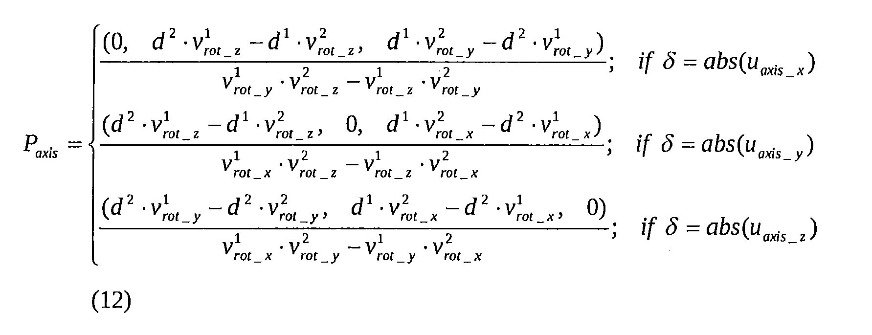
- In
block 306, the axis-distances routine receives gear coordinates 305 that include locations of thegears P FIG. 1 ), and usingequations 13 and 14, computes and outputs λ k axis-gear and λ cg parameters defined as the distances from the estimated instant axis of rotation to the extended landing gears end points and the aircraft center of gravity as illustrated inFIG. 5 .

- In
block 308, the detection logic determines if the distance from the axis of rotation to a given gear is the minimum of the axis-distances values and is less than a gear-axis-distance threshold value defined as a gear-cylinder-diameter λ cylinder 307 and the distance from the axis of rotation to center of gravity of the aircraft exceeds the gear-axis-distance threshold value then the detection logic identifies the landing gear as center-of-rotation. The detection logic outputs a weight on wheel (force on wheel) signal 310 indicating contact:
With: WOW=1→ left gear; WOW=2→ right gear; WOW=3 → foward gear. - The gear WoW signal 310 in figure
- 3 indicates that a weight on wheel has occurred on the gear. The indication provides information to the
aircraft 100 operator and/or automatic control systems of theaircraft 100 that assists in operating the aircraft. Particularly, the weight on wheel signal may indicate that the aircraft has landed or has taken off from a landing area. - While the invention has been described in detail in connection with only a limited number of embodiments, it should be readily understood that the invention is not limited to such disclosed embodiments. Rather, the invention can be modified to incorporate any number of variations, alterations, substitutions or equivalent arrangements not heretofore described, but which are commensurate with the spirit and scope of the invention. Additionally, while various embodiments of the invention have been described, it is to be understood that aspects of the invention may include only some of the described embodiments. Accordingly, the invention is not to be seen as limited by the foregoing description, but is only limited by the scope of the appended claims.
Claims (15)
- A method for sensing a force applied to an aircraft, the method comprising:defining a first velocity vector as a function of a first velocity due to a rotation motion of the aircraft;defining a second velocity vector as a function of a second velocity due to the rotation motion of the aircraft;defining an instant axis of rotation of the aircraft as a function of the first velocity vector and the second velocity vector;determining whether a force has been exerted on a first portion of the aircraft; andoutputting an indication that a force has been exerted on the first portion of the aircraft responsive to determining that the force has been exerted on the first portion of the aircraft.
- The method of claim 1, wherein the method further includes determining whether a rate of change of orientation of the aircraft satisfies a minimum rotation norm prior to defining the first and second velocity vectors.
- The method of claim 2, wherein the method further includes determining whether a norm of an acceleration due to the rotation motion of the aircraft is greater than a minimum acceleration norm threshold value responsive to determining whether the rate of change of orientation of the aircraft satisfies the minimum rotation norm.
- The method of any of the preceding claims, wherein the method further includes receiving a first signal from a first sensor indicative of a velocity of the aircraft, an acceleration of the aircraft, and a rate of change of orientation of the aircraft.
- The method of any of the preceding claims, wherein the first velocity vector is associated with a first sensor, and the second velocity vector is associated with a second sensor and/or wherein the instant axis of rotation of the aircraft is further defined as a function of a position of the first sensor and a position of the second sensor.
- The method of any of the preceding claims, wherein the defining the instant axis of rotation includes defining the instant axis of rotation as a line of intersection between a first plane perpendicular to the first velocity vector and a second plane perpendicular to the second velocity vector, wherein the first plane is not parallel to the second plane.
- The method of any of the preceding claims, wherein the determining whether a force has been exerted on a portion of the aircraft includes:calculating a distance between the first portion of the aircraft and the instant axis of rotation;calculating a distance between a center of gravity of the aircraft and the instant axis of rotation;determining whether the distance between the first portion of the aircraft and the instant axis of rotation is a minimum of an set of axis of rotation distance values, and whether the distance between the portion of the aircraft and the instant axis of rotation is less than a gear-axis-distance threshold value; anddetermining whether the distance between a center of gravity of the aircraft and the instant axis of rotation exceeds the gear-axis-distance threshold value.
- The method of any of the preceding claims, wherein the force applied to the first portion of the aircraft is a weight on wheel force and/or wherein the first portion of the aircraft includes a landing gear assembly.
- A system for sensing a force applied to an aircraft comprising:a first sensor;a second sensor; anda processor operative to define a first velocity vector as a function of a first velocity due to a rotation motion of the aircraft, define a second velocity vector as a function of a second velocity due to the rotation motion of the aircraft, define an instant axis of rotation of the aircraft as a function of the first velocity vector and the second velocity vector, determine whether a force has been exerted on a first portion of the aircraft, and output an indication that a force has been exerted on the first portion of the aircraft responsive to determining that the force has been exerted on the first portion of the aircraft.
- The system of claim 9, wherein the processor is further operative to determine whether a rate of change of orientation of the aircraft satisfies a minimum rotation norm prior to defining the first and second velocity vectors and/or wherein the processor is further operative to determine whether a norm of an acceleration due to the rotation motion of the aircraft is greater than a minimum acceleration norm threshold value responsive to determining whether the rate of change of orientation of the aircraft satisfies the minimum rotation norm.
- The system of claim 9 or 10, wherein the processor is further operative to receive a first signal from the first sensor indicative of a velocity of the aircraft, an acceleration of the aircraft, and a rate of change of orientation of the aircraft.
- The system of any of claims 9 to 11, wherein the first velocity vector is associated with a first sensor, and the second velocity vector is associated with a second sensor and/or wherein the instant axis of rotation of the aircraft is further defined as a function of a position of the first sensor and a position of the second sensor.
- The system of any of claims 9 to 12, wherein the defining the instant axis of rotation includes defining the instant axis of rotation as a line of intersection between a first plane perpendicular to the first velocity vector and a second plane perpendicular to the second velocity vector, wherein the first plane is not parallel to the second plane.
- The system of any of claims 9 to 13, wherein the determining whether a force has been exerted on a portion of the aircraft includes:calculating a distance between the first portion of the aircraft and the instant axis of rotation;calculating a distance between a center of gravity of the aircraft and the instant axis of rotation;determining whether the distance between the first portion of the aircraft and the instant axis of rotation is a minimum of a set of axis of rotation distance values, and whether the distance between the portion of the aircraft and the instant axis of rotation is less than a gear-axis-distance threshold value; anddetermining whether the distance between a center of gravity of the aircraft and the instant axis of rotation exceeds the gear-axis-distance threshold value.
- The system of any of claims 9 to 14, wherein the force applied to the first portion of the aircraft is a weight on wheel force and/or wherein the first portion of the aircraft includes a landing gear assembly.
Applications Claiming Priority (1)
| Application Number | Priority Date | Filing Date | Title |
|---|---|---|---|
| US13/077,084 US8862377B2 (en) | 2011-03-31 | 2011-03-31 | Method and system for detecting forces on aircraft |
Publications (3)
| Publication Number | Publication Date |
|---|---|
| EP2505498A2 true EP2505498A2 (en) | 2012-10-03 |
| EP2505498A3 EP2505498A3 (en) | 2017-12-20 |
| EP2505498B1 EP2505498B1 (en) | 2019-09-11 |
Family
ID=46000744
Family Applications (1)
| Application Number | Title | Priority Date | Filing Date |
|---|---|---|---|
| EP12162069.4A Active EP2505498B1 (en) | 2011-03-31 | 2012-03-29 | Method and system for detecting forces on aircraft |
Country Status (2)
| Country | Link |
|---|---|
| US (1) | US8862377B2 (en) |
| EP (1) | EP2505498B1 (en) |
Families Citing this family (1)
| Publication number | Priority date | Publication date | Assignee | Title |
|---|---|---|---|---|
| EP3336485B1 (en) | 2016-12-15 | 2020-09-23 | Safran Landing Systems UK Limited | Aircraft assembly including deflection sensor |
Family Cites Families (24)
| Publication number | Priority date | Publication date | Assignee | Title |
|---|---|---|---|---|
| US3499500A (en) | 1968-02-29 | 1970-03-10 | Boeing Co | Strain-gauge weighing apparatus for vehicle support structure |
| DE3231162C2 (en) * | 1982-08-21 | 1984-08-16 | Messerschmitt-Bölkow-Blohm GmbH, 8000 München | Procedure for the accelerated bringing about of the ground contact of airplanes |
| US4638437A (en) | 1984-06-25 | 1987-01-20 | The Boeing Company | Aircraft performance margin indicator |
| US4815678A (en) | 1987-12-04 | 1989-03-28 | The Boeing Company | Pivotally mounted high energy absorbing aircraft tail skid assembly having predetermined failure mode |
| DE3803015A1 (en) | 1988-02-02 | 1989-08-10 | Pfister Gmbh | Method and system for operating (driving) an aircraft |
| US4980835A (en) | 1988-10-13 | 1990-12-25 | United Technologies Corporation | Control law system for X-Wing aircraft |
| US5446666A (en) | 1994-05-17 | 1995-08-29 | The Boeing Company | Ground state-fly state transition control for unique-trim aircraft flight control system |
| US5826833A (en) | 1995-05-15 | 1998-10-27 | The Boeing Company | System for providing an air/ground signal to aircraft flight control systems |
| BR9510630A (en) | 1995-09-14 | 1999-01-05 | Sikorsky Aircraft Corp | Landing gear / mouthpiece energy absorbers including device to indicate the magnitude of impact loads |
| US6043759A (en) | 1996-07-29 | 2000-03-28 | Alliedsignal | Air-ground logic system and method for rotary wing aircraft |
| JPH11105797A (en) * | 1997-10-07 | 1999-04-20 | Mitsubishi Electric Corp | Landing gear |
| US6052069A (en) | 1997-10-29 | 2000-04-18 | Sikorsky Aircraft Corporation | Taxi and slope landing symbology for a helicopter |
| US6189836B1 (en) | 1998-09-25 | 2001-02-20 | Sikorsky Aircraft Corporation | Model-following control system using acceleration feedback |
| US20040078170A1 (en) * | 2002-10-17 | 2004-04-22 | Don Di Marzio | System and method for monitoring a structure |
| JP2005059656A (en) | 2003-08-08 | 2005-03-10 | Fuji Heavy Ind Ltd | Flying object landing control device and flying object landing control method |
| US6854689B1 (en) | 2004-02-09 | 2005-02-15 | The Boeing Company | Methods and systems for operating aircraft landing gears |
| US7742846B2 (en) | 2006-06-02 | 2010-06-22 | Sikorsky Aircraft Corporation | Surface contact override landing scheme for a FBW rotary-wing aircraft |
| US20080215198A1 (en) * | 2006-09-22 | 2008-09-04 | Richards Robert E | Method and apparatus for providing takeoff runway information and predicting end of runway overrun |
| US20080099602A1 (en) * | 2006-09-29 | 2008-05-01 | Zyss Michael J | System and method for detecting ground contact status of an air vehicle |
| US20080114506A1 (en) * | 2006-11-10 | 2008-05-15 | Davis Christopher L | Hard landing detection |
| US7967244B2 (en) * | 2006-11-16 | 2011-06-28 | The Boeing Company | Onboard aircraft weight and balance system |
| GB2453554B (en) * | 2007-10-09 | 2012-03-14 | Messier Dowty Ltd | Load detection in an aircraft landing gear |
| JP2011504835A (en) * | 2007-11-29 | 2011-02-17 | エアバス・オペレーションズ・ゲーエムベーハー | Apparatus and method for testing an aircraft pedal system |
| US20120095802A1 (en) * | 2010-10-18 | 2012-04-19 | The Coca-Cola Company | System and methods for evaluating political, social, and economic risk associated with a geographic region |
-
2011
- 2011-03-31 US US13/077,084 patent/US8862377B2/en active Active
-
2012
- 2012-03-29 EP EP12162069.4A patent/EP2505498B1/en active Active
Non-Patent Citations (1)
| Title |
|---|
| None |
Also Published As
| Publication number | Publication date |
|---|---|
| EP2505498B1 (en) | 2019-09-11 |
| EP2505498A3 (en) | 2017-12-20 |
| US8862377B2 (en) | 2014-10-14 |
| US20120253652A1 (en) | 2012-10-04 |
Similar Documents
| Publication | Publication Date | Title |
|---|---|---|
| EP2077432B1 (en) | Moving object with tilt angle estimating mechanism | |
| US9327842B2 (en) | Method and system for detecting forces on aircraft | |
| JP5036462B2 (en) | Navigation system and navigation method | |
| US9183463B2 (en) | Orientation model for a sensor system | |
| EP3006899B1 (en) | Systems and methods for attitude fault detection based on air data and aircraft control settings | |
| US9428279B2 (en) | Systems and methods for airspeed estimation using actuation signals | |
| KR20210029518A (en) | Multi-sensor based unmanned aerial vehicle and its control method | |
| EP1983301A2 (en) | Inertial measurement unit fault detection isolation reconfiguration using parity logic | |
| EP2964502B1 (en) | Method for calculating a desired yaw rate for a vehicle | |
| US20200386782A1 (en) | Apparatus and method for calibrating inertial measuring unit | |
| WO2023071442A1 (en) | Data processing method and apparatus | |
| WO2014148989A1 (en) | Control system for autonomous vehicles, and a method for the control system | |
| US20180149480A1 (en) | System for incremental trajectory estimation based on real time inertial sensing | |
| RU2762143C2 (en) | System for determining course and angular spatial position made with the possibility of functioning in polar region | |
| EP3988416A1 (en) | Method and system for driving surface friction characteristic determination | |
| EP2529958A2 (en) | System, method, and program for detecting deflated tires | |
| JP5219547B2 (en) | Car navigation system and navigation method | |
| EP2505498A2 (en) | Method and system for detecting forces on aircraft | |
| EP4033205A1 (en) | Systems and methods for model based vehicle navigation | |
| KR101146748B1 (en) | Apparatus and method for controlling attitude of a aircraft | |
| US12306205B2 (en) | Method and system for estimating aerodynamic angles of a flying body | |
| KR20210090994A (en) | Navigation system, apparatus and method for estimating navigation error | |
| JP6409625B2 (en) | Vehicle position calculation device | |
| KR20190079470A (en) | Method and apparatus for determining object position | |
| KR101638886B1 (en) | Precise estimation mechanism and apparatus of yaw rate and yaw angle of vehicle |
Legal Events
| Date | Code | Title | Description |
|---|---|---|---|
| PUAI | Public reference made under article 153(3) epc to a published international application that has entered the european phase |
Free format text: ORIGINAL CODE: 0009012 |
|
| AK | Designated contracting states |
Kind code of ref document: A2 Designated state(s): AL AT BE BG CH CY CZ DE DK EE ES FI FR GB GR HR HU IE IS IT LI LT LU LV MC MK MT NL NO PL PT RO RS SE SI SK SM TR |
|
| AX | Request for extension of the european patent |
Extension state: BA ME |
|
| PUAL | Search report despatched |
Free format text: ORIGINAL CODE: 0009013 |
|
| AK | Designated contracting states |
Kind code of ref document: A3 Designated state(s): AL AT BE BG CH CY CZ DE DK EE ES FI FR GB GR HR HU IE IS IT LI LT LU LV MC MK MT NL NO PL PT RO RS SE SI SK SM TR |
|
| AX | Request for extension of the european patent |
Extension state: BA ME |
|
| RIC1 | Information provided on ipc code assigned before grant |
Ipc: B64D 45/00 20060101ALI20171113BHEP Ipc: B64C 25/00 20060101AFI20171113BHEP |
|
| STAA | Information on the status of an ep patent application or granted ep patent |
Free format text: STATUS: REQUEST FOR EXAMINATION WAS MADE |
|
| 17P | Request for examination filed |
Effective date: 20180620 |
|
| RBV | Designated contracting states (corrected) |
Designated state(s): AL AT BE BG CH CY CZ DE DK EE ES FI FR GB GR HR HU IE IS IT LI LT LU LV MC MK MT NL NO PL PT RO RS SE SI SK SM TR |
|
| GRAP | Despatch of communication of intention to grant a patent |
Free format text: ORIGINAL CODE: EPIDOSNIGR1 |
|
| STAA | Information on the status of an ep patent application or granted ep patent |
Free format text: STATUS: GRANT OF PATENT IS INTENDED |
|
| INTG | Intention to grant announced |
Effective date: 20190320 |
|
| GRAS | Grant fee paid |
Free format text: ORIGINAL CODE: EPIDOSNIGR3 |
|
| GRAA | (expected) grant |
Free format text: ORIGINAL CODE: 0009210 |
|
| STAA | Information on the status of an ep patent application or granted ep patent |
Free format text: STATUS: THE PATENT HAS BEEN GRANTED |
|
| AK | Designated contracting states |
Kind code of ref document: B1 Designated state(s): AL AT BE BG CH CY CZ DE DK EE ES FI FR GB GR HR HU IE IS IT LI LT LU LV MC MK MT NL NO PL PT RO RS SE SI SK SM TR |
|
| REG | Reference to a national code |
Ref country code: GB Ref legal event code: FG4D |
|
| REG | Reference to a national code |
Ref country code: CH Ref legal event code: EP |
|
| REG | Reference to a national code |
Ref country code: AT Ref legal event code: REF Ref document number: 1178127 Country of ref document: AT Kind code of ref document: T Effective date: 20190915 |
|
| REG | Reference to a national code |
Ref country code: DE Ref legal event code: R096 Ref document number: 602012063811 Country of ref document: DE Ref country code: IE Ref legal event code: FG4D |
|
| REG | Reference to a national code |
Ref country code: NL Ref legal event code: MP Effective date: 20190911 |
|
| REG | Reference to a national code |
Ref country code: LT Ref legal event code: MG4D |
|
| PG25 | Lapsed in a contracting state [announced via postgrant information from national office to epo] |
Ref country code: NO Free format text: LAPSE BECAUSE OF FAILURE TO SUBMIT A TRANSLATION OF THE DESCRIPTION OR TO PAY THE FEE WITHIN THE PRESCRIBED TIME-LIMIT Effective date: 20191211 Ref country code: LT Free format text: LAPSE BECAUSE OF FAILURE TO SUBMIT A TRANSLATION OF THE DESCRIPTION OR TO PAY THE FEE WITHIN THE PRESCRIBED TIME-LIMIT Effective date: 20190911 Ref country code: BG Free format text: LAPSE BECAUSE OF FAILURE TO SUBMIT A TRANSLATION OF THE DESCRIPTION OR TO PAY THE FEE WITHIN THE PRESCRIBED TIME-LIMIT Effective date: 20191211 Ref country code: HR Free format text: LAPSE BECAUSE OF FAILURE TO SUBMIT A TRANSLATION OF THE DESCRIPTION OR TO PAY THE FEE WITHIN THE PRESCRIBED TIME-LIMIT Effective date: 20190911 Ref country code: SE Free format text: LAPSE BECAUSE OF FAILURE TO SUBMIT A TRANSLATION OF THE DESCRIPTION OR TO PAY THE FEE WITHIN THE PRESCRIBED TIME-LIMIT Effective date: 20190911 Ref country code: FI Free format text: LAPSE BECAUSE OF FAILURE TO SUBMIT A TRANSLATION OF THE DESCRIPTION OR TO PAY THE FEE WITHIN THE PRESCRIBED TIME-LIMIT Effective date: 20190911 |
|
| PG25 | Lapsed in a contracting state [announced via postgrant information from national office to epo] |
Ref country code: AL Free format text: LAPSE BECAUSE OF FAILURE TO SUBMIT A TRANSLATION OF THE DESCRIPTION OR TO PAY THE FEE WITHIN THE PRESCRIBED TIME-LIMIT Effective date: 20190911 Ref country code: ES Free format text: LAPSE BECAUSE OF FAILURE TO SUBMIT A TRANSLATION OF THE DESCRIPTION OR TO PAY THE FEE WITHIN THE PRESCRIBED TIME-LIMIT Effective date: 20190911 Ref country code: GR Free format text: LAPSE BECAUSE OF FAILURE TO SUBMIT A TRANSLATION OF THE DESCRIPTION OR TO PAY THE FEE WITHIN THE PRESCRIBED TIME-LIMIT Effective date: 20191212 Ref country code: RS Free format text: LAPSE BECAUSE OF FAILURE TO SUBMIT A TRANSLATION OF THE DESCRIPTION OR TO PAY THE FEE WITHIN THE PRESCRIBED TIME-LIMIT Effective date: 20190911 Ref country code: LV Free format text: LAPSE BECAUSE OF FAILURE TO SUBMIT A TRANSLATION OF THE DESCRIPTION OR TO PAY THE FEE WITHIN THE PRESCRIBED TIME-LIMIT Effective date: 20190911 |
|
| REG | Reference to a national code |
Ref country code: AT Ref legal event code: MK05 Ref document number: 1178127 Country of ref document: AT Kind code of ref document: T Effective date: 20190911 |
|
| PG25 | Lapsed in a contracting state [announced via postgrant information from national office to epo] |
Ref country code: RO Free format text: LAPSE BECAUSE OF FAILURE TO SUBMIT A TRANSLATION OF THE DESCRIPTION OR TO PAY THE FEE WITHIN THE PRESCRIBED TIME-LIMIT Effective date: 20190911 Ref country code: IT Free format text: LAPSE BECAUSE OF FAILURE TO SUBMIT A TRANSLATION OF THE DESCRIPTION OR TO PAY THE FEE WITHIN THE PRESCRIBED TIME-LIMIT Effective date: 20190911 Ref country code: PL Free format text: LAPSE BECAUSE OF FAILURE TO SUBMIT A TRANSLATION OF THE DESCRIPTION OR TO PAY THE FEE WITHIN THE PRESCRIBED TIME-LIMIT Effective date: 20190911 Ref country code: EE Free format text: LAPSE BECAUSE OF FAILURE TO SUBMIT A TRANSLATION OF THE DESCRIPTION OR TO PAY THE FEE WITHIN THE PRESCRIBED TIME-LIMIT Effective date: 20190911 Ref country code: AT Free format text: LAPSE BECAUSE OF FAILURE TO SUBMIT A TRANSLATION OF THE DESCRIPTION OR TO PAY THE FEE WITHIN THE PRESCRIBED TIME-LIMIT Effective date: 20190911 Ref country code: NL Free format text: LAPSE BECAUSE OF FAILURE TO SUBMIT A TRANSLATION OF THE DESCRIPTION OR TO PAY THE FEE WITHIN THE PRESCRIBED TIME-LIMIT Effective date: 20190911 Ref country code: PT Free format text: LAPSE BECAUSE OF FAILURE TO SUBMIT A TRANSLATION OF THE DESCRIPTION OR TO PAY THE FEE WITHIN THE PRESCRIBED TIME-LIMIT Effective date: 20200113 |
|
| PGFP | Annual fee paid to national office [announced via postgrant information from national office to epo] |
Ref country code: GB Payment date: 20200327 Year of fee payment: 9 Ref country code: DE Payment date: 20200327 Year of fee payment: 9 |
|
| PG25 | Lapsed in a contracting state [announced via postgrant information from national office to epo] |
Ref country code: IS Free format text: LAPSE BECAUSE OF FAILURE TO SUBMIT A TRANSLATION OF THE DESCRIPTION OR TO PAY THE FEE WITHIN THE PRESCRIBED TIME-LIMIT Effective date: 20200224 Ref country code: CZ Free format text: LAPSE BECAUSE OF FAILURE TO SUBMIT A TRANSLATION OF THE DESCRIPTION OR TO PAY THE FEE WITHIN THE PRESCRIBED TIME-LIMIT Effective date: 20190911 Ref country code: SK Free format text: LAPSE BECAUSE OF FAILURE TO SUBMIT A TRANSLATION OF THE DESCRIPTION OR TO PAY THE FEE WITHIN THE PRESCRIBED TIME-LIMIT Effective date: 20190911 Ref country code: SM Free format text: LAPSE BECAUSE OF FAILURE TO SUBMIT A TRANSLATION OF THE DESCRIPTION OR TO PAY THE FEE WITHIN THE PRESCRIBED TIME-LIMIT Effective date: 20190911 |
|
| REG | Reference to a national code |
Ref country code: DE Ref legal event code: R097 Ref document number: 602012063811 Country of ref document: DE |
|
| PGFP | Annual fee paid to national office [announced via postgrant information from national office to epo] |
Ref country code: FR Payment date: 20200325 Year of fee payment: 9 |
|
| PLBE | No opposition filed within time limit |
Free format text: ORIGINAL CODE: 0009261 |
|
| STAA | Information on the status of an ep patent application or granted ep patent |
Free format text: STATUS: NO OPPOSITION FILED WITHIN TIME LIMIT |
|
| PG2D | Information on lapse in contracting state deleted |
Ref country code: IS |
|
| PG25 | Lapsed in a contracting state [announced via postgrant information from national office to epo] |
Ref country code: DK Free format text: LAPSE BECAUSE OF FAILURE TO SUBMIT A TRANSLATION OF THE DESCRIPTION OR TO PAY THE FEE WITHIN THE PRESCRIBED TIME-LIMIT Effective date: 20190911 Ref country code: IS Free format text: LAPSE BECAUSE OF FAILURE TO SUBMIT A TRANSLATION OF THE DESCRIPTION OR TO PAY THE FEE WITHIN THE PRESCRIBED TIME-LIMIT Effective date: 20200112 |
|
| 26N | No opposition filed |
Effective date: 20200615 |
|
| PG25 | Lapsed in a contracting state [announced via postgrant information from national office to epo] |
Ref country code: SI Free format text: LAPSE BECAUSE OF FAILURE TO SUBMIT A TRANSLATION OF THE DESCRIPTION OR TO PAY THE FEE WITHIN THE PRESCRIBED TIME-LIMIT Effective date: 20190911 |
|
| PG25 | Lapsed in a contracting state [announced via postgrant information from national office to epo] |
Ref country code: MC Free format text: LAPSE BECAUSE OF FAILURE TO SUBMIT A TRANSLATION OF THE DESCRIPTION OR TO PAY THE FEE WITHIN THE PRESCRIBED TIME-LIMIT Effective date: 20190911 |
|
| REG | Reference to a national code |
Ref country code: CH Ref legal event code: PL |
|
| REG | Reference to a national code |
Ref country code: BE Ref legal event code: MM Effective date: 20200331 |
|
| PG25 | Lapsed in a contracting state [announced via postgrant information from national office to epo] |
Ref country code: LU Free format text: LAPSE BECAUSE OF NON-PAYMENT OF DUE FEES Effective date: 20200329 |
|
| PG25 | Lapsed in a contracting state [announced via postgrant information from national office to epo] |
Ref country code: CH Free format text: LAPSE BECAUSE OF NON-PAYMENT OF DUE FEES Effective date: 20200331 Ref country code: LI Free format text: LAPSE BECAUSE OF NON-PAYMENT OF DUE FEES Effective date: 20200331 Ref country code: IE Free format text: LAPSE BECAUSE OF NON-PAYMENT OF DUE FEES Effective date: 20200329 |
|
| PG25 | Lapsed in a contracting state [announced via postgrant information from national office to epo] |
Ref country code: BE Free format text: LAPSE BECAUSE OF NON-PAYMENT OF DUE FEES Effective date: 20200331 |
|
| REG | Reference to a national code |
Ref country code: DE Ref legal event code: R119 Ref document number: 602012063811 Country of ref document: DE |
|
| GBPC | Gb: european patent ceased through non-payment of renewal fee |
Effective date: 20210329 |
|
| PG25 | Lapsed in a contracting state [announced via postgrant information from national office to epo] |
Ref country code: FR Free format text: LAPSE BECAUSE OF NON-PAYMENT OF DUE FEES Effective date: 20210331 Ref country code: GB Free format text: LAPSE BECAUSE OF NON-PAYMENT OF DUE FEES Effective date: 20210329 Ref country code: DE Free format text: LAPSE BECAUSE OF NON-PAYMENT OF DUE FEES Effective date: 20211001 |
|
| PG25 | Lapsed in a contracting state [announced via postgrant information from national office to epo] |
Ref country code: TR Free format text: LAPSE BECAUSE OF FAILURE TO SUBMIT A TRANSLATION OF THE DESCRIPTION OR TO PAY THE FEE WITHIN THE PRESCRIBED TIME-LIMIT Effective date: 20190911 Ref country code: MT Free format text: LAPSE BECAUSE OF FAILURE TO SUBMIT A TRANSLATION OF THE DESCRIPTION OR TO PAY THE FEE WITHIN THE PRESCRIBED TIME-LIMIT Effective date: 20190911 Ref country code: CY Free format text: LAPSE BECAUSE OF FAILURE TO SUBMIT A TRANSLATION OF THE DESCRIPTION OR TO PAY THE FEE WITHIN THE PRESCRIBED TIME-LIMIT Effective date: 20190911 |
|
| PG25 | Lapsed in a contracting state [announced via postgrant information from national office to epo] |
Ref country code: MK Free format text: LAPSE BECAUSE OF FAILURE TO SUBMIT A TRANSLATION OF THE DESCRIPTION OR TO PAY THE FEE WITHIN THE PRESCRIBED TIME-LIMIT Effective date: 20190911 |