EP2505389A1 - Fahrzeugluftreifen - Google Patents
Fahrzeugluftreifen Download PDFInfo
- Publication number
- EP2505389A1 EP2505389A1 EP12153973A EP12153973A EP2505389A1 EP 2505389 A1 EP2505389 A1 EP 2505389A1 EP 12153973 A EP12153973 A EP 12153973A EP 12153973 A EP12153973 A EP 12153973A EP 2505389 A1 EP2505389 A1 EP 2505389A1
- Authority
- EP
- European Patent Office
- Prior art keywords
- incisions
- tread
- vehicle tire
- pneumatic vehicle
- tire according
- Prior art date
- Legal status (The legal status is an assumption and is not a legal conclusion. Google has not performed a legal analysis and makes no representation as to the accuracy of the status listed.)
- Granted
Links
Images


Classifications
-
- B—PERFORMING OPERATIONS; TRANSPORTING
- B60—VEHICLES IN GENERAL
- B60C—VEHICLE TYRES; TYRE INFLATION; TYRE CHANGING; CONNECTING VALVES TO INFLATABLE ELASTIC BODIES IN GENERAL; DEVICES OR ARRANGEMENTS RELATED TO TYRES
- B60C11/00—Tyre tread bands; Tread patterns; Anti-skid inserts
- B60C11/03—Tread patterns
- B60C11/12—Tread patterns characterised by the use of narrow slits or incisions, e.g. sipes
- B60C11/1259—Depth of the sipe
- B60C11/1263—Depth of the sipe different within the same sipe
-
- B—PERFORMING OPERATIONS; TRANSPORTING
- B60—VEHICLES IN GENERAL
- B60C—VEHICLE TYRES; TYRE INFLATION; TYRE CHANGING; CONNECTING VALVES TO INFLATABLE ELASTIC BODIES IN GENERAL; DEVICES OR ARRANGEMENTS RELATED TO TYRES
- B60C11/00—Tyre tread bands; Tread patterns; Anti-skid inserts
- B60C11/03—Tread patterns
- B60C11/0306—Patterns comprising block rows or discontinuous ribs
-
- B—PERFORMING OPERATIONS; TRANSPORTING
- B60—VEHICLES IN GENERAL
- B60C—VEHICLE TYRES; TYRE INFLATION; TYRE CHANGING; CONNECTING VALVES TO INFLATABLE ELASTIC BODIES IN GENERAL; DEVICES OR ARRANGEMENTS RELATED TO TYRES
- B60C11/00—Tyre tread bands; Tread patterns; Anti-skid inserts
- B60C11/03—Tread patterns
- B60C11/12—Tread patterns characterised by the use of narrow slits or incisions, e.g. sipes
- B60C11/1236—Tread patterns characterised by the use of narrow slits or incisions, e.g. sipes with special arrangements in the tread pattern
-
- B—PERFORMING OPERATIONS; TRANSPORTING
- B60—VEHICLES IN GENERAL
- B60C—VEHICLE TYRES; TYRE INFLATION; TYRE CHANGING; CONNECTING VALVES TO INFLATABLE ELASTIC BODIES IN GENERAL; DEVICES OR ARRANGEMENTS RELATED TO TYRES
- B60C11/00—Tyre tread bands; Tread patterns; Anti-skid inserts
- B60C11/03—Tread patterns
- B60C2011/0337—Tread patterns characterised by particular design features of the pattern
- B60C2011/0386—Continuous ribs
- B60C2011/0388—Continuous ribs provided at the equatorial plane
-
- B—PERFORMING OPERATIONS; TRANSPORTING
- B60—VEHICLES IN GENERAL
- B60C—VEHICLE TYRES; TYRE INFLATION; TYRE CHANGING; CONNECTING VALVES TO INFLATABLE ELASTIC BODIES IN GENERAL; DEVICES OR ARRANGEMENTS RELATED TO TYRES
- B60C11/00—Tyre tread bands; Tread patterns; Anti-skid inserts
- B60C11/03—Tread patterns
- B60C11/12—Tread patterns characterised by the use of narrow slits or incisions, e.g. sipes
- B60C2011/129—Sipe density, i.e. the distance between the sipes within the pattern
-
- B—PERFORMING OPERATIONS; TRANSPORTING
- B60—VEHICLES IN GENERAL
- B60C—VEHICLE TYRES; TYRE INFLATION; TYRE CHANGING; CONNECTING VALVES TO INFLATABLE ELASTIC BODIES IN GENERAL; DEVICES OR ARRANGEMENTS RELATED TO TYRES
- B60C11/00—Tyre tread bands; Tread patterns; Anti-skid inserts
- B60C11/03—Tread patterns
- B60C11/12—Tread patterns characterised by the use of narrow slits or incisions, e.g. sipes
- B60C2011/129—Sipe density, i.e. the distance between the sipes within the pattern
- B60C2011/1295—Sipe density, i.e. the distance between the sipes within the pattern variable
Definitions
- the invention relates to a pneumatic vehicle tire with a tread with circumferentially encircling and free from transverse grooves profile bands.
- profile band is a circumferential circumferential, usually limited by circumferential grooves section in the tread understood, which has no transverse grooves passing through it.
- profiled strips and profiled block rows can, depending on the intended use of the tire, be provided with cuts, which usually have a width of 0.4 mm to 0.8 mm.
- the main purpose of cross grooves and cuts is to help drain the profile to prevent aquaplaning, to ensure tire traction on wet and dry surfaces, and to reduce rolling resistance.
- a pneumatic vehicle tire the tread is composed of a number of profile block rows.
- the blocks in the tread block rows are separated from each other by transverse grooves and each have in pairs in the tread transverse direction recesses, which are locally widened at their radially inner ends to prevent the formation of tears at the bottom of the incisions during demolding of the tire after vulcanization.
- a tire which a tread pattern with block rows having. The blocks are each provided with two pairs of treads running in tread to improve the grip characteristics.
- the transverse grooves in treads of tires are of importance above all for good wet-setting properties and low rolling resistance, but they represent a clearly perceptible source of noise in the tire's rolling noise.
- the invention is based on the object in a tire of the type mentioned to improve or reduce the rolling noise, but to get good Nässeeigenschaften and to allow during rolling such a deformation of the tread that a low rolling resistance is guaranteed.
- the object is achieved according to the invention in that the profile strips instead of transverse grooves in pairs, parallel to each other and extending substantially in tread transverse direction incisions having a width of 0.4 mm to 0.8 mm.
- the mutual distance of the incision pairs determined at the ends of the incisions as the distance between the facing incisions of the two pairs of incisions, between 25 mm and 35 mm and the normal distance of the incisions of a pair of incisions between 5 mm and 10 mm.
- a pneumatic vehicle tire constructed in accordance with the invention has a tread pattern with tread bands provided with paired incisions, the arrangement of which is aligned with the arrangement of conventional transverse grooves in tread block rows.
- the "profile mechanics" therefore essentially corresponds to that of a conventional tread pattern with transverse grooves.
- especially the drivewear properties of inventive treads correspond at least to those of a conventionally designed tread.
- the replacement of the transverse grooves by pairs of cuts causes a division of the rolling movement occurring during rolling in the circumferential direction of a joint point, as is the case with a transverse groove to two Joints. For the noise, this means a shift of the excitation frequency towards higher frequencies.
- an excitation frequency of the order of 800 Hz results at a driving speed of 80 km / h.
- Replacement of the transverse grooves by incision pairs reduces the excitation at 800 Hz and generates an additional excitation which is clearly above 800 Hz is. Since frequencies above 1000 Hz are emitted poorly in passenger car pneumatic tires, worse than frequencies below 1000 Hz, a pneumatic vehicle tire according to the invention with exported profile bands instead of profile block rows is significantly quieter.
- Profile bands which are largely structured by incisions, also produce a much lower contact pressure than profile block rows, whereby the rubber material is compressed less in the tread.
- the mutual supporting effect of the incision walls is counteracted by the reduction of the compression. These effects are particularly positive for lower rolling resistance.
- the rubber material between the paired cuts stabilizes the tread when it is subjected to kinking and bending stresses across the tire width. This stabilization offers advantages in terms of tread wear and dry driving properties.
- the paired incisions are arranged in the profile band in two rows of incisions, which are preferably offset in the circumferential direction against each other. With such arranged pairs of cuts can be selectively taken influence on the contact pressure and the stability of the profile strip.
- An alternative embodiment, in which the paired incisions traverse the profile band, also allows a corresponding influence.
- connection grooves which are of the same width as the incisions but have a smaller depth than the incisions, in particular their depth is a few tenths of a millimeter up to 1 mm.
- Such compound grooves support the drainage in a new tire, but also have a decorative effect.
- These connection grooves can also run in the circumferential direction.
- the paired incisions or their sections extend at an acute angle of up to 45 ° to the tread transverse direction.
- the paired incisions have a certain minimum depth. Their depth should either correspond to the tread depth or by up to 5 mm, in particular by up to 3 mm, be less than the tread depth.
- the profile band between pairs of incisions is provided at least on one side with indentations or pockets.
- the profile element bridge between the paired cuts against the present at this point profile bandwidth in the transverse direction is somewhat shortened.
- edge portions are provided on the tread bands in the transverse direction, which support the traction of the tire, for example in slush or snow.
- the pockets extend to an extent of 1 mm to 3 mm in the profile band and extend in the radial direction at most up to the tread depth or the depth of the respective profile band limiting (n) circumferential groove or circumferential grooves.
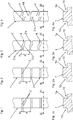
- Fig. 1 to Fig. 5 show different embodiments of profile bands 1 for a tread for a pneumatic vehicle tire in radial design, especially for passenger cars, vans and the like.
- executed pneumatic vehicle tires have treads that comprise at least one profile strip according to the invention carried out, but in particular predominantly or exclusively consist of profile strips designed according to the invention. Tread with inventively designed profile bands, however, may also have differently executed profile bands or profile block rows.
- the tread on between three and five executed according to the invention profile strips.
- Fig. 6 shows a preferred embodiment of the invention with five profile bands.
- FIGS. 1 to 5 show variants of profile strips 1, which in the circumferential direction on both sides have profile band edges 1a, which limit circumferential grooves 10.
- the circumferential grooves 10 are shown as straight grooves, but can also extend in the circumferential direction in a wave or zigzag shape, depending on the course of the profile band edges 1a.
- An essential feature of the invention is the structuring of the profile strips 1 with pairs and parallel to each other arranged incisions 2, 2 ', 2 "
- Distance a of the incision pairs, which at the ends of the incisions 2, 2 ', 2 "on a profile band edge 1a and between the two facing incisions 2, 2', 2" of two circumferentially adjoining incision pairs 2, 2 ', 2 " is determined, is between 25 mm and 35 mm and therefore corresponds to the usual circumferential extent of profile blocks in profile block rows.
- the mutual normal distance b of the paired incisions 2, 2 ', 2 substantially corresponds to the width of the profiled element bridge 3 between the incisions 2, 2', 2" and is between 5 mm and 10 mm.
- the distance b thus corresponds to the usual width of transverse grooves in profile block rows.
- the distance b remains substantially constant over the extent or the course of the paired incisions 2, 2 ', 2 "The incisions 2, 2', 2" themselves have a width in the order of 0.4 mm to 0.8 mm, in particular about 0.6 mm.
- the depth of the cuts 2, 2 ', 2 “corresponds to the intended tread depth, which is usually 8 mm, or is up to 5 mm, in particular up to 3 mm, less than the tread depth.
- the paired incisions 2 run straight in the tread transverse direction and traverse the profile band 1 Fig. 2 the embodiment shown corresponds to the course of the incisions 2 that of in Fig. 1 shown embodiment.
- the profile band 1 is provided on the profile band flanks 1a between the paired incisions 2 with indentations or pockets 4, so that the extension of the profile element bridges 3 in tread transverse direction is less than the width of the profile band 1 at this point.
- the pockets 4 extend between 1 mm and 3 mm in the profile band 1 and extend in the radial direction at most up to the tread depth or the depth of the circumferential grooves 10th
- Fig. 3 shows a variant in which the paired incisions 2 'the profiled strip edges 1a adjacent initially each running in the tread transverse direction incision sections 2'a have, which via incision sections 2'b, which extend at an acute angle to the tread transverse direction, interconnected are and are offset from each other in the circumferential direction.
- the transition areas between the individual cut-in sections 2'a and 2'b are rounded.
- the cut-in portions 2'b, with or without the subsequent rounded transitions, may have a depth which either corresponds to the depth of the cut-in portions 2'a or is somewhat smaller, in particular by up to 2 mm.
- connection grooves with a depth of a few tenths of a millimeter up to 1 mm may be provided, which merely have a decorative function.
- FIG. 3 embodiment shown are also analogous to the embodiment according to Fig. 2 Pockets 4 provided.
- paired incisions 2 are provided in the profile band 1.
- the paired incisions 2" terminate in the profile band center and run opposite the tread transverse direction at an acute angle which does not exceed 45 °.
- the incisions 2 have at their ends bent short sections 2" c, which are preferably made very shallow and in particular have a depth of a few tenths of a millimeter up to 1 mm.
- pockets 4 are provided.
- Fig. 5 shows an embodiment which is a variant of in Fig. 3 shown embodiment.
- the paired incisions 2 'therefore have incision sections 2'a and 2'b.
- the profile band flanks are 1a, as it is Fig. 5a shows, chamfered directly to the profile surface in a known manner, so that they have short inclined surfaces 5.
- the paired sipes 2, 2 ', 2 "replace the transverse grooves usually provided in profile block rows between the tread blocks
- the paired sipes 2, 2', 2" effect a distribution of the bending movements of the tread circumferentially during the unwinding of the tread Tire from a "joint” - in transverse grooves - on two “joints".
- the excitation frequency is on the order of 800 Hz.
- a pneumatic vehicle tire which is designed according to the invention, is significantly quieter than a tire with a block profile with transverse grooves.
- Fig. 1b shows schematically the deformation of a pair of cuts during the rolling of the tire just before entering or shortly after exiting the lat.
- Fig. 6 shows a partial development of a variant of a running according to the invention profiled tread.
- the tread shown has five circumferentially encircling tread bands 11, 11 'and 11 "along the tire equator, which is indicated by the line AA, runs the tread band 11, which with two rows of paired incisions 12 which offset in the circumferential direction against each other
- the design of the recess pairs with pockets 4 is essentially analogous to Fig. 4 with the difference that the cuts 12 have no shallow end portions.
- the incisions 12 are all parallel to each other and are inclined with respect to the tread transverse direction at a small acute angle of the order of 3 ° to 10 °.
- the profile band 11 is formed by two wide, circumferentially straight circumferential grooves 10 of the profile bands 11' separated, which in turn are separated by further, straight and circumferentially circumferential grooves 10 of the shoulder-side profile strips 11 "
- the incisions 12 ' form two rows of circumferentially offset pairs of incisions according to the invention.
- Connecting grooves 15 whose width corresponds to the incision width and which have a very small depth of a few tenths of a millimeter to 1 mm and extend in the circumferential direction, connect the notches 12 '.
Landscapes
- Engineering & Computer Science (AREA)
- Mechanical Engineering (AREA)
- Tires In General (AREA)
Abstract
Description
- Die Erfindung betrifft einen Fahrzeugluftreifen mit einem Laufstreifen mit in Umfangsrichtung umlaufenden und von Quernuten freien Profilbändern.
- Es ist üblich, Fahrzeugluftreifen mit profilierten Laufstreifen zu versehen, die sich ausschließlich aus Profilblockreihen oder Profilbändern zusammensetzen oder die eine Kombination von Profilblockreihen mit Profilbändern aufweisen. Unter Profilband wird ein in Umfangsrichtung umlaufender, meist durch Umfangsnuten begrenzter Abschnitt im Laufstreifen verstanden, welcher keine ihn durchquerenden Quernuten aufweist. Sowohl Profilbänder als auch Profilblockreihen können, je nach Einsatzweck des Reifens, mit Einschnitten, die üblicherweise eine Breite von 0,4 mm bis 0,8 mm aufweisen, versehen sein. Querrillen und Einschnitte haben hauptsächlich die Aufgaben, eine Entwässerung des Profils zu unterstützen, um Aquaplaning zu verhindern sowie die Traktion des Reifens auf nassem und trockenem Untergrund sicherzustellen und den Rollwiderstand zu senken.
- Aus der
EP 0 540 340 A2 ist ein Fahrzeugluftreifen bekannt, dessen Laufstreifen sich aus einer Anzahl von Profilblockreihen zusammensetzt. Die Blöcke in den Profilblockreihen sind voneinander durch Querrillen getrennt und weisen jeweils paarweise in Laufstreifenquerrichtung verlaufende Einschnitte auf, welche an ihren radial inneren Enden lokal verbreitert sind, um beim Entformen des Reifens nach der Vulkanisation das Entstehen von Einrissen am Boden der Einschnitte zu verhindern. Aus derEP 1 920 951 A1 ist ebenfalls ein Reifen bekannt, welcher ein Laufstreifenprofil mit Blockreihen aufweist. Die Blöcke sind jeweils mit zwei Paaren von in Laufstreifenquerrichtung verlaufenden Einschnitten versehen, um die Griffeigenschaften zu verbessern. - Wie bereits erwähnt sind die Querrillen in Laufstreifen von Reifen vor allem für gute Nässeeigenschaften und einen geringen Rollwiderstand von Bedeutung, stellen jedoch eine deutlich wahrnehmbare Geräuschquelle im Abrollgeräusch des Reifens dar.
- Der Erfindung liegt nun die Aufgabe zugrunde, bei einem Reifen der eingangs genannten Art das Abrollgeräusch zu verbessern bzw. zu verringern, aber gute Nässeeigenschaften zu erhalten und beim Abrollen eine derartige Verformung des Laufstreifens zu ermöglichen, dass ein geringer Rollwiderstand gewährleistet ist.
- Gelöst wird die gestellte Aufgabe erfindungsgemäß dadurch, dass die Profilbänder anstelle von Quernuten paarweise angeordnete, parallel zueinander und im Wesentlichen in Laufstreifenquerrichtung verlaufende Einschnitte mit einer Breite von 0,4 mm bis 0,8 mm aufweisen.
- Insbesondere beträgt der gegenseitige Abstand der Einschnittpaare, an den Enden der Einschnitte als Abstand zwischen den einander zugewandten Einschnitten der beiden Einschnittpaare ermittelt, zwischen 25 mm und 35 mm und der Normalabstand der Einschnitte eines Einschnittpaares zwischen 5 mm und 10 mm.
- Ein gemäß der Erfindung ausgeführter Fahrzeugluftreifen weist daher ein Laufstreifenprofil mit Profilbändern auf, welche mit paarweise angeordneten Einschnitten versehen sind, deren Anordnung an die Anordnung von üblichen Quernuten in Profilblockreihen angeglichen ist. Die "Profilmechanik" entspricht daher im Wesentlichen jener eines herkömmlichen Laufstreifenprofils mit Quernuten. Dadurch entsprechen vor allem die Trockenfahreigenschaften erfindungsgemäßer Laufstreifen zumindest jenen eines herkömmlich gestalteten Laufstreifens. Der Ersatz der Quernuten durch Einschnittpaare bewirkt eine Aufteilung der beim Abrollen stattfindenden Biegebewegung in Umfangsrichtung von einer Gelenksstelle, wie es bei einer Quernut der Fall ist, auf zwei Gelenksstellen. Für das Geräusch bedeutet dies eine Verschiebung der Anregungsfrequenz hin zu höheren Frequenzen. Mit einem Reifen mit beispielsweise 70 Quernuten am Reifenumfang ergibt sich bei einer Fahrgeschwindigkeit von 80km/h eine Anregungsfrequenz in der Größenordnung von 800 Hz. Der Ersatz der Quernuten durch Einschnittpaare reduziert die Anregung bei 800 Hz und erzeugt eine zusätzliche Anregung, die deutlich oberhalb von 800 Hz liegt. Da Frequenzen über 1000 Hz bei PKW-Fahrzeugluftreifen schlecht abgestrahlt werden, schlechter als Frequenzen unter 1000 Hz, ist ein Fahrzeugluftreifen mit erfindungsgemäß ausgeführten Profilbändern anstelle von Profilblockreihen deutlich leiser.
- Profilbänder, die weitgehend nur durch Einschnitte strukturiert sind, erzeugen ferner einen wesentlich geringeren Kontaktdruck als Profilblockreihen, wodurch das Gummimaterial im Laufstreifen geringer komprimiert wird. Der gegenseitige Abstützeffekt der Einschnittwände kommt der Verringerung der Kompression noch entgegen. Diese Effekte sind besonders positiv für einen geringeren Rollwiderstand. Das Gummimaterial zwischen den paarweise angeordneten Einschnitten stabilisiert den Laufstreifen, wenn dieser über die Reifenbreite Knick- und Biegebeanspruchungen ausgesetzt wird. Diese Stabilisierung bietet Vorteile beim Laufstreifenabrieb und bei den Trockenfahreigenschaften.
- Bei einer bevorzugten Ausführungsform der Erfindung sind die paarweise angeordneten Einschnitte im Profilband in zwei Einschnittreihen angeordnet, die vorzugsweise in Umfangsrichtung gegeneinander versetzt sind. Mit derart angeordneten Einschnittpaaren kann gezielt Einfluss auf den Kontaktdruck sowie die Stabilität des Profilbandes genommen werden. Eine alternative Ausführungsvariante, bei der die paarweise angeordneten Einschnitte das Profilband durchqueren, gestattet ebenfalls eine entsprechende Einflussnahme.
- Bei Ausführungsformen, bei welchen die Einschnittpaare in zwei Einschnittreihen im Profilband angeordnet sind, kann vorgesehen sein, jeweils zwei in Umfangsrichtung benachbarte Einschnittpaare durch Verbindungsrillen miteinander zu verbinden, welche gleich breit wie die Einschnitte ausgeführt sind, jedoch eine geringere Tiefe aufweisen, als die Einschnitte, insbesondere beträgt ihre Tiefe einige Zehntelmillimeter bis zu 1 mm. Derartig ausgeführte Verbindungsrillen unterstützen bei neuem Reifen die Entwässerung, haben jedoch auch eine Dekorwirkung. Diese Verbindungsrillen können auch in Umfangsrichtung verlaufen.
- Für das Abrollgeräusch des Reifens ist es ferner von Vorteil, wenn die paarweise angeordneten Einschnitte bzw. ihre Abschnitte unter einem spitzen Winkel von bis zu 45° zur Laufstreifenquerrichtung verlaufen.
- Durch die Erfindung wird eine Verteilung der Spreizung des Gummimaterials beim Abrollen des Reifens auf die beiden Einschnitte bewirkt, was eine geringere Kerbwirkung und einen geringeren Rollwiderstand zu Folge hat. Es ist daher vorteilhaft, wenn die paarweise angeordneten Einschnitte eine gewisse Mindesttiefe aufweisen. Ihre Tiefe sollte entweder der Profiltiefe entsprechen oder um bis zu 5 mm, insbesondere um bis zu 3 mm, geringer sein als die Profiltiefe.
- Bei einer weiteren, vorteilhaften Ausführungsform der Erfindung ist das Profilband zwischen paarweise angeordneten Einschnitten zumindest einseitig jeweils mit Einbuchtungen oder Taschen versehen. Auf diese Weise ist die Profilelementbrücke zwischen den paarweise angeordneten Einschnitten gegenüber der an dieser Stelle vorliegenden Profilbandbreite in Querrichtung etwas verkürzt. Durch die Taschen werden an den Profilbändern in Querrichtung Kantenabschnitte zur Verfügung gestellt, welche die Traktion des Reifens, beispielsweise in Schneematsch oder Schnee, unterstützen. Die Taschen reichen in einem Ausmaß von 1 mm bis 3 mm in das Profilband hinein und erstrecken sich in radialer Richtung höchstens bis auf die Profiltiefe bzw. die Tiefe der das jeweilige Profilband begrenzende(n) Umfangsnut bzw. Umfangsnuten.
- Weitere Merkmale, Vorteile und Einzelheiten der Erfindung werden nun anhand der Zeichnung, die schematisch einige Ausführungsbeispiele darstellt, näher beschrieben. Dabei zeigen
-
Fig. 1 bis Fig. 5 Draufsichten auf in Umfangsrichtung umlaufende Laufstreifenprofilbänder mit unterschiedlichen Ausführungsvarianten der Erfindung, -
Fig. 1a bis Fig. 5a Schnittdarstellungen der Profilbänder ausFig. 1 bis Fig. 5 , jeweils entlang der Linien S-S, -
Fig. 1b einen Schnitt entlang der Linie Ib-Ib derFig. 1 und -
Fig. 6 eine Teilabwicklung eines Laufstreifenprofils mit gemäß der Erfindung ausgeführten Profilbändern. -
Fig. 1 bis Fig. 5 zeigen unterschiedliche Ausführungsvarianten von Profilbändern 1 für einen Laufstreifen für einen Fahrzeugluftreifen in Radialbauart, insbesondere für Personenkraftwagen, Vans und dergleichen. Erfindungsgemäß ausgeführte Fahrzeugluftreifen weisen Laufstreifen auf, die zumindest ein erfindungsgemäß ausgeführtes Profilband umfassen, insbesondere jedoch überwiegend oder ausschließlich aus erfindungsgemäß ausgeführten Profilbändern bestehen. Laufstreifen mit erfindungsgemäß gestalteten Profilbändern können jedoch auch anders ausgeführte Profilbänder oder auch Profilblockreihen aufweisen. Bei einer bevorzugten Ausführungsform der Erfindung weist der Laufstreifen zwischen drei und fünf erfindungsgemäß ausgeführte Profilbänder auf.Fig. 6 zeigt eine bevorzugte Ausführungsform der Erfindung mit fünf Profilbändern. - Die
Figuren 1 bis 5 zeigen Ausführungsvarianten von Profilbändern 1, welche in Umfangsrichtung beidseitig Profilbandflanken 1a aufweisen, welche Umfangsnuten 10 begrenzen. Die Umfangsnuten 10 sind als gerade verlaufende Nuten dargestellt, können jedoch in Umfangsrichtung auch in Wellenform oder Zickzackform verlaufen, je nach dem Verlauf der Profilbandflanken 1a. - Ein wesentliches Merkmal der Erfindung ist die Strukturierung der Profilbänder 1 mit paarweise und parallel zueinander angeordneten Einschnitten 2, 2', 2". Der gegenseitige
- Abstand a der Einschnittpaare, welcher bei den Enden der Einschnitte 2, 2', 2" an einer Profilbandflanke 1a und zwischen den beiden einander zugewandten Einschnitten 2, 2', 2" von zwei in Umfangsrichtung aneinander anschließenden Einschnittpaaren 2, 2', 2" ermittelt wird, beträgt zwischen 25 mm und 35 mm und entspricht daher der üblichen Umfangserstreckung von Profilblöcken in Profilblockreihen.
- Der gegenseitige Normalabstand b der paarweise angeordneten Einschnitte 2, 2', 2" entspricht im Wesentlichen der Breite der Profilelementbrücke 3 zwischen den Einschnitten 2, 2', 2" und beträgt zwischen 5 mm und 10 mm. Der Abstand b entspricht somit der üblichen Breite von Quernuten in Profilblockreihen. Über die Erstreckung bzw. den Verlauf der paarweise angeordneten Einschnitte 2, 2', 2" bleibt der Abstand b weitgehend konstant. Die Einschnitte 2, 2', 2" selbst weisen eine Breite in der Größenordnung von 0,4 mm bis 0,8 mm, insbesondere etwa 0,6 mm, auf. Die Tiefe der Einschnitte 2, 2', 2" entspricht der vorgesehenen Profiltiefe, die üblicherweise 8 mm beträgt, oder ist um bis zu 5 mm, insbesondere bis zu 3 mm, geringer als die Profiltiefe.
- Bei der in
Fig. 1 gezeigten Ausführungsform verlaufen die paarweise angeordneten Einschnitte 2 gerade in Laufstreifenquerrichtung und durchqueren das Profilband 1. Bei der inFig. 2 gezeigten Ausführungsvariante entspricht der Verlauf der Einschnitte 2 jenem der inFig. 1 gezeigten Ausführungsform. Das Profilband 1 ist jedoch an den Profilbandflanken 1a zwischen den paarweise angeordneten Einschnitten 2 mit Einbuchtungen bzw. Taschen 4 versehen, sodass die Erstreckung der Profilelementbrücken 3 in Laufstreifenquerrichtung geringer ist als die Breite des Profilbandes 1 an dieser Stelle. Die Taschen 4 reichen zwischen 1 mm und 3 mm in das Profilband 1 hinein und erstrecken sich in radialer Richtung höchstens bis auf die Profiltiefe bzw. die Tiefe der Umfangsnuten 10. -
Fig. 3 zeigt eine Ausführungsvariante, bei der die paarweise angeordneten Einschnitte 2' den Profilbandflanken 1a benachbart vorerst jeweils in Laufstreifenquerrichtung verlaufende Einschnittabschnitte 2'a aufweisen, welche über Einschnittabschnitte 2'b, die unter einem spitzen Winkel zur Laufstreifenquerrichtung verlaufen, miteinander verbunden sind und derart in Umfangsrichtung gegeneinander versetzt sind. Die Übergangsbereiche zwischen den einzelnen Einschnittabschnitten 2'a und 2'b sind gerundet ausgeführt. Die Einschnittabschnitte 2'b - mit oder ohne die anschließenden gerundeten Übergänge - können eine Tiefe aufweisen, die entweder der Tiefe der Einschnittabschnitte 2'a entspricht oder etwas, insbesondere um bis zu 2 mm, geringer ist. Anstelle der Einschnittabschnitte 2'b können sehr seichte Verbindungsrillen mit einer Tiefe von wenigen Zehntelmillimetern bis zu 1 mm vorgesehen sein, die lediglich eine dekorierende Funktion haben. Bei der inFig. 3 gezeigten Ausführungsvariante sind ferner analog zur Ausführungsform gemäßFig. 2 Taschen 4 vorgesehen. - Bei der in
Fig. 4 gezeigten Ausführungsvariante sind im Profilband 1 zwei in Umfangsrichtung versetzte "Reihen" von paarweise angeordneten Einschnitten 2" vorgesehen. Die paarweise angeordneten Einschnitte 2" enden in der Profilbandmitte und verlaufen gegenüber der Laufstreifenquerrichtung unter einem spitzen Winkel, welcher 45° nicht übersteigt. Die Einschnitte 2" weisen an ihren Enden abgebogene kurze Abschnitte 2"c auf, die vorzugsweise sehr seicht ausgeführt sind und insbesondere eine Tiefe von einigen Zehntelmillimetern bis zu 1 mm aufweisen. Auch bei der inFig. 4 gezeigten Ausführungsvariante sind Taschen 4 vorgesehen. -
Fig. 5 zeigt eine Ausführungsform, die eine Variante der inFig. 3 gezeigten Ausführungsform ist. Die paarweise angeordneten Einschnitte 2' weisen daher Einschnittabschnitte 2'a und 2'b auf. Zusätzlich sind die Profilbandflanken 1a, wie esFig. 5a zeigt, unmittelbar an der Profiloberfläche in bekannter Weise angefast, sodass sie kurze Schrägflächen 5 aufweisen. - Wie bereits erwähnt ersetzen die paarweise angeordneten Einschnitte 2, 2', 2" die üblicherweise in Profilblockreihen zwischen den Profilblöcken vorgesehenen Quernuten. Die paarweise angeordneten Einschnitte 2, 2', 2" bewirken quasi eine Aufteilung der Biegebewegungen des Laufstreifens in Umfangsrichtung während des Abrollens des Reifens von einer "Gelenkstelle" - bei Quernuten - auf zwei "Gelenkstellen". Für das Abrollgeräusch bedeutet dies eine Verschiebung der Anregungsfrequenz hin zu höheren Frequenzen. So ist beispielsweise bei einem Reifen mit einem Laufstreifen mit einem Blockprofil mit etwa 70 Querrillen über den Reifenumfang bei einer Fahrgeschwindigkeit von 80 km/h die Anregungsfrequenz in der Größenordnung von 800 Hz. Werden Blockreihen im Laufstreifen durch Profilbänder mit Einschnittpaaren ersetzt, wird die Anregung bei 800 Hz reduziert und eine zusätzliche Anregung in einem Frequenzbereich deutlich oberhalb von 800 Hz erzeugt. Da Frequenzen oberhalb von 1000 Hz bei PKW-Fahrzeugluftreifen meist schlecht abgestrahlt werden, ist ein Fahrzeugluftreifen, welcher gemäß der Erfindung ausgeführt ist, deutlich leiser als ein Reifen mit einem Blockprofil mit Quernuten.
Fig. 1b zeigt schematisch die Verformung eines Einschnittpaares während des Abrollens des Reifens kurz vor dem Eintritt in den oder kurz nach dem Austritt aus dem Latsch. WieFig. 1b zeigt, verteilt sich die Spreizung des Gummimaterials auf die beiden Einschnitte 2, was beim Abrollen des Reifens eine geringere Kerbwirkung und einen geringeren Rollwiderstand zur Folge hat, da sich durch das bereits erwähnte "Doppelgelenk" das Gummimaterial weniger verformt als dies bei Reifen mit breiten Quernuten im Laufstreifen der Fall ist. -
Fig. 6 zeigt eine Teilabwicklung einer Ausführungsvariante eines gemäß der Erfindung ausgeführten profilierten Laufstreifens. Der gezeigte Laufstreifen weist fünf in Umfangsrichtung umlaufende Profilbänder 11, 11' und 11" auf. Entlang des Reifenäquators, welcher durch die Linie A-A angedeutet ist, verläuft das Laufstreifenband 11, welches mit zwei Reihen von paarweise angeordneten Einschnitten 12, die in Umfangsrichtung gegeneinander versetzt sind, versehen ist. Die Ausführung der Einschnittpaare mit Taschen 4 ist im Wesentlichen analog zuFig. 4 mit dem Unterschied, dass die Einschnitte 12 keine seichten Endabschnitte aufweisen. Die Einschnitte 12 verlaufen sämtlich parallel zueinander und sind gegenüber der Laufstreifenquerrichtung unter einem kleinen spitzen Winkel in der Größenordnung von 3° bis 10 °geneigt. Eine schmale (ca. 1 mm breite), seichte (ca. 1 mm tiefe) Dekorrille 14' verläuft in Umfangsrichtung und mittig durch das Profilband 11. Das Profilband 11 ist durch zwei breite, in Umfangsrichtung gerade umlaufende Umfangsnuten 10 von den Profilbändern 11' getrennt, die ihrerseits durch weitere, gerade und in Umfangsrichtung umlaufende Umfangsnuten 10 von den schulterseitigen Profilbändern 11" getrennt sind. In den - Profilbändern 11' sind paarweise angeordnete Einschnitte 12' angeordnet, die vom Konzept her der in
Fig. 4 gezeigten Ausführungsform entsprechen. Die Einschnitte 12' bilden zwei Reihen von in Umfangsrichtung gegeneinander versetzten Einschnittpaaren gemäß der Erfindung. Verbindungsrillen 15, deren Breite der Einschnittbreite entspricht und die eine sehr geringe Tiefe von einigen Zehntelmillimetern bis 1 mm aufweisen sowie in Umfangsrichtung verlaufen, verbinden die Einschnitte 12'. Auch in den Profilbändern 11' befinden sich an den Profilbandflanken zwischen den paarweise zusammengehörenden Einschnitten 12' die beschriebenen Taschen 4. - In den schulterseitigen Profilbändern 11" befinden sich paarweise angeordnete Einschnitte 12" mit einem Einschnittkonzept, welches im Wesentlichen der in
Fig. 3 gezeigten grundsätzlichen Ausführungsform entspricht. Die paarweise angeordneten Einschnitte 12" münden bei dieser Ausführungsvariante jedoch nicht in die Umfangsnut 10, es verbleibt jeweils zwischen den Einschnittenden und der Umfangsnut 10 ein schmaler Steg 7, wodurch das Abrollgeräusch günstig beeinflusst wird. - Die gemäß der Erfindung im Laufstreifen vorgesehenen und Quernuten ersetzenden Einschnitte 2, 2', 2", 12, 12', 12" werden ferner grundsätzlich derart angeordnet, dass sie zur Laufstreifenquerrichtung unter einem Winkel von höchstens 45° verlaufen.
-
- 1 ....................
- Profilband
- 1a....................
- Profilbandflanken
- 2, 2', 2" ..........
- Einschnitt
- 2'a, 2'b............
- Einschnittabschnitt
- 2"c..................
- Abschnitt
- 3......................
- Profilelementbrücke
- 4......................
- Tasche
- 5......................
- Schrägfläche
- 7......................
- Steg
- 10....................
- Umfangsnut
- 11, 11', 11" ....
- Profilband
- 12, 12', 12" ....
- Einschnitt
- 14, 14'.............
- Dekorrille
- 15....................
- Verbindungsrille
- A-A.................
- Reifenäquator
- a......................
- Abstand
- b......................
- Abstand
Claims (13)
- Fahrzeugluftreifen mit einem Laufstreifen mit in Umfangsrichtung umlaufenden und von Quernuten freien Profilbändern (1, 11, 11', 11"),
dadurch gekennzeichnet,
dass die Profilbänder (1, 11, 11', 11") anstelle von Quernuten paarweise angeordnete, parallel zueinander und im Wesentlichen in Laufstreifenquerrichtung verlaufende Einschnitte (2, 2', 2", 12, 12', 12") mit einer Breite von 0,4 mm bis 0,8 mm aufweisen. - Fahrzeugluftreifen nach Anspruch 1, dadurch gekennzeichnet, dass der gegenseitige Abstand (a) der Einschnittpaare, an den Enden der Einschnitte (2, 2', 2", 12, 12', 12") als Abstand der einander zugewandten Einschnitte (2, 2', 2", 12, 12', 12") der beiden Einschnittpaare ermittelt, zwischen 25 mm und 35 mm beträgt.
- Fahrzeugluftreifen nach Anspruch 1 oder 2, dadurch gekennzeichnet, dass der Normalabstand (b) der Einschnitte (2, 2', 2", 12, 12', 12") eines Einschnittpaares zwischen 5 mm und 10 mm beträgt.
- Fahrzeugluftreifen nach einem der Ansprüche 1 bis 3, dadurch gekennzeichnet, dass die paarweise angeordneten Einschnitte (2", 12') im Profilband (1, 11') in zwei Einschnittreihen angeordnet sind, die vorzugsweise in Umfangsrichtung gegeneinander versetzt sind.
- Fahrzeugluftreifen nach Anspruch 4, dadurch gekennzeichnet, dass jeweils zwei in Umfangsrichtung benachbarte Einschnittpaare aus den beiden Einschnittreihen miteinander durch Verbindungsrillen (15) verbunden sind, welche gleich breit wie die Einschnitte (12') ausgeführt sind und eine geringere Tiefe aufweisen als die Einschnitte (12').
- Fahrzeugluftreifen nach Anspruch 5, dadurch gekennzeichnet, dass die Verbindungsrillen (15) eine Tiefe von einigen Zehntelmillimetern bis zu 1 mm aufweisen.
- Fahrzeugluftreifen nach einem der Ansprüche 1 bis 3, dadurch gekennzeichnet, dass die paarweise angeordneten Einschnitte (2, 2') das Profilband (1) durchqueren.
- Fahrzeugluftreifen nach einem der Ansprüche 1 bis 3 oder 7, dadurch gekennzeichnet, dass die paarweise angeordneten Einschnitte (2'), den Profilbandflanken (1a) benachbart, Einschnittabschnitte (2'a) aufweisen, die in Umfangsrichtung gegeneinander versetzt sind und über mittige Einschnittabschnitte (2'b) verbunden sind, die unter einem größeren spitzen Winkel zur Laufstreifenquerrichtung verlaufen als die Einschnittabschnitte (2'a) an den Profilbandflanken (1a).
- Fahrzeugluftreifen nach Anspruch 8, dadurch gekennzeichnet, dass die mittigen Einschnittabschnitte (2'b) eine Tiefe aufweisen, die der Tiefe der an sie anschließenden Einschnittabschnitte (2'a) entspricht oder um bis zu 2 mm geringer ist als die Tiefe der an sie anschließenden Einschnittabschnitte (2'a).
- Fahrzeugluftreifen nach einem der Ansprüche 1 bis 9, dadurch gekennzeichnet, dass die paarweise angeordneten Einschnitte (2, 2', 2", 12, 12', 12") unter einem spitzen Winkel von bis zu 45° zur Laufstreifenquerrichtung verlaufen.
- Fahrzeugluftreifen nach einem der Ansprüche 1 bis 10, dadurch gekennzeichnet, dass die paarweise angeordneten Einschnitte (2, 2', 2", 12, 12', 12") eine Tiefe aufweisen, die der Profiltiefe entspricht oder bis zu 5 mm, insbesondere bis zu 3 mm, geringer ist als die Profiltiefe.
- Fahrzeugluftreifen nach einem der Ansprüche 1 bis 11, dadurch gekennzeichnet, dass das Profilband (1) zwischen paarweise angeordneten Einschnitten (2, 2', 2", 12, 12', 12") zumindest einseitig mit Einbuchtungen oder Taschen (4) versehen ist.
- Fahrzeugluftreifen nach Anspruch 12, dadurch gekennzeichnet, dass die Taschen (4) zwischen 1 mm und 3 mm in das Profilband (1, 11, 11') hineinragen und sich in radialer Richtung höchstens bis auf die Profiltiefe erstrecken.
Priority Applications (1)
| Application Number | Priority Date | Filing Date | Title |
|---|---|---|---|
| PL12153973T PL2505389T3 (pl) | 2011-03-29 | 2012-02-06 | Opona pneumatyczna do pojazdu |
Applications Claiming Priority (1)
| Application Number | Priority Date | Filing Date | Title |
|---|---|---|---|
| DE102011001634A DE102011001634A1 (de) | 2011-03-29 | 2011-03-29 | Fahrzeugluftreifen |
Publications (2)
| Publication Number | Publication Date |
|---|---|
| EP2505389A1 true EP2505389A1 (de) | 2012-10-03 |
| EP2505389B1 EP2505389B1 (de) | 2015-04-29 |
Family
ID=45560798
Family Applications (1)
| Application Number | Title | Priority Date | Filing Date |
|---|---|---|---|
| EP20120153973 Not-in-force EP2505389B1 (de) | 2011-03-29 | 2012-02-06 | Fahrzeugluftreifen |
Country Status (3)
| Country | Link |
|---|---|
| EP (1) | EP2505389B1 (de) |
| DE (1) | DE102011001634A1 (de) |
| PL (1) | PL2505389T3 (de) |
Citations (9)
| Publication number | Priority date | Publication date | Assignee | Title |
|---|---|---|---|---|
| US3550665A (en) * | 1967-09-18 | 1970-12-29 | Gen Etablissements Michelin Ra | Tire cover |
| US4449560A (en) * | 1981-05-13 | 1984-05-22 | Bridgestone Tire Company Limited | Heavy duty pneumatic tire |
| GB2160829A (en) * | 1984-05-15 | 1986-01-02 | Sumitomo Rubber Ind | Multi-siped tire for low noise running |
| EP0178859A2 (de) * | 1984-10-13 | 1986-04-23 | Sumitomo Rubber Industries Limited | Radialreifen für Lastkraftwagen |
| US5109901A (en) * | 1987-05-11 | 1992-05-05 | Bridgestone Corporation | Pneumatic radial tires having a tread including isolated sipes |
| EP0540340A2 (de) | 1991-11-01 | 1993-05-05 | Bridgestone Corporation | Luftreifen, Form und Verfahren zur Herstellung |
| EP1864830A2 (de) * | 2006-06-07 | 2007-12-12 | The Yokohama Rubber Co., Ltd. | Luftreifen |
| EP1920951A1 (de) | 2006-11-08 | 2008-05-14 | Bridgestone Corporation | Luftreifen mit Lamellen die am Lamellengrund verdickt sind |
| WO2011131381A1 (de) * | 2010-04-19 | 2011-10-27 | Continental Reifen Deutschland Gmbh | Fahrzeugluftreifen |
-
2011
- 2011-03-29 DE DE102011001634A patent/DE102011001634A1/de not_active Withdrawn
-
2012
- 2012-02-06 EP EP20120153973 patent/EP2505389B1/de not_active Not-in-force
- 2012-02-06 PL PL12153973T patent/PL2505389T3/pl unknown
Patent Citations (9)
| Publication number | Priority date | Publication date | Assignee | Title |
|---|---|---|---|---|
| US3550665A (en) * | 1967-09-18 | 1970-12-29 | Gen Etablissements Michelin Ra | Tire cover |
| US4449560A (en) * | 1981-05-13 | 1984-05-22 | Bridgestone Tire Company Limited | Heavy duty pneumatic tire |
| GB2160829A (en) * | 1984-05-15 | 1986-01-02 | Sumitomo Rubber Ind | Multi-siped tire for low noise running |
| EP0178859A2 (de) * | 1984-10-13 | 1986-04-23 | Sumitomo Rubber Industries Limited | Radialreifen für Lastkraftwagen |
| US5109901A (en) * | 1987-05-11 | 1992-05-05 | Bridgestone Corporation | Pneumatic radial tires having a tread including isolated sipes |
| EP0540340A2 (de) | 1991-11-01 | 1993-05-05 | Bridgestone Corporation | Luftreifen, Form und Verfahren zur Herstellung |
| EP1864830A2 (de) * | 2006-06-07 | 2007-12-12 | The Yokohama Rubber Co., Ltd. | Luftreifen |
| EP1920951A1 (de) | 2006-11-08 | 2008-05-14 | Bridgestone Corporation | Luftreifen mit Lamellen die am Lamellengrund verdickt sind |
| WO2011131381A1 (de) * | 2010-04-19 | 2011-10-27 | Continental Reifen Deutschland Gmbh | Fahrzeugluftreifen |
Also Published As
| Publication number | Publication date |
|---|---|
| PL2505389T3 (pl) | 2015-09-30 |
| EP2505389B1 (de) | 2015-04-29 |
| DE102011001634A1 (de) | 2012-10-04 |
Similar Documents
| Publication | Publication Date | Title |
|---|---|---|
| EP2965925B1 (de) | Fahrzeugluftreifen | |
| DE102005042569A1 (de) | Fahrzeugluftreifen | |
| DE102015224291A1 (de) | Fahrzeugluftreifen | |
| DE102019213044A1 (de) | Fahrzeugluftreifen | |
| WO2013064300A1 (de) | Fahrzeugluftreifen | |
| EP2560830A1 (de) | Fahrzeugluftreifen | |
| EP3441241B1 (de) | Fahrzeugluftreifen | |
| EP4244079B1 (de) | Fahrzeugluftreifen | |
| EP3446892B1 (de) | Fahrzeugluftreifen | |
| EP3659825A1 (de) | Fahrzeugluftreifen | |
| EP4171972B1 (de) | Fahrzeugluftreifen | |
| EP3551477B1 (de) | Fahrzeugluftreifen | |
| DE102015202615A1 (de) | Fahrzeugluftreifen | |
| EP4144542B1 (de) | Fahrzeugluftreifen | |
| EP4347276B1 (de) | Fahrzeugluftreifen | |
| EP2000329B1 (de) | Fahrzeugluftreifen | |
| DE102019214093A1 (de) | Fahrzeugluftreifen | |
| AT394002B (de) | Radialreifen fuer raeder von lkw-antriebsachsen | |
| EP2505389B1 (de) | Fahrzeugluftreifen | |
| WO2018103920A1 (de) | Fahrzeugluftreifen | |
| DE102018206902A1 (de) | Fahrzeugluftreifen | |
| EP2660081A1 (de) | Laufstreifenprofil eines Fahrzeugreifens | |
| WO2023274469A1 (de) | Fahrzeugluftreifen | |
| EP4385761B1 (de) | Fahrzeugluftreifen | |
| EP1535759B1 (de) | Fahrzeugluftreifen |
Legal Events
| Date | Code | Title | Description |
|---|---|---|---|
| PUAI | Public reference made under article 153(3) epc to a published international application that has entered the european phase |
Free format text: ORIGINAL CODE: 0009012 |
|
| AK | Designated contracting states |
Kind code of ref document: A1 Designated state(s): AL AT BE BG CH CY CZ DE DK EE ES FI FR GB GR HR HU IE IS IT LI LT LU LV MC MK MT NL NO PL PT RO RS SE SI SK SM TR |
|
| AX | Request for extension of the european patent |
Extension state: BA ME |
|
| 17P | Request for examination filed |
Effective date: 20130403 |
|
| 17Q | First examination report despatched |
Effective date: 20140226 |
|
| GRAP | Despatch of communication of intention to grant a patent |
Free format text: ORIGINAL CODE: EPIDOSNIGR1 |
|
| INTG | Intention to grant announced |
Effective date: 20141127 |
|
| GRAP | Despatch of communication of intention to grant a patent |
Free format text: ORIGINAL CODE: EPIDOSNIGR1 |
|
| GRAS | Grant fee paid |
Free format text: ORIGINAL CODE: EPIDOSNIGR3 |
|
| GRAA | (expected) grant |
Free format text: ORIGINAL CODE: 0009210 |
|
| INTG | Intention to grant announced |
Effective date: 20150312 |
|
| AK | Designated contracting states |
Kind code of ref document: B1 Designated state(s): AL AT BE BG CH CY CZ DE DK EE ES FI FR GB GR HR HU IE IS IT LI LT LU LV MC MK MT NL NO PL PT RO RS SE SI SK SM TR |
|
| REG | Reference to a national code |
Ref country code: GB Ref legal event code: FG4D Free format text: NOT ENGLISH |
|
| REG | Reference to a national code |
Ref country code: CH Ref legal event code: EP |
|
| REG | Reference to a national code |
Ref country code: AT Ref legal event code: REF Ref document number: 724216 Country of ref document: AT Kind code of ref document: T Effective date: 20150515 |
|
| REG | Reference to a national code |
Ref country code: IE Ref legal event code: FG4D Free format text: LANGUAGE OF EP DOCUMENT: GERMAN |
|
| REG | Reference to a national code |
Ref country code: DE Ref legal event code: R096 Ref document number: 502012002961 Country of ref document: DE Effective date: 20150611 |
|
| REG | Reference to a national code |
Ref country code: NL Ref legal event code: T3 |
|
| REG | Reference to a national code |
Ref country code: LT Ref legal event code: MG4D |
|
| REG | Reference to a national code |
Ref country code: PL Ref legal event code: T3 |
|
| PG25 | Lapsed in a contracting state [announced via postgrant information from national office to epo] |
Ref country code: FI Free format text: LAPSE BECAUSE OF FAILURE TO SUBMIT A TRANSLATION OF THE DESCRIPTION OR TO PAY THE FEE WITHIN THE PRESCRIBED TIME-LIMIT Effective date: 20150429 Ref country code: LT Free format text: LAPSE BECAUSE OF FAILURE TO SUBMIT A TRANSLATION OF THE DESCRIPTION OR TO PAY THE FEE WITHIN THE PRESCRIBED TIME-LIMIT Effective date: 20150429 Ref country code: HR Free format text: LAPSE BECAUSE OF FAILURE TO SUBMIT A TRANSLATION OF THE DESCRIPTION OR TO PAY THE FEE WITHIN THE PRESCRIBED TIME-LIMIT Effective date: 20150429 Ref country code: NO Free format text: LAPSE BECAUSE OF FAILURE TO SUBMIT A TRANSLATION OF THE DESCRIPTION OR TO PAY THE FEE WITHIN THE PRESCRIBED TIME-LIMIT Effective date: 20150729 Ref country code: ES Free format text: LAPSE BECAUSE OF FAILURE TO SUBMIT A TRANSLATION OF THE DESCRIPTION OR TO PAY THE FEE WITHIN THE PRESCRIBED TIME-LIMIT Effective date: 20150429 Ref country code: PT Free format text: LAPSE BECAUSE OF FAILURE TO SUBMIT A TRANSLATION OF THE DESCRIPTION OR TO PAY THE FEE WITHIN THE PRESCRIBED TIME-LIMIT Effective date: 20150831 |
|
| PG25 | Lapsed in a contracting state [announced via postgrant information from national office to epo] |
Ref country code: GR Free format text: LAPSE BECAUSE OF FAILURE TO SUBMIT A TRANSLATION OF THE DESCRIPTION OR TO PAY THE FEE WITHIN THE PRESCRIBED TIME-LIMIT Effective date: 20150730 Ref country code: IS Free format text: LAPSE BECAUSE OF FAILURE TO SUBMIT A TRANSLATION OF THE DESCRIPTION OR TO PAY THE FEE WITHIN THE PRESCRIBED TIME-LIMIT Effective date: 20150829 Ref country code: RS Free format text: LAPSE BECAUSE OF FAILURE TO SUBMIT A TRANSLATION OF THE DESCRIPTION OR TO PAY THE FEE WITHIN THE PRESCRIBED TIME-LIMIT Effective date: 20150429 Ref country code: LV Free format text: LAPSE BECAUSE OF FAILURE TO SUBMIT A TRANSLATION OF THE DESCRIPTION OR TO PAY THE FEE WITHIN THE PRESCRIBED TIME-LIMIT Effective date: 20150429 |
|
| PG25 | Lapsed in a contracting state [announced via postgrant information from national office to epo] |
Ref country code: DK Free format text: LAPSE BECAUSE OF FAILURE TO SUBMIT A TRANSLATION OF THE DESCRIPTION OR TO PAY THE FEE WITHIN THE PRESCRIBED TIME-LIMIT Effective date: 20150429 Ref country code: EE Free format text: LAPSE BECAUSE OF FAILURE TO SUBMIT A TRANSLATION OF THE DESCRIPTION OR TO PAY THE FEE WITHIN THE PRESCRIBED TIME-LIMIT Effective date: 20150429 |
|
| REG | Reference to a national code |
Ref country code: DE Ref legal event code: R097 Ref document number: 502012002961 Country of ref document: DE |
|
| REG | Reference to a national code |
Ref country code: FR Ref legal event code: PLFP Year of fee payment: 5 |
|
| PG25 | Lapsed in a contracting state [announced via postgrant information from national office to epo] |
Ref country code: CZ Free format text: LAPSE BECAUSE OF FAILURE TO SUBMIT A TRANSLATION OF THE DESCRIPTION OR TO PAY THE FEE WITHIN THE PRESCRIBED TIME-LIMIT Effective date: 20150429 Ref country code: SK Free format text: LAPSE BECAUSE OF FAILURE TO SUBMIT A TRANSLATION OF THE DESCRIPTION OR TO PAY THE FEE WITHIN THE PRESCRIBED TIME-LIMIT Effective date: 20150429 Ref country code: RO Free format text: LAPSE BECAUSE OF NON-PAYMENT OF DUE FEES Effective date: 20150429 |
|
| PLBE | No opposition filed within time limit |
Free format text: ORIGINAL CODE: 0009261 |
|
| STAA | Information on the status of an ep patent application or granted ep patent |
Free format text: STATUS: NO OPPOSITION FILED WITHIN TIME LIMIT |
|
| 26N | No opposition filed |
Effective date: 20160201 |
|
| PG25 | Lapsed in a contracting state [announced via postgrant information from national office to epo] |
Ref country code: BE Free format text: LAPSE BECAUSE OF NON-PAYMENT OF DUE FEES Effective date: 20160229 Ref country code: SI Free format text: LAPSE BECAUSE OF FAILURE TO SUBMIT A TRANSLATION OF THE DESCRIPTION OR TO PAY THE FEE WITHIN THE PRESCRIBED TIME-LIMIT Effective date: 20150429 |
|
| PG25 | Lapsed in a contracting state [announced via postgrant information from national office to epo] |
Ref country code: MC Free format text: LAPSE BECAUSE OF FAILURE TO SUBMIT A TRANSLATION OF THE DESCRIPTION OR TO PAY THE FEE WITHIN THE PRESCRIBED TIME-LIMIT Effective date: 20150429 Ref country code: LU Free format text: LAPSE BECAUSE OF FAILURE TO SUBMIT A TRANSLATION OF THE DESCRIPTION OR TO PAY THE FEE WITHIN THE PRESCRIBED TIME-LIMIT Effective date: 20160206 |
|
| REG | Reference to a national code |
Ref country code: CH Ref legal event code: PL |
|
| GBPC | Gb: european patent ceased through non-payment of renewal fee |
Effective date: 20160206 |
|
| PG25 | Lapsed in a contracting state [announced via postgrant information from national office to epo] |
Ref country code: LI Free format text: LAPSE BECAUSE OF NON-PAYMENT OF DUE FEES Effective date: 20160229 Ref country code: CH Free format text: LAPSE BECAUSE OF NON-PAYMENT OF DUE FEES Effective date: 20160229 |
|
| REG | Reference to a national code |
Ref country code: IE Ref legal event code: MM4A |
|
| PG25 | Lapsed in a contracting state [announced via postgrant information from national office to epo] |
Ref country code: IE Free format text: LAPSE BECAUSE OF NON-PAYMENT OF DUE FEES Effective date: 20160206 Ref country code: GB Free format text: LAPSE BECAUSE OF NON-PAYMENT OF DUE FEES Effective date: 20160206 |
|
| REG | Reference to a national code |
Ref country code: FR Ref legal event code: PLFP Year of fee payment: 6 |
|
| PG25 | Lapsed in a contracting state [announced via postgrant information from national office to epo] |
Ref country code: SE Free format text: LAPSE BECAUSE OF FAILURE TO SUBMIT A TRANSLATION OF THE DESCRIPTION OR TO PAY THE FEE WITHIN THE PRESCRIBED TIME-LIMIT Effective date: 20150429 |
|
| PG25 | Lapsed in a contracting state [announced via postgrant information from national office to epo] |
Ref country code: MT Free format text: LAPSE BECAUSE OF FAILURE TO SUBMIT A TRANSLATION OF THE DESCRIPTION OR TO PAY THE FEE WITHIN THE PRESCRIBED TIME-LIMIT Effective date: 20150429 |
|
| REG | Reference to a national code |
Ref country code: FR Ref legal event code: PLFP Year of fee payment: 7 |
|
| REG | Reference to a national code |
Ref country code: AT Ref legal event code: MM01 Ref document number: 724216 Country of ref document: AT Kind code of ref document: T Effective date: 20170206 |
|
| PG25 | Lapsed in a contracting state [announced via postgrant information from national office to epo] |
Ref country code: SM Free format text: LAPSE BECAUSE OF FAILURE TO SUBMIT A TRANSLATION OF THE DESCRIPTION OR TO PAY THE FEE WITHIN THE PRESCRIBED TIME-LIMIT Effective date: 20150429 Ref country code: HU Free format text: LAPSE BECAUSE OF FAILURE TO SUBMIT A TRANSLATION OF THE DESCRIPTION OR TO PAY THE FEE WITHIN THE PRESCRIBED TIME-LIMIT; INVALID AB INITIO Effective date: 20120206 Ref country code: AT Free format text: LAPSE BECAUSE OF NON-PAYMENT OF DUE FEES Effective date: 20170206 Ref country code: CY Free format text: LAPSE BECAUSE OF FAILURE TO SUBMIT A TRANSLATION OF THE DESCRIPTION OR TO PAY THE FEE WITHIN THE PRESCRIBED TIME-LIMIT Effective date: 20150429 |
|
| PG25 | Lapsed in a contracting state [announced via postgrant information from national office to epo] |
Ref country code: TR Free format text: LAPSE BECAUSE OF FAILURE TO SUBMIT A TRANSLATION OF THE DESCRIPTION OR TO PAY THE FEE WITHIN THE PRESCRIBED TIME-LIMIT Effective date: 20150429 Ref country code: MK Free format text: LAPSE BECAUSE OF FAILURE TO SUBMIT A TRANSLATION OF THE DESCRIPTION OR TO PAY THE FEE WITHIN THE PRESCRIBED TIME-LIMIT Effective date: 20150429 |
|
| PG25 | Lapsed in a contracting state [announced via postgrant information from national office to epo] |
Ref country code: BG Free format text: LAPSE BECAUSE OF FAILURE TO SUBMIT A TRANSLATION OF THE DESCRIPTION OR TO PAY THE FEE WITHIN THE PRESCRIBED TIME-LIMIT Effective date: 20150429 |
|
| PG25 | Lapsed in a contracting state [announced via postgrant information from national office to epo] |
Ref country code: AL Free format text: LAPSE BECAUSE OF FAILURE TO SUBMIT A TRANSLATION OF THE DESCRIPTION OR TO PAY THE FEE WITHIN THE PRESCRIBED TIME-LIMIT Effective date: 20150429 |
|
| PGFP | Annual fee paid to national office [announced via postgrant information from national office to epo] |
Ref country code: NL Payment date: 20190218 Year of fee payment: 8 |
|
| PGFP | Annual fee paid to national office [announced via postgrant information from national office to epo] |
Ref country code: ES Payment date: 20190215 Year of fee payment: 13 Ref country code: IT Payment date: 20190225 Year of fee payment: 8 |
|
| PGFP | Annual fee paid to national office [announced via postgrant information from national office to epo] |
Ref country code: FR Payment date: 20190220 Year of fee payment: 8 |
|
| REG | Reference to a national code |
Ref country code: NL Ref legal event code: MM Effective date: 20200301 |
|
| PG25 | Lapsed in a contracting state [announced via postgrant information from national office to epo] |
Ref country code: NL Free format text: LAPSE BECAUSE OF NON-PAYMENT OF DUE FEES Effective date: 20200301 |
|
| PG25 | Lapsed in a contracting state [announced via postgrant information from national office to epo] |
Ref country code: FR Free format text: LAPSE BECAUSE OF NON-PAYMENT OF DUE FEES Effective date: 20200302 |
|
| PG25 | Lapsed in a contracting state [announced via postgrant information from national office to epo] |
Ref country code: IT Free format text: LAPSE BECAUSE OF NON-PAYMENT OF DUE FEES Effective date: 20200206 |
|
| PG25 | Lapsed in a contracting state [announced via postgrant information from national office to epo] |
Ref country code: PL Free format text: LAPSE BECAUSE OF NON-PAYMENT OF DUE FEES Effective date: 20200206 |
|
| REG | Reference to a national code |
Ref country code: DE Ref legal event code: R081 Ref document number: 502012002961 Country of ref document: DE Owner name: CONTINENTAL REIFEN DEUTSCHLAND GMBH, DE Free format text: FORMER OWNER: CONTINENTAL REIFEN DEUTSCHLAND GMBH, 30165 HANNOVER, DE |
|
| PGFP | Annual fee paid to national office [announced via postgrant information from national office to epo] |
Ref country code: DE Payment date: 20240229 Year of fee payment: 13 |
|
| REG | Reference to a national code |
Ref country code: DE Ref legal event code: R119 Ref document number: 502012002961 Country of ref document: DE |
|
| PG25 | Lapsed in a contracting state [announced via postgrant information from national office to epo] |
Ref country code: DE Free format text: LAPSE BECAUSE OF NON-PAYMENT OF DUE FEES Effective date: 20250902 |